Embed Size (px)
Citation preview

User Manual
TourLED City

17
ABLE OF CONTENTSTPART 1 PRODUCT SPECIFICATIONS...........................................1.
1.1--PRODUCT FEATURES.................................................................1.
1.2--TECHNICAL SPECIFICATIONS.....................................................1.
1.3--DIMENSIONS...............................................................................1.
PART 2 INSTALLATION...............................................................3.2.1--MOUNTING..................................................................................3.
2.3--SIGNAL CONNECTIONS...............................................................4.
2.2--POWER CONNECTIONS...............................................................4.
PART 4 USING DMX512 CONTROLLER......................................11. 4.1--BASIC ADDRESSING ................................................................ 11.
PART 3 USING CODER.................................................................5.
PART 5 OPERATION WITH WIRELESS DMX................................16.
3.1--BASIC..........................................................................................5.
3.3--EDIT STATIC COLOUR..................................................................7.
3.2--MENU..........................................................................................6.
3.4--ACTIVATING AUTO PROGRAMS...................................................7.
3.7--PERSONALITY............................................................................8.
1.4--SAFETY WARNING......................................................................2.
3.9--SPECIAL SETTINGS....................................................................8.
3.10--EDITING CUSTOM PROGRAMS.................................................9.
3.8--ID ADDRESS...............................................................................8.
PART 6 APPENDIX......................................................................18. 6.1--MAINTENANCE.........................................................................18.
5.4 By pressing the RESET button on W-DMX transmitter, transmitter will search for RESET
lighting fixtures. During search transmitter green SIGNAL indicator will flash. After
pairing with lighting fixture green SIGNAL indicator will display.
POWER SIGNALANTENNA
RESET
5.5 Once a lighting fixture has been paired with a W-DMX transmitter, the green SIGNAL indicator
will display. Once a lighting fixture has been paired with a W-DMX transmitter, the lighting
fixture cannot be paired with another W-DMX transmitter. If a lighting fixture requires pairing
with a new W-DMX transmitter, steps 5.3 and 5.4 must be repeated.
SET UP DOWNMENU
WDMX green signal indicator LED
4.2--CHANNEL ASSIGNMENT........................................................... 11.
3.5--DMX512 SETTINGS......................................................................7.
3.6--RUN MODE..................................................................................8.
3.11--WHITES CALIBRATION..............................................................9.
3.13--WDMX SETTINGS...................................................................10.
3.10--ACTIVATE THE PASSWORD.....................................................10.
3.12--RGB CALIBRATION.................................................................10.
116
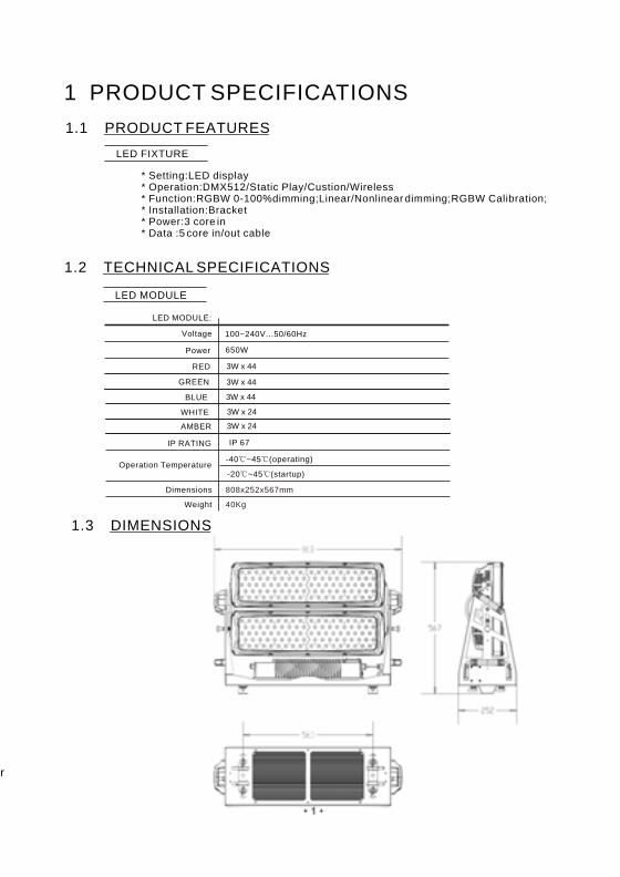
1 PRODUCT SPECIFICATIONS
1.1 PRODUCT FEATURES
LED FIXTURE
* Setting:LED display * Operation:DMX512/Static Play/Custion/Wireless* Function:RGBW 0-100%dimming;Linear/Nonlinear dimming;RGBW Calibration;* Installation:Bracket* Power:3 core in* Data :5 core in/out cable
1.2 TECHNICAL SPECIFICATIONS
LED MODULE
Dimensions
LED MODULE:
Voltage
Power
Weight
808x252x567mm
40Kg
100~240V...50/60Hz
650W
Operation Temperature-40 ~45 (operating)
-20 ~45 (startup)
IP 67
GREEN
IP RATING
WHITE 3W x 24
3W x 44RED
3W x 44
BLUE 3W x 44
1.3 DIMENSIONS
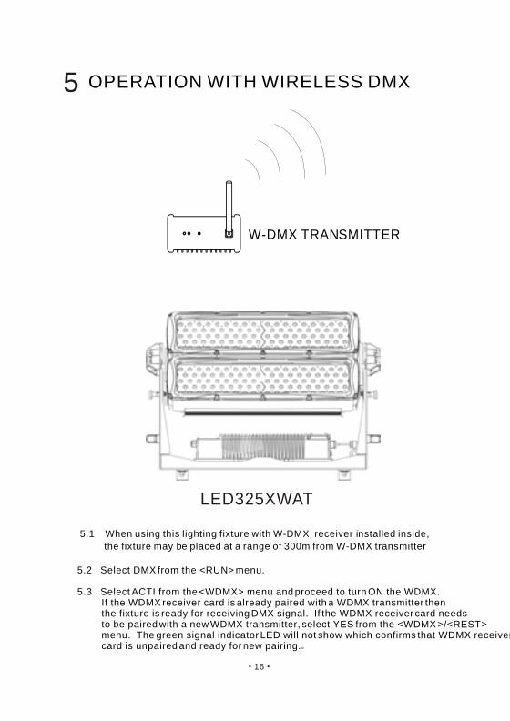
5.2 Select DMX from the <RUN> menu.
5.3 Select ACTI from the <WDMX> menu and proceed to turn ON the WDMX. If the WDMX receiver card is already paired with a WDMX transmitter then the fixture is ready for receiving DMX signal. If the WDMX receiver card needs to be paired with a new WDMX transmitter, select YES from the <WDMX >/<REST> menu. The green signal indicator LED will not show which confirms that WDMX receiver card is unpaired and ready for new pairing.
5 OPERATION WITH WIRELESS DMX
5.1 When using this lighting fixture with W-DMX receiver installed inside,
the fixture may be placed at a range of 300m from W-DMX transmitter
W-DMX TRANSMITTER
LED325XWAT
AMBER 3W x 24

152
1.4 SAFETY WARNING
IMPORTANT
ALWAYS READ THE USER MANUAL BEFORE OPERATION. PLEASE CONFIRM THAT THE POWER SUPPLY STATED ON THE PRODUCT IS THE
SAME AS THE MAINS POWER SUPPLY IN YOUR AREA.
This product must be installed by a qualified professional. Always operate the equipment as described in the user manual.A minimum distance of 0.5m must be maintained between the equipment and combustible surface.
The product must always be placed in a well ventilated area. Always make sure that the equipment is installed securely. DO NOT stand close to the equipment and stare directly into the LED light source. Always disconnect the power supply before attempting maintenance. Always make sure that the supporting structure is solid and can support the combined weight of the products.
The earth wire must always be connected to the ground. Do not touch the power cables if your hands are wet.
ATTENTION
This product left the place of manufacture in perfect condition. In order to maintain this condition and for safe operation, the user must always follow the instructions and safety warnings described in this user manual.
Avoid shaking or strong impacts to any part of the equipment. Make sure that all parts of the equipment are kept clean and free of dust. Always make sure that the power connections are connected correct and secure. If there is any malfunction of the equipment, contact your distributor immediately. When transferring the product, it is advisable to use the original packaging in which the
product left the factory. Shields, lenses or ultraviolet screens shall be changed if they have become damaged to such
an extent that their effectiveness is impaired.I t is important that the power cable is frequently inspected to ensure that there is no damagein
any position. If the power cable is damaged in any way, it should be replaced by a qualified electrical technician.
The lamp (LED) shall be changed if it has become damaged or thermally deformed.
1
2
0 255
3
0 255
0 255
HSV
1
2
0 255
3
4
0 255
0 255
0 255
5 0 255
AR3.S
7 0 255
1
2
0 255
3
4
0 255
0 255
0 255
BLOCK
5
6 0 255
7
8
0 255
0 255
0 255
CHANNEL FUNCTIONVALUE
CHANNEL FUNCTIONVALUE
CHANNEL FUNCTIONVALUE
RED
GREEN
BLUE
MASTER DIMMER
WHITE
STROBE
MODULE1 WHITE
MODULE1 BLUE
MODULE1 GREEN
MODULE1 RED
MODULE2 WHITE
MODULE2 BLUE
MODULE2 GREEN
MODULE2 RED
VALUE(0~100%)
SATURATION(0~100%)
HUE(0~100%)
6 0 255 AMBER
0 255 MODULE1 AMBER
9
10 0 255 MODULE2 AMBER

314
HANGING:
Ensure that fixture is mounted to a structure that is correct and suitable for hanging
this kind of lighting fixture
Mounting structure should withhold load of ten times fixture weight
Fixture is mounted using mounting bracket and clamps (see diagram)
A safety cable should always be used with this lighting fixture (safety cable should
withstand ten times lighting fixture weight)a
2.1-2
2.1 MOUNTING
UPRIGHT
2 INSTALLATION
The LED Fixture can be mounted in a sitting or wall mounted position using the supporting brackets.The LED Fixture should be placed on a non-flammable flat surface in any orientation and fixed by screws. There are four holes into the supporting bracket.
1
2
0 255
3
0 255
0 255
1
2
0 255
3
4
0 255
0 255
0 255
1
2
0 255
3
4
0 255
0 255
0 255
ARC.1
AR1.D
ARC.3
1
2
0 255
3
4
0 255
0 255
0 255
5 0 255
AR3.D
CHANNEL FUNCTIONVALUE
CHANNEL FUNCTIONVALUE
CHANNEL FUNCTIONVALUE
CHANNEL FUNCTIONVALUE
RED
GREEN
BLUE
RED
GREEN
BLUE
MASTER DIMMER
RED
GREEN
BLUE
WHITE
RED
GREEN
BLUE
MASTER DIMMER
WHITE
5 0 255 AMBER
6 0 255 AMBER
4 13
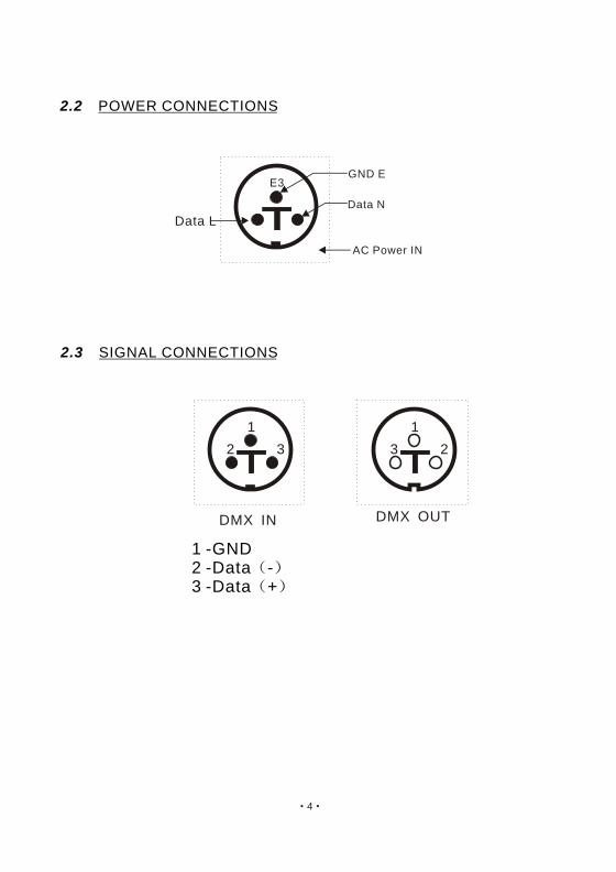
Data L
Data N
GND E
AC Power IN
E3
2 3
1
DMX IN
3 2
1
DMX OUT
1 -GND2 -Data -3 -Data +
2.2 POWER CONNECTIONS
2.3 SIGNAL CONNECTIONS
ID21
ID22
210
211
ID20200 209
ID19190 199
ID18180 189
ID14
ID15
ID16
ID17
140 149
150 159
160 169
170 179
ID65
ID66
254
255
ID8
ID9
ID10
ID11
ID12
ID13
80 89
90 99
100 109
110 119
120 129
130 139
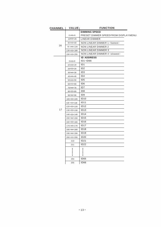
ID1~ID66
ID1
ID2
ID3
ID4
ID5
0 9
10 19
20 29
30 39
40 49
50 59
ID6
ID7
60 69
70 79
17
0 9
30 69
70 129
130 189
190 255
16
10 29
CHANNEL FUNCTIONVALUE
DIMMING SPEED
PRESET DIMMER SPEED FROM DISPLAY MENU
LINEAR DIMMER
NON LINEAR DIMMER 1 fastest
NON LINEAR DIMMER 2
NON LINEAR DIMMER 3
NON LINEAR DIMMER 4 slowest
ID ADDRESS
12 5
SET UP DOWNMENU
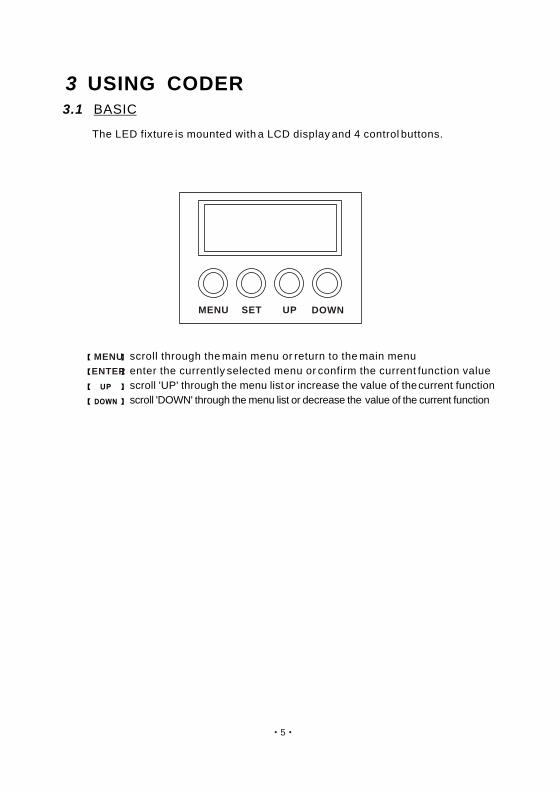
3.1 BASIC
3 USING CODER
The LED fixture is mounted with a LCD display and 4 control buttons.
enter the currently selected menu or confirm the current function value
scroll 'UP' through the menu list or increase the value of the current function
scroll 'DOWN' through the menu list or decrease the value of the current function
scroll through the main menu or return to the main menuMENU
ENTER
WHITE7 6500K
WHITE8 7200K
231 235
236 240
WHITE9 8000K
WHITE10 8500K
WHITE11 10000K
241 245
246 250
251 255
13
14
0 10
11 255
141 150
151 160
161 170
171 180
181 190
191 200
201 210
211 220
221 230
231 255
91 100
101 110
111 120
121 130
AUTO 6
AUTO 7
AUTO 8
AUTO 9
131 140 AUTO 10
0 40
41 50
51 60
61 70
71 80
81 90
AUTO 1
AUTO 2
AUTO 3
AUTO 4
AUTO 5
0 25515
12
WHITE1 3200K
WHITE2 3400K
WHITE3 4200K
WHITE4 4900K
WHITE5 5600K
WHITE6 5900K
171 200
201 205
206 210
211 215
216 220
221 225
226 230
RED100%/GREEN 100%P/BLUE100%/WHITE 100%/AMBER 100%
91 110
111 130
131 150
RED UP/GREEN 0%/BLUE100%
RED100%/GREEN 0%/BLU EDOWN
RED100%/GREEN UP/BLUE UP
151 170 RED DOWN/GREEN DOWN/BLUE 100%
CHANNEL FUNCTIONVALUE CHANNEL FUNCTIONVALUE
NO FUNCTION
STROBE
1~20Hz
AUTO
NO FUNCTION
AUTO SPEED ADJUSTMENT
When using CH14,AUTO01-AUTO10, this function activated
PR.01
PR.02
PR.03
PR.04
PR.05
PR.06
PR.07
PR.08
PR.09
PR.10
116
RUN DMX
SLAV
AT.01
AT.02
AT.10
AUTO
PR.01
PR.02
PR.10
D.(001~512)ADDR
ID I.(01~66)
TOUR
ARC.1
ARC.3
AR1.D
AR3.S
AR3.D
MENU RED
GREN
BLUE
WHIT
R.(0~255)
G.(0~255)
B.(0~255)
W.(0~255)
STRB S.(0~20)
STAT
PERS
HSV
SET UPLD
ID.ON ON
OFF
REST
RGBW
COLOR
DIM1
DIM3
DIM2
DIM4DIM
UC
OFF
OFF
BLOC
PASS
PASS
SEND END
REST END
PR.01
PR.02
PR.10
SC.01
SC.02
SC.30
RED
GREN
BLUE
WHIT
STRB
TIME
FADE
EDIT
KEY ON
OFF
WH.01
WH.02
WH.11
RED
GREN
BLUE
WHIT
R.(0~255)
G.(0~255)
B.(0~255)
W.(0~255)
CAL1
RGB.W RED
GREN
BLUE
R.(0~255)
G.(0~255)
B.(0~255)
CAL2
ACTI ON
OFF
WDMX
REST NO
YES
R.(0~255)
G.(0~255)
B.(0~255)
W.(0~255)
S.(0~20)
T.(0~255)
F.(0~255)
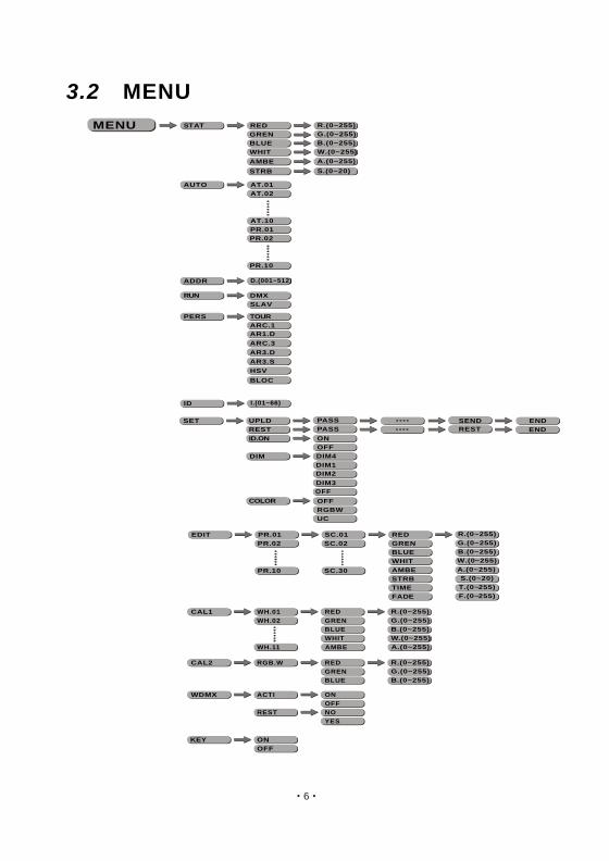
3.2 MENU
AMBE A.(0~255)
AMBE A.(0~255)
AMBE A.(0~255)
1
2
0 255
3
4
0 255
0 255
0 255
5 0 255
6
7
8
0 255
0 255
0 2559
0 255
71 90 RED 0%/GREEN DOWN/BLUE 100%
0 5
11 30
31 50
51 70
NO FUNCTION
RED100%/GREEN UP/BLUE0%
RED DOWN/GREEN 100%/BLUE0%
RED 0%/GREEN 100%/BLUE UP
10
TOUR
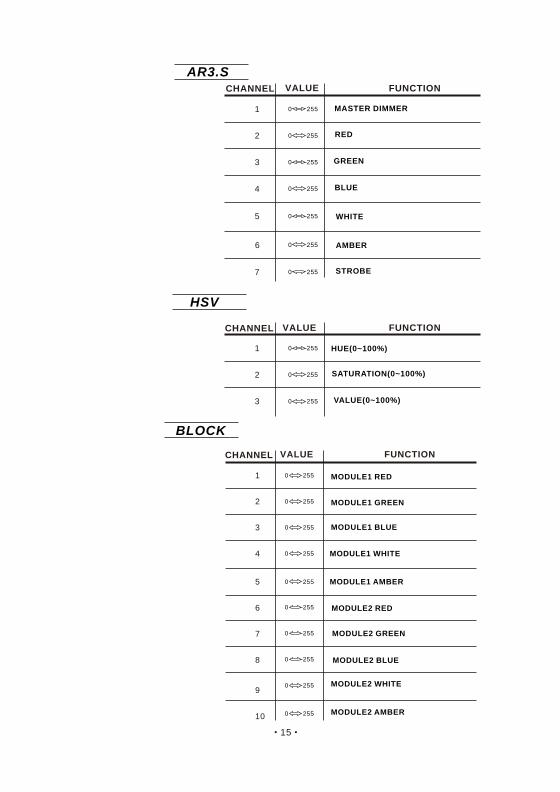
4.2 CHANNEL ASSIGNMENT
Note:This product has eight DMX512 channel configurations: TOUR. .D AR3 AR3
.ARC 1 AR1 ARC.3 .D .S HSV
and BLOC
CHANNEL FUNCTIONVALUE
MASTER DIMMER
MODULE1 WHITE
MODULE1 BLUE
MODULE1 GREEN
MODULE1 RED
MODULE2 WHITE
MODULE2 BLUE
MODULE2 GREEN
MODULE2 RED
4.1 BASIC ADDRESSING
Set the DMX512 address in the DMX menu.It is possible to have the same DMX address or independent
addresses for each fixture.
4 USING A DMX512 CONTROLLER
(or STEP TIME when CUS.01-CUS.10 in Ch14 is activated)
(or FADE TIME when CUS.01-CUS.10 in Ch14 is activated)
0 255 MODULE1 AMBER
0 25511 MODULE2 AMBER
12
710
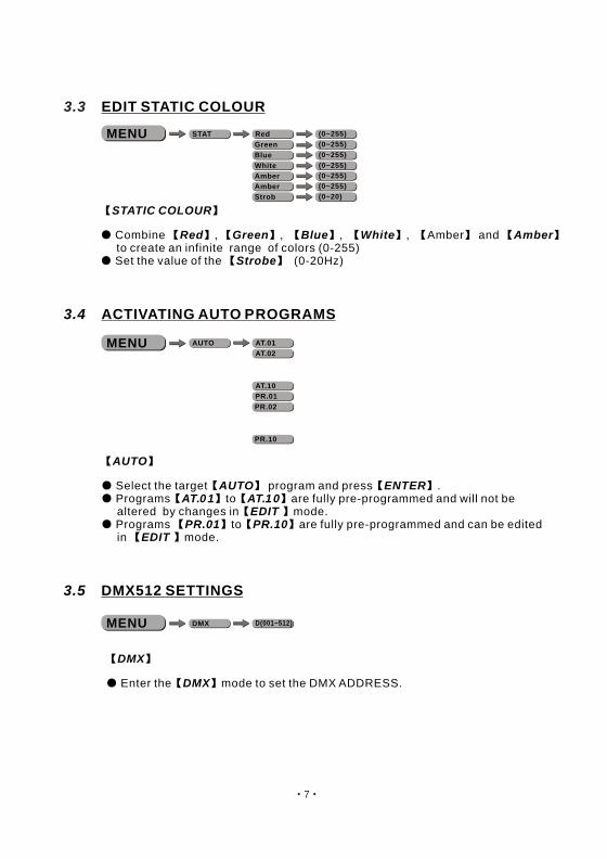
3.3 EDIT STATIC COLOUR
STATIC COLOUR
Combine Red , Green , Blue , White , Amber and Amber to create an infinite range of colors (0-255)
Set the value of the Strobe (0-20Hz)
MENU Red
Green
Blue
White
(0~255)
(0~255)
(0~255)
(0~255)
Strob (0~20)
STAT
3.4 ACTIVATING AUTO PROGRAMS
AUTO
Select the target AUTO program and press ENTER . Programs AT.01 to AT.10 are fully pre-programmed and will not be
altered by changes in EDIT mode. Programs PR.01 to PR.10 are fully pre-programmed and can be edited
in EDIT mode.
AT.01
AT.02
AT.10
AUTO
PR.01
PR.02
PR.10
MENU
3.5 DMX512 SETTINGS
DMX
Enter the DMX mode to set the DMX ADDRESS.
D(001~512)DMXMENU
Amber (0~255)
Amber (0~255)
CAL2
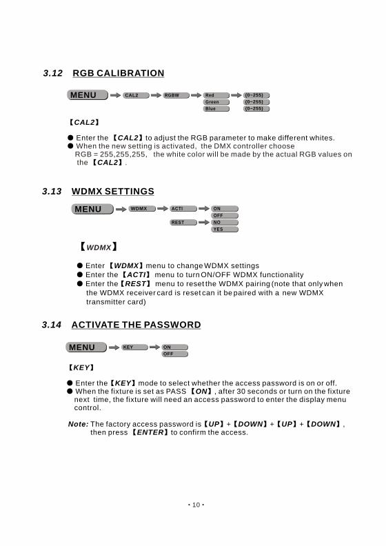
Enter the CAL2 to adjust the RGB parameter to make different whites.
CAL2
When the new setting is activated, the DMX controller choose RGB = 255,255,255, the white color will be made by the actual RGB values on the .
3.12 RGB CALIBRATION
RGBW Red
Green
Blue
(0~255)
(0~255)
(0~255)
CAL2MENU
ACTI ON
OFF
WDMX
REST NO
YES
MENU
WDMX
Enter WDMX menu to change WDMX settings Enter the ACTI menu to turn ON/OFF WDMX functionality Enter the REST menu to reset the WDMX pairing (note that only when
the WDMX receiver card is reset can it be paired with a new WDMX transmitter card)
KEY ON
OFFMENU
3.14 ACTIVATE THE PASSWORD
KEY
Enter the KEY mode to select whether the access password is on or off. When the fixture is set as PASS ON , after 30 seconds or turn on the fixture
next time, the fixture will need an access password to enter the display menu control.
Note: The factory access password is UP + DOWN + UP + DOWN , then press ENTER to confirm the access.
3.13 WDMX SETTINGS
98
3.7 PERSONALITY
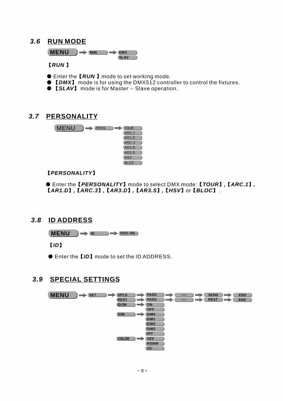
PERSONALITY
Enter the PERSONALITY mode to select DMX mode: TOUR , ARC.1 ,AR1.D , ARC.3 , AR3.D , AR3.S , HSV or BLOC .
3.8 ID ADDRESS
ID
Enter the ID mode to set the ID ADDRESS.
ID ID(01~66)MENU
RUN
Enter the RUN mode to set working mode. DMX mode is for using the DMX512 controller to control the fixtures. SLAV mode is for Master -- Slave operation.
3.6 RUN MODE
RUN DMX
SLAVMENU
TOUR
ARC.1
ARC.3
AR1.D
AR3.S
AR3.D
PERS
HSV
BLOC
MENU
3.9 SPECIAL SETTINGS
SET UPLD
ID.ON ON
OFF
REST
RGBW
COLOR
DIM1
DIM3
DIM2
DIM4DIM
UC
OFF
OFF
PASS
PASS
SEND END
REST ENDMENU
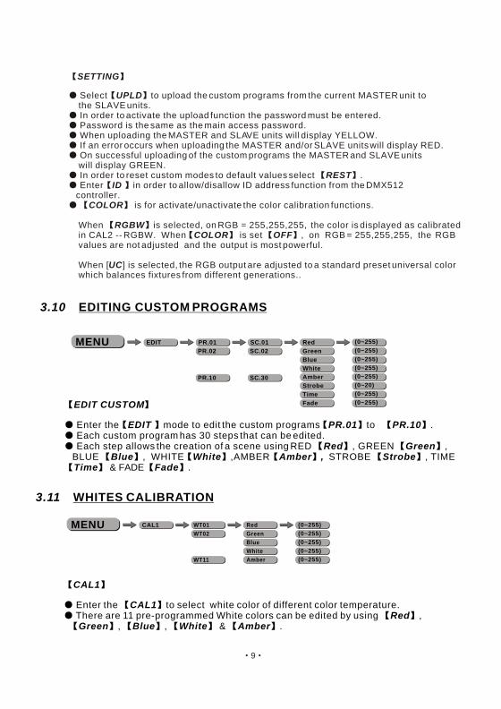
SETTING
Select UPLD to upload the custom programs from the current MASTER unit to the SLAVE units.
In order to activate the upload function the password must be entered. Password is the same as the main access password. When uploading the MASTER and SLAVE units will display YELLOW. If an error occurs when uploading the MASTER and/or SLAVE units will display RED. On successful uploading of the custom programs the MASTER and SLAVE units
will display GREEN. In order to reset custom modes to default values select REST . Enter ID in order to allow/disallow ID address function from the DMX512
controller. COLOR is for activate/unactivate the color calibration functions.
When RGBW is selected, on RGB = 255,255,255, the color is displayed as calibrated in CAL2 -- RGBW. When COLOR is set OFF , on RGB = 255,255,255, the RGB values are not adjusted and the output is most powerful. When [UC] is selected, the RGB output are adjusted to a standard preset universal color which balances fixtures from different generations..
PR.01
PR.02
PR.10
SC.01
SC.02
SC.30
Red
Green
Blue
White
Strobe
Time
Fade
(0~255)
(0~255)
(0~255)
(0~255)
(0~20)
(0~255)
(0~255)
EDITMENU
3.10 EDITING CUSTOM PROGRAMS
EDIT CUSTOM
Enter the EDIT mode to edit the custom programs PR.01 to PR.10 . Each custom program has 30 steps that can be edited. Each step allows the creation of a scene using RED Red , GREEN Green ,
BLUE Blue , WHITE White ,AMBER Amber , STROBE Strobe , TIMETime & FADE Fade .
WT01
WT02
WT11
Red
Green
Blue
White
(0~255)
(0~255)
(0~255)
(0~255)
CAL1MENU
CAL1
Enter the CAL1 to select white color of different color temperature. There are 11 pre-programmed White colors can be edited by using Red ,
Green , Blue , White & Amber .
3.11 WHITES CALIBRATION
Amber (0~255)
Amber (0~255)
98
3.7 PERSONALITY
PERSONALITY
Enter the PERSONALITY mode to select DMX mode: TOUR , ARC.1 ,AR1.D , ARC.3 , AR3.D , AR3.S , HSV or BLOC .
3.8 ID ADDRESS
ID
Enter the ID mode to set the ID ADDRESS.
ID ID(01~66)MENU
RUN
Enter the RUN mode to set working mode. DMX mode is for using the DMX512 controller to control the fixtures. SLAV mode is for Master -- Slave operation.
3.6 RUN MODE
RUN DMX
SLAVMENU
TOUR
ARC.1
ARC.3
AR1.D
AR3.S
AR3.D
PERS
HSV
BLOC
MENU
3.9 SPECIAL SETTINGS
SET UPLD
ID.ON ON
OFF
REST
RGBW
COLOR
DIM1
DIM3
DIM2
DIM4DIM
UC
OFF
OFF
PASS
PASS
SEND END
REST ENDMENU
SETTING
Select UPLD to upload the custom programs from the current MASTER unit to the SLAVE units.
In order to activate the upload function the password must be entered. Password is the same as the main access password. When uploading the MASTER and SLAVE units will display YELLOW. If an error occurs when uploading the MASTER and/or SLAVE units will display RED. On successful uploading of the custom programs the MASTER and SLAVE units
will display GREEN. In order to reset custom modes to default values select REST . Enter ID in order to allow/disallow ID address function from the DMX512
controller. COLOR is for activate/unactivate the color calibration functions.
When RGBW is selected, on RGB = 255,255,255, the color is displayed as calibrated in CAL2 -- RGBW. When COLOR is set OFF , on RGB = 255,255,255, the RGB values are not adjusted and the output is most powerful. When [UC] is selected, the RGB output are adjusted to a standard preset universal color which balances fixtures from different generations..
PR.01
PR.02
PR.10
SC.01
SC.02
SC.30
Red
Green
Blue
White
Strobe
Time
Fade
(0~255)
(0~255)
(0~255)
(0~255)
(0~20)
(0~255)
(0~255)
EDITMENU
3.10 EDITING CUSTOM PROGRAMS
EDIT CUSTOM
Enter the EDIT mode to edit the custom programs PR.01 to PR.10 . Each custom program has 30 steps that can be edited. Each step allows the creation of a scene using RED Red , GREEN Green ,
BLUE Blue , WHITE White ,AMBER Amber , STROBE Strobe , TIMETime & FADE Fade .
WT01
WT02
WT11
Red
Green
Blue
White
(0~255)
(0~255)
(0~255)
(0~255)
CAL1MENU
CAL1
Enter the CAL1 to select white color of different color temperature. There are 11 pre-programmed White colors can be edited by using Red ,
Green , Blue , White & Amber .
3.11 WHITES CALIBRATION
Amber (0~255)
Amber (0~255)
710
3.3 EDIT STATIC COLOUR
STATIC COLOUR
Combine Red , Green , Blue , White , Amber and Amber to create an infinite range of colors (0-255)
Set the value of the Strobe (0-20Hz)
MENU Red
Green
Blue
White
(0~255)
(0~255)
(0~255)
(0~255)
Strob (0~20)
STAT
3.4 ACTIVATING AUTO PROGRAMS
AUTO
Select the target AUTO program and press ENTER . Programs AT.01 to AT.10 are fully pre-programmed and will not be
altered by changes in EDIT mode. Programs PR.01 to PR.10 are fully pre-programmed and can be edited
in EDIT mode.
AT.01
AT.02
AT.10
AUTO
PR.01
PR.02
PR.10
MENU
3.5 DMX512 SETTINGS
DMX
Enter the DMX mode to set the DMX ADDRESS.
D(001~512)DMXMENU
Amber (0~255)
Amber (0~255)
CAL2
Enter the CAL2 to adjust the RGB parameter to make different whites.
CAL2
When the new setting is activated, the DMX controller choose RGB = 255,255,255, the white color will be made by the actual RGB values on the .
3.12 RGB CALIBRATION
RGBW Red
Green
Blue
(0~255)
(0~255)
(0~255)
CAL2MENU
ACTI ON
OFF
WDMX
REST NO
YES
MENU
WDMX
Enter WDMX menu to change WDMX settings Enter the ACTI menu to turn ON/OFF WDMX functionality Enter the REST menu to reset the WDMX pairing (note that only when
the WDMX receiver card is reset can it be paired with a new WDMX transmitter card)
KEY ON
OFFMENU
3.14 ACTIVATE THE PASSWORD
KEY
Enter the KEY mode to select whether the access password is on or off. When the fixture is set as PASS ON , after 30 seconds or turn on the fixture
next time, the fixture will need an access password to enter the display menu control.
Note: The factory access password is UP + DOWN + UP + DOWN , then press ENTER to confirm the access.
3.13 WDMX SETTINGS

116
RUN DMX
SLAV
AT.01
AT.02
AT.10
AUTO
PR.01
PR.02
PR.10
D.(001~512)ADDR
ID I.(01~66)
TOUR
ARC.1
ARC.3
AR1.D
AR3.S
AR3.D
MENU RED
GREN
BLUE
WHIT
R.(0~255)
G.(0~255)
B.(0~255)
W.(0~255)
STRB S.(0~20)
STAT
PERS
HSV
SET UPLD
ID.ON ON
OFF
REST
RGBW
COLOR
DIM1
DIM3
DIM2
DIM4DIM
UC
OFF
OFF
BLOC
PASS
PASS
SEND END
REST END
PR.01
PR.02
PR.10
SC.01
SC.02
SC.30
RED
GREN
BLUE
WHIT
STRB
TIME
FADE
EDIT
KEY ON
OFF
WH.01
WH.02
WH.11
RED
GREN
BLUE
WHIT
R.(0~255)
G.(0~255)
B.(0~255)
W.(0~255)
CAL1
RGB.W RED
GREN
BLUE
R.(0~255)
G.(0~255)
B.(0~255)
CAL2
ACTI ON
OFF
WDMX
REST NO
YES
R.(0~255)
G.(0~255)
B.(0~255)
W.(0~255)
S.(0~20)
T.(0~255)
F.(0~255)
3.2 MENU
AMBE A.(0~255)
AMBE A.(0~255)
AMBE A.(0~255)
1
2
0 255
3
4
0 255
0 255
0 255
5 0 255
6
7
8
0 255
0 255
0 2559
0 255
71 90 RED 0%/GREEN DOWN/BLUE 100%
0 5
11 30
31 50
51 70
NO FUNCTION
RED100%/GREEN UP/BLUE0%
RED DOWN/GREEN 100%/BLUE0%
RED 0%/GREEN 100%/BLUE UP
10
TOUR
4.2 CHANNEL ASSIGNMENT
Note:This product has eight DMX512 channel configurations: TOUR. .D AR3 AR3
.ARC 1 AR1 ARC.3 .D .S HSV
and BLOC
CHANNEL FUNCTIONVALUE
MASTER DIMMER
MODULE1 WHITE
MODULE1 BLUE
MODULE1 GREEN
MODULE1 RED
MODULE2 WHITE
MODULE2 BLUE
MODULE2 GREEN
MODULE2 RED
4.1 BASIC ADDRESSING
Set the DMX512 address in the DMX menu.It is possible to have the same DMX address or independent
addresses for each fixture.
4 USING A DMX512 CONTROLLER
(or STEP TIME when CUS.01-CUS.10 in Ch14 is activated)
(or FADE TIME when CUS.01-CUS.10 in Ch14 is activated)
0 255 MODULE1 AMBER
0 25511 MODULE2 AMBER
12

12 5
SET UP DOWNMENU
3.1 BASIC
3 USING CODER
The LED fixture is mounted with a LCD display and 4 control buttons.
enter the currently selected menu or confirm the current function value
scroll 'UP' through the menu list or increase the value of the current function
scroll 'DOWN' through the menu list or decrease the value of the current function
scroll through the main menu or return to the main menuMENU
ENTER
WHITE7 6500K
WHITE8 7200K
231 235
236 240
WHITE9 8000K
WHITE10 8500K
WHITE11 10000K
241 245
246 250
251 255
13
14
0 10
11 255
141 150
151 160
161 170
171 180
181 190
191 200
201 210
211 220
221 230
231 255
91 100
101 110
111 120
121 130
AUTO 6
AUTO 7
AUTO 8
AUTO 9
131 140 AUTO 10
0 40
41 50
51 60
61 70
71 80
81 90
AUTO 1
AUTO 2
AUTO 3
AUTO 4
AUTO 5
0 25515
12
WHITE1 3200K
WHITE2 3400K
WHITE3 4200K
WHITE4 4900K
WHITE5 5600K
WHITE6 5900K
171 200
201 205
206 210
211 215
216 220
221 225
226 230
RED100%/GREEN 100%P/BLUE100%/WHITE 100%/AMBER 100%
91 110
111 130
131 150
RED UP/GREEN 0%/BLUE100%
RED100%/GREEN 0%/BLU EDOWN
RED100%/GREEN UP/BLUE UP
151 170 RED DOWN/GREEN DOWN/BLUE 100%
CHANNEL FUNCTIONVALUE CHANNEL FUNCTIONVALUE
NO FUNCTION
STROBE
1~20Hz
AUTO
NO FUNCTION
AUTO SPEED ADJUSTMENT
When using CH14,AUTO01-AUTO10, this function activated
PR.01
PR.02
PR.03
PR.04
PR.05
PR.06
PR.07
PR.08
PR.09
PR.10
4 13
Data L
Data N
GND E
AC Power IN
E3
2 3
1
DMX IN
3 2
1
DMX OUT
1 -GND2 -Data -3 -Data +
2.2 POWER CONNECTIONS
2.3 SIGNAL CONNECTIONS
ID21
ID22
210
211
ID20200 209
ID19190 199
ID18180 189
ID14
ID15
ID16
ID17
140 149
150 159
160 169
170 179
ID65
ID66
254
255
ID8
ID9
ID10
ID11
ID12
ID13
80 89
90 99
100 109
110 119
120 129
130 139
ID1~ID66
ID1
ID2
ID3
ID4
ID5
0 9
10 19
20 29
30 39
40 49
50 59
ID6
ID7
60 69
70 79
17
0 9
30 69
70 129
130 189
190 255
16
10 29
CHANNEL FUNCTIONVALUE
DIMMING SPEED
PRESET DIMMER SPEED FROM DISPLAY MENU
LINEAR DIMMER
NON LINEAR DIMMER 1 fastest
NON LINEAR DIMMER 2
NON LINEAR DIMMER 3
NON LINEAR DIMMER 4 slowest
ID ADDRESS

314
HANGING:
Ensure that fixture is mounted to a structure that is correct and suitable for hanging
this kind of lighting fixture
Mounting structure should withhold load of ten times fixture weight
Fixture is mounted using mounting bracket and clamps (see diagram)
A safety cable should always be used with this lighting fixture (safety cable should
withstand ten times lighting fixture weight)a
2.1-2
2.1 MOUNTING
UPRIGHT
2 INSTALLATION
The LED Fixture can be mounted in a sitting or wall mounted position using the supporting brackets.The LED Fixture should be placed on a non-flammable flat surface in any orientation and fixed by screws. There are four holes into the supporting bracket.
1
2
0 255
3
0 255
0 255
1
2
0 255
3
4
0 255
0 255
0 255
1
2
0 255
3
4
0 255
0 255
0 255
ARC.1
AR1.D
ARC.3
1
2
0 255
3
4
0 255
0 255
0 255
5 0 255
AR3.D
CHANNEL FUNCTIONVALUE
CHANNEL FUNCTIONVALUE
CHANNEL FUNCTIONVALUE
CHANNEL FUNCTIONVALUE
RED
GREEN
BLUE
RED
GREEN
BLUE
MASTER DIMMER
RED
GREEN
BLUE
WHITE
RED
GREEN
BLUE
MASTER DIMMER
WHITE
5 0 255 AMBER
6 0 255 AMBER
152
1.4 SAFETY WARNING
IMPORTANT
ALWAYS READ THE USER MANUAL BEFORE OPERATION. PLEASE CONFIRM THAT THE POWER SUPPLY STATED ON THE PRODUCT IS THE
SAME AS THE MAINS POWER SUPPLY IN YOUR AREA.
This product must be installed by a qualified professional. Always operate the equipment as described in the user manual.A minimum distance of 0.5m must be maintained between the equipment and combustible surface.
The product must always be placed in a well ventilated area. Always make sure that the equipment is installed securely. DO NOT stand close to the equipment and stare directly into the LED light source. Always disconnect the power supply before attempting maintenance. Always make sure that the supporting structure is solid and can support the combined weight of the products.
The earth wire must always be connected to the ground. Do not touch the power cables if your hands are wet.
ATTENTION
This product left the place of manufacture in perfect condition. In order to maintain this condition and for safe operation, the user must always follow the instructions and safety warnings described in this user manual.
Avoid shaking or strong impacts to any part of the equipment. Make sure that all parts of the equipment are kept clean and free of dust. Always make sure that the power connections are connected correct and secure. If there is any malfunction of the equipment, contact your distributor immediately. When transferring the product, it is advisable to use the original packaging in which the
product left the factory. Shields, lenses or ultraviolet screens shall be changed if they have become damaged to such
an extent that their effectiveness is impaired.I t is important that the power cable is frequently inspected to ensure that there is no damagein
any position. If the power cable is damaged in any way, it should be replaced by a qualified electrical technician.
The lamp (LED) shall be changed if it has become damaged or thermally deformed.
1
2
0 255
3
0 255
0 255
HSV
1
2
0 255
3
4
0 255
0 255
0 255
5 0 255
AR3.S
7 0 255
1
2
0 255
3
4
0 255
0 255
0 255
BLOCK
5
6 0 255
7
8
0 255
0 255
0 255
CHANNEL FUNCTIONVALUE
CHANNEL FUNCTIONVALUE
CHANNEL FUNCTIONVALUE
RED
GREEN
BLUE
MASTER DIMMER
WHITE
STROBE
MODULE1 WHITE
MODULE1 BLUE
MODULE1 GREEN
MODULE1 RED
MODULE2 WHITE
MODULE2 BLUE
MODULE2 GREEN
MODULE2 RED
VALUE(0~100%)
SATURATION(0~100%)
HUE(0~100%)
6 0 255 AMBER
0 255 MODULE1 AMBER
9
10 0 255 MODULE2 AMBER
116
1 PRODUCT SPECIFICATIONS
1.1 PRODUCT FEATURES
LED FIXTURE
* Setting:LED display * Operation:DMX512/Static Play/Custion/Wireless* Function:RGBW 0-100%dimming;Linear/Nonlinear dimming;RGBW Calibration;* Installation:Bracket* Power:3 core in* Data :5 core in/out cable
1.2 TECHNICAL SPECIFICATIONS
LED MODULE
Dimensions
LED MODULE:
Voltage
Power
Weight
808x252x567mm
40Kg
100~240V...50/60Hz
650W
Operation Temperature-40 ~45 (operating)
-20 ~45 (startup)
IP 67
GREEN
IP RATING
WHITE 3W x 24
3W x 44RED
3W x 44
BLUE 3W x 44
1.3 DIMENSIONS
5.2 Select DMX from the <RUN> menu.
5.3 Select ACTI from the <WDMX> menu and proceed to turn ON the WDMX. If the WDMX receiver card is already paired with a WDMX transmitter then the fixture is ready for receiving DMX signal. If the WDMX receiver card needs to be paired with a new WDMX transmitter, select YES from the <WDMX >/<REST> menu. The green signal indicator LED will not show which confirms that WDMX receiver card is unpaired and ready for new pairing.
5 OPERATION WITH WIRELESS DMX
5.1 When using this lighting fixture with W-DMX receiver installed inside,
the fixture may be placed at a range of 300m from W-DMX transmitter
W-DMX TRANSMITTER
LED325XWAT
AMBER 3W x 24

17
ABLE OF CONTENTSTPART 1 PRODUCT SPECIFICATIONS...........................................1.
1.1--PRODUCT FEATURES.................................................................1.
1.2--TECHNICAL SPECIFICATIONS.....................................................1.
1.3--DIMENSIONS...............................................................................1.
PART 2 INSTALLATION...............................................................3.2.1--MOUNTING..................................................................................3.
2.3--SIGNAL CONNECTIONS...............................................................4.
2.2--POWER CONNECTIONS...............................................................4.
PART 4 USING DMX512 CONTROLLER......................................11. 4.1--BASIC ADDRESSING ................................................................ 11.
PART 3 USING CODER.................................................................5.
PART 5 OPERATION WITH WIRELESS DMX................................16.
3.1--BASIC..........................................................................................5.
3.3--EDIT STATIC COLOUR..................................................................7.
3.2--MENU..........................................................................................6.
3.4--ACTIVATING AUTO PROGRAMS...................................................7.
3.7--PERSONALITY............................................................................8.
1.4--SAFETY WARNING......................................................................2.
3.9--SPECIAL SETTINGS....................................................................8.
3.10--EDITING CUSTOM PROGRAMS.................................................9.
3.8--ID ADDRESS...............................................................................8.
PART 6 APPENDIX......................................................................18. 6.1--MAINTENANCE.........................................................................18.
5.4 By pressing the RESET button on W-DMX transmitter, transmitter will search for RESET
lighting fixtures. During search transmitter green SIGNAL indicator will flash. After
pairing with lighting fixture green SIGNAL indicator will display.
POWER SIGNALANTENNA
RESET
5.5 Once a lighting fixture has been paired with a W-DMX transmitter, the green SIGNAL indicator
will display. Once a lighting fixture has been paired with a W-DMX transmitter, the lighting
fixture cannot be paired with another W-DMX transmitter. If a lighting fixture requires pairing
with a new W-DMX transmitter, steps 5.3 and 5.4 must be repeated.
SET UP DOWNMENU
WDMX green signal indicator LED
4.2--CHANNEL ASSIGNMENT........................................................... 11.
3.5--DMX512 SETTINGS......................................................................7.
3.6--RUN MODE..................................................................................8.
3.11--WHITES CALIBRATION..............................................................9.
3.13--WDMX SETTINGS...................................................................10.
3.10--ACTIVATE THE PASSWORD.....................................................10.
3.12--RGB CALIBRATION.................................................................10.
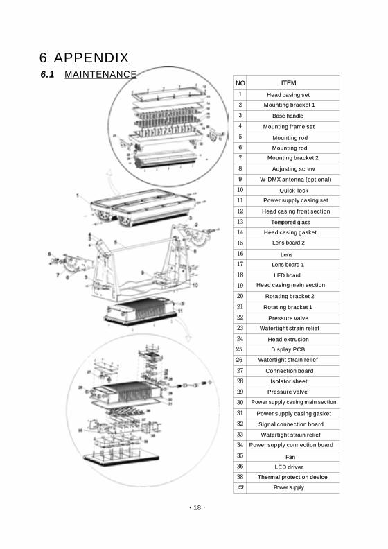
6 APPENDIX6.1 MAINTENANCE
Isolator sheetIsolator sheet
Thermal protection deviceThermal protection device
Head casing front sectionHead casing front section
Head casing gasketHead casing gasket
Head casing main sectionHead casing main section
Rotating bracket 2Rotating bracket 2
Pressure valvePressure valve
Watertight strain reliefWatertight strain relief
Power supply casing setPower supply casing set
W-DMX antenna (optional)W-DMX antenna (optional)
Quick-lockQuick-lock
Mounting bracket 1Mounting bracket 1
Mounting rodMounting rod
Adjusting screwAdjusting screw
Mounting bracket 2Mounting bracket 2
Mounting frame setMounting frame set
Head casing set Head casing set
LED driverLED driver
Power supply connection boardPower supply connection board
Signal connection boardSignal connection board
Connection board Connection board
Power supply casing gasketPower supply casing gasket
Power supply casing main sectionPower supply casing main section
Pressure valvePressure valve
Watertight strain reliefWatertight strain relief
Watertight strain reliefWatertight strain relief
NONO ITEMITEM
Base handleBase handle
Tempered glassTempered glass
Lens board 1Lens board 1
Lens Lens
Lens board 2Lens board 2
LED boardLED board
FanFan
Power supply Power supply
Mounting rodMounting rod
Rotating bracket 1Rotating bracket 1
Head extrusionHead extrusion
Display PCBDisplay PCB
18


![Untitled-5 [] · kg/cm2 Transmitt xomcs . Title: Untitled-5 Author: Created Date: 12/5/2008 5:11:22 PM](https://img.pdfslide.us/doc/110x75/5ffe770fbf765b2188424816/untitled-5-kgcm2-transmitt-xomcs-title-untitled-5-author-created-date.jpg)