Embed Size (px)
Citation preview
ELSEVIER Mechanics of Materials 23 (1996) 255-270
MECHANICS OF
MATERIALS
Explosively generated pulse propagation through particles containing natural cracks
Raman Singh a, Arun Shukla a , * , Harry Zervas b a Dynamic Photomechanics Laboratory, Department of Mechanical Engineering and Applied Mechanics, University of Rhode Island,
Kingston, RI 02881, USA b Naval Undersea Warfare Center, Mechanical Systems Division, Newport, RI 02841, USA
Received 10 July 1995; revised version received 13 May 1996
Abstract
An experimental study is conducted to study dynamic load transfer through particulate assemblies containing a damaged particle. The assembly is simulated by a one-dimensional array of circular disks, and the damage itself by a natural, zero-width crack. This assembly is explosively loaded and the dynamic load transfer process observed using dynamic photoelasticity and strain gages, as the stress wave pulse propagates down the assembly. Attention is focussed on the influence of damage size and orientation on the group wave velocity, wave dispersion and peak contact load attenuation of the stress wave pulse. Damage growth occurring from the interaction of the stress wave pulse with the closed natural crack tip is also studied. The results demonstrate that the inclusion of a damaged particle greatly influences the load transfer process, both locally and in the far field. The degree to which the damaged particle modifies the load transfer process is more dependent upon the orientation of the natural crack than upon the size of the crack. Moreover, damage growth within the damaged particles is also a strong function of the orientation of the natural crack.
Keywords: Damage; Granular media; Load transfer; Particulate assembly; Stress wave propagation
1. Introduct ion
This paper presents the results from an experi- mental investigation conducted to study dynamic load transfer through particulate assemblies contain- ing a damaged particle. The assembly was simulated by a one-dimensional array of circular disks, and the damage by a natural crack. This assembly was explo- sively loaded and the resulting dynamic load transfer was observed using dynamic photoelasticity and
* Corresponding author. Tel.: + 1-401-8742283; fax: + 1-401- 8742355; e-mail: [email protected].
strain gages. The two techniques were employed in separate experiments to obtain the stress and strain fields at various contact locations, as the explosively generated stress wave propagated through the partic- ulate assembly. The evaluation of these transient stress and strain fields elucidated the various mecha- nisms that govern dynamic load transfer through damaged particulate assemblies and hence through damaged granular media.
The motivation for this study arises from the need to understand dynamic load transfer through granular media. This information is important to several areas of technology such as soil mechanics, seismology, compact ion of powders, etc. The response of a gran-
0167-6636/96/$15.00 Copyright © 1996 Elsevier Science B.V. All rights reserved. PII S01 6 7 - 6 6 3 6 ( 9 6 ) 0 0 0 2 6 - 9
256 R. Singh et al. / Mechanics of Materials 23 (1996) 255-270
ular medium to rapid loading represents a fairly complex problem and has been of interest to many researchers. Typically, researchers have employed both numerical and experimental techniques to inves- tigate dynamic load transfer through granular media simulated by particulate assemblies (Subhash et al., 1991; Rotherburg and Bathurst, 1992; Shukla et al., 1993a). Recently, Shukla et al. (1993b) have em- ployed dynamic photoelasticity to evaluate the dy- namic response of undamaged particulate media us- ing assemblies of circular and elliptical particles subjected to explosive loading. Researchers (Walton, 1987; Trent, 1989; Ting and Corkum, 1992; Sadd et al., 1993) have also used a variety of numerical techniques to predict the dynamic response of granu- lar media. Most recently, Singh et al. (1996) have conducted an experimental investigation to study dynamic load transfer through particulate assemblies containing notched particles. They demonstrated that the size and orientation of the notch greatly influ- ences the load transfer process. The current study focusses on the effect of closed sharp cracks on dynamic load transfer in particulate assemblies sub- jected to explosive loading. The effects of crack size and orientation on the load transfer process are ex- amined in detail. Finally, a comparison is drawn with the case of open notched flaws.
2. Experimental procedure and analysis
A series of experiments was conducted on a one-dimensional assembly (or, single chain) of circu- lar disks which were dynamically loaded by detonat- ing an explosive on one end of the assembly. The assembly included a damaged particle containing a closed natural crack as the flaw. Both the size and orientation of the crack were systematically varied and the dynamic load transfer process was observed using two different experimental techniques. These techniques are namely, dynamic photoelasticity in conjunction with high-speed photography and elec- trical resistance strain gages. These two techniques were selected because of the complementary nature of information supplied by them, which when cou- pled together provides a complete assessment of the dynamic event. Dynamic photoelasticity is a full field experimental technique and provides complete
qualitative and quantitative information about the load transfer process. However, limitations in the field of view of the high speed camera (0.032 m 2) restricts the number of disks that can be observed and analyzed in a given experiment. Thus, electrical resistance strain gages are employed to provide point-wise information over the entire particulate assembly.
The circular disks used to simulate granular media were machined from Homalite-100, a brittle, trans- parent polyester. This material exhibits stress in- duced birefringence and is ideally suited for photoe- lastic studies. The flaw in the damaged disks was fabricated by initially machining a small starter notch. The disk was held in a vise and subjected to some compressive loading in the transverse direction. Then a sharp knife was tapped at the tip of the starter notch to initiate and propagate a closed natural crack. Controlling the pressure on the knife determined the length of the crack induced in the disk.
2.1. Photoelastic approach: local observations
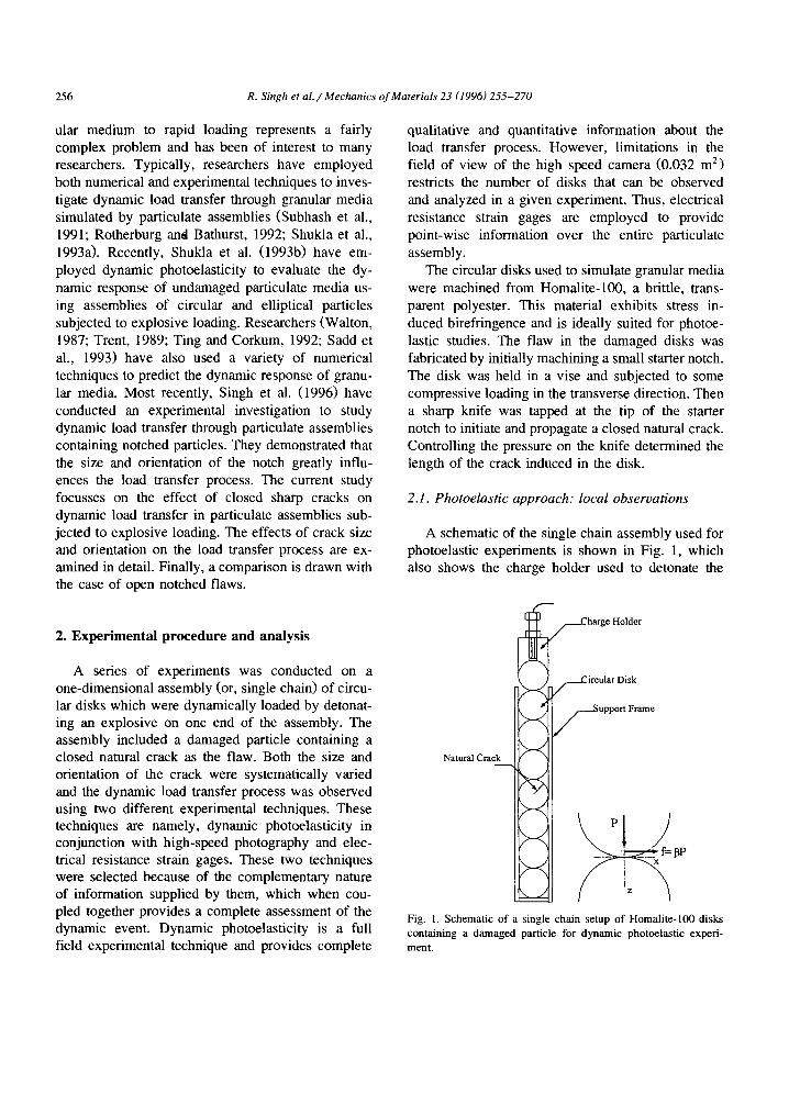
A schematic of the single chain assembly used for photoelastic experiments is shown in Fig. 1, which also shows the charge holder used to detonate the
N~u~ C~ck
harge Holder
ircular Disk
upport Frame
Fig. 1. Schematic of a single chain setup of Homalite-100 disks containing a damaged particle for dynamic photoelastic experi- ment.
R. Singh et al. / Mechanics of Materials 23 (1996) 255-270 257
explosive. The assembly was placed in the optical bench of a multiple spark-gap Cranz-Schardin high-speed camera. This high speed camera records 20 photographic images of the dynamic event at a predetermined framing rate of up to a million frames/second. The explosive was detonated which caused a stress wave to propagate down the assem- bly of disks. The camera was synchronized to record photographs of the dynamic event after a predeter- mined time following the explosion.
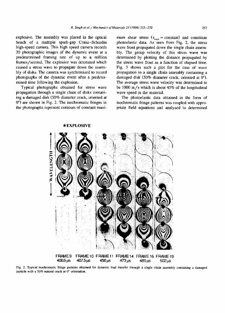
Typical photographs obtained for stress wave propagation through a single chain of disks contain- ing a damaged disk (50% diameter crack, oriented at 0 °) are shown in Fig. 2. The isochromatic fringes in the photographs represent contours of constant maxi-
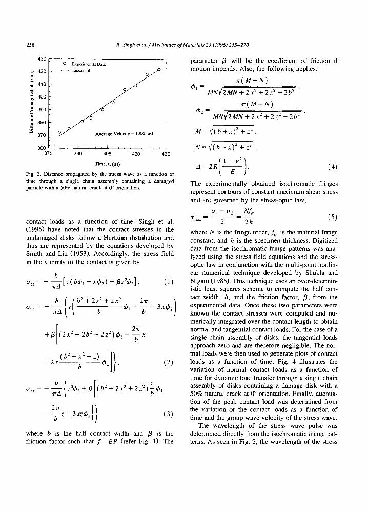
mum shear stress (~'max = constant) and constitute photoelastic data. As seen from Fig. 2, the stress wave front propagated down the single chain assem- bly. The group velocity of this stress wave was determined by plotting the distance propagated by the stress wave front as a function of elapsed time. Fig. 3 shows such a plot for the case of wave propagation in a single chain assembly containing a damaged disk (50% diameter crack, oriented at 0°). The average stress wave velocity was determined to be 1000 m / s which is about 45% of the longitudinal wave speed in the material.
The photoelastic data obtained in the form of isochromatic fringe patterns was coupled with appro- priate field equations and analyzed to determined
T 0 Z
l
"kEXPLOSIVE
! •
!
i
FRAME9 FRAMEIO FRAME11 FRAME14 FRAME16 FRAME19 4005ps 407.5ps 4 5 6 p s 4 7 3 p s 4 8 5 ~ s 5021~s
Fig. 2. Typical isochromatic fringe patterns obtained for dynamic load transfer through a single chain assembly containing a damaged particle with a 50% natural crack at 0 ° orientation.
258 R. Singh et al. / Mechanics of Materials 23 (1996) 255-270
430
420 E E
410
400
~ 3 9 0
380
370
360 37, ~
0 Experimental Data
O/,." Average Velocity = 1000 m/s
i t i I [ B i ~ ~ [ i r i i I i i i i
390 405 420 435
Time, t, (Its)
Fig. 3. Distance propagated by the stress wave as a function of time through a single chain assembly containing a damaged particle with a 50% natural crack at 0 ° orientation.
contact loads as a function of time. Singh et al. (1996) have noted that the contact stresses in the undamaged disks follow a Hertzian distribution and thus are represented by the equations developed by Smith and Liu (1953). Accordingly, the stress field in the vicinity of the contact is given by
b 0-zz rrA [ z( bqbl - xqb2) +/3z2~b2]' (1)
-xx b { ( b 2 + 2 z 2 + 2 x 2 2rr 3x4,2)
"n'A Z b (hi - -'~- -
+/3 2~-
( 2 x 2 - 2b 2 - 2 Z2) (h2 + --~- x
+ 2 x 2x2z, ]}
b 4'2 , (2 )
~ z ( [ z b z24~2+~ (b2+2x2+2z2)g 4''
7rA
b z - 3xzch2 (3)
where b is the half contact width and /3 is the friction factor such that f = t iP (refer Fig. 1). The
parameter /3 will be the coefficient of friction if motion impends. Also, the following applies:
7r( M + N)
ch~ = MN~/2MN + 2x 2 + 2 z 2 - 2b 2 ,
rr( M - N )
492 = MN1/2MN + 2 x 2 + 2z 2 - 2b 2 '
M = ¢( b + x)2 + z 2 ,
N = ~( b - x)2 + z 2 ,
The experimentally obtained isochromatic fringes represent contours of constant maximum shear stress and are governed by the stress-optic law,
0-1 -- 0"2 Nf~ T m a x - ~ - - 2"'h ( 5 )
where N is the fringe order, f,~ is the material fringe constant, and h is the specimen thickness. Digitized data from the isochromatic fringe patterns was ana- lyzed using the stress field equations and the stress- optic law in conjunction with the multi-point nonlin- ear numerical technique developed by Shukla and Nigam (1985). This technique uses an over-determin- istic least squares scheme to compute the half con- tact width, b, and the friction factor, /3, from the experimental data. Once these two parameters were known the contact stresses were computed and nu- merically integrated over the contact length to obtain normal and tangential contact loads. For the case of a single chain assembly of disks, the tangential loads approach zero and are therefore negligible. The nor- mal loads were then used to generate plots of contact loads as a function of time. Fig. 4 illustrates the variation of normal contact loads as a function of time for dynamic load transfer through a single chain assembly of disks containing a damage disk with a 50% natural crack at 0 ° orientation. Finally, attenua- tion of the peak contact load was determined from the variation of the contact loads as a function of time and the group wave velocity of the stress wave.
The wavelength of the stress wave pulse was determined directly from the isochromatic fringe pat- terns. As seen in Fig. 2, the wavelength of the stress
R. Singh et al. / Mechanics of Materials 23 (1996) 255-270 259
1 .2
t
= ¢J
0.8 ( ~ 13-14
0.6 ( ~ 14-15
0.4 v 12-13 d O 13-14 /
0.2 & 1 4 - 1 5 :
0.0 . . . . ~ . . . . , , , , I , , , , r I I I
300 350 400 450 500 550
Time, t, (.us)
Fig. 4. Variation of normal contact loads for dynamic load transfer through a single chain assembly containing a damaged particle with a 50% natural crack at 0 ° orientation.
wave pulse was observed to be approximately four disk diameters. Shukla et al. (1993b) have shown that such a wavelength is characteristic for stress wave propagation in single chain assemblies of un- damaged circular disks.
2.2. Strain gage approach: Far-field observations
Strain gages (MicroMeasurements: EA-13- 031DE-120) were employed to provide point-wise information near the contact points over the entire paniculate assembly. This complements photoelastic experiments by providing global (or far-field) infor- mation about the dynamic load transfer process. As shown in Fig. 5, a total of eight strain gages were employed to monitor the dynamic strain field at
Explosive Holder Damaged Disk
I S~ainGages
Ec~on LeCroy Dynamic Aquisifion Amplifier System
Fig. 5. Schematic of a single chain setup of Homalite-100 disks containing a damaged panicle for strain gage experiment.
==
r~
0 0
- 3 0 0 0 -
-6OOO -9000
-12000
- 3 0 0 0 -
-6OOO -9000
200 400 800 800 1000 1200 1400 1600 1800 :
. . . . . Contact 1i-12 1
i r i i i i I ~ cation O~Cra¢l~ Con~ct ]2-13::
(a)
(b)
-12000 . . . . . . . . . I 0 : ! : : : : : : :
.ooo :i ! i ! : -9000 Co act 1 -14 -12%
-6OO0 -9000
-120000
-3000 -6O0O -9000
-1200( d
-3000 -6O00 -9000
-12000 0
-3000 -6000 -9000
-12000 0
-3000 -6000 -9000
-12000 0
-3000 - V
! : :
v i | : •
V : i i
i i i i
i Contact 14-1s ::
i i i :: i Contact 17-18
! :
i :i i C°n~act 20-21 :.i
: :: i i i Coniact 29-30 1
i C o . : 4 5 :: i i , i t ,
(c)
(d)
(e)
(0
( g )
I
200 400 600 800 1000 1200 1400 1600 1800 2000
T i m e ~ t, (/.~)
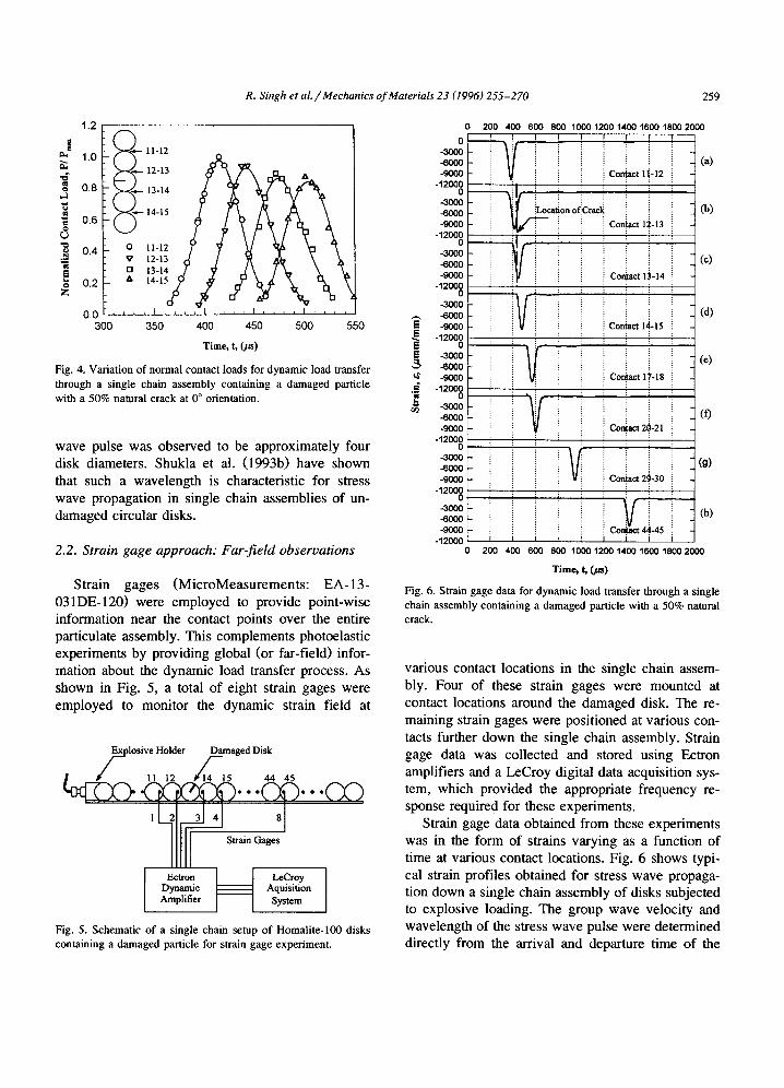
Fig. 6. Strain gage data for dynamic load transfer through a single chain assembly containing a damaged panicle with a 50% natural crack.
various contact locations in the single chain assem- bly. Four of these strain gages were mounted at contact locations around the damaged disk. The re- maining strain gages were positioned at various con- tacts further down the single chain assembly. Strain gage data was collected and stored using Ectron amplifiers and a LeCroy digital data acquisition sys- tem, which provided the appropriate frequency re- sponse required for these experiments.
Strain gage data obtained from these experiments was in the form of strains varying as a function of time at various contact locations. Fig. 6 shows typi- cal strain profiles obtained for stress wave propaga- tion down a single chain assembly of disks subjected to explosive loading. The group wave velocity and wavelength of the stress wave pulse were determined directly from the arrival and departure time of the
260 R. Singh et al. / Mechanics of Materials 23 (1996) 255-270
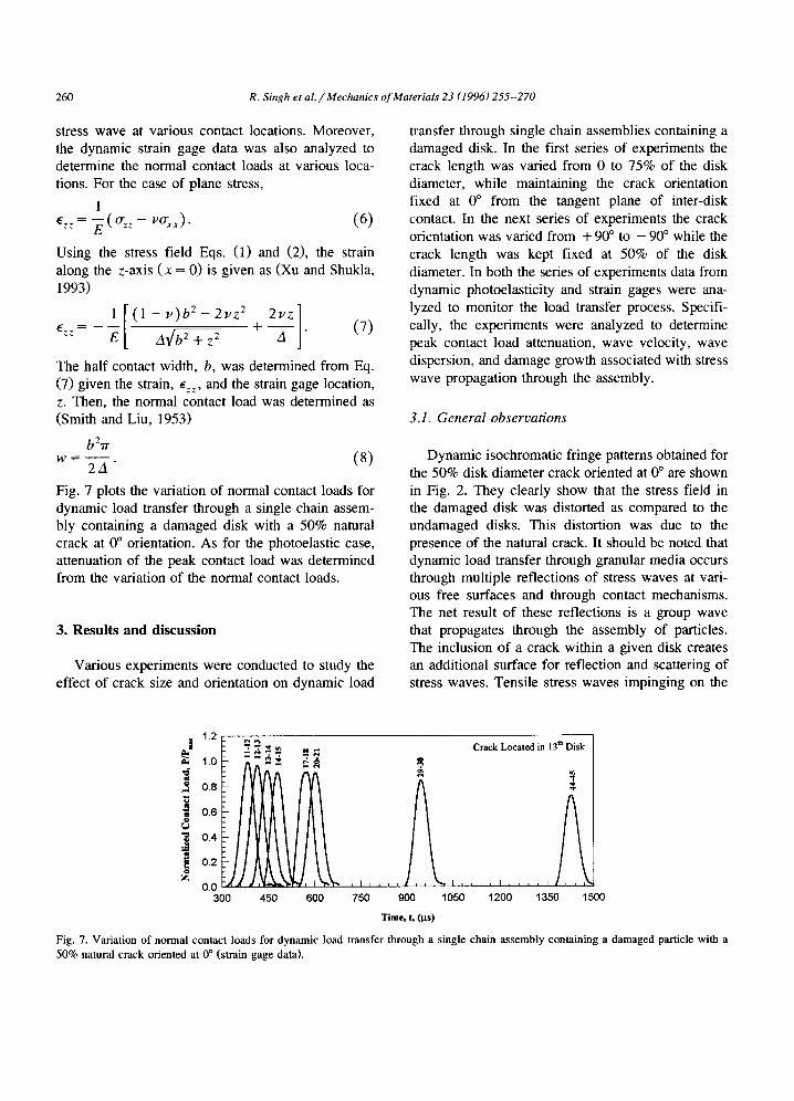
stress wave at various contact locations. Moreover, the dynamic strain gage data was also analyzed to determine the normal contact loads at various loca- tions. For the case of plane stress,
1 ezz = ~ ( ~ z - v°-xx)" (6)
Using the stress field Eqs. (1) and (2), the strain along the z-axis (x = 0) is given as (Xu and Shukla, 1993)
1 [ ( l - t , ) b 2 - 2~ ' z 2 2~,z
ezz = E [ A ~ + Z 2 + ~ - (7)
The half contact width, b, was determined from Eq. (7) given the strain, ezz, and the strain gage location, z. Then, the normal contact load was determined as (Smith and Liu, 1953)
b27r w = - - (8)
2A
Fig. 7 plots the variation of normal contact loads for dynamic load transfer through a single chain assem- bly containing a damaged disk with a 50% natural crack at 0 ° orientation. As for the photoelastic case, attenuation of the peak contact load was determined from the variation of the normal contact loads.
3. Resul ts and discuss ion
Various experiments were conducted to study the effect of crack size and orientation on dynamic load
transfer through single chain assemblies containing a damaged disk. In the first series of experiments the crack length was varied from 0 to 75% of the disk diameter, while maintaining the crack orientation fixed at 0 ° from the tangent plane of inter-disk contact. In the next series of experiments the crack orientation was varied from + 90 ° to - 90 ° while the crack length was kept fixed at 50% of the disk diameter. In both the series of experiments data from dynamic photoelasticity and strain gages were ana- lyzed to monitor the load transfer process. Specifi- cally, the experiments were analyzed to determine peak contact load attenuation, wave velocity, wave dispersion, and damage growth associated with stress wave propagation through the assembly.
3.1. General observations
Dynamic isochromatic fringe patterns obtained for the 50% disk diameter crack oriented at 0 ° are shown in Fig. 2. They clearly show that the stress field in the damaged disk was distorted as compared to the undamaged disks. This distortion was due to the presence of the natural crack. It should be noted that dynamic load transfer through granular media occurs through multiple reflections of stress waves at vari- ous free surfaces and through contact mechanisms. The net result of these reflections is a group wave that propagates through the assembly of particles. The inclusion of a crack within a given disk creates an additional surface for reflection and scattering of stress waves. Tensile stress waves impinging on the
i 1.2 =,~ ,"t
. 1.0 =;~"~ =
0.8
0.6
0.4
~ 0.2
0 . 0 , , I . . . . 300 450 600 750
Crack Located in 13 th Disk
L I , , , , 900 1050
T i m e , t, (Its) 1200 1350 1500
Fig. 7. Variation of normal contact loads for dynamic load transfer through a single chain assembly containing a damaged particle with a 50% natural crack oriented at 0 ° (strain gage data).
R. Sing h et al. / Mechanics of Materials 23 (1996) 255-270 261
crack surface suffer scattering and reflection, while compressive stress waves close the natural crack and are transmitted. Moreover, the transmittance (or scat- tering) of shear stress waves is govemed by the friction between the two crack surfaces and the sign of the normal component of load, i.e. tensile or compressive. Thus, stresses are only partially trans- mitted across the crack surface. This results in the discontinuity in the fringe contours across the crack surfaces, as seen in Fig. 2. Scattering of the stress waves at the crack surface can also result in the refection of energy back up the chain in the form of a back reflected pulse. Additionally, a portion of the stress wave could be momentarily trapped in the damaged disk due to the increased multiple reflec- tions. This ' trapping' results in an elongation of the stress wave pulse (as seen in frame 19 in Fig. 2) and
in local changes in the contact loads. An additional effect due to the presence of a crack
is diffraction of stress waves at the tip of the natural crack. These diffractions result in crack tip loading, which could be sufficient to cause damage growth. Such damage growth would dissipate energy in the formation of new surfaces and also cause a change in the microstructural fabric of the particulate assembly. However, in the 0 ° orientation experiments no such crack growth was observed.
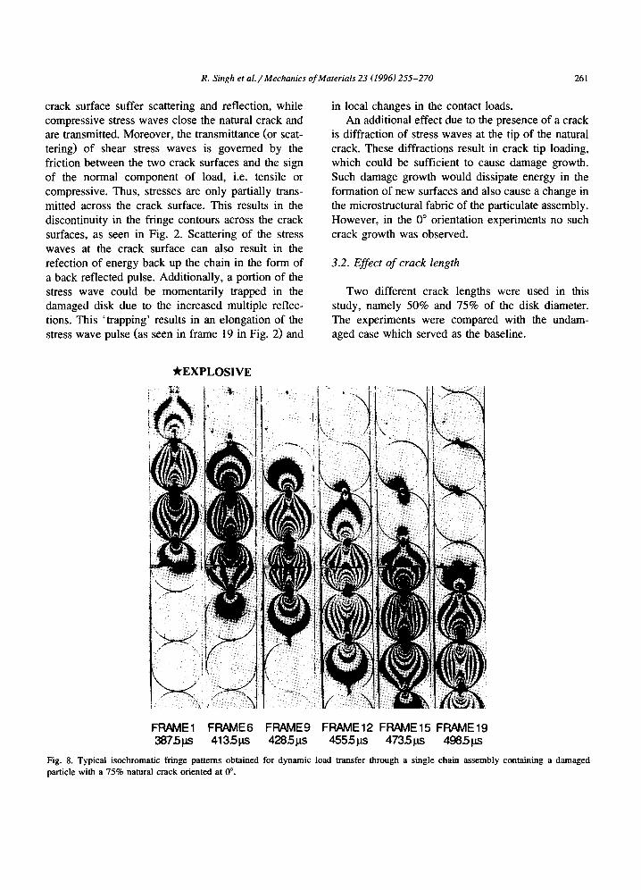
3.2. Effect of crack length
Two different crack lengths were used in this study, namely 50% and 75% of the disk diameter. The experiments were compared with the undam- aged case which served as the baseline.
~EXPLOSIVE
FRAME1 FRAME6 FRAME9 FRAME12 FRAME15 FRAME19 3875t~s 413.5ps 4285ps 4555ps 47351as 498,5ps
Fig. 8. Typical isochromatic fringe patterns obtained for dynamic load transfer through a single chain assembly containing a damaged particle with a 75% natural crack oriented at 0 °.
262 R. Singh et aL / Mechanics of Materials 23 (1996) 255-270
1.2 ( , ~ 0 11-12
V 12-13 E 11-12 . j ~ ~ 0 13-14 1.0
o,: ' 04 o
0.2 7 %
300 350 400 450 500 550
Time, t, (,us)
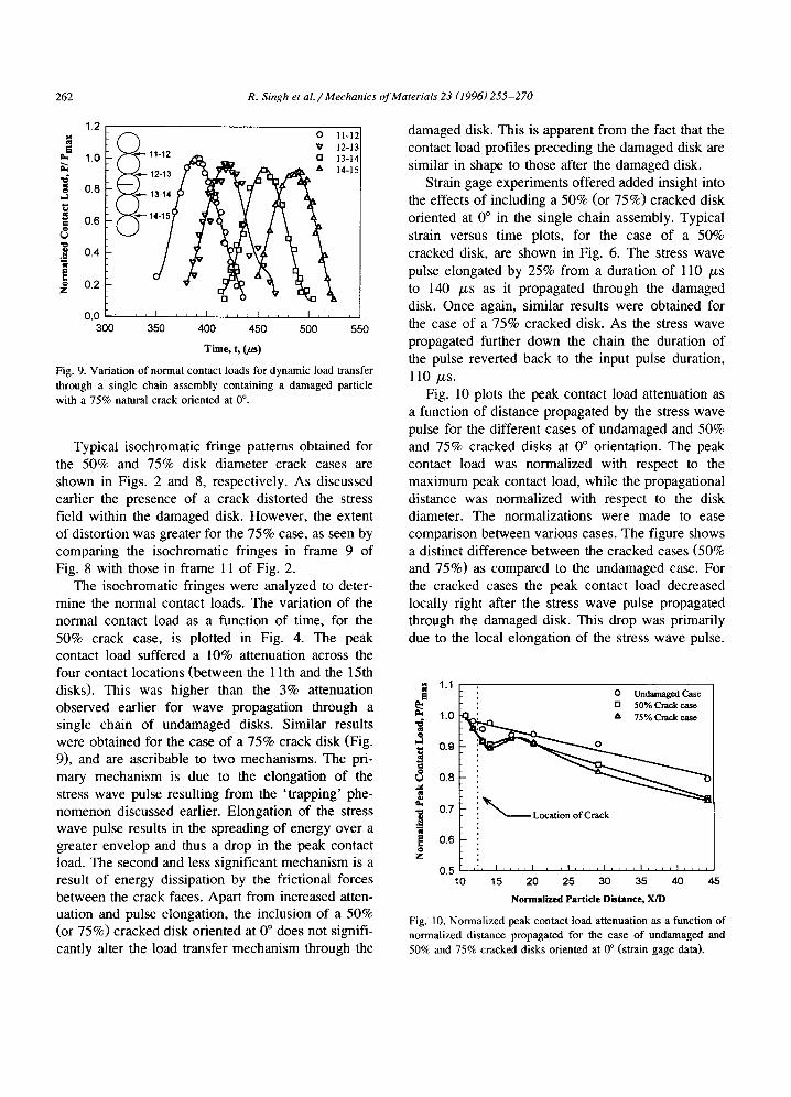
Fig. 9. Variation of normal contact loads for dynamic load transfer through a single chain assembly containing a damaged particle with a 75% natural crack oriented at 0 °.
Typical isochromatic fringe patterns obtained for the 50% and 75% disk diameter crack cases are shown in Figs. 2 and 8, respectively. As discussed earlier the presence of a crack distorted the stress field within the damaged disk. However, the extent of distortion was greater for the 75% case, as seen by comparing the isochromatic fringes in frame 9 of Fig. 8 with those in flame 11 of Fig. 2.
The isochromatic fringes were analyzed to deter- mine the normal contact loads. The variation of the normal contact load as a function of time, for the 50% crack case, is plotted in Fig. 4. The peak contact load suffered a 10% attenuation across the four contact locations (between the 1 lth and the 15th disks). This was higher than the 3% attenuation observed earlier for wave propagation through a single chain of undamaged disks. Similar results were obtained for the case of a 75% crack disk (Fig. 9), and are ascribable to two mechanisms. The pri- mary mechanism is due to the elongation of the stress wave pulse resulting from the 'trapping' phe- nomenon discussed earlier. Elongation of the stress wave pulse results in the spreading of energy over a greater envelop and thus a drop in the peak contact load. The second and less significant mechanism is a result of energy dissipation by the frictional forces between the crack faces. Apart from increased atten- uation and pulse elongation, the inclusion of a 50% (or 75%) cracked disk oriented at 0 ° does not signifi- cantly alter the load transfer mechanism through the
damaged disk. This is apparent from the fact that the contact load profiles preceding the damaged disk are similar in shape to those after the damaged disk.
Strain gage experiments offered added insight into the effects of including a 50% (or 75%) cracked disk oriented at 0 ° in the single chain assembly. Typical strain versus time plots, for the case of a 50% cracked disk, are shown in Fig. 6. The stress wave pulse elongated by 25% from a duration of 110 /zs to 140 /zs as it propagated through the damaged disk. Once again, similar results were obtained for the case of a 75% cracked disk. As the stress wave propagated further down the chain the duration of the pulse reverted back to the input pulse duration, 110 /zs.
Fig. 10 plots the peak contact load attenuation as a function of distance propagated by the stress wave pulse for the different cases of undamaged and 50% and 75% cracked disks at 0 ° orientation. The peak contact load was normalized with respect to the maximum peak contact load, while the propagational distance was normalized with respect to the disk diameter. The normalizations were made to ease comparison between various cases. The figure shows a distinct difference between the cracked cases (50% and 75%) as compared to the undamaged case. For the cracked cases the peak contact load decreased locally right after the stress wave pulse propagated through the damaged disk. This drop was primarily due to the local elongation of the stress wave pulse.
1.1
~ 0.9
{J 0.8 .h¢ =1
0.7
E 0.6
0.5 10
: o Undamaged Case : [] 50% Crack case
"if-, , 15 20 25 30 35 40 45
Normalized Partide Distance, X/D
Fig. 10. Normalized peak contact load attenuation as a function of normalized distance propagated for the case of undamaged and 50% and 75% cracked disks oriented at 0 ° (strain gage data).
R. Singh et al. / Mechanics of Materials 23 (1996) 255-270 263
With further propagation the peak contact load in- creased as the elongated pulse regrouped into a pulse with the same duration as the input stress wave pulse. However, overall attenuation for the damaged cases (50% and 75%) was greater than that for the undamaged case. As shown in Fig. 10, the peak contact load attenuation increased from 20%, for the undamaged case, to 28% for the 75% cracked case for 1 m distance of travel by the stress wave pulse (between the 1 lth and the 45th disks).
The group wave velocity of the stress wave pulse was not affected by the presence of a damaged disk in the single chain assembly. The average velocity for both the damaged and undamaged cases was determined to be 1000 m / s . Also, back reflected pulses were absent and no energy was returned up
the single chain assembly due to the presence of a damaged disk.
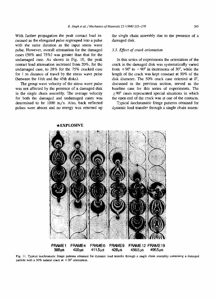
3.3. Effect of crack orientation
In this series of experiments the orientation of the crack in the damaged disk was systematically varied from + 90 ° to - 9 0 ° in increments of 30 °, while the length of the crack was kept constant at 50% of the disk diameter. The 50% crack case oriented at 0 °, discussed in the previous section, served as the baseline case for this series of experiments. The +90 ° cases represented special situations in which the open end of the crack was at one of the contacts.
Typical isochromatic fringe patterns obtained for dynamic load transfer through a single chain assem-
-kEXPLOSIVE
FR/~E1 FRAME4 FRAME6 FRAME9 FRAME12 FRAME19 388ps 400 I.IS 4115ps 428~u.s 4565 ps 496.5 t.ls
Fig. 11. Typical isochromatic fringe patterns obtained for dynamic load transfer through a single chain assembly containing a damaged particle with a 50% natural crack at + 30 ° orientation.
264 R. Singh et a l . / Mechanics of Materials 23 (1996) 255-270
bly containing a damaged disk with 50% crack ori- ented at + 30 ° are shown in Fig. 11. A comparison of Figs. 2 and 11 demonstrates that the crack ori- ented at + 30 ° influenced the load transfer process to a much greater degree than the crack oriented at 0 °. The primary distinction was crack tip loading and subsequent crack growth for + 30 ° orientation case. As shown in frames 1 and 4 in Fig. 11, the isochro- matic fringes surrounding the crack tip correspond to a predominantly mode-II loading of the crack tip. This shear loading of the crack caused the crack tip to initiate and subsequently grow. Shear loading dominated crack tip initiation causing the crack to kink sharply and grow towards the contact following the damaged disk, parallel to the direction of stress wave propagation. Once the crack had started to grow the crack tip loading was predominantly mode-I in nature, as demonstrated in frame 9 of Fig. 11. Thereafter, the crack did not curve or kink and kept growing towards the contact following the damaged disk. The average crack tip velocity was determined to be --250 m / s which represents a typical value for dynamic crack propagation in Homalite-100. Post-mortem analysis of the fracture surface revealed a smooth surface, which corresponds well with the observed crack speed for this material. Crack growth was initiated early in the process of interaction of the stress wave pulse and the damaged disk. In fact, the crack had propagated through the entire disk even before the trailing edge of the stress wave pulse had left the damaged disk.
Crack growth resulted in a fragmentation of the damaged disk and hence in a rearrangement of the microstructure of the single chain assembly. As a result of disk fragmentation a portion of the damaged disk broke free and no longer contributed to the load transfer path. Moreover, fragmentation also resulted in the redirection of the energy in the form of side loads. The side loads, as shown in frames 9, 12 and 19 in Fig. 11, resulted in energy transfer to the side supporting walls and hence in an energy loss from the stress wave pulse propagating down the single chain assembly. The rearrangement of microstructure would also play an important role in the load transfer process if the single chain assembly was subjected to another explosive loading.
Stress wave propagation through a single chain assembly containing a 50% cracked disk oriented at
-30 , +60 °, or - 6 0 ° also exhibited similar phe- nomenon as the + 30 ° orientation case. As before, the stress wave loaded the crack tip and caused crack initiation and subsequent growth. The crack kinked sharply upon initiation and then grew parallel to the direction of stress wave propagation, either in the direction of the preceding contact or the following depending on orientation of the original crack. For the +30 ° and +60 ° orientations the crack propa- gated towards the following contact. Whereas for the - 3 0 ° and - 6 0 ° orientations the crack propagated towards the preceding contact. The direction of kink- ing and crack propagation was a function of the nature of shear loading at the crack tip, which in tum depended on the orientation of the pre-existing crack. This relationship between kinking direction and crack orientation is discussed in greater detail in the fol- lowing sub-section. For all the +30 ° and +60 ° orientations crack growth was initiated early in the process of interaction of the stress wave pulse and the average crack tip velocity was -- 250 m/s .
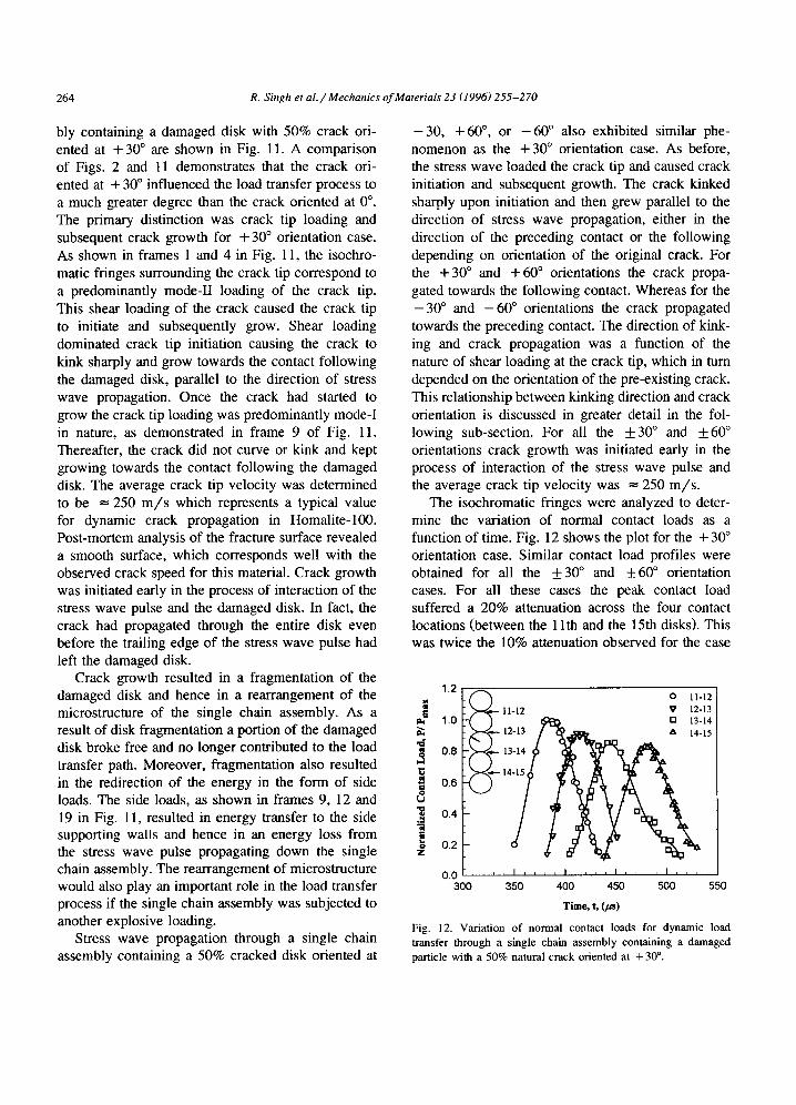
The isochromatic fringes were analyzed to deter- mine the variation of normal contact loads as a function of time. Fig. 12 shows the plot for the + 30 ° orientation case. Similar contact load profiles were obtained for all the ___30 ° and _+60 ° orientation cases. For all these cases the peak contact load suffered a 20% attenuation across the four contact locations (between the 1 lth and the 15th disks). This was twice the 10% attenuation observed for the case
1.2 • r -~ 0 11-12 =
11-12 V 12-13 f 1.0 " " ~ [] 13-14 . ~--~-- 12-13 ~ ,,~ & 14-15
~o 0.6
~ 0.4
~ 0.2 Z
300 350 400 450 500 550
T i m e , t, (/as)
Fig. 12. Variation of normal contact loads for dynamic load transfer through a single chain assembly containing a damaged particle with a 50% natural crack oriented at + 30 °.
R. Singh et al. / Mechanics of Materials 23 (1996) 255-270 265
of a 50% cracked disk oriented at 0 °. The increase in attenuation was primarily due to the elongation of the stress wave pulse as it propagated through the damaged disk. Additionally, some of the energy was transferred to the side supports in the form of side loads. These side loads were determined to be as high as 15% of the peak contact load. Some of the energy would be expected to be dissipated in the fracturing of the damaged disk. However, Singh et al. (1996) have shown that the energy dissipated in the fracture process represents a negligible fraction of the energy associated with the stress wave pulse.
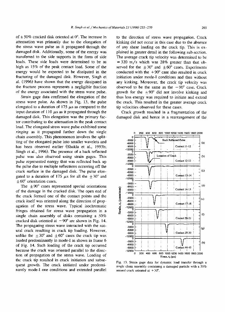
Strain gage data confirmed the elongation of the stress wave pulse. As shown in Fig. 13, the pulse elongated to a duration of 175/~s as compared to the input duration of 110 p~s as it propagated through the damaged disk. This elongation was the primary fac- tor contributing to the attenuation in the peak contact load. The elongated stress wave pulse exhibited some ringing as it propagated further down the single chain assembly. This phenomenon involves the split- ting of the elongated pulse into smaller wavelets and has been observed earlier (Shukla et al., 1993b; Singh et al., 1996). The presence of a back reflected pulse was also observed using strain gages. This pulse represented energy that was reflected back up the pulse due to multiple reflections occurring off the crack surface in the damaged disk. The pulse elon- gated to a duration of 175 /~s for all the +30 ° and + 60 ° orientation cases.
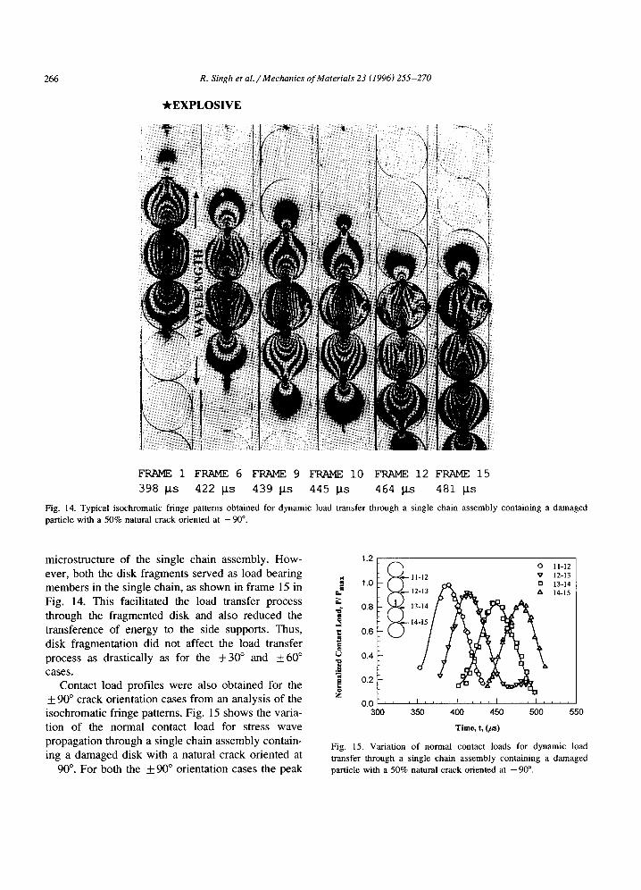
The + 90 ° cases represented special orientations of the damage in the cracked disk. The open end of the crack formed one of the contact points and the crack itself was oriented along the direction of prop- agation of the stress wave. Typical isochromatic fringes obtained for stress wave propagation in a single chain assembly of disks containing a 50% cracked disk oriented at - 9 0 ° are shown in Fig. 14. The propagating stress wave interacted with the nat- ural crack resulting in crack tip loading. However, unlike the + 30 ° and + 60 ° cases the crack tip was loaded predominantly in mode-I as shown in frame 6 of Fig. 14. Such loading of the crack tip occurred because the crack was oriented parallel to the direc- tion of propagation of the stress wave. Loading of the crack tip resulted in crack initiation and subse- quent growth. The crack initiated under predomi- nantly mode-I one conditions and extended parallel
to the direction of stress wave propagation. Crack kinking did not occur in this case due to the absence of any shear loading on the crack tip. This is ex- plained in greater detail in the following sub-section. The average crack tip velocity was determined to be = 320 m / s which was 28% greater than that ob- served for the + 30 ° and + 60 ° cases. Experiments conducted with the + 90 ° case also resulted in crack initiation under mode-I conditions and thus without any kinking. Moreover, the crack tip velocity was observed to be the same as the - 9 0 ° case. Crack growth for the +90 ° did not involve kinking and thus less energy was required to initiate and extend the crack. This resulted in the greater average crack tip velocities observed for these cases.
Crack growth resulted in a fragmentation of the damaged disk and hence in a rearrangement of the
200 400 600 800 1000 1200 1400 1600 1800 2000 I I I I i I 0 . . . . . . ,
-6000 -3000 - - ~ ~ a c ~ Refl(~cted Pulse :: (a)
-9000 ~ Contact 1 t- 12 -12000
-6000 .9ooo coo ct 12.13
-12000 o ~: ,.,,,~: ~ - - i
-3000 ~ i ~ i i (c) -6000 : : -9000 .. i :: Contact 1)-14
-12000 o . . ~ :
-3000 -6000 (d)
Contact 14-15 ~9000 -12000
o -3ooo (c) .-6000
¢S -9000 . i Coniact 17-18 ..= -1200~ :
r,~ -3000 -6oo0 ~ (O -9000 i Contact 20-21
-12000 : : : 0 '
-3000 (g) -6O0O -9000 Con}act~
-12000
-6000"3000 ~ -I (h)
.,0oo -12000 i Con
0 200 400 600 800 1000 1200 1400 1600 1800 2000 T i m e , t, (ps )
Fig. 13. Strain gage data for dynamic load transfer through a single chain assembly containing a damaged particle with a 50% natural crack oriented at + 30 °.
266 R. Singh et al. / Mechanics of Materials 23 (1996) 255-270
*EXPLOSIVE
FRAME 1 FRAME 6 FRAME 9 FRAME i0 FRAME 12 FRAME 15
398 J/s 422 I/s 439 I/s 445 Its 464 I/s 481 Its
Fig. 14. Typical i sochromat ic f r inge pat terns obta ined for dynamic load t ransfer th rough a single chain assembly conta in ing a damaged
part icle with a 50% natural c rack oriented at - 9 0 °.
microstructure of the single chain assembly. How- ever, both the disk fragments served as load bearing members in the single chain, as shown in frame 15 in Fig. 14. This facilitated the load transfer process through the fragmented disk and also reduced the transference of energy to the side supports. Thus, disk fragmentation did not affect the load transfer process as drastically as for the + 3 0 ° and + 6 0 ° cases.
Contact load profiles were also obtained for the __+ 90 ° crack orientation cases from an analysis of the isochromatic fringe patterns. Fig. 15 shows the varia- tion of the normal contact load for stress wave propagation through a single chain assembly contain- ing a damaged disk with a natural crack oriented at - 9 0 °. For both the + 90 ° orientation cases the peak
1.2 o 11-12
i 1.0 11-12 ~ 12-13 ~ ' ~ ~eb 13-14
0,,, ~ 12-13 h, 14-15
0.8 13-14
0.4
0.2
0.0 , , , I . . . . I . . . . I , , , I . . . .
300 350 400 450 500 550
T i m e , t, (/m)
Fig. 15. Variat ion o f normal contac t loads for dynamic load
t ransfer through a single chain assembly conta in ing a damaged part icle with a 50% natural c rack oriented at - 9 0 °.
R. Singh et al. / Mechanics of Materials 23 (1996) 255-270 267
contact load attenuation was determined to be 8% across four contact points. This attenuation was much lower than that observed for the other crack orienta- tion experiments, and even lower than that observed for a 50% crack oriented at 0 °. This was due to the more direct transmission of the stress wave pulse through the damaged disk as the crack surface was parallel to the direction of stress wave propagation.
Strain gage experiments were also conducted on long single chain assemblies containing 50% cracked disks oriented at + 90 °. These experiments demon- strated that there was no appreciable elongation of the stress wave pulse as it propagated through the damaged disk. This lack of pulse elongation was also a factor contributing to the lower peak contact load attenuation observed for these two special crack orientations.
3.4. Damage growth in naturally cracked particles
Crack initiation and subsequent growth was ob- served for all the + 30 °, + 60 ° and + 90 ° orientation cases. Post-failure photographs of the damaged disks are shown in Fig. 16. As shown, the crack grew parallel to the direction of the stress wave propaga- tion, either in the direction of the preceding contact or the following depending on orientation of the original crack. For the -+ 30 ° and + 60 ° orientation
f 1 ' /
Fig. 16. Post-failure photographs of the damaged disks showing crack initiation and subsequent growth (left to right and top to bottom: + 30 °, - 30 °, + 60 °, and - 60°).
(a) (b) (c) (d) Fig. 17. Damage growth in cracks subjected to dynamic loading by the propagating stress wave. (a) Shear loading of + 30 ° and + 6 0 ° cracks; (b) tensile loading of _+90 ° cracks; (c) upward kinking in - 30 ° and - 600 cracks; and (d) downward kinking in + 30 ° and + 60 ° cracks.
cases, crack initiation was also associated with sharp kinking. Kinking was not observed for the +90 ° orientation cases.
Consider stress wave propagation through a dam- aged disk. Since the wavelength of the loading pulse was four times greater than the diameter of the disk we can consider the disk to be subjected to dynamic loads at the two contact points, as shown in Fig. 17. This dynamic axial compression of the cracked disk loads the crack either in shear or in tension depend- ing on the relative orientation of the natural crack. Thus, the _+30 ° and _+60 ° orientation cases were loaded predominantly in shear accompanied by crack face sliding, as shown in Fig. 17(a), while the _+90 ° orientation cases were loaded in pure tension, as shown in Fig. 17(b). It was also apparent that no crack tip loading would occur if the crack was perpendicular to the longitudinal axis of the disk. This explained the absence of crack tip loading for the 50% (and 75%) crack oriented at 0 °.
Quasi-static experiments by Brace and Bombo- lakis (1963) and by Hoek and Bieniawksi (1965) on glass plates containing cracks oriented at certain angles with respect to the direction of axial compres- sion showed that the relative sliding of the faces of the pre-crack produced, at the tip of these pre-cracks, small tension cracks which kinked at sharp angles from the sliding plane. More recently, Nemat-Nasser and Horii (1982) and Horii and Nemat-Nasser (1982) analytically and experimentally investigated the axial compression of plates containing flaws oriented at an angle with respect to the compression direction. They showed that, under axial compression, tension cracks nucleated at the tips of the sliding pre-existing crack
268 R. Singh et a l . / Mechanics of Materials 23 (1996) 255-270
and extended along the maximum compressive stress direction.
The crack kinking observed in the +30 ° and +60 ° orientations was a result of a tensile crack being nucleated at the tip of the sliding pre-existing crack. In accordance with the analytical work of Nemat-Nasser and Horii (1982), this tensile crack grew parallel to the direction of axial compression. The direction of kinking was governed by the rela- tive sliding of the crack faces. Thus, the - 3 0 ° and - 6 0 ° cracks kinked upward, as shown in Fig. 17(c), while the + 30 ° and + 60 ° cracks kinked downward, as shown in Fig. 17(d). The + 90 ° cracks were not subjected to crack face sliding and thus no kinking was observed.
Crack initiation (and subsequent growth) would occur if the axial compression sufficiently loaded the crack tip. This loading would primarily depend upon the relative orientation of the natural crack. Thus, the probability of crack initiation (and subsequent growth) can be expressed as
einitiation = n([0[ - 0c), (9) where H ( . . . ) denotes the Heaviside step function, 0 is the orientation of the natural crack, and 0c is the critical angle of initiation. From experimental obser- vations,
0 ° < 0 c_< 30 ° , (10)
for the case of natural cracks.
3.5. Natural cracks versus open notches
Singh et al. (1996) have investigated dynamic load transfer through particulate assemblies contain- ing damaged particles where the damage was simu- lated by open notched flaws. The results of the current study indicate several similarities and differ- ences that exist between the cases of natural cracks and open notches. The open notch served as a greater barrier to stress wave propagation through the dam- aged disk than the closed natural crack. All the stress waves impinging on the open notch suffered scatter- ing and reflection, unlike the case of the closed crack. Thus, the open notch resulted in more reflec- tions of the stress wave within the damaged disk as compared to the natural crack. This caused a greater elongation of the stress wave pulse as it propagated
through the damaged disk. For example, the pulse elongated to a duration of 330 /zs as it propagated through a damaged disk containing a 75% disk diam- eter open notch oriented at 0 °, as compared to only 140 /xs when the damage was in the form of a natural crack. Increased pulse elongation resulted in greater local attenuation of the peak contact load Greater elongation also resulted in increased ringing and dissipation of secondary wavelets and thus in greater overall attenuation of the peak contact load. The open notch also resulted in more energy being sent back up the chain in the form of a back reflected pulse.
As for the 0 ° orientation cases, the angled cases also showed significant differences when the damage was simulated by an open notch, or by a natural crack. The notch resulted in greater elongation and attenuation of the stress wave pulse. Also, there were significant differences between the notched case and the natural crack case with regards to the crack initiation and propagation behavior. All the natural cracks oriented at angles other than 0 ° initiated early on in the stress wave-crack interaction process. Whereas, for the open notch cases, crack initiation and growth occurred only for the - 6 0 ° and _+ 90 ° orientations and that too only after most of the stress wave-pulse had already propagated through the dam- aged disk. For both types of flaws crack initiation occurred due to tensile reflections that impinge upon the crack tip. For the natural crack the crack tip was sharp and initiated easily. However, for the open notch the tip was blunt. Thus, initiation occurred only after most of the stress wave pulse had propa- gated through the damaged disk and the tensile reflections could dominate over the compressive stress wave pulse. The open notch oriented at 4-60 ° did not initiate and extend (unlike the open notch oriented at -60°) . This was due to the grazing incidence that the stress wave impinged at upon the -t-60 ° notch. The notch was loaded only from one side and the tensile stresses at the tip were not sufficient to warrant initiation and extension. This grazing incidence of the stress wave at 4- 60 ° notch caused shear waves to be reflected off towards the preceding contact. This resulted in a time dependent shear loading at the contact preceding the damaged disk. The shear load was oscillatory in nature and of a magnitude up to 20% of the peak normal contact
R. Singh et al. / Mechanics o f Materials 23 (1996) 255-270 269
load. Such shear loading was not observed in the case of a natural crack oriented at + 60 °.
4 . C l o s u r e
The results have shown that the presence of dam- aged disks significantly influenced dynamic load transfer through a one-dimensional particulate as- sembly. The effects of varying crack length and crack orientation on the load transfer process are summarized as follows:
(1) The stress field in the damaged disk was distorted as compared to the undamaged disks due to the presence of a flaw in the form of a closed natural crack. The crack reflected and scattered the tensile and (some) shear stress waves within the damaged disk. Scattering of the stress waves by the crack caused an elongation of the stress wave pulse as it propagated through the damaged disk, and also re- flected energy back up the chain in the form of a back reflected pulse. These two mechanisms con- tributed to a loca l attenuation in the peak contact load. The elongated stress wave pulse exhibited ring- ing and broke into separate wavelets. The secondary wavelets dissipated with further propagation con- tributing to increased over a l l attenuation.
(2) Results of varying the crack length from no-damage to 50% of the disk diameter (oriented at 0 °) showed that the pulse was elongated from 110 /.ts to 140 /zs as it propagated through the damaged disk. However, no appreciable change was noted as the crack length was further increased to 75% of the disk diameter. For the _ 30 ° and + 60 ° orientations the pulse elongated from 110 /zs to 170 /zs as it propagated through the damaged disk. However, no appreciable pulse elongation was observed for the + 9 0 ° orientation cases as the crack surfaces were oriented parallel to the direction of stress wave prop- agation and thus offered less resistance to the propa- gating stress wave.
(3) Stress wave diffraction at the tip of the natural crack loaded the crack tip and in certain cases re- suited in crack initiation and damage growth. Crack extension was observed for all cracks oriented at angles other than 0 °. For the _+ 30 ° and +_ 60 ° cases the crack v~as loaded predominantly in shear accom- panied by crack face sliding. This sliding resulted in
a kinked tensile crack to be nucleated at the tip of the pre-existing crack. After initiation the crack grew parallel to the direction of stress wave propagation without further kinking. For + 9 0 ° the crack was initiated under mode-I and kinking did not occur. Crack growth resulted in a fragmentation of the damaged disk and in a rearrangement of the mi- crostructure of the single chain assembly. For the _+ 30 ° and _+ 60 ° cases a portion of the damaged disk broke free and no longer contributed to the load transfer path. Moreover, fragmentation also resulted in the redistribution of the energy in the form of side loads. For the +_ 90 ° cases both the fragments still acted as load bearing members and the side loads were minimized.
(4) The average group wave velocity of the stress wave pulse was not affected due to the presence of a damaged disk. The group wave velocity was deter- mined to be -- 1000 m / s for all the various assem- blies studied.
(5) Damage in the form of a closed natural crack served as less of a barrier to the propagating stress wave as compared to an open notch. Thus, the closed natural crack resulted in less elongation of the stress wave pulse as it propagated through the damaged disk and thus in smaller local and far-field attenua- tions.
(6) Closed natural cracks were more conducive to crack initiation and subsequent growth than the open notches. Thus, all the _+ 30 °, _ 60 ° and + 90 ° orien- tation cases exhibited crack growth for the case of natural cracks, whereas only the - 6 0 ° and + 9 0 ° cases exhibited crack growth for the case of open notches. This difference was basically due to the presence of a sharp crack tip in the former cases, as compared to a blunt notch tip in the latter.
5 . N o t a t i o n
b /3 E
~:z z
f f~ h
N
- half contact width - friction factor - Young 's modulus - strain along the z-axis - tangential contact load - material fringe constant - specimen thickness - fringe order
270 R. Singh et al. / Mechanics of Materials 23 (1996) 255-2 70
v - P o i s s o n ' s r a t i o
P - n o r m a l c o n t a c t l o a d
R - contact radius of curvature O'1, O'2 -- principal s t r e s s
00xx, @z, ° ' x z - contact stress " / ' m a x - - maximum shear stress w - normal contact load per unit width
A c k n o w l e d g e m e n t s
The support of the United States Air Force Office of Scientific Research under grant numbers F49620- 93-1-0209 and F49620-93-1-0475 is gratefully ac- knowledged.
R e f e r e n c e s
Brace, W.F. and E.G. Bombolakis (1963), A Note on Brittle Crack Growth in Compression, J. Geophys. Res. 68, 3709- 3713.
Hoek, E. and Z.T. Bieniawksi (1965), Brittle Fracture Propaga- tion in Rock Under Compression, Int. J. Fract. Mech. 1, 137-155.
Horii, H. and S. Nemat-Nasser (1982), Compression-Induced Nonplanar Crack Extension with Application to Splitting, Ex- foliation and Rockburst, J. Geophys. Res. 90, 3105-3125.
Nemat-Nasser, S. and H. Horii (1982), Compression-Induced Nonplanar Crack Extension with Application to Splitting, Ex- foliation and Rockburst, J. Geophys. Res. 87, 6805-6821.
Rotherburg, L. and R.J. Bathurst (1992), Micromechanical Fea-
tures of Granular Assemblies With Plane Elliptical Particles, Geotechnique 1, 79-95.
Sadd, M.H., Q.M. Tai and A. Shukla (1993), Contact Law Effects on Wave Propagation in Particulate Materials" Using Distinct Element Modelling, Int. J. Nonlinear Mech. 28, 251-265.
Singh, R., A. Shukla and H. Zervas (1996), Effect of Flaws on the Stress Wave Propagation in Particulate Aggregates: Near and Far Field Obseroations, int. J. Solids Struct. 32, 2523-2546.
Shukla, A. and H. Nigam (1985), A Numerical-Experimental Analysis of the Contact Stress Problem, J. Strain Anal. 20(4), 241-245.
Shukla, A., M.H. Sadd, R. Singh, Q.M. Tai and S. Vishwanathan (1993a), Role of Particle Shape and Contact Profile on the Dynamic Response of Particulate Materials, Opt. Lasers Eng., 19, 99-119.
Shukla, A., M.H. Sadd, Y. Xu and Q.M. Tai (1993b), Influence of Loading Pulse Duration on Dynamic Load Transfer in a Simulated Granular Medium, J. Mech. Phys. Solids 41(11), 1795-1808.
Smith, J.O. and C.K. Liu (1953), Stresses due to Tangential and Normal Loads on an Elastic Solid with Applications to Some Contact Problems, J. Appl. Mech. 20, pp. 157-166.
Subhash, G., S. Nemat-Nasser, M.M. Mehrabadi and H.M. Shodja ( 1991), Experimental Investigation of Fabric-Stress Relations in Granular Materials, Mech. Mater. 11, 87-106.
Trent, B.C. (1989), Numerical Simulation of Wave Propagation Through Cemented Granular Materials, Wave Propagation in Granular Media, Proc. Winter Annual Meeting of ASME, 9-15.
Ting, J.M. and B.T. Corkum (1992), A Computational Laboratory for Discrete Element Geomechanics, J. Comput. Civil Eng. 6, 129-146.
Walton, K. (1987), The Effective Elastic Moduli of a Random Packing of Spheres, J. Mech. Phys. Solids, 35, 213-226.
Xu, Y. and A. Shukla (1993), Evaluation of Static and Dynamic contact Stresses in Simulated Granular Particles Using Strain Gages, ASTM J. Testing Eval. 21(3), 178-187.


![Engineering Fracture Mechanics · 2020. 6. 2. · lems, including: the crack growth with frictional contact [33], cohesive crack propagation [34–36], stationary and growing cracks](https://img.pdfslide.us/doc/110x75/60cb969feb2e1a3a012238f6/engineering-fracture-mechanics-2020-6-2-lems-including-the-crack-growth-with.jpg)