Embed Size (px)
Citation preview
Full AC-3 switching capacity
Double safety: additional auxiliary contact
Cost-saving installation up to 180 A
Snap-on mounting up to 40 A
IP66 protection up to 180 A
10.4
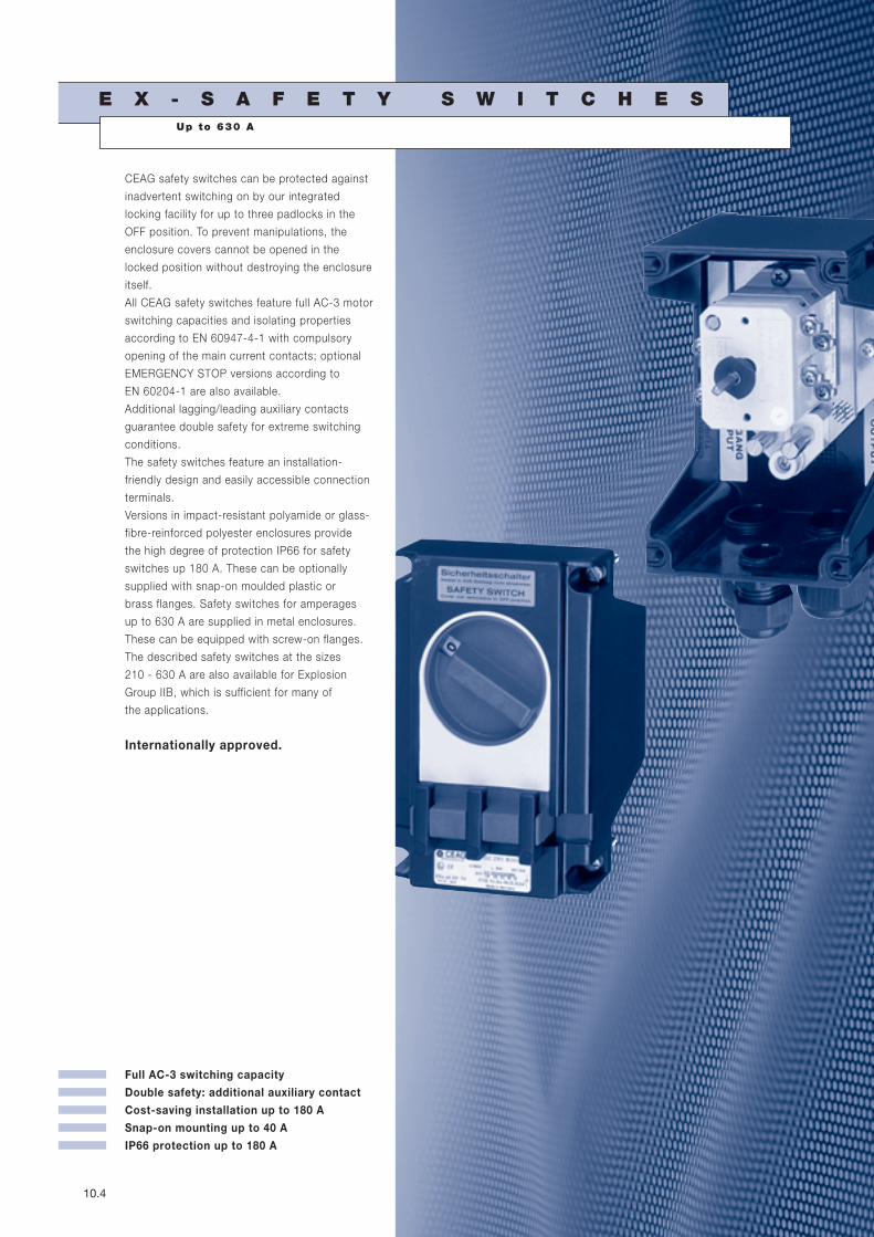
E X - S A F E T Y S W I T C H E S
CEAG safety switches can be protected against
inadvertent switching on by our integrated
locking facility for up to three padlocks in the
OFF position. To prevent manipulations, the
enclosure covers cannot be opened in the
locked position without destroying the enclosure
itself.
All CEAG safety switches feature full AC-3 motor
switching capacities and isolating properties
according to EN 60947-4-1 with compulsory
opening of the main current contacts; optional
EMERGENCY STOP versions according to
EN 60204-1 are also available.
Additional lagging/leading auxiliary contacts
guarantee double safety for extreme switching
conditions.
The safety switches feature an installation-
friendly design and easily accessible connection
terminals.
Versions in impact-resistant polyamide or glass-
fibre-reinforced polyester enclosures provide
the high degree of protection IP66 for safety
switches up 180 A. These can be optionally
supplied with snap-on moulded plastic or
brass flanges. Safety switches for amperages
up to 630 A are supplied in metal enclosures.
These can be equipped with screw-on flanges.
The described safety switches at the sizes
210 - 630 A are also available for Explosion
Group IIB, which is sufficient for many of
the applications.
Internationally approved.
Up to 630 A
I Ex-Safety switches I
C O O P E R C R O U S E - H I N D S G M B H 10.5
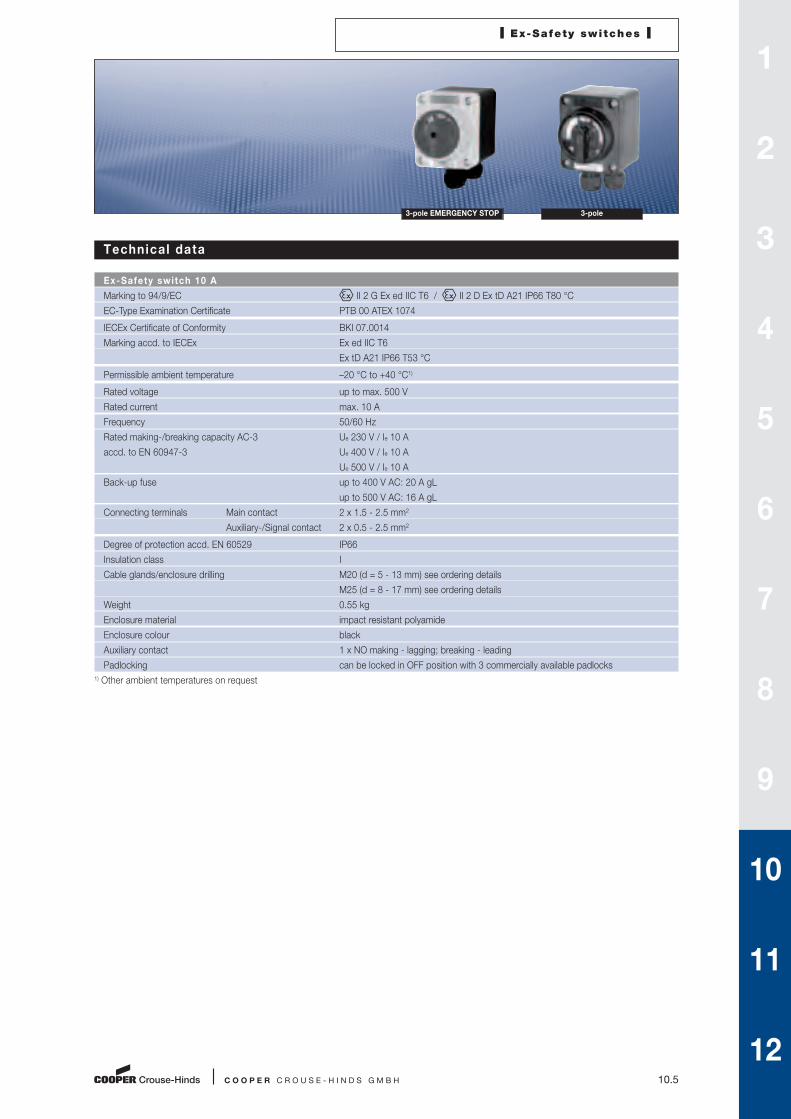
Technical data
Ex-Safety switch 10 A
Marking to 94/9/EC II 2 G Ex ed IIC T6 / II 2 D Ex tD A21 IP66 T80 °C
EC-Type Examination Certificate PTB 00 ATEX 1074
IECEx Certificate of Conformity BKI 07.0014
Marking accd. to IECEx Ex ed IIC T6
Ex tD A21 IP66 T53 °C
Permissible ambient temperature –20 °C to +40 °C1)
Rated voltage up to max. 500 V
Rated current max. 10 A
Frequency 50/60 Hz
Rated making-/breaking capacity AC-3 Ue 230 V / Ie 10 A
accd. to EN 60947-3 Ue 400 V / Ie 10 A
Ue 500 V / Ie 10 A
Back-up fuse up to 400 V AC: 20 A gL
up to 500 V AC: 16 A gL
Connecting terminals Main contact 2 x 1.5 - 2.5 mm2
Auxiliary-/Signal contact 2 x 0.5 - 2.5 mm2
Degree of protection accd. EN 60529 IP66
Insulation class I
Cable glands/enclosure drilling M20 (d = 5 - 13 mm) see ordering details
M25 (d = 8 - 17 mm) see ordering details
Weight 0.55 kg
Enclosure material impact resistant polyamide
Enclosure colour black
Auxiliary contact 1 x NO making - lagging; breaking - leading
Padlocking can be locked in OFF position with 3 commercially available padlocks
1) Other ambient temperatures on request
3-pole EMERGENCY STOP 3-pole
1
2
3
4
5
6
7
8
9
10
11
12
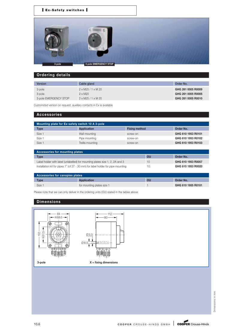
Dimensions
Dim
en
sio
ns i
n m
m
3-pole X = fixing dimensions
10.6 C O O P E R C R O U S E - H I N D S G M B H
I Ex-Safety switches I
3-pole 3-pole EMERGENCY STOP
Order ing detai ls
Version Cable gland Order No.
3-pole 2 x M25 / 1 x M 20 GHG 261 0005 R0009
3-pole 2 x M20 GHG 261 0005 R0005
3-pole EMERGENCY STOP 2 x M25 / 1 x M 20 GHG 261 0005 R0010
Customized version on request, auxiliary contacts in Ex ia available
Accessories
Mounting plate for Ex-safety switch 10 A 3-pole
Type Application Fixing method Order No.
Size 1 Wall mounting screw-on GHG 610 1953 R0101
Size 1 Pipe mounting screw-on GHG 610 1953 R0102
Size 1 Trellis mounting screw-on GHG 610 1953 R0103
Accessories for mounting plates
Type OU Order No.
Label holder with label (unlabelled) for mounting plates size 1, 2, 2A and 3 10 GHG 610 1953 R0057
Installation kit for pipes 1” (of 27 - 30 mm) for label holder for pipe mounting 10 GHG 610 1953 R0020
Accessories for canopies plates
Type Application OU Order No.
Size 1 for mounting plates size 1 1 GHG 610 1955 R0101
Please note that we can only deliver in the ordering units (OU) stated in the tables above
102
X61
.5
X68.584
80112
Ø 5.5
Ø 8.5

I Ex-Safety switches I
C O O P E R C R O U S E - H I N D S G M B H 10.7
6-pole EMERGENCY STOP 6-pole 3-pole EMERGENCY STOP 3-pole
Technical data
Ex-Safety switch 20 A
Marking to 94/9/EC II 2 G Ex ed ia IIC T6 / II 2 D Ex tD A21 IP66 T80 °C
EC-Type Examination Certificate PTB 99 ATEX 1161
IECEx Certificate of Conformity BKI 07.0012
Marking accd. to IECEx Ex ed ia IIC T6
Ex tD A21 IP66 T55 °C
Permissible ambient temperature –20 °C to +40 °C1)
Rated voltage up to max. 690 V
Rated current max. 20 A
Frequency 50/60 Hz
Rated making-/breaking capacity AC-3 Ue 230 V / Ie 20 A
accd. to EN 60947-3 Ue 400 V / Ie 20 A
Ue 500 V / Ie 10 A
Ue 690 V / Ie 10 A
Back-up fuse up to 400 V AC: 35 A gL
up to 500 V AC: 35 A gL
up to 690 V AC: 25 A gL
Connecting terminals Main contact 2 x 4 mm2
Auxiliary-/Signal contact 2 x 0.5 - 2.5 mm2
Insulation class I
Degree of protection accd. EN 60529 IP66
Cable glands/enclosure drilling M20 (d = 5 - 13 mm) see ordering details
M25 (d = 8 - 17 mm) see ordering details
M32 (d = 12 - 21 mm) see ordering details
Option: metal flange with thread
Weight 3-pole approx. 1.48 kg
6-pole approx. 2.43 kg
Enclosure material glass-fibre reinforced polyester
Enclosure colour black
Auxiliary contact 1 x NO making - lagging; breaking - leading
1 x NC (only 6-pole version) making - leading; breaking - lagging
Padlocking can be locked in OFF position with 3 commercially available padlocks
1) Other ambient temperatures on request
1
2
3
4
5
6
7
8
9
10
11
12

10.8 C O O P E R C R O U S E - H I N D S G M B H
I Ex-Safety switches I
Ordering detai ls
Version Cable entry Order No.
Safety switch 20 A 3-pole
Version with 1 auxiliary contact (NO)
3-pole 2 x M32 / 1 x M25 GHG 262 2301 R0001
3-pole EMERGENCY STOP 2 x M32 / 1 x M25 GHG 262 2301 R0002
Safety switch 20 A 4-pole
Version with 2 auxiliary contact (1 x NO; 1 x NC)
4-pole 2 x M20 GHG 262 2301 R0007
4-pole EMERGENCY STOP 2 x M32 / 1 x M25 GHG 262 2301 R0010
Safety switch 20 A 6-pole
Version with 2 auxiliary contact (1 x NO; 1 x NC)
6-pole 4 x M32 / 1 x M25 GHG 262 2601 R0001
6-pole 4 x M25 GHG 262 2601 R0005
6-pole EMERGENCY STOP 4 x M32 / 1 x M25 GHG 262 2601 R0002
Customized version on request, auxiliary contacts in Ex ia available
3-pole 3-pole EMERGENCY STOP 6-pole 6-pole EMERGENCY STOP
Accessories
Mounting plate for Ex-safety switch 20 A 3-pole
Type Application Fixing technique Order No.
Size 2 Wall mounting snap-on GHG 610 1953 R0104
Size 2 Pipe mounting snap-on GHG 610 1953 R0105
Size 2 Trellis mounting snap-on GHG 610 1953 R0106
Mounting plate for Ex-safety switch 20 A 6-pole
Type Application Fixing technique Order No.
Size 3 Wall mounting snap-on GHG 610 1953 R0118
Size 3 Pipe mounting snap-on GHG 610 1953 R0110
Size 3 Trellis mounting snap-on GHG 610 1953 R0118
Accessories for mounting plates
Type OU Order No.
Label holder with label (unlabelled) for mounting plates size 1, 2, 2A and 3 10 GHG 610 1953 R0057
Installation kit for pipes 1” (of 27 - 30 mm) for mounting plates for pipe mounting 10 GHG 610 1953 R0020
Accessories for canopies plates
Type Application OU Order No.
Size 2 for mounting plates size 2 1 GHG 610 1955 R0102
Size 2A for mounting plates size 2A 1 GHG 610 1955 R0103
Size 3 for pipe mounting plate size 3 vertical 1 GHG 610 1955 R0104
Size 3A for wall/trellis mounting plate size 3 vertical 1 GHG 610 1955 R0105
Size 3B for pipe mounting plate size 3 horizontal 1 GHG 610 1955 R0106
Please note that we can only deliver in the ordering units (OU) stated in the tables above
C O O P E R C R O U S E - H I N D S G M B H 10.9
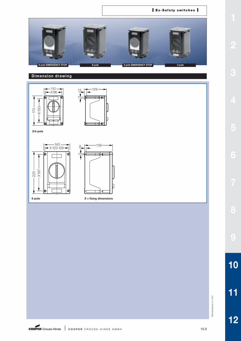
Dimension drawing
Dim
en
sio
ns i
n m
m
3/4-pole
6-pole X = fixing dimensions
I Ex-Safety switches I
6-pole EMERGENCY STOP 6-pole 3-pole EMERGENCY STOP 3-pole
X15
0
X96110
170
129
7
13
X19
7
X123-126140
225
156
7
8
1
2
3
4
5
6
7
8
9
10
11
12

10.10 C O O P E R C R O U S E - H I N D S G M B H
I Ex-Safety switches I
3-pole 3-pole EMERGENCY STOP 6-pole 6-pole EMERGENCY STOP
Technical data
Ex-Safety switch 40 A
Marking to 94/9/EC II 2 G Ex ed ia IIC T6 / II 2 D Ex tD A21 IP66 T80 °C
EC-Type Examination Certificate PTB 99 ATEX 1161
IECEx Certificate of Conformity BKI 07.0012
Marking accd. to IECEx Ex ed ia IIC T6
Ex tD A21 IP66 T53 °C
Permissible ambient temperature –20 °C to +40 °C
Rated voltage up to max. 690 V
Rated current max. 40 A
Frequency 50/60 Hz
Rated making-/breaking capacity AC-3 Ue 230 V / Ie 40 A
accd. to EN 60947-3 Ue 400 V / Ie 40 A
Ue 500 V / Ie 40 A
Ue 690 V / Ie 32 A
Back-up fuse up to 400 V AC: 80 A gL
up to 500 V AC: 80 A gL
up to 690 V AC: 63 A gL
Connecting terminals Main contact 2 x 16 mm2
Auxiliary-/Signal contact 2 x 4 mm2
Insulation class I
Degree of protection accd. EN 60529 IP66
Cable glands/enclosure drilling M25 (d = 8 - 17 mm) see ordering details
M40 (d = 16 - 28 mm) see ordering details
option: metal flange with thread
Weight 3-pole approx. 2.30 kg
4-pole approx. 2.75 kg
6-pole approx. 6.50 kg
Enclosure material glass-fibre reinforced polyester
Enclosure colour black
Auxiliary contact 1 x NO making - lagging; breaking - leading
1 x NC (only 6-pole version) making - leading; breaking - lagging
Padlocking can be locked in OFF position with 3 commercially available padlocks
1) Other ambient temperatures on request

I Ex-Safety switches I
C O O P E R C R O U S E - H I N D S G M B H 10.11
6-pole EMERGENCY STOP 6-pole 3-pole EMERGENCY STOP 3-pole
Order ing detai ls
Version Cable entry Order No.
Safety switch 40 A 3-pole
Version with 1 auxiliary contact (NO)
3-pole 2 x M40 / 1 x M25 GHG 263 2301 R0001
3-pole EMERGENCY STOP 2 x M40 / 1 x M25 GHG 263 2301 R0002
Safety switch 40 A 4-pole
Version with 2 auxiliary contact (1 x NO; 1 x NC)
4-pole 2 x M25 GHG 263 2301 R0007
Safety switch 40 A 6-pole
Version with 2 auxiliary contact (NO)
6-pole 4 x M40 / 1 x M25 GHG 263 0050 R0001
6-pole 4 x M25 GHG 263 0050 R0006
6-pole EMERGENCY STOP 4 x M40 / 1 x M25 GHG 263 0050 R0002
Customized version on request, auxiliary contacts in Ex ia available
Accessories
Mounting plate for Ex-safety switch 40 A 3-pole
Type Application Fixing technique Order No.
Size 3 Wall mounting snap-on GHG 610 1953 R0118
Size 3 Pipe mounting snap-on GHG 610 1953 R0110
Size 3 Trellis mounting snap-on GHG 610 1953 R0118
Mounting plate for Ex-safety switch 40 A 6-pole
Type Application Fixing technique Order No.
Size 3 2 x Pipe mounting screw-on1) GHG 610 1953 R0110
1) observe mounting distance
Accessories for mounting plates
Type OU Order No.
label for label holder and mounting plates size 4 and size 5 10 GHG 610 1953 R0011
Blanking plug for label holder size 4 and size 5 1 set = 1 each 10 GHG 610 1953 R0134
Snap-on for CEAG apparatus with 5.5 mm and 11 mm mounting feet 1 set = 4 each 10 GHG 610 1953 R0041
Installation kit for pipes 1" (of 27 - 30 mm) for pipe mounting 10 GHG 610 1953 R0020
Accessories for canopies plates
Type Application OU Order No.
Size 4 for mounting plates size 4 1 GHG 610 1955 R0107
Please note that we can only deliver in the ordering units (OU) stated in the tables above
1
2
3
4
5
6
7
8
9
10
11
12

10.12 C O O P E R C R O U S E - H I N D S G M B H
Dimension drawing
Dim
en
sio
ns i
n m
m
I Ex-Safety switches I
3-pole 3-pole EMERGENCY STOP 6-pole 6-pole EMERGENCY STOP
3/4-pole
6-pole X = fixing dimensions
X19
7
X123-126140
225
156
7
8
X 247271
X 24
727
1
275211
11 Ø 12
Ø 7

I Ex-Safety switches I
C O O P E R C R O U S E - H I N D S G M B H 10.13
6-pole EMERGENCY STOP 6-pole 3-pole EMERGENCY STOP 3-pole
Technical data
Ex-Safety switch 80 A
Marking to 94/9/EC II 2 G Ex ed ia IIC T6 / II 2 D Ex tD A21 IP66 T80 °C
EC-Type Examination Certificate PTB 00 ATEX 1091
IECEx Certificate of conformity BKI 07.0010
Marking accd. to IECEx Ex ed ia IIC T6
Ex tD A21 IP66 T53 °C
Permissible ambient temperature –20 °C to +40 °C
Rated voltage up to max. 690 V
Rated current max. 80 A
Frequency 50/60 Hz
Rated making-/breaking capacity AC-3 Ue 230 V / Ie 80 A
accd. to EN 60947-3 Ue 400 V / Ie 80 A
Ue 500 V / Ie 80 A
Ue 690 V / Ie 63 A
Back-up fuse up to 400 V AC: 160 A gL
up to 500 V AC: 160 A gL
up to 690 V AC: 125 A gL
Connecting terminals Main contact 2 x 25 mm2
Auxiliary-/Signal contact 2 x 4 mm2
Insulation class I
Degree of protection accd. EN 60529 IP66
Cable glands/enclosure drilling M25 (d = 8 - 17 mm) see ordering details
M32 (d = 12 - 21 mm) see ordering details
M50 (d = 21 - 35 mm) see ordering details
Option: metal flange with thread
Weight 3-pole approx. 6.5 kg
6-pole approx. 9.0 kg
Enclosure material glass-fibre reinforced polyester
Enclosure colour black
Auxiliary contact 1 x NO making - lagging; breaking - leading
1 x NC making - leading; breaking - lagging
Padlocking can be locked in OFF position with 3 commercially available padlocks
1) Other ambient temperatures on request
1
2
3
4
5
6
7
8
9
10
11
12

10.14 C O O P E R C R O U S E - H I N D S G M B H
I Ex-Safety switches I
3-pole 3-pole EMERGENCY STOP 6-pole 6-pole EMERGENCY STOP
Order ing detai ls
Version Cable entry Order No.
Safety switch 80 A 3-pole
Version with 2 auxiliary contact (1 x NO; 1 x NC)
3-pole 2 x M50 / 1 x M25 GHG 264 0020 R0001
3-pole EMERGENCY STOP 2 x M50 / 1 x M25 GHG 264 0020 R0002
Safety switch 80 A 6-pole
Version with 2 auxiliary contact (1 x NO; 1 x NC)
6-pole 4 x M50 / 1 x M25 GHG 264 0021 R0001
6-pole EMERGENCY STOP 4 x M50 / 1 x M25 GHG 264 0021 R0002
Customized version on request, auxiliary contacts in Ex ia available
Accessories
Mounting plate for Ex-safety switch 80 A 3- and 6-pole
Type Application Fixing technique Order No.
Size 3 2 x Pipe mounting screw-on1) GHG 610 1953 R0110
1) observe mounting distance
Accessories for mounting plates
Type OU Order No.
label for label holder and mounting plates size 4 and size 5 10 GHG 610 1953 R0011
Installation kit for pipes 1" (of 27 - 30 mm) for label holder for pipe mounting 10 GHG 610 1953 R0020
Please note that we can only deliver in the ordering units (OU) stated in the tables above
Dimension drawing
Dim
en
sio
ns i
n m
m
3/4-pole
6-pole X = fixing dimensions
X 247271
X 24
727
1
275211
11 Ø 12
Ø 7
X 247271
X 24
727
1
295211
11 Ø 12
Ø 7

I Ex-Safety switches I
C O O P E R C R O U S E - H I N D S G M B H 10.15
6-pole EMERGENCY STOP 6-pole 3-pole EMERGENCY STOP 3-pole
Technical data
Ex-Safety switch 125 A
Marking to 94/9/EC II 2 G Ex de IIC T6 / II 2 D Ex tD A21 IP66 T80 °C
EC-Type Examination Certificate 3-pole PTB 99 ATEX 1164
6-pole PTB 00 ATEX 1073
IECEx Certificate of Conformity BKI 07.0005
Marking accd. to IECEx Ex de IIC T6
Ex tD A21 IP66 T53 °C
Permissible ambient temperature –20 °C to +40 °C
Rated voltage up to max. 690 V
Frequency 50/60 Hz
Rated making-/breaking capacity AC-3 Ue 230 V / Ie 125 A
accd. to EN 60947-3 Ue 400 V / Ie 125 A
Ue 500 V / Ie 125 A
Ue 690 V / Ie 110 A
Back-up fuse up to 400 V AC: 200 A gL
up to 500 V AC: 200 A gL
up to 690 V AC: 160 A gL
Connecting terminals Main contact 3-pole 1 x 50/70 mm2
6-pole 6 x 95 mm2/2 x 95 mm2
Auxiliary-/Signal contact 2 x 4 mm2
Insulation class I
Degree of protection accd. EN 60529 IP66
Cable glands/enclosure drilling M25 (d = 8 - 17 mm) see ordering details
M40 (d = 16 - 28 mm) see ordering details
M63 (d = 27 - 48 mm) see ordering details
Option: metal flange with 2 x thread
Weight 3-pole approx. 16 kg
6-pole approx. 31 kg
Enclosure material 3-pole glass-fibre reinforced polyester
6-pole steel, powder-coated
Enclosure colour 3-pole black
6-pole white
Auxiliary contact 1 x NO making - lagging; breaking - leading
1 x NC making - leading; breaking - lagging
Padlocking can be locked in OFF position with 3 commercially available padlock
1) Other ambient temperatures on request
1
2
3
4
5
6
7
8
9
10
11
12

10.16 C O O P E R C R O U S E - H I N D S G M B H
I Ex-Safety switches I
3-pole 3-pole EMERGENCY STOP 6-pole 6-pole EMERGENCY STOP
Order ing detai ls
Version Cable entry Order No.
Safety switch 125 A
Version with 2 auxiliary contact (1 x NO; 1 x NC)
3-pole 2 x M63 / 1 x M25 GHG 265 0010 R0001
4-pole 2 x M40 GHG 265 0010 R0005
3-pole EMERGENCY STOP 2 x M63 / 1 x M25 GHG 265 0010 R0002
6-pole 4 x M63 / 1 x M25 EXKO 224716 K 0000
6-pole EMERGENCY STOP 4 x M63 / 1 x M25 EXKO 224726 K 0000
Customized version on request, auxiliary contacts in Ex ia available
Accessories
Mounting plate for Ex-safety switch 125 A 3-pole2)
Type Application Fixing technique Order No.
Size 3 2 x Pipe mounting screw-on1) GHG 610 1953 R0110
1) observe mounting distance
2) 2 pcs. necessary for mounting
Accessories for mounting plates
Type OU Order No.
Label holder with label (unlabelled) mounting plate size 1, 2, 2A and 3 10 GHG 610 1953 R0057
Installation kit for pipes 1" (of 27 - 30 mm) mounting plate for pipe mounting 10 GHG 610 1953 R0020
Please note that we can only deliver in the ordering units (OU) stated in the tables above

C O O P E R C R O U S E - H I N D S G M B H 10.17
Dim
en
sio
ns i
n m
m
Dimension drawing
3/4-pole
6-pole X = fixing dimensions
X 247271
X 52
054
4
275211
11 Ø 12
Ø 7
530X500450
8
X540
655
35
335
I Ex-Safety switches I
6-pole EMERGENCY STOP 6-pole 3-pole EMERGENCY STOP 3-pole
1
2
3
4
5
6
7
8
9
10
11
12
10.18 C O O P E R C R O U S E - H I N D S G M B H
I Ex-Safety switches I
3-pole 3-pole EMERGENCY STOP 6-pole 6-pole EMERGENCY STOP
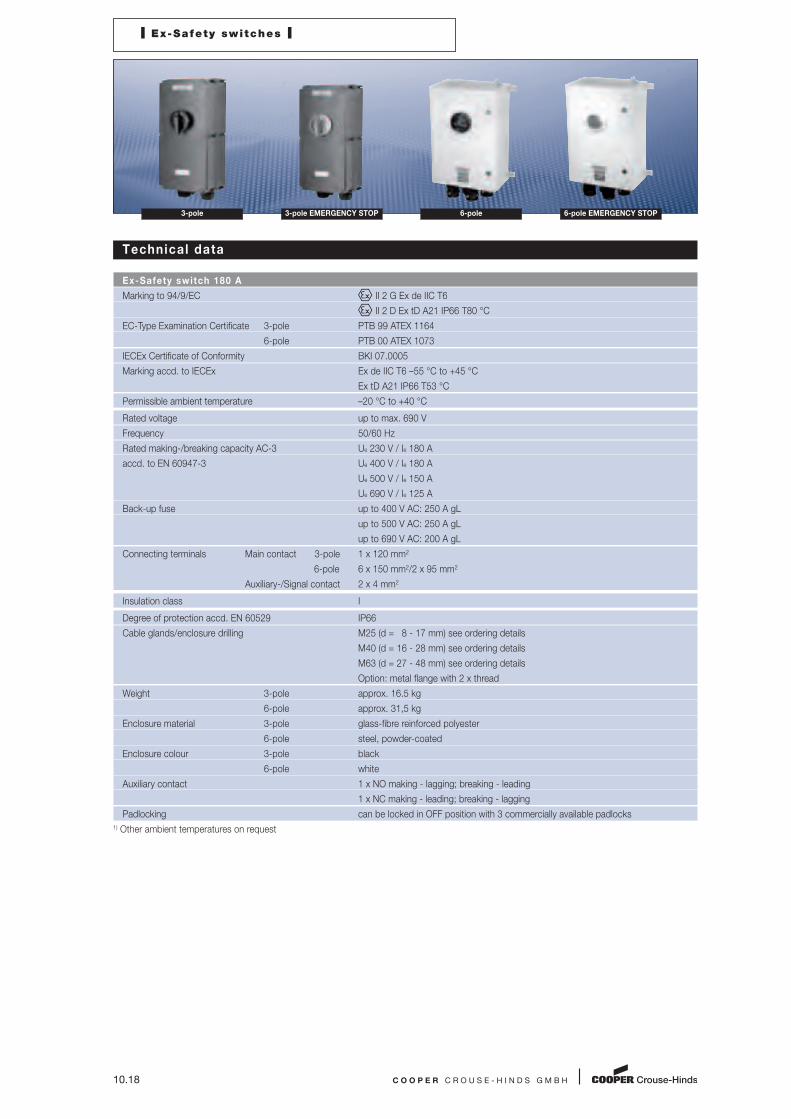
Technical data
Ex-Safety switch 180 A
Marking to 94/9/EC II 2 G Ex de IIC T6
II 2 D Ex tD A21 IP66 T80 °C
EC-Type Examination Certificate 3-pole PTB 99 ATEX 1164
6-pole PTB 00 ATEX 1073
IECEx Certificate of Conformity BKI 07.0005
Marking accd. to IECEx Ex de IIC T6 –55 °C to +45 °C
Ex tD A21 IP66 T53 °C
Permissible ambient temperature –20 °C to +40 °C
Rated voltage up to max. 690 V
Frequency 50/60 Hz
Rated making-/breaking capacity AC-3 Ue 230 V / Ie 180 A
accd. to EN 60947-3 Ue 400 V / Ie 180 A
Ue 500 V / Ie 150 A
Ue 690 V / Ie 125 A
Back-up fuse up to 400 V AC: 250 A gL
up to 500 V AC: 250 A gL
up to 690 V AC: 200 A gL
Connecting terminals Main contact 3-pole 1 x 120 mm2
6-pole 6 x 150 mm2/2 x 95 mm2
Auxiliary-/Signal contact 2 x 4 mm2
Insulation class I
Degree of protection accd. EN 60529 IP66
Cable glands/enclosure drilling M25 (d = 8 - 17 mm) see ordering details
M40 (d = 16 - 28 mm) see ordering details
M63 (d = 27 - 48 mm) see ordering details
Option: metal flange with 2 x thread
Weight 3-pole approx. 16.5 kg
6-pole approx. 31,5 kg
Enclosure material 3-pole glass-fibre reinforced polyester
6-pole steel, powder-coated
Enclosure colour 3-pole black
6-pole white
Auxiliary contact 1 x NO making - lagging; breaking - leading
1 x NC making - leading; breaking - lagging
Padlocking can be locked in OFF position with 3 commercially available padlocks
1) Other ambient temperatures on request
I Ex-Safety switches I
C O O P E R C R O U S E - H I N D S G M B H 10.19
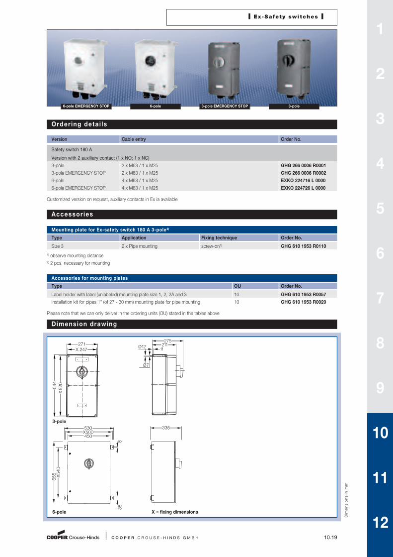
6-pole EMERGENCY STOP 6-pole 3-pole EMERGENCY STOP 3-pole
Order ing detai ls
Version Cable entry Order No.
Safety switch 180 A
Version with 2 auxiliary contact (1 x NO; 1 x NC)
3-pole 2 x M63 / 1 x M25 GHG 266 0006 R0001
3-pole EMERGENCY STOP 2 x M63 / 1 x M25 GHG 266 0006 R0002
6-pole 4 x M63 / 1 x M25 EXKO 224716 L 0000
6-pole EMERGENCY STOP 4 x M63 / 1 x M25 EXKO 224726 L 0000
Customized version on request, auxiliary contacts in Ex ia available
Accessories
Mounting plate for Ex-safety switch 180 A 3-pole2)
Type Application Fixing technique Order No.
Size 3 2 x Pipe mounting screw-on1) GHG 610 1953 R0110
1) observe mounting distance
2) 2 pcs. necessary for mounting
Accessories for mounting plates
Type OU Order No.
Label holder with label (unlabeled) mounting plate size 1, 2, 2A and 3 10 GHG 610 1953 R0057
Installation kit for pipes 1" (of 27 - 30 mm) mounting plate for pipe mounting 10 GHG 610 1953 R0020
Please note that we can only deliver in the ordering units (OU) stated in the tables above
Dim
en
sio
ns i
n m
m
Dimension drawing
3-pole
6-pole X = fixing dimensions
X 247271
X 52
054
4
275211
11 Ø 12
Ø 7
530X500450
8
X540
655
35
335
1
2
3
4
5
6
7
8
9
10
11
12
10.20 C O O P E R C R O U S E - H I N D S G M B H
I Ex-Safety switches I
3-pole 3-pole EMERGENCY STOP 6-pole 6-pole EMERGENCY STOP
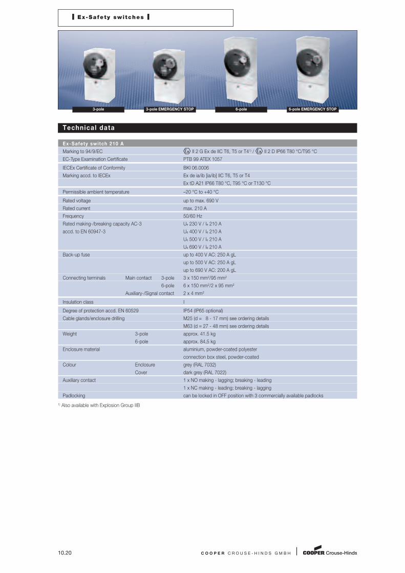
Technical data
Ex-Safety switch 210 A
Marking to 94/9/EC II 2 G Ex de IIC T6, T5 or T41) / II 2 D IP66 T80 °C/T95 °C
EC-Type Examination Certificate PTB 99 ATEX 1057
IECEx Certificate of Conformity BKI 06.0006
Marking accd. to IECEx Ex de ia/ib [ia/ib] IIC T6, T5 or T4
Ex tD A21 IP66 T80 °C, T95 °C or T130 °C
Permissible ambient temperature –20 °C to +40 °C
Rated voltage up to max. 690 V
Rated current max. 210 A
Frequency 50/60 Hz
Rated making-/breaking capacity AC-3 Ue 230 V / Ie 210 A
accd. to EN 60947-3 Ue 400 V / Ie 210 A
Ue 500 V / Ie 210 A
Ue 690 V / Ie 210 A
Back-up fuse up to 400 V AC: 250 A gL
up to 500 V AC: 250 A gL
up to 690 V AC: 200 A gL
Connecting terminals Main contact 3-pole 3 x 150 mm2/95 mm2
6-pole 6 x 150 mm2/2 x 95 mm2
Auxiliary-/Signal contact 2 x 4 mm2
Insulation class I
Degree of protection accd. EN 60529 IP54 (IP65 optional)
Cable glands/enclosure drilling M25 (d = 8 - 17 mm) see ordering details
M63 (d = 27 - 48 mm) see ordering details
Weight 3-pole approx. 41.5 kg
6-pole approx. 84,5 kg
Enclosure material aluminium, powder-coated polyester
connection box steel, powder-coated
Colour Enclosure grey (RAL 7032)
Cover dark grey (RAL 7022)
Auxiliary contact 1 x NO making - lagging; breaking - leading
1 x NC making - leading; breaking - lagging
Padlocking can be locked in OFF position with 3 commercially available padlocks
1) Also available with Explosion Group IIB

I Ex-Safety switches I
C O O P E R C R O U S E - H I N D S G M B H 10.21
6-pole EMERGENCY STOP 6-pole 3-pole EMERGENCY STOP 3-pole
Order ing detai ls
Version Cable entry Order No.
Safety switch 210 A 3-pole
Version with 2 auxiliary contact (1 x NO; 1 x NC)
3-pole 2 x M63 / 1 x M25 EXKO 731713 S0001
3-pole EMERGENCY STOP 2 x M63 / 1 x M25 EXKO 731723 S0001
Safety switch 210 A 6-pole
Version with 2 auxiliary contact (1 x NO; 1 x NC)
6-pole 4 x M63 / 1 x M25 EXKO 731716 S0001
6-pole EMERGENCY STOP 4 x M63 / 1 x M25 EXKO 731726 S0001
Customized version on request, auxiliary contacts in Ex ia available
Dim
en
sio
ns i
n m
m
Dimension drawing
3-pole
6-pole X = fixing dimensions
14
4663
9X
256
326320X 295
329
14
971
156
X 36
5
435430
X 405329
1
2
3
4
5
6
7
8
9
10
11
12

10.22 C O O P E R C R O U S E - H I N D S G M B H
I Ex-Safety switches I
3-pole 3-pole EMERGENCY STOP 6-pole 6-pole EMERGENCY STOP
Technical data
Ex-Safety switch 250 A
Marking to 94/9/EC II 2 G Ex de IIC T6, T5 or T41) / II 2 D IP66 T80 °C/T95 °C
EC-Type Examination Certificate PTB 99 ATEX 1057
IECEx Certificate of Conformity BKI 06.0006
Marking accd. to IECEx Ex de ia/ib [ia/ib] IIC T6, T5 or T4
Ex tD A21 IP66 T80 °C, T95 °C or T130 °C
Permissible ambient temperature –20 °C to +40 °C2)
Rated voltage up to max. 690 V
Rated current max. 250 A
Frequency 50/60 Hz
Rated making-/breaking capacity AC-3 Ue 230 V / Ie 250 A
accd. to EN 60947-3 Ue 400 V / Ie 250 A
Ue 500 V / Ie 250 A
Ue 690 V / Ie 250 A
Back-up fuse up to 400 V AC: 250 A gL
up to 500 V AC: 250 A gL
up to 690 V AC: 200 A gL
Connecting terminals Main contact 3-pole 3 x 150 mm2/95 mm2
6-pole 6 x 150 mm2/2 x 95 mm2
Auxiliary-/Signal contact 2 x 4 mm2
Insulation class I
Degree of protection accd. EN 60529 IP54 (IP65 optional)
Cable glands/enclosure drilling M25 (d = 8 - 17 mm) see ordering details
M63 (d = 27 - 48 mm) see ordering details
Weight 3-pole approx. 41.5 kg
6-pole approx. 84,5 kg
Enclosure material aluminium, powder-coated polyester
connection box steel, powder-coated
Colour Enclosure grey (RAL 7032)
Cover dark grey (RAL 7022)
Auxiliary contact 1 x NO making - lagging; breaking - leading
1 x NC making - leading; breaking - lagging
Padlocking can be locked in OFF position with 3 commercially available padlocks
1) Also available with Explosion Group IIB
2) Other ambient temperatures on request
I Ex-Safety switches I
C O O P E R C R O U S E - H I N D S G M B H 10.23
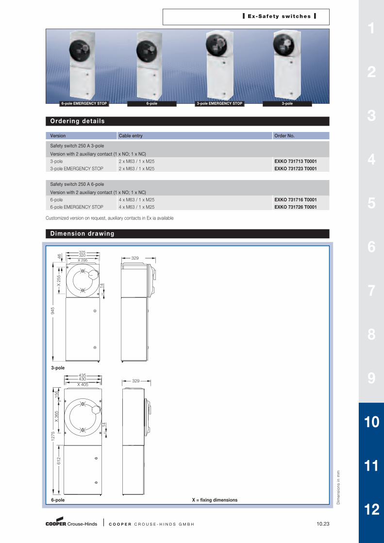
6-pole EMERGENCY STOP 6-pole 3-pole EMERGENCY STOP 3-pole
Order ing detai ls
Version Cable entry Order No.
Safety switch 250 A 3-pole
Version with 2 auxiliary contact (1 x NO; 1 x NC)
3-pole 2 x M63 / 1 x M25 EXKO 731713 T0001
3-pole EMERGENCY STOP 2 x M63 / 1 x M25 EXKO 731723 T0001
Safety switch 250 A 6-pole
Version with 2 auxiliary contact (1 x NO; 1 x NC)
6-pole 4 x M63 / 1 x M25 EXKO 731716 T0001
6-pole EMERGENCY STOP 4 x M63 / 1 x M25 EXKO 731726 T0001
Customized version on request, auxiliary contacts in Ex ia available
Dim
en
sio
ns i
n m
m
Dimension drawing
3-pole
6-pole X = fixing dimensions
329325320
X 295
945
46X
255
1414
1275
156
X 36
561
2
435430 329
X 405
1
2
3
4
5
6
7
8
9
10
11
12

10.24 C O O P E R C R O U S E - H I N D S G M B H
I Ex-Safety switches I
3-pole 3-pole EMERGENCY STOP
Technical data
Ex-Safety switch 400 A
Marking to 94/9/EC II 2 G Ex de IIC T6, T5 or T41) / II 2 D IP66 T80 °C/T95 °C
EC-Type Examination Certificate PTB 99 ATEX 1057
IECEx Certificate of Conformity BKI 06.0006
Marking accd. to IECEx Ex de ia/ib [ia/ib] IIC T6, T5 or T4
Ex tD A21 IP66 T80 °C, T95 °C or T130 °C
Permissible ambient temperature –20 °C to +40 °C2)
Rated voltage up to max. 690 V
Rated current max. 400 A
Frequency 50/60 Hz
Rated making-/breaking capacity AC-3 Ue 230 V / Ie 400 A
accd. to EN 60947-3 Ue 400 V / Ie 400 A
Ue 500 V / Ie 400 A
Ue 690 V / Ie 400 A
Back-up fuse up to 400 V AC: 500 A gL
up to 500 V AC: 500 A gL
up to 690 V AC: 500 A gL
Connecting terminals Main contact 6 x 150 mm2/2 x 95 mm2
Auxiliary-/Signal contact 2 x 4 mm2
Insulation class I
Degree of protection accd. EN 60529 IP54 (IP65 optional)
Cable glands/enclosure drilling M25 (d = 8 - 17 mm) see ordering details
M63 (d = 27 - 48 mm) see ordering details
Weight approx. 64.5 kg
Enclosure material aluminium, powder-coated polyester
connection box steel, powder-coated
Colour Enclosure grey (RAL 7032)
Cover dark grey (RAL 7022)
Auxiliary contact 1 x NO making - lagging; breaking - leading
1 x NC making - leading; breaking - lagging
Padlocking can be locked in OFF position with 3 commercially available padlocks
1) Also available with Explosion Group IIB
2) Other ambient temperatures on request
I Ex-Safety switches I
C O O P E R C R O U S E - H I N D S G M B H 10.25
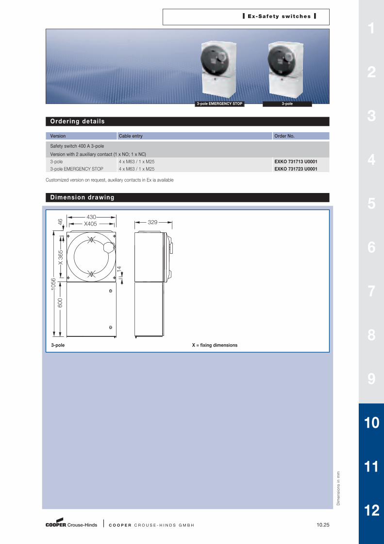
3-pole EMERGENCY STOP 3-pole
Order ing detai ls
Version Cable entry Order No.
Safety switch 400 A 3-pole
Version with 2 auxiliary contact (1 x NO; 1 x NC)
3-pole 4 x M63 / 1 x M25 EXKO 731713 U0001
3-pole EMERGENCY STOP 4 x M63 / 1 x M25 EXKO 731723 U0001
Customized version on request, auxiliary contacts in Ex ia available
Dim
en
sio
ns i
n m
m
Dimension drawing
3-pole X = fixing dimensions
14
1056
X 3
6546
600
430329X405
1
2
3
4
5
6
7
8
9
10
11
12

10.26 C O O P E R C R O U S E - H I N D S G M B H
I Ex-Safety switches I
3-pole
Technical data
Ex-Safety switch 630 A
Marking to 94/9/EC II 2 G Ex de IIC T6, T5 or T41) / II 2 D IP66 T80 °C/T95 °C
EC-Type Examination Certificate PTB 99 ATEX 1057
IECEx Certificate of Conformity BKI 06.0006
Marking accd. to IECEx Ex de ia/ib [ia/ib] IIC T6, T5 or T4
Ex tD A21 IP66 T80 °C, T95 °C or T130 °C
Permissible ambient temperature –20 °C to +40 °C2)
Rated voltage up to max. 690 V
Rated current max. 630 A
Frequency 50/60 Hz
Rated making-/breaking capacity AC-3 Ue 230 V / Ie 630 A
accd. to EN 60947-3 Ue 400 V / Ie 630 A
Ue 500 V / Ie 630 A
Ue 690 V / Ie 630 A
Back-up fuse up to 400 V AC: 800 A gL
up to 500 V AC: 800 A gL
up to 690 V AC: 800 A gL
Connecting terminals Main contact 6 x 240 mm2/2 x 120 mm2
Auxiliary/Signal contact 2 x 4 mm2
Insulation class I
Degree of protection accd. EN 60529 IP54 (IP65 optional)
Cable glands/enclosure drilling M25 (d = 8 - 17 mm) see ordering details
M80 (d = 62 - 68 mm) see ordering details
Weight approx. 245 kg
Enclosure material steel, powder-coated polyester
connection box steel, powder-coated
Colour Enclosure grey (RAL 7032)
Cover dark grey (RAL 7022)
Auxiliary contact 1 x NO making - lagging; breaking - leading
1 x NC making - leading; breaking - lagging
Padlocking can be locked in OFF position with 3 commercially available padlocks
1) Also available with Explosion Group IIB
2) Other ambient temperatures on request
I Ex-Safety switches I
C O O P E R C R O U S E - H I N D S G M B H 10.27
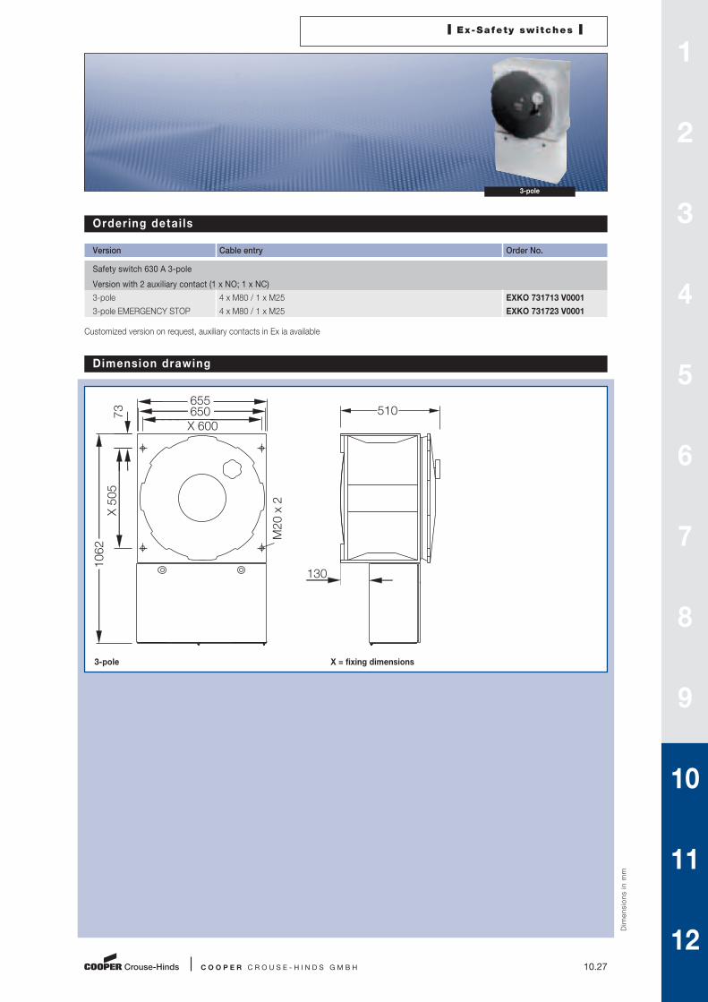
3-pole
Order ing detai ls
Version Cable entry Order No.
Safety switch 630 A 3-pole
Version with 2 auxiliary contact (1 x NO; 1 x NC)
3-pole 4 x M80 / 1 x M25 EXKO 731713 V0001
3-pole EMERGENCY STOP 4 x M80 / 1 x M25 EXKO 731723 V0001
Customized version on request, auxiliary contacts in Ex ia available
Dim
en
sio
ns i
n m
m
Dimension drawing
3-pole X = fixing dimensions
1
2
3
4
5
6
7
8
9
10
11
12
650
M20
x 2
X 600
655510
X 50
510
62
73
130

10.28 C O O P E R C R O U S E - H I N D S G M B H
I Ex-Safety switches I
3-pole, 20 A
Technical data
Ex-Safety switch 20 A for var iable-speed three-phase dr ives
Marking to 94/9/EC II 2 G Ex ed ia IIC T6 / II 2 D Ex tD A21 IP66 T80 °C
EC-Type Examination Certificate PTB 99 ATEX 1161
IECEx Certificate of Conformity BKI 07.0012
Marking accd. to IECEx Ex ed ia IIC T6
Ex tD A21 IP66 T55 °C
Permissible ambient temperature –20 °C to +40 °C1)
Rated voltage up to max. 690 V
Rated current max. 20 A
Frequency 50/60 Hz
Rated making-/breaking capacity AC-3 Ue 230 V / Ie 20 A
accd. to EN 60947-3 Ue 400 V / Ie 20 A
Ue 500 V / Ie 16 A
Ue 690 V / Ie 10 A
Back-up fuse up to 400 V AC: 35 A gL
up to 500 V AC: 35 A gL
up to 690 V AC: 25 A gL
Connecting terminals Main contact 2 x 4 mm2
Auxiliary/Signal contact 2 x 4 mm2
Insulation class I
Degree of protection accd. EN 60529 IP66
Cable glands/enclosure drilling M25 (d = 8 - 17.5 mm) see ordering details
M32 (d = 12 - 21 mm) see ordering details
Option: metal flange with 2 x thread
Weight approx. 1.48 kg
Enclosure material glass-fibre reinforced polyester
Enclosure colour black
Auxiliary contact 1 x NO making - lagging; breaking - leading
1 x NC making - leading; breaking - lagging
Safety interlock for electronics 1 x NO making - lagging; breaking - leading
1) Other ambient temperatures on request
I Ex-Safety switches I
C O O P E R C R O U S E - H I N D S G M B H 10.29
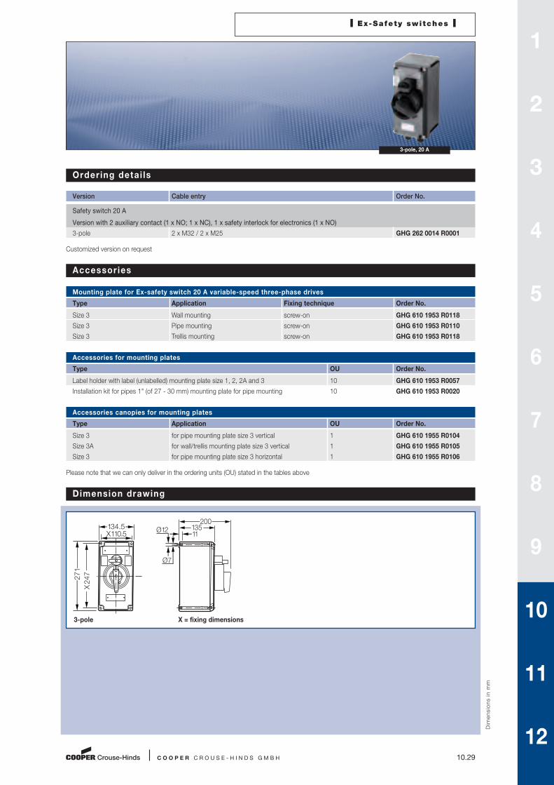
3-pole, 20 A
Order ing detai ls
Version Cable entry Order No.
Safety switch 20 A
Version with 2 auxiliary contact (1 x NO; 1 x NC), 1 x safety interlock for electronics (1 x NO)
3-pole 2 x M32 / 2 x M25 GHG 262 0014 R0001
Customized version on request
Accessories
Mounting plate for Ex-safety switch 20 A variable-speed three-phase drives
Type Application Fixing technique Order No.
Size 3 Wall mounting screw-on GHG 610 1953 R0118
Size 3 Pipe mounting screw-on GHG 610 1953 R0110
Size 3 Trellis mounting screw-on GHG 610 1953 R0118
Accessories for mounting plates
Type OU Order No.
Label holder with label (unlabelled) mounting plate size 1, 2, 2A and 3 10 GHG 610 1953 R0057
Installation kit for pipes 1" (of 27 - 30 mm) mounting plate for pipe mounting 10 GHG 610 1953 R0020
Accessories canopies for mounting plates
Type Application OU Order No.
Size 3 for pipe mounting plate size 3 vertical 1 GHG 610 1955 R0104
Size 3A for wall/trellis mounting plate size 3 vertical 1 GHG 610 1955 R0105
Size 3 for pipe mounting plate size 3 horizontal 1 GHG 610 1955 R0106
Please note that we can only deliver in the ordering units (OU) stated in the tables above
Dim
en
sio
ns i
n m
mDimension drawing
3-pole X = fixing dimensions
X 110.5134.5
X 24
7271
200 135 11 Ø 12
Ø 7
1
2
3
4
5
6
7
8
9
10
11
12

10.30 C O O P E R C R O U S E - H I N D S G M B H
I Ex-Safety switches I
3-pole, 40 A
Technical data
Ex-Safety switch 40 A for var iable-speed three-phase dr ives
Marking to 94/9/EC II 2 G Ex ed ia IIC T6 / II 2 D Ex tD A21 IP66 T80 °C
EC-Type Examination Certificate PTB 99 ATEX 1161
IECEx Certificate of Conformity BKI 07.0012
Marking accd. to IECEx Ex ed ia IIC T6
Ex tD A21 IP66 T53 °C
Permissible ambient temperature –20 °C to +40 °C1)
Rated voltage up to max. 690 V
Rated current max. 40 A
Frequency 50/60 Hz
Rated making-/breaking capacity AC-3 Ue 230 V / Ie 40 A
accd. to EN 60947-3 Ue 400 V / Ie 40 A
Ue 500 V / Ie 40 A
Ue 690 V / Ie 32 A
Back-up fuse up to 400 V AC: 80 A gL
up to 500 V AC: 80 A gL
up to 690 V AC: 63 A gL
Connecting terminals Main contact 2 x 16 mm2
Auxiliary-/Signal contact 2 x 4 mm2
Insulation class I
Degree of protection accd. EN 60529 IP66
Cable glands/enclosure drilling M25 (d = 8 - 17.5 mm) see ordering details
M40 (d = 17 - 28 mm) see ordering details
M50 (d = 22 - 35 mm) see ordering details
Option: metal flange with 2 x thread
Weight approx. 4.3 kg
Enclosure material glass-fibre reinforced polyester
Enclosure colour black
Auxiliary contact 1 x NO making - lagging; breaking - leading
1 x NC making - leading; breaking - lagging
Safety interlock for electronics 1 x NO making - lagging; breaking - leading
Padlocking can be locked in OFF position with 3 commercially available padlocks
1) Other ambient temperatures on request

I Ex-Safety switches I
C O O P E R C R O U S E - H I N D S G M B H 10.31
3-pole, 40 A
Order ing detai ls
Version Cable entry Order No.
Safety switch 40 A 3-pole
Version with 2 auxiliary contacts (1 x NO; 1 x NC), 1 x safety interlock for electronics (1 x NO)
3-pole 2 x M40 / 2 x M25 GHG 263 0053 R0001
Customized version on request, auxiliary contacts in Ex ia available
Dim
en
sio
ns i
n m
m
Dimension drawing
Ex-safety switch 40 A X = fixing dimensions
X 247271
X 24
727
1
200 135 11 Ø 12
Ø 7
Accessories
Mounting plate for Ex-safety switch 125 A/180 A 3-pole
Type Application Fixing technique Order No.
Size 3 2 x Pipe mounting screw-on1) GHG 610 1953 R0110
1) observe mounting distance
Accessories for mounting plates
Type OU Order No.
Label holder with label (unlabelled) mounting plate size 1, 2, 2A and 3 10 GHG 610 1953 R0057
Installation kit for pipes 1" (of 27 - 30 mm) mounting plate for pipe mounting 10 GHG 610 1953 R0020
Please note that we can only deliver in the ordering units (OU) stated in the tables above
1
2
3
4
5
6
7
8
9
10
11
12

10.32 C O O P E R C R O U S E - H I N D S G M B H
I Ex-Safety switches I
3-pole, 80 A
Technical data
Ex-Safety switch 80 A for var iable-speed three-phase dr ives
Marking to 94/9/EC II 2 G Ex de IIC T6 / II 2 D A21 IP66 T80 °C
EC-Type Examination Certificate PTB 00 ATEX 1091
IECEx Certificate of Conformity BKI 07.0010
Marking accd. to IECEx Ex ed ia II T6
Ex tD A21 IP66 T53 °C
Permissible ambient temperature –20 °C to +40 °C
Rated voltage up to max. 690 V
Rated current max. 80 A
Frequency 50/60 Hz
Rated making-/breaking capacity AC-3 Ue 230 V / Ie 80 A
accd. to EN 60947-3 Ue 400 V / Ie 80 A
Ue 500 V / Ie 80 A
Ue 690 V / Ie 63 A
Back-up fuse up to 400 V AC: 160 A gL
up to 500 V AC: 160 A gL
up to 690 V AC: 160 A gL
Connecting terminals Main contact 2 x 25 mm2
Auxiliary-/Signal contact 2 x 4 mm2
Insulation class I
Degree of protection accd. EN 60529 IP66
Cable glands/enclosure drilling M25 (d = 8 - 17.5 mm) see ordering details
M40 (d = 17 - 28 mm) see ordering details
M50 (d = 22 - 35 mm) see ordering details
Option: metal flange with 2 x thread
Weight approx. 7.25 kg
Enclosure material glass-fibre reinforced polyester
Enclosure colour black
Auxiliary contact 1 x NO making - lagging; breaking - leading
1 x NC making - leading; breaking - lagging
Safety interlock for electronics 1 x NO making - lagging; breaking - leading
Padlocking can be locked in OFF position with 3 commercially available padlocks
1) Other ambient temperatures on request

I Ex-Safety switches I
C O O P E R C R O U S E - H I N D S G M B H 10.33
3-pole, 80 A
Order ing detai ls
Version Cable entry Order No.
Safety switch 80 A 3-pole
Version with 2 auxiliary contacts (1 x NO; 1 x NC), 1 x safety interlock for electronics (1 x NO)
3-pole 2 x M50 / 2 x M25 GHG 264 0024 R0001
Customized version on request, auxiliary contacts in Ex ia available
Dim
en
sio
ns i
n m
m
Dimension drawing
Ex-safety switch 80 A X = fixing dimensions
X 247271
X 24
727
1
27511 Ø 12
Ø 7
Accessories
Mounting plate for Ex-safety switch 80 A variable-speed three-phase drives
Type Application Fixing technique Order No.
Size 3 2 x Pipe mounting screw-on1) GHG 610 1953 R0110
1) observe mounting distance
Accessories for mounting plates
Type OU Order No.
Label holder with label (unlabelled) mounting plate size 1, 2, 2A and 3 10 GHG 610 1953 R0057
Installation kit for pipes 1" (of 27 - 30 mm) mounting plate for pipe mounting 10 GHG 610 1953 R0020
Please note that we can only deliver in the ordering units (OU) stated in the tables above
1
2
3
4
5
6
7
8
9
10
11
12