Embed Size (px)
Citation preview
James J. Zakrajsek, David B. McKissock, Jeffrey M. Woytach, June F. Zakrajsek,Fred B. Oswald, Kelly J. McEntire, Gerald M. Hill, Phillip Abel, Dennis J. Eichenberg,and Thomas W. GoodnightGlenn Research Center, Cleveland, Ohio
Exploration Rover Concepts andDevelopment Challenges
NASA/TM—2005-213555
March 2005
AIAA–2005–2525
https://ntrs.nasa.gov/search.jsp?R=20050175879 2018-06-16T05:53:23+00:00Z
The NASA STI Program Office . . . in Profile
Since its founding, NASA has been dedicated tothe advancement of aeronautics and spacescience. The NASA Scientific and TechnicalInformation (STI) Program Office plays a key partin helping NASA maintain this important role.
The NASA STI Program Office is operated byLangley Research Center, the Lead Center forNASA’s scientific and technical information. TheNASA STI Program Office provides access to theNASA STI Database, the largest collection ofaeronautical and space science STI in the world.The Program Office is also NASA’s institutionalmechanism for disseminating the results of itsresearch and development activities. These resultsare published by NASA in the NASA STI ReportSeries, which includes the following report types:
• TECHNICAL PUBLICATION. Reports ofcompleted research or a major significantphase of research that present the results ofNASA programs and include extensive dataor theoretical analysis. Includes compilationsof significant scientific and technical data andinformation deemed to be of continuingreference value. NASA’s counterpart of peer-reviewed formal professional papers buthas less stringent limitations on manuscriptlength and extent of graphic presentations.
• TECHNICAL MEMORANDUM. Scientificand technical findings that are preliminary orof specialized interest, e.g., quick releasereports, working papers, and bibliographiesthat contain minimal annotation. Does notcontain extensive analysis.
• CONTRACTOR REPORT. Scientific andtechnical findings by NASA-sponsoredcontractors and grantees.
• CONFERENCE PUBLICATION. Collectedpapers from scientific and technicalconferences, symposia, seminars, or othermeetings sponsored or cosponsored byNASA.
• SPECIAL PUBLICATION. Scientific,technical, or historical information fromNASA programs, projects, and missions,often concerned with subjects havingsubstantial public interest.
• TECHNICAL TRANSLATION. English-language translations of foreign scientificand technical material pertinent to NASA’smission.
Specialized services that complement the STIProgram Office’s diverse offerings includecreating custom thesauri, building customizeddatabases, organizing and publishing researchresults . . . even providing videos.
For more information about the NASA STIProgram Office, see the following:
• Access the NASA STI Program Home Pageat http://www.sti.nasa.gov
• E-mail your question via the Internet [email protected]
• Fax your question to the NASA AccessHelp Desk at 301–621–0134
• Telephone the NASA Access Help Desk at301–621–0390
• Write to: NASA Access Help Desk NASA Center for AeroSpace Information 7121 Standard Drive Hanover, MD 21076
James J. Zakrajsek, David B. McKissock, Jeffrey M. Woytach, June F. Zakrajsek,Fred B. Oswald, Kelly J. McEntire, Gerald M. Hill, Phillip Abel, Dennis J. Eichenberg,and Thomas W. GoodnightGlenn Research Center, Cleveland, Ohio
Exploration Rover Concepts andDevelopment Challenges
NASA/TM—2005-213555
March 2005
National Aeronautics andSpace Administration
Glenn Research Center
Prepared for theFirst Space Exploration Conference: Continuing the Voyage of Discoverysponsored by the American Institute of Aeronautics and AstronauticsOrlando, Florida, January 30–February 1, 2005
AIAA–2005–2525
Acknowledgments
The authors wish to thank Mr. Tom Kerslake, NASA Glenn Research Center, for consultations regarding prior roverconcepts and for his insightful review comments, and Mr. Paul Solano, NASA Glenn Research Center, for his work
in developing the concepts depicted in figures 17, 18, and 19. The authors would also like to thank Dr. R. AllenWilkinson for consultations on the Lunar environment section, and Dr. Timothy Krantz for final review of the
paper prior to submission.
Available from
NASA Center for Aerospace Information7121 Standard DriveHanover, MD 21076
National Technical Information Service5285 Port Royal RoadSpringfield, VA 22100
Trade names or manufacturers’ names are used in this report foridentification only. This usage does not constitute an officialendorsement, either expressed or implied, by the National
Aeronautics and Space Administration.
Available electronically at http://gltrs.grc.nasa.gov
NASA/TM—2005-213555 1
Exploration Rover Concepts and Development Challenges
James J. Zakrajsek, David B. McKissock, Jeffrey M. Woytach, June F. Zakrajsek, Fred B. Oswald, Kelly J. McEntire, Gerald M. Hill, Phillip Abel,
Dennis J. Eichenberg, and Thomas W. Goodnight National Aeronautics and Space Administration
Glenn Research Center, Cleveland, Ohio 44135
Abstract
This paper presents an overview of exploration rover concepts and the various development challenges associated with each as they are applied to exploration objectives and requirements for missions on the Moon and Mars. A variety of concepts for surface exploration vehicles have been proposed since the initial development of the Apollo-era lunar rover. These concepts range from small autonomous rovers to large pressurized crewed rovers capable of carrying several astronauts hundreds of kilometers and for weeks at a time. This paper provides a brief description of the rover concepts, along with a comparison of their relative benefits and limitations. In addition, this paper outlines, and investigates a number of critical development challenges that surface exploration vehicles must address in order to successfully meet the exploration mission vision.
Major development challenges investigated in this paper include: mission and environmental challenges, design challenges, and production and delivery challenges. Mission and environmental challenges include effects of terrain, extreme temperature differentials, dust issues, and radiation protection. Mission profiles envisioned for Lunar and Mars surface exploration is also investigated. Design methods are discussed that focus on optimum methods for developing highly reliable, long-life and efficient systems. Design modularity and its importance to inexpensive and efficient tailoring for specific missions is also investigated. Notional teaming strategies are discussed, including benefits of tapping into traditionally non-space oriented manufacturers. In addition, challenges associated with delivering a surface exploration system is explored and discussed.
Based on all the information presented, modularity will be the single most important factor in the development of a truly viable surface mobility vehicle. To meet mission, reliability, and affordability requirements, surface exploration vehicles, especially pressurized rovers, will need to be modularly designed and deployed across all projected Moon and Mars exploration missions. The modular concept should start as unmanned teleoperated rovers, and grow into a variety of manned vehicles by upgrading and adding additional modules.
I. Introduction
On January 14, 2004, the President of the United States announced a bold new Vision for Space Exploration.
This new vision calls for a return to the moon in a series of missions that start with robotic and short duration human missions, and expands to long duration moon missions. These lunar missions will prepare us for the next steps, which calls for the eventual human exploration of Mars and beyond. One very important element of the overall program is the means to safely and efficiently explore the planetary surface once we get there. As such, surface mobility will be the key component for accomplishing the primary objective of this new vision: exploration of new worlds for the benefit of humankind.
Surface mobility will be crucial for accomplishing many tasks ranging from site preparation, construction and local transportation to prolonged exploration sorties many kilometers from the primary base. Surface mobility systems are needed to assist the astronauts in the day to day operation and maintenance of the base and all related infrastructure. The astronauts will need mobility systems to transport personnel and supplies to and from the landing sites, storage facilities, and habitat modules. They may also need mobility systems capable of moving and hauling the soil for landing and habitat site preparation, radiation shielding, and burying biological and possible radioactive wastes. Whether it is short day sorties with unpressurized rovers, or month long sorties in large pressurized vehicles, surface mobility systems are the key element in extending exploration activities well beyond the immediate confines
NASA/TM—2005-213555 2
of the base and landing area. Mars has a surface area of approximately 144 million square kilometers, about the same area as all the combined land mass of earth. Clearly the astronauts will need to be mobile to explore this vast new world.
Eight successful rovers have been deployed on the Moon and Mars over the last 35 years. These include crewed vehicles as well as teleoperated (remotely piloted), and autonomous robots. The United States Lunar Roving Vehicle used on the Apollo missions and the Soviet Union’s two Lunokhod lunar rovers explored the Moon. The Mars Pathfinder rover performed beyond expectations, and the Mars Excursion Rovers Spirit and Opportunity continue to perform well. The designs of these rovers are discussed below to illustrate design solutions successfully employed for surface explorations of the Moon and Mars.
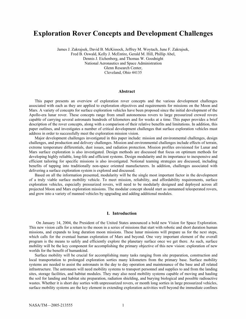
A. Apollo Lunar Roving Vehicle The Lunar Roving Vehicle (LRV), pictured in figure 1, was
an electric vehicle designed to traverse the lunar surface, allowing the Apollo astronauts to extend the range of their surface extravehicular activities. Three LRVs were driven on the Moon on Apollo 15, 16, and 17. Each rover was used on three traverses, one per day over the three day course of each mission. The longest traverse was 20.1 km and the greatest range from the Lunar Module (LM) was 7.6 km, both on the Apollo 17 mission.1
The LRV had a mass of 210 kg and was designed to hold a payload of an additional 490 kg on the lunar surface. The frame was 3.1 meters long with a wheelbase of 2.3 meters. The frame was made of aluminum alloy 2219 tubing welded assemblies and consisted of a 3 part chassis which was hinged in the center so it could be folded up and hung in the Lunar Module quad 1 bay. The wheels consisted of a spun aluminum hub and an 81.8 cm diameter, 23 cm wide tire made of zinc coated woven steel strands. Titanium chevrons covered 50 percent of the contact area to provide traction. Each wheel had its own electric drive, a DC series wound 190 w motor capable of 10,000 rpm, attached to the wheel via an 80:1 harmonic drive, and a mechanical brake unit. Power was provided by two 36-volt silver-zinc potassium hydroxide nonrechargeable batteries with a capacity of 121 amp-hr.1
Apollo 15 astronauts Dave Scott and Jim Irwin were the first to use the LRV. During three EVAs, the astronauts drove the LRV 28 km in the Hadley Rille area. The LRV allowed the Apollo 15 crew to collect 77 kg of lunar samples, nearly double that of the Apollo 14 mission. The crew termed the LRV a “remarkable machine.” On Apollo 16, astronauts explored the lunar surface near Descartes crater using the LRV. Astronaut John Young reported that the area was more rugged than expected. Without the LRV, he estimated that they would have been unable to accomplish more than five percent of their exploration. Lunar samples totaling 97 kg were collected. On Apollo 17, the astronauts achieved a new “lunar speed record” of 17 km/hr driving down hill on their return trip to the lunar module. Astronaut Harrison Schmitt said, “....the Lunar Rover proved to be the reliable, safe and flexible lunar exploration vehicle we expected it to be. Without it, the major scientific discoveries of Apollo 15, 16, and 17 would not have been possible; and our current understanding of lunar evolution would not have been possible.”2
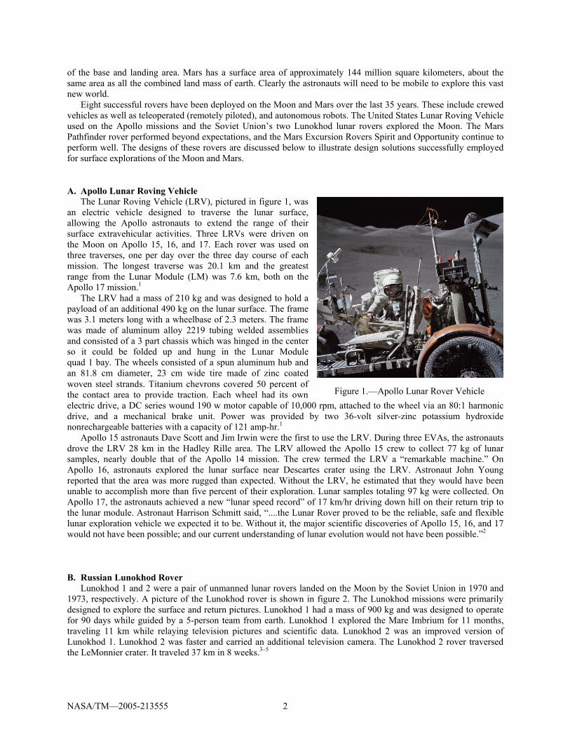
B. Russian Lunokhod Rover Lunokhod 1 and 2 were a pair of unmanned lunar rovers landed on the Moon by the Soviet Union in 1970 and
1973, respectively. A picture of the Lunokhod rover is shown in figure 2. The Lunokhod missions were primarily designed to explore the surface and return pictures. Lunokhod 1 had a mass of 900 kg and was designed to operate for 90 days while guided by a 5-person team from earth. Lunokhod 1 explored the Mare Imbrium for 11 months, traveling 11 km while relaying television pictures and scientific data. Lunokhod 2 was an improved version of Lunokhod 1. Lunokhod 2 was faster and carried an additional television camera. The Lunokhod 2 rover traversed the LeMonnier crater. It traveled 37 km in 8 weeks.3–5
Figure 1.—Apollo Lunar Rover Vehicle
NASA/TM—2005-213555 3
Lunokhod 2 stood 135 cm high, 170 cm long and 160 cm wide, with a mass of 840 kg. The 8 wheels each had an independent suspension, motor and brake. The rover had two speeds, ~1 km/hr and ~2 km/hr. Using cameras mounted on the vehicle, a five-man team of controllers on Earth sent driving commands to the rover in real time. Power was supplied by batteries charged by a solar panel on the inside of a round hinged lid which covered the instrument bay. A Polonium-210 isotopic heat source was used to keep the rover warm during the lunar nights.3
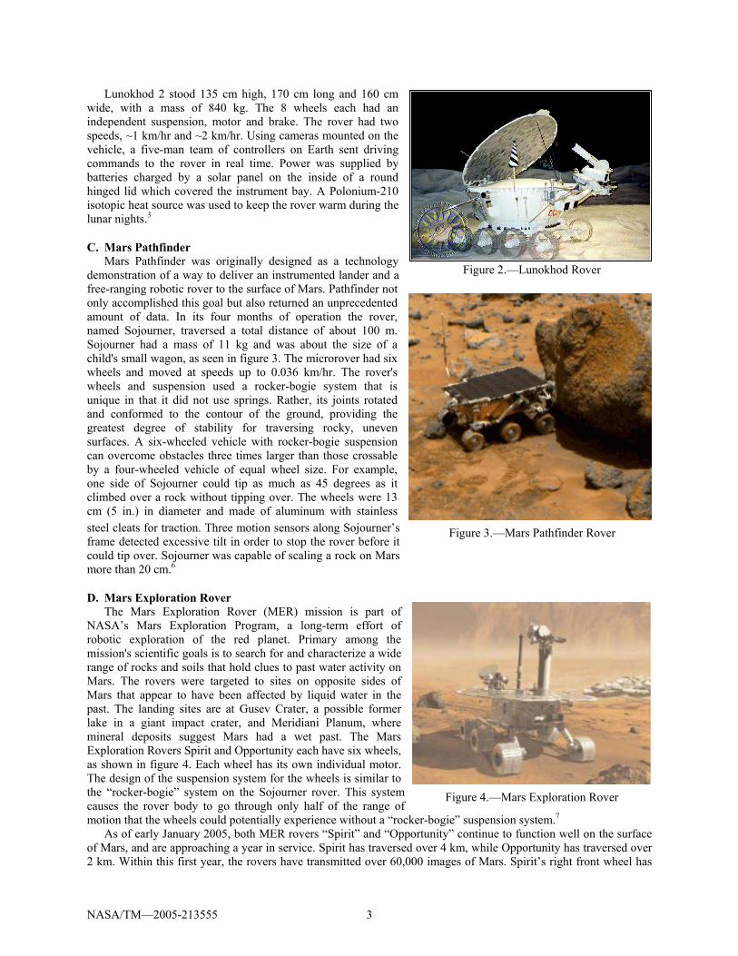
C. Mars Pathfinder Mars Pathfinder was originally designed as a technology
demonstration of a way to deliver an instrumented lander and a free-ranging robotic rover to the surface of Mars. Pathfinder not only accomplished this goal but also returned an unprecedented amount of data. In its four months of operation the rover, named Sojourner, traversed a total distance of about 100 m. Sojourner had a mass of 11 kg and was about the size of a child's small wagon, as seen in figure 3. The microrover had six wheels and moved at speeds up to 0.036 km/hr. The rover's wheels and suspension used a rocker-bogie system that is unique in that it did not use springs. Rather, its joints rotated and conformed to the contour of the ground, providing the greatest degree of stability for traversing rocky, uneven surfaces. A six-wheeled vehicle with rocker-bogie suspension can overcome obstacles three times larger than those crossable by a four-wheeled vehicle of equal wheel size. For example, one side of Sojourner could tip as much as 45 degrees as it climbed over a rock without tipping over. The wheels were 13 cm (5 in.) in diameter and made of aluminum with stainless steel cleats for traction. Three motion sensors along Sojourner’s frame detected excessive tilt in order to stop the rover before it could tip over. Sojourner was capable of scaling a rock on Mars more than 20 cm.6
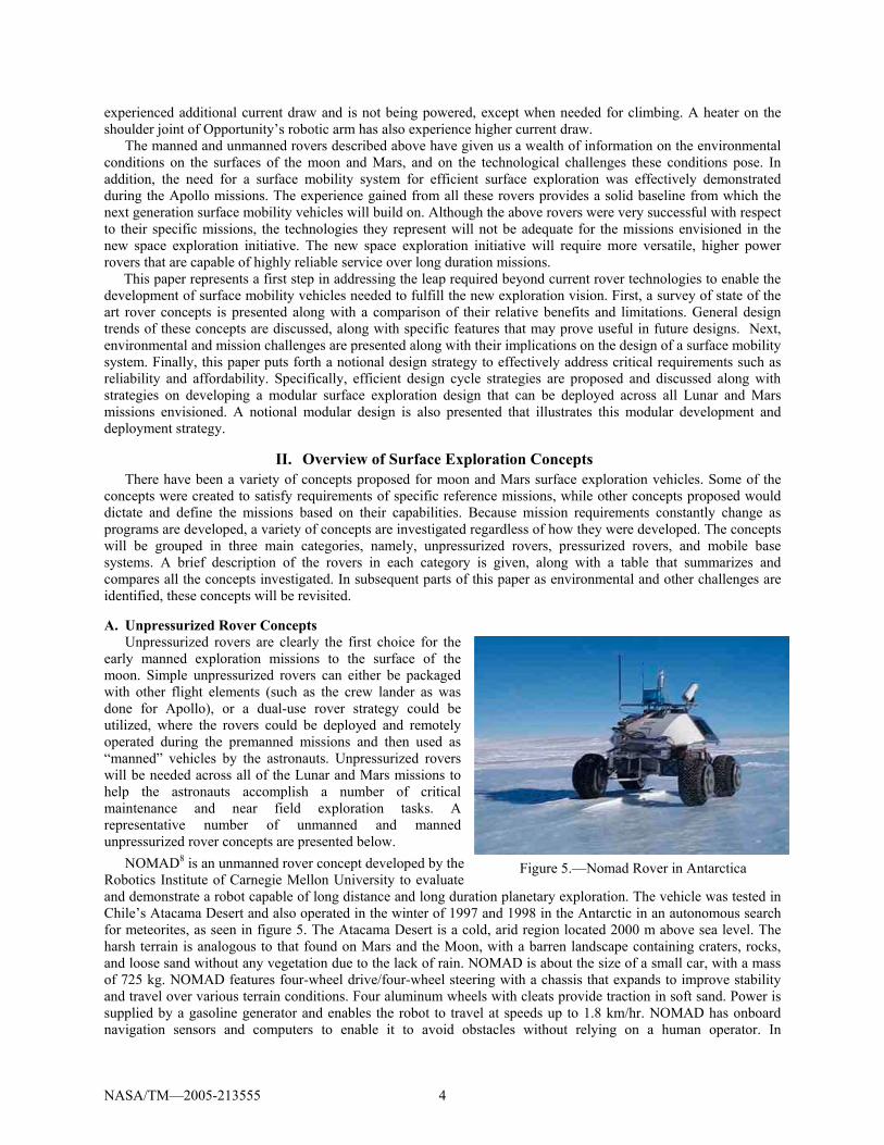
D. Mars Exploration Rover The Mars Exploration Rover (MER) mission is part of
NASA’s Mars Exploration Program, a long-term effort of robotic exploration of the red planet. Primary among the mission's scientific goals is to search for and characterize a wide range of rocks and soils that hold clues to past water activity on Mars. The rovers were targeted to sites on opposite sides of Mars that appear to have been affected by liquid water in the past. The landing sites are at Gusev Crater, a possible former lake in a giant impact crater, and Meridiani Planum, where mineral deposits suggest Mars had a wet past. The Mars Exploration Rovers Spirit and Opportunity each have six wheels, as shown in figure 4. Each wheel has its own individual motor. The design of the suspension system for the wheels is similar to the “rocker-bogie” system on the Sojourner rover. This system causes the rover body to go through only half of the range of motion that the wheels could potentially experience without a “rocker-bogie” suspension system.7
As of early January 2005, both MER rovers “Spirit” and “Opportunity” continue to function well on the surface of Mars, and are approaching a year in service. Spirit has traversed over 4 km, while Opportunity has traversed over 2 km. Within this first year, the rovers have transmitted over 60,000 images of Mars. Spirit’s right front wheel has
Figure 2.—Lunokhod Rover
Figure 3.—Mars Pathfinder Rover
Figure 4.—Mars Exploration Rover
NASA/TM—2005-213555 4
experienced additional current draw and is not being powered, except when needed for climbing. A heater on the shoulder joint of Opportunity’s robotic arm has also experience higher current draw.
The manned and unmanned rovers described above have given us a wealth of information on the environmental conditions on the surfaces of the moon and Mars, and on the technological challenges these conditions pose. In addition, the need for a surface mobility system for efficient surface exploration was effectively demonstrated during the Apollo missions. The experience gained from all these rovers provides a solid baseline from which the next generation surface mobility vehicles will build on. Although the above rovers were very successful with respect to their specific missions, the technologies they represent will not be adequate for the missions envisioned in the new space exploration initiative. The new space exploration initiative will require more versatile, higher power rovers that are capable of highly reliable service over long duration missions.
This paper represents a first step in addressing the leap required beyond current rover technologies to enable the development of surface mobility vehicles needed to fulfill the new exploration vision. First, a survey of state of the art rover concepts is presented along with a comparison of their relative benefits and limitations. General design trends of these concepts are discussed, along with specific features that may prove useful in future designs. Next, environmental and mission challenges are presented along with their implications on the design of a surface mobility system. Finally, this paper puts forth a notional design strategy to effectively address critical requirements such as reliability and affordability. Specifically, efficient design cycle strategies are proposed and discussed along with strategies on developing a modular surface exploration design that can be deployed across all Lunar and Mars missions envisioned. A notional modular design is also presented that illustrates this modular development and deployment strategy.
II. Overview of Surface Exploration Concepts There have been a variety of concepts proposed for moon and Mars surface exploration vehicles. Some of the
concepts were created to satisfy requirements of specific reference missions, while other concepts proposed would dictate and define the missions based on their capabilities. Because mission requirements constantly change as programs are developed, a variety of concepts are investigated regardless of how they were developed. The concepts will be grouped in three main categories, namely, unpressurized rovers, pressurized rovers, and mobile base systems. A brief description of the rovers in each category is given, along with a table that summarizes and compares all the concepts investigated. In subsequent parts of this paper as environmental and other challenges are identified, these concepts will be revisited.
A. Unpressurized Rover Concepts Unpressurized rovers are clearly the first choice for the
early manned exploration missions to the surface of the moon. Simple unpressurized rovers can either be packaged with other flight elements (such as the crew lander as was done for Apollo), or a dual-use rover strategy could be utilized, where the rovers could be deployed and remotely operated during the premanned missions and then used as “manned” vehicles by the astronauts. Unpressurized rovers will be needed across all of the Lunar and Mars missions to help the astronauts accomplish a number of critical maintenance and near field exploration tasks. A representative number of unmanned and manned unpressurized rover concepts are presented below.
NOMAD8 is an unmanned rover concept developed by the Robotics Institute of Carnegie Mellon University to evaluate and demonstrate a robot capable of long distance and long duration planetary exploration. The vehicle was tested in Chile’s Atacama Desert and also operated in the winter of 1997 and 1998 in the Antarctic in an autonomous search for meteorites, as seen in figure 5. The Atacama Desert is a cold, arid region located 2000 m above sea level. The harsh terrain is analogous to that found on Mars and the Moon, with a barren landscape containing craters, rocks, and loose sand without any vegetation due to the lack of rain. NOMAD is about the size of a small car, with a mass of 725 kg. NOMAD features four-wheel drive/four-wheel steering with a chassis that expands to improve stability and travel over various terrain conditions. Four aluminum wheels with cleats provide traction in soft sand. Power is supplied by a gasoline generator and enables the robot to travel at speeds up to 1.8 km/hr. NOMAD has onboard navigation sensors and computers to enable it to avoid obstacles without relying on a human operator. In
Figure 5.—Nomad Rover in Antarctica
NASA/TM—2005-213555 5
its 138 mile trek through the Atacama Desert, NOMAD made the longest teleoperated cross-country traverse ever accomplished by a robot.
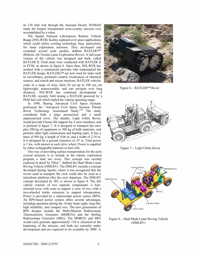
The Sandia National Laboratories Robotic Vehicle Range (SNL/RVR) facility explored civil space applications which could utilize existing technology base, particularly for lunar exploration missions. They developed and evaluated several scale models, dubbed RATLER™9 (Robotic All Terrain Lunar Exploration Rover). A full-scale version of the vehicle was designed and built, called RATLER II. Field trials were conducted with RATLER II in FY94, as shown in figure 6. Since then, SNL/RVR has worked with a commercial provider who trademarked the RATLER design. RATLERs™ are now used for tasks such as surveillance, perimeter control, localization of chemical sources, and search and rescue missions. RATLER vehicles come in a range of sizes, from 20 cm up to 100 cm; are lightweight, maneuverable; and can navigate over long distances. SNL/RVR has continued development of RATLER, recently field testing a RATLER powered by a PEM fuel cell which tripled the vehicle operating range.
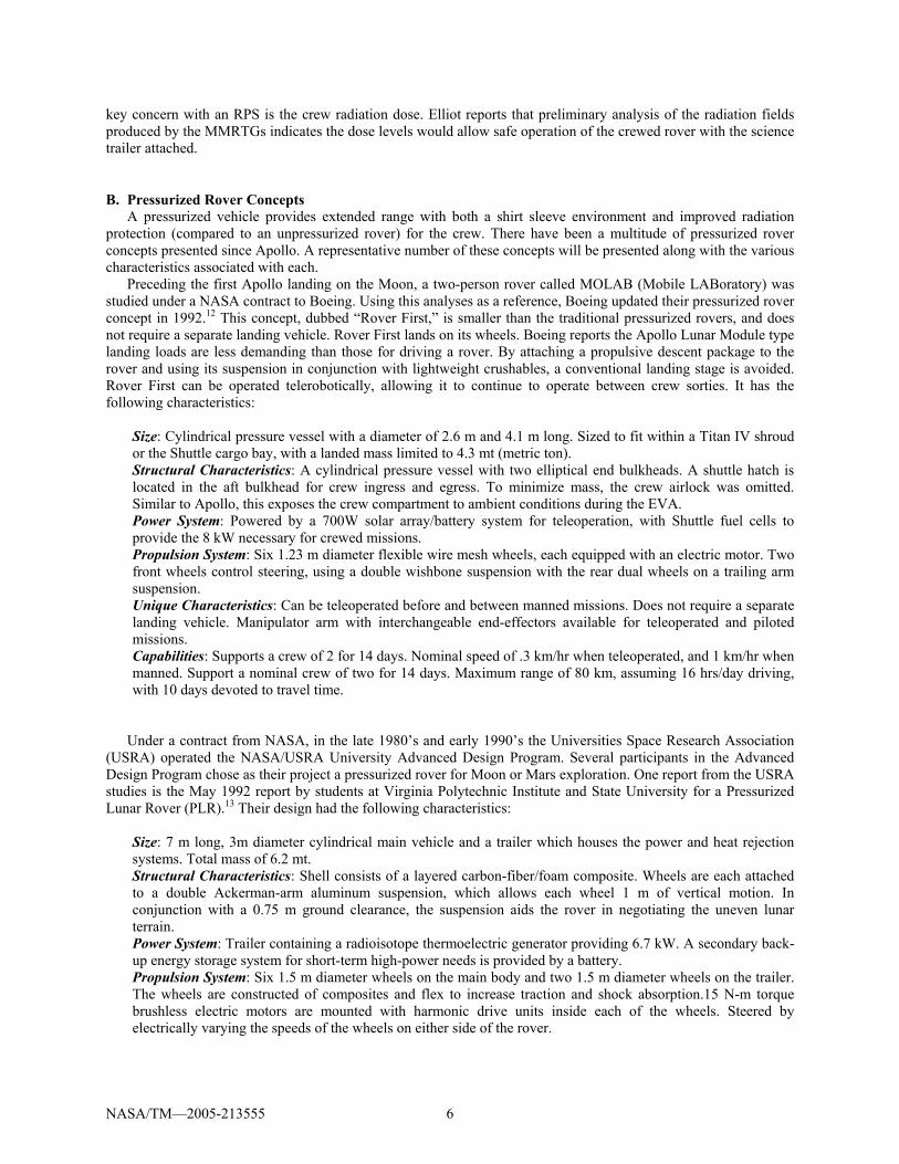
In 1990, Boeing Advanced Civil Space Systems performed the “Advanced Civil Space Systems Piloted Rover Technology Assessment Study.”10 The study considered both a large pressurized and a small unpressurized rover. The smaller, Light Utility Rover, would provide 8 hours life support for 2 crew members, and is pictured in figure 7. It is designed to transport the crew plus 200 kg of equipment or 300 kg of bulk materials, and perform other light construction and hauling tasks. It has a mass of 984 kg, a length of 4.06 m, and a width of 2.34 m. It is designed for a ground clearance of .47 m. Total power is 1 kw, with motors in each drive wheel. Power is supplied by either rechargeable batteries or fuel cells.
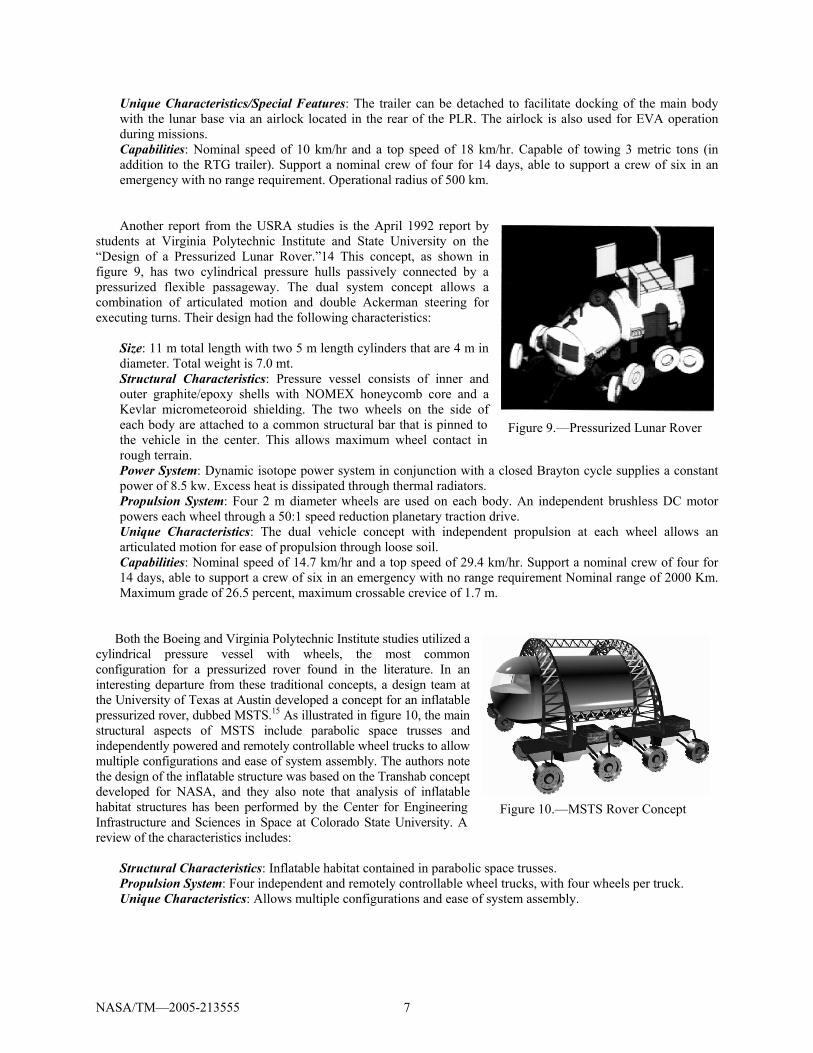
One way of providing surface transportation for the early crewed missions is to include in the robotic exploration program a dual use rover. This concept was recently explored in detail by Elliot,11 dubbed the Dual Mode Lunar Roving Vehicle (DMLRV). The DMLRV extends a concept developed during Apollo, where it was recognized that the rovers used to transport the crew could also be used as a telerobotic platform after the crew departure. The DMLRV concept developed by JPL is shown in figure 8. The full vehicle consists of two separate components: a four-wheeled rover with seats to support a crew of two, with a two-wheeled trailer extension to support teleoperation. Power is provided by a radioisotope power source (RPS). An RPS-based power system offers several advantages, including operation during the 14-day lunar night, long-life, high reliability, and compact size. The next generations of RPS designs include the Multi-Mission Radioisotope Thermoelectric Generator (MMRTG) and the Stirling Radioisotope Generator (SRG). The MMRTG and SRG would each generate approximately 110 w electrical at the beginning of the mission, and both are currently under development and are expected to be available by 2009. A
Figure 6.—RATLER™ Rover
Figure 7.—Light Utility Rover
Figure 8.—Dual Mode Lunar Roving Vehicle (DMLRV)
NASA/TM—2005-213555 6
key concern with an RPS is the crew radiation dose. Elliot reports that preliminary analysis of the radiation fields produced by the MMRTGs indicates the dose levels would allow safe operation of the crewed rover with the science trailer attached.
B. Pressurized Rover Concepts A pressurized vehicle provides extended range with both a shirt sleeve environment and improved radiation
protection (compared to an unpressurized rover) for the crew. There have been a multitude of pressurized rover concepts presented since Apollo. A representative number of these concepts will be presented along with the various characteristics associated with each.
Preceding the first Apollo landing on the Moon, a two-person rover called MOLAB (Mobile LABoratory) was studied under a NASA contract to Boeing. Using this analyses as a reference, Boeing updated their pressurized rover concept in 1992.12 This concept, dubbed “Rover First,” is smaller than the traditional pressurized rovers, and does not require a separate landing vehicle. Rover First lands on its wheels. Boeing reports the Apollo Lunar Module type landing loads are less demanding than those for driving a rover. By attaching a propulsive descent package to the rover and using its suspension in conjunction with lightweight crushables, a conventional landing stage is avoided. Rover First can be operated telerobotically, allowing it to continue to operate between crew sorties. It has the following characteristics:
Size: Cylindrical pressure vessel with a diameter of 2.6 m and 4.1 m long. Sized to fit within a Titan IV shroud or the Shuttle cargo bay, with a landed mass limited to 4.3 mt (metric ton). Structural Characteristics: A cylindrical pressure vessel with two elliptical end bulkheads. A shuttle hatch is located in the aft bulkhead for crew ingress and egress. To minimize mass, the crew airlock was omitted. Similar to Apollo, this exposes the crew compartment to ambient conditions during the EVA. Power System: Powered by a 700W solar array/battery system for teleoperation, with Shuttle fuel cells to provide the 8 kW necessary for crewed missions. Propulsion System: Six 1.23 m diameter flexible wire mesh wheels, each equipped with an electric motor. Two front wheels control steering, using a double wishbone suspension with the rear dual wheels on a trailing arm suspension. Unique Characteristics: Can be teleoperated before and between manned missions. Does not require a separate landing vehicle. Manipulator arm with interchangeable end-effectors available for teleoperated and piloted missions. Capabilities: Supports a crew of 2 for 14 days. Nominal speed of .3 km/hr when teleoperated, and 1 km/hr when manned. Support a nominal crew of two for 14 days. Maximum range of 80 km, assuming 16 hrs/day driving, with 10 days devoted to travel time.
Under a contract from NASA, in the late 1980’s and early 1990’s the Universities Space Research Association (USRA) operated the NASA/USRA University Advanced Design Program. Several participants in the Advanced Design Program chose as their project a pressurized rover for Moon or Mars exploration. One report from the USRA studies is the May 1992 report by students at Virginia Polytechnic Institute and State University for a Pressurized Lunar Rover (PLR).13 Their design had the following characteristics:
Size: 7 m long, 3m diameter cylindrical main vehicle and a trailer which houses the power and heat rejection systems. Total mass of 6.2 mt. Structural Characteristics: Shell consists of a layered carbon-fiber/foam composite. Wheels are each attached to a double Ackerman-arm aluminum suspension, which allows each wheel 1 m of vertical motion. In conjunction with a 0.75 m ground clearance, the suspension aids the rover in negotiating the uneven lunar terrain. Power System: Trailer containing a radioisotope thermoelectric generator providing 6.7 kW. A secondary back-up energy storage system for short-term high-power needs is provided by a battery. Propulsion System: Six 1.5 m diameter wheels on the main body and two 1.5 m diameter wheels on the trailer. The wheels are constructed of composites and flex to increase traction and shock absorption.15 N-m torque brushless electric motors are mounted with harmonic drive units inside each of the wheels. Steered by electrically varying the speeds of the wheels on either side of the rover.
NASA/TM—2005-213555 7
Unique Characteristics/Special Features: The trailer can be detached to facilitate docking of the main body with the lunar base via an airlock located in the rear of the PLR. The airlock is also used for EVA operation during missions. Capabilities: Nominal speed of 10 km/hr and a top speed of 18 km/hr. Capable of towing 3 metric tons (in addition to the RTG trailer). Support a nominal crew of four for 14 days, able to support a crew of six in an emergency with no range requirement. Operational radius of 500 km. Another report from the USRA studies is the April 1992 report by
students at Virginia Polytechnic Institute and State University on the “Design of a Pressurized Lunar Rover.”14 This concept, as shown in figure 9, has two cylindrical pressure hulls passively connected by a pressurized flexible passageway. The dual system concept allows a combination of articulated motion and double Ackerman steering for executing turns. Their design had the following characteristics:
Size: 11 m total length with two 5 m length cylinders that are 4 m in diameter. Total weight is 7.0 mt. Structural Characteristics: Pressure vessel consists of inner and outer graphite/epoxy shells with NOMEX honeycomb core and a Kevlar micrometeoroid shielding. The two wheels on the side of each body are attached to a common structural bar that is pinned to the vehicle in the center. This allows maximum wheel contact in rough terrain. Power System: Dynamic isotope power system in conjunction with a closed Brayton cycle supplies a constant power of 8.5 kw. Excess heat is dissipated through thermal radiators. Propulsion System: Four 2 m diameter wheels are used on each body. An independent brushless DC motor powers each wheel through a 50:1 speed reduction planetary traction drive. Unique Characteristics: The dual vehicle concept with independent propulsion at each wheel allows an articulated motion for ease of propulsion through loose soil. Capabilities: Nominal speed of 14.7 km/hr and a top speed of 29.4 km/hr. Support a nominal crew of four for 14 days, able to support a crew of six in an emergency with no range requirement Nominal range of 2000 Km. Maximum grade of 26.5 percent, maximum crossable crevice of 1.7 m.
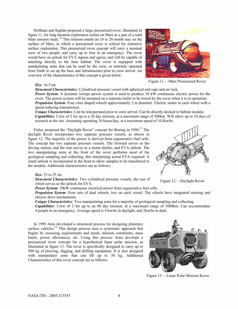
Both the Boeing and Virginia Polytechnic Institute studies utilized a cylindrical pressure vessel with wheels, the most common configuration for a pressurized rover found in the literature. In an interesting departure from these traditional concepts, a design team at the University of Texas at Austin developed a concept for an inflatable pressurized rover, dubbed MSTS.15 As illustrated in figure 10, the main structural aspects of MSTS include parabolic space trusses and independently powered and remotely controllable wheel trucks to allow multiple configurations and ease of system assembly. The authors note the design of the inflatable structure was based on the Transhab concept developed for NASA, and they also note that analysis of inflatable habitat structures has been performed by the Center for Engineering Infrastructure and Sciences in Space at Colorado State University. A review of the characteristics includes:
Structural Characteristics: Inflatable habitat contained in parabolic space trusses. Propulsion System: Four independent and remotely controllable wheel trucks, with four wheels per truck. Unique Characteristics: Allows multiple configurations and ease of system assembly.
Figure 9.—Pressurized Lunar Rover
Figure 10.—MSTS Rover Concept
NASA/TM—2005-213555 8
Hoffman and Kaplan proposed a large pressurized rover, illustrated in figure 11, for long duration exploration sorties on Mars as a part of a total Mars mission study.16 This mission entails an 18 to 20 month stay on the surface of Mars, in which a pressurized rover is critical for extensive surface exploration. This pressurized rover concept will carry a nominal crew of two people, and carry up to four in an emergency. The rover would have an airlock for EVA ingress and egress, and will be capable of attaching directly to the base habitat. The rover is equipped with manipulating arms that can be used by the crew, or remotely operated from Earth to set up the base and infrastructure prior to crew arrival. An overview of the characteristics of this concept is given below:
Size: 16.5 mt. Structural Characteristics: Cylindrical pressure vessel with spherical end caps and air lock. Power System: A dynamic isotope power system is used to produce 10 kW continuous electric power for the rover. The power system will be mounted on a separate trailer to be towed by the rover when it is in operation. Propulsion System: Four cone shaped wheels approximately 2 m diameter. Electric motor in each wheel with a speed reducing transmission. Unique Characteristics: Can be teleoperated prior to crew arrival. Can be directly docked to habitat module. Capabilities: Crew of 2 for up to a 20 day mission, at a maximum range of 500km. Will allow up to 10 days of research at the site. Assuming operating 10 hours/day, at a maximum speed of 10 Km/hr.
Finley proposed the “Daylight Rover” concept for Boeing in 1990.17 The
daylight Rover incorporates two separate pressure vessels, as shown in figure 12. The majority of the power is derived from regenerative fuel cells. The concept has two separate pressure vessels. The forward serves as the driving station, and the rear serves as a storm shelter, and EVA airlock. The two manipulating arms at the front of the rover performs most of the geological sampling and collecting, this minimizing actual EVA required. A small airlock is incorporated in the front to allow samples to be transferred to the module. Additional characteristics are as follows:
Size: 23 to 25 mt. Structural Characteristics: Two cylindrical pressure vessels, the rear of which serves as the airlock for EVA. Power System: 10kW continuous electrical power from regenerative fuel cells. Propulsion System: Four sets of dual wheels, two on each vessel. The wheels have integrated steering and electric drive mechanisms. Unique Characteristics: Two manipulating arms for a majority of geological sampling and collecting. Capabilities: Crew of 2 for up to an 80 day mission, at a maximum range of 1000km. Can accommodate 4 people in an emergency. Average speed is 4 km/hr in daylight, and 2km/hr in dark.
In 1999 Arno developed a structured process for designing planetary
surface vehicles.18 This design process uses a systematic approach that begins by assessing requirements and needs, mission constraints, mass limits, power allowances, etc. Using this process Arno develops a pressurized rover concept for a hypothetical lunar polar mission, as illustrated in figure 13. The rover is specifically designed to carry up to 500 kg of plowing, digging, and drilling equipment. It is also designed with manipulator arms that can lift up to 50 kg. Additional Characteristics of this rover concept are as follows:
Figure 11.—Mars Pressurized Rover
Figure 12.—Daylight Rover
Figure 13.—Lunar Polar Mission Rover
NASA/TM—2005-213555 9
Size: 6.08 mt. Structural Characteristics: 0.6 cm thick aluminum shell with stiffener construction for rugged duty. One airlock with compatibility with base habitat modules. Power System: Nominal 2.5 kW continuous and 6 kW peak electrical power from fuel cells. Propulsion System: Four wheels 1.5 m diameter and 0.5 m wide. All wheel drive with motors, speed reducing transmission, and steering mechanism in each wheel. Unique Characteristics: Design includes power and weight requirements of various drilling, digging, and hoisting equipment. Capabilities: Crew of 3 for a six day sortie, at a maximum range of 100 km. Assuming only 1 hr per day of traveling, the rover’s maximum speed is 20 km/hr, in good road conditions. Ability to cross crevices up to 1 m wide, and traverse solid soil grades of 30 percent, and 20 percent for loose soil terrain.
C. Mobile Lunar and Planetary Bases A major limitation of large pressurized rovers exploring regions many kilometers from base is providing the
necessary redundancy in the event of rover failure in the field. The main approach taken is to have two large pressurized rovers available such that if one fails in the field, the other can be deployed to rescue the crew. A few concepts have been developed that have the whole base mobile. If the entire base is mobile, all resources, reliability and redundancy of a base is carried to every location explored. In addition, detailed surface exploration can be efficiently conducted in situ, without the need to drive back to base camp. Cohen recently presented a comprehensive review of these mobile base concepts.19 A representative number of these concepts are described below:
Thangavelu proposed a mega rover, supporting a crew of six over thousands of kilometers.20 Mass estimates for this vehicle run to 45 mt, exclusive of the descent and landing system. The large size of the rover is designed to allow a majority of the exploration to be conducted without leaving the rover, thus minimizing the dust issue. Cohen indicates landing this large mass in a single launch vehicle would require something at least twice as large as a Saturn V. Characteristics of the concept is as follows:
Size: 16 m long, 4.5 m wide, and 10 m high, with a total estimated mass of 45 mt. Structural Characteristics: Large pressurized module containing about 650 m3. Power System: A power trailer is pulled behind the rover. Propulsion System: Four wheels approximately 2.5 m diameter. Unique Characteristics: Diving bell style airlock. Capabilities: Crew of 6 up to several thousand kilometers.
In 1971, under a NASA contract North American developed an advanced lunar base development strategy.21
This strategy included the Lunar Sortie Vehicle (LSV), modeled on the design of a railroad train without the rails. The LSV consisted of three pressurized units and several unpressurized power, utility/equipment trailers. One pressurized unit served as the locomotive at the front of the caravan. Characteristics of the concept is as follows:
Structural Characteristics: Cylindrical pressure vessel with spherical end caps. Power System: The Mobil Power Unit, one of the unpressurized units in the middle of the train, uses a large radiothermal generator using plutonium or other isotopes to generate 3.5 kW of power. Propulsion System: The front pressurized unit contained six wheels and served to propel the train. Unique Characteristics: Concept modeled after a train with no tracks. Capabilities: Crew of 6 for a total mission length of 90 days.
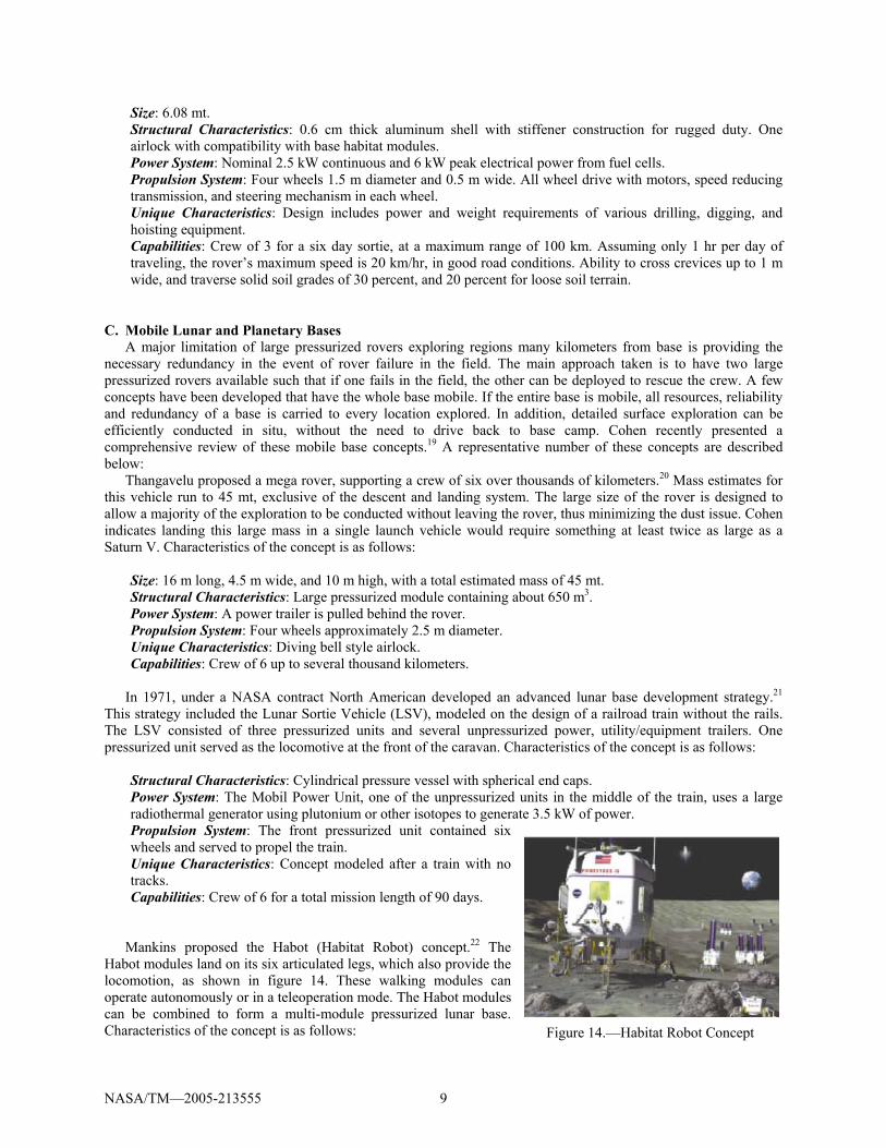
Mankins proposed the Habot (Habitat Robot) concept.22 The
Habot modules land on its six articulated legs, which also provide the locomotion, as shown in figure 14. These walking modules can operate autonomously or in a teleoperation mode. The Habot modules can be combined to form a multi-module pressurized lunar base. Characteristics of the concept is as follows: Figure 14.—Habitat Robot Concept
NASA/TM—2005-213555 10
Size: up to 5 m diameter units. 10 mt per unit. Structural Characteristics: Hexagonal pressure vessels to allow clustering with other units. Power System: Photovoltaic cells on the top of the modules produce the power required during the lunar day (14 earth days). Propulsion System: Six articulated legs per unit. Unique Characteristics: Movement will be conducted during the lunar day. The units will cluster and remain stationary at minimum power levels for the lunar nights. Capabilities: Crew of 6 for a 100 day lunar mission, with a number of Habot units.
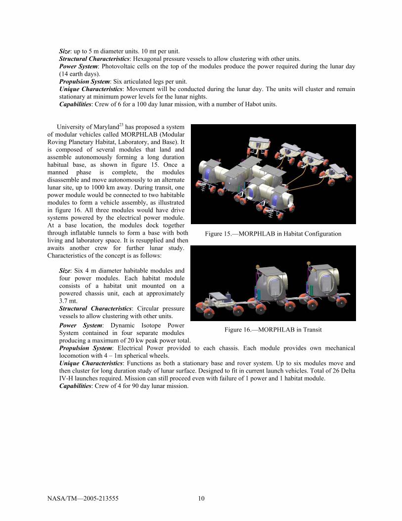
University of Maryland23 has proposed a system
of modular vehicles called MORPHLAB (Modular Roving Planetary Habitat, Laboratory, and Base). It is composed of several modules that land and assemble autonomously forming a long duration habitual base, as shown in figure 15. Once a manned phase is complete, the modules disassemble and move autonomously to an alternate lunar site, up to 1000 km away. During transit, one power module would be connected to two habitable modules to form a vehicle assembly, as illustrated in figure 16. All three modules would have drive systems powered by the electrical power module. At a base location, the modules dock together through inflatable tunnels to form a base with both living and laboratory space. It is resupplied and then awaits another crew for further lunar study. Characteristics of the concept is as follows:
Size: Six 4 m diameter habitable modules and four power modules. Each habitat module consists of a habitat unit mounted on a powered chassis unit, each at approximately 3.7 mt. Structural Characteristics: Circular pressure vessels to allow clustering with other units. Power System: Dynamic Isotope Power System contained in four separate modules producing a maximum of 20 kw peak power total. Propulsion System: Electrical Power provided to each chassis. Each module provides own mechanical locomotion with 4 – 1m spherical wheels. Unique Characteristics: Functions as both a stationary base and rover system. Up to six modules move and then cluster for long duration study of lunar surface. Designed to fit in current launch vehicles. Total of 26 Delta IV-H launches required. Mission can still proceed even with failure of 1 power and 1 habitat module. Capabilities: Crew of 4 for 90 day lunar mission.
Figure 15.—MORPHLAB in Habitat Configuration
Figure 16.—MORPHLAB in Transit
NASA/TM—2005-213555 11
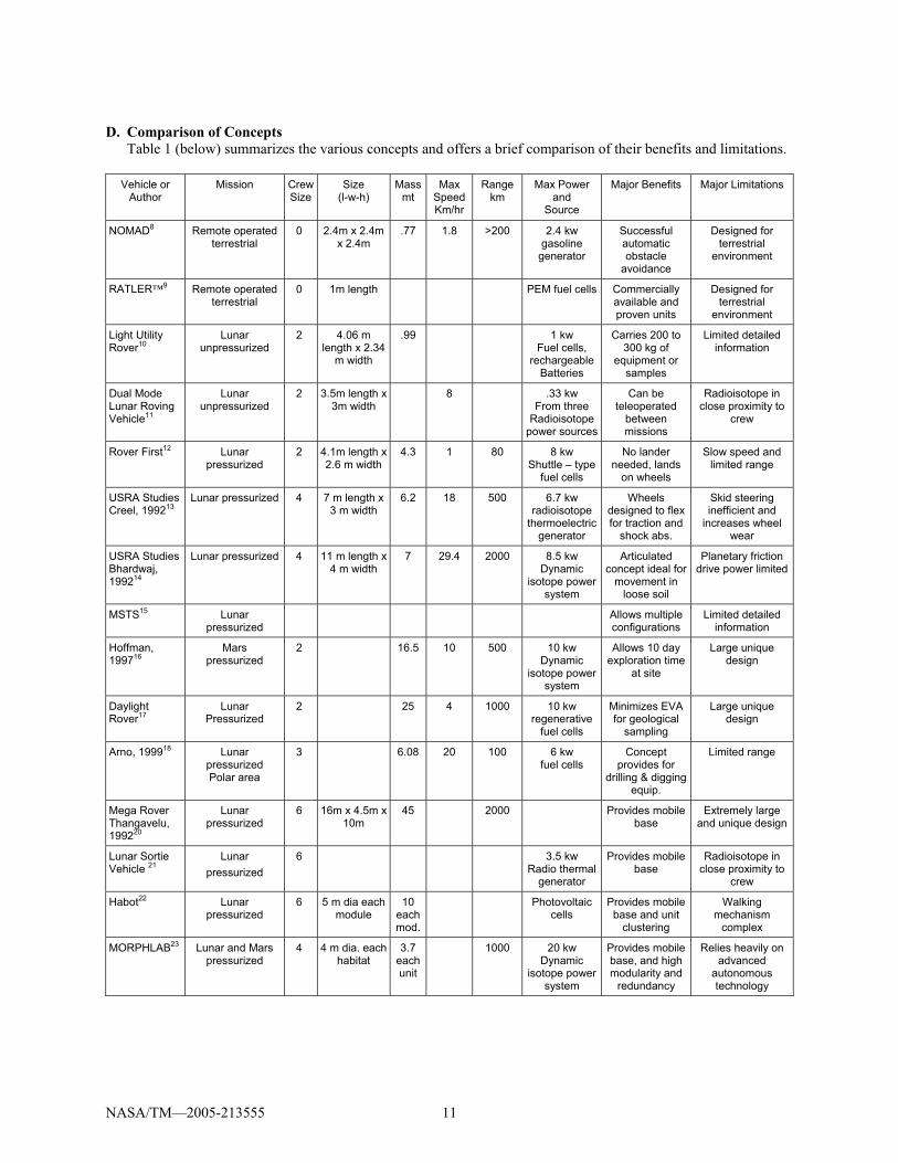
D. Comparison of Concepts Table 1 (below) summarizes the various concepts and offers a brief comparison of their benefits and limitations.
Vehicle or Author
Mission Crew Size
Size (l-w-h)
Massmt
Max SpeedKm/hr
Range km
Max Power and
Source
Major Benefits Major Limitations
NOMAD8 Remote operated terrestrial
0 2.4m x 2.4m x 2.4m
.77 1.8 >200 2.4 kw gasoline
generator
Successful automatic obstacle
avoidance
Designed for terrestrial
environment
RATLER™9 Remote operated terrestrial
0 1m length PEM fuel cells Commercially available and proven units
Designed for terrestrial
environment
Light Utility Rover10
Lunar unpressurized
2 4.06 m length x 2.34
m width
.99 1 kw Fuel cells,
rechargeable Batteries
Carries 200 to 300 kg of
equipment or samples
Limited detailed information
Dual Mode Lunar Roving Vehicle11
Lunar unpressurized
2 3.5m length x 3m width
8 .33 kw From three
Radioisotope power sources
Can be teleoperated
between missions
Radioisotope in close proximity to
crew
Rover First12 Lunar pressurized
2 4.1m length x 2.6 m width
4.3 1 80 8 kw Shuttle – type
fuel cells
No lander needed, lands
on wheels
Slow speed and limited range
USRA Studies Creel, 199213
Lunar pressurized 4 7 m length x 3 m width
6.2 18 500 6.7 kw radioisotope
thermoelectric generator
Wheels designed to flex for traction and
shock abs.
Skid steering inefficient and
increases wheel wear
USRA Studies Bhardwaj, 199214
Lunar pressurized 4 11 m length x 4 m width
7 29.4 2000 8.5 kw Dynamic
isotope power system
Articulated concept ideal for
movement in loose soil
Planetary friction drive power limited
MSTS15 Lunar pressurized
Allows multiple configurations
Limited detailed information
Hoffman, 199716
Mars pressurized
2 16.5 10 500 10 kw Dynamic
isotope power system
Allows 10 day exploration time
at site
Large unique design
Daylight Rover17
Lunar Pressurized
2 25 4 1000 10 kw regenerative
fuel cells
Minimizes EVA for geological
sampling
Large unique design
Arno, 199918 Lunar pressurized Polar area
3 6.08 20 100 6 kw fuel cells
Concept provides for
drilling & digging equip.
Limited range
Mega Rover Thangavelu, 199220
Lunar pressurized
6 16m x 4.5m x 10m
45 2000 Provides mobile base
Extremely large and unique design
Lunar Sortie Vehicle 21
Lunar pressurized
6 3.5 kw Radio thermal
generator
Provides mobile base
Radioisotope in close proximity to
crew
Habot22 Lunar pressurized
6 5 m dia each module
10 each mod.
Photovoltaic cells
Provides mobile base and unit
clustering
Walking mechanism
complex
MORPHLAB23 Lunar and Mars pressurized
4 4 m dia. each habitat
3.7each unit
1000 20 kw Dynamic
isotope power system
Provides mobile base, and high modularity and
redundancy
Relies heavily on advanced
autonomous technology
NASA/TM—2005-213555 12
It is difficult to provide a more detailed comparison of the concepts as many lack specific details, and are, for the most part, only high level notional designs. In addition, the final missions will dictate the actual characteristics required of the various rovers needed. Collectively, the concepts above can provide some basic insight into rover design paradigms. Individually, the concepts can also provide unique ideas that can be very beneficial for any rover design.
Collectively, the following design trends can be seen in a majority of the concepts:
• Most concepts are unique, designed for specific uses or missions. • Only the MORPHLAB concept explores modularity, although it is within a mission scenario. • No concept addresses modularity across all possible Lunar/Mars missions. • All except the Habot concept rely on motors propelling each wheel separately. No concept investigates a
distributed mechanical or hydraulic propulsion system. • All except the Habot concept have wheeled propulsive elements. • Most concepts developed for Lunar mission only. • Very few concepts discuss interior crew accommodations. Noise levels due to pumps, motors, fans, etc.,
may be significant in the confines of the pressurized rovers. Current noise levels in some areas of the space station exceed 70 decibels, which is akin to standing next to a freeway.
The following benefits inherent in some of the concepts can be very beneficial for any rover design:
• The dual use rover concept can significantly reduce the amount of equipment required to be placed on a planetary surface. A rover that can be teleoperated during the unmanned missions, and, with some modifications, can be crewed in manned missions can be very efficient and economical.
• Placing rovers on the surface without a lander can save a large amount of weight that can be used to carry other supplies.
• Rovers designed with articulated motion capabilities will be capable of negotiating terrain even tracked vehicles can get stuck in.
• Highly controllable manipulating arms on a rover in conjunction with a small sample airlock can reduce EVA needs and dust infiltration problems.
• Modularity, even if only within a mission scenario, can efficiently increase redundancy.
III. Mission and Environmental Challenges
A. Mission Challenges The first post Apollo set of human Lunar surface missions are expected to last between 4 and 14 days. The next
set of missions will be longer, possibly in the range of 42 and 98 days. The landing regions for these missions will be selected from data acquired by orbital missions to the Moon (the first of which is the Lunar Reconnaissance Orbiter) that identify potential landing sites which are safe, near possible water ice resources, and provide appropriate environmental conditions for the system design (i.e. lighting, solar power, thermal). These target landing sites will be identified from orbital data and the human lander will “precision” land within 100s of meters of the targeted sites. One of the most desirable sites is the south polar region, at the rim of Shackleton crater. This site is near possible ice deposits, and is most “Mars” like in surface temperatures. However, steep rim slopes and potentially deep regolith deposits at this location introduce formidable surface mobility challenges.
During their stay on the surface, the astronauts will most likely conduct teleoperated reconnaissance of the landing region before any EVA activities. After initial EVAs to check-out equipment, the astronauts will travel to desirable sites and select rock and soil samples from the surface and subsurface (via drilling). Drilling to approximately 10 meters will probably be common, and in some instances drilling up to several hundred meters may be required. In order to perform this sample selection and collection, the astronauts will be assisted by robotic vehicles. Upon return to the habitat, they will perform measurements of the samples for geochemistry, volatiles, and initial age determination using their in situ laboratory instruments. During the first set of lunar surface missions (4 to 14 day duration), the astronauts will require unpressurized rovers for short exploration missions, and for site preparation, base assembly and maintenance. For the longer duration missions (42 to 98 day duration), the astronauts will require pressurized rovers to traverse longer distances, possibly up to 50 km, in search of water ice. The rovers will also be needed to deploy nuclear and/or solar power systems elements. Rovers will also be needed to position and initiate in situ resource utilization systems for evaluation and technology demonstration. The longer duration
NASA/TM—2005-213555 13
lunar missions are primarily aimed at validating technologies and methods for long duration Mars surface missions. It is thus crucial that all rover technologies developed for lunar surface missions have a direct evolution to the systems that will be required on Mars.
Human missions to Mars will have similar rover requirements. Mars missions will require longer stays, possibly in the range of 18 to 20 months.16 In addition, long range surface exploration sorties are projected to be in the range of 500 km. Because the first manned Mars mission will be, most likely, long duration, both unpressurized and pressurized rovers will be needed at the start.
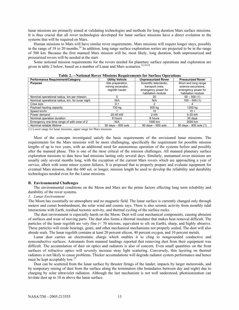
Some notional mission requirements for the rovers needed for planetary surface operations and exploration are given in table 2 below, based on a number of Lunar and Mars scenarios.16,18,24
Table 2.—Notional Rover Missions Requirements for Surface Operations
Performance Requirement/Category Utility Vehicle Unpressurized Rover Pressurized Rover Purpose Site preparation,
mining excavator, regolith hauler
Scientific telerobotic, transport crew,
emergency power for habitation module
Short and long range science excursions,
emergency power for habitation module
Nominal operational radius, km per mission 5 20 50 – 500 (1) Nominal operational radius, km, for lunar night N/A N/A 100 – 500 (1) Crew size 0-1 2 4 Payload hauling capacity 750 kg 500 kg 1200 kg Speed km/hr 1 10 10 + Power demand 20-40 kW 2 kW 5-20 kW Nominal operation duration 8 hours 8 hours 30 days Emergency one-time range of with crew of 2 N/A 1000 km 2000 km Nominal reliable lifetime 90 days – 600 sols 90 days – 600 sols 90 days – 600 sols (1)
(1) Lower range for lunar missions, upper range for Mars missions Most of the concepts investigated satisfy the basic requirements of the envisioned lunar missions. The
requirements for the Mars missions will be more challenging, specifically the requirement for possible mission lengths of up to two years, with an additional need for autonomous operation of the systems before and possibly after the manned phase. This is one of the most critical of the mission challenges. All manned planetary surface exploration missions to date have had missions lasting only several days. Similarly, unmanned rover missions are usually only several months long, with the exception of the current Mars rovers which are approaching a year of service, albeit with some minor system failures. It is proposed that to properly prepare and evaluate equipment for eventual Mars mission, that the 600 sol, or longer, mission length be used to develop the reliability and durability technologies needed even for the Lunar missions.
B. Environmental Challenges The environmental conditions on the Moon and Mars are the prime factors effecting long term reliability and
durability of the rover systems. 1. Lunar Environment The Moon has essentially no atmosphere and no magnetic field. The lunar surface is currently changed only through meteor and comet bombardment, the solar wind and cosmic rays. There is also seismic activity from monthly tidal interactions with Earth, residual tectonic activity, and thermal cycling of the surface rocks.
The dust environment is especially harsh on the Moon. Dust will coat mechanical components, causing abrasion of surfaces and wear of moving parts. The dust also forms a thermal insulator that makes heat removal difficult. The particles of the lunar regolith are very fine (< 70 microns, equivalent to silt on Earth), sharp, and highly abrasive. These particles will erode bearings, gears, and other mechanical mechanisms not properly sealed. The dust will also abrade seals. The lunar regolith contains at least 20 percent silicon, 40 percent oxygen, and 10 percent metals.
Lunar dust carries an electrostatic charge which enables it to cling to nongrounded conductive and nonconductive surfaces. Astronauts from manned landings reported that removing dust from their equipment was difficult. The accumulation of dust on optics and radiators is also of concern. Even small quantities on the front surfaces of refractive optics will severely increase stray light scattering. Conversely, thin layering on thermal radiators is not likely to cause problems. Thicker accumulations will degrade radiator system performance and hence must be kept acceptably low.25
Dust can be scattered from the lunar surface by thruster firings of the lander, impacts by larger meteoroids, and by temporary raising of dust from the surface along the terminators (the boundaries between day and night) due to charging by solar ultraviolet radiation. Although the last mechanism is not well understood, photoionization can levitate dust up to 10 m above the lunar surface.
NASA/TM—2005-213555 14
The dominant source of suspended dust will be the rover interaction with the soil. As seen in video footage of the Apollo 17 LRV, the amount of dust sprayed from the wheels was large and reached heights of over two meters. For future lunar exploration, human activity, excavation and in situ resource utilization activities will also contribute to dust generation. Since the lunar atmosphere is essentially a vacuum, the lifted particles do not remain suspended, but quickly return to the surface, with each particle following a ballistic trajectory.
The thermal environment resulting from the long day/night cycle (~ 2 weeks each) will mean a long period of intense heating followed by a similar period of intense cold. The thermal environment around a rover will consist of direct solar flux from the sun, reflected lunar albedo flux, and infrared radiation directly from the lunar surface.
The solar flux is the amount of power that passes through a given area at a given distance from the sun. The nominal value at the Earth’s (or Moon’s) distance from the sun is called the Solar Constant, and the average value is 1358W/m2.
The Moon’s albedo (reflectivity) is less than 10 percent. This means that 90 percent of incipient solar radiation heats the surface.26 The amount of reflected energy that impinges on the rover is dependant on the orientation of the rover and is much smaller in magnitude than direct solar radiation and IR radiation from the lunar surface. The lunar surface acts as a grey body source at the temperature of the surface. This surface temperature varies according to latitude and the time in the lunar day/night cycle. The extremes that the rover expects to see are +120 to –150 °C. These extremes are similar to going from super heated steam to liquid nitrogen temperatures. Areas near the poles can be more benign, and vary from approximately –63 to –43 °C, assuming a mission profile that avoids lunar night. Of particular concern, however, is prolonged rover operations in permanently shadowed craters at the lunar South poles, where water ice is most likely to be found. Here ambient temperatures have been estimated at < –260 °C. Operation at this extreme cold environment will require additional power for many heaters, or advanced technologies to withstand the cold, such as ultra-low temperature lubrication and materials.
The radiation exposure, with no appreciable atmosphere or magnetic field for protection, can be as high as that of interplanetary space in the solar system. Solar and cosmic radiation concerns will dominate human protection as well as electrical component protection from single event upsets and hard failures. Degradation of optical components will also be a factor. The rovers will encounter the harsh space ionizing radiation environment: large fluxes of low-energy solar wind particles, smaller fluxes of high-energy galactic cosmic rays, and occasional intense particle fluxes emitted by solar flares. In addition to the ionizing radiation that reaches the lunar surface, soft x-rays and ultraviolet light are also present in significant quantities.
The solar wind particles are the most numerous particles striking the rovers, but due to their comparative low-energy, are of less concern than galactic cosmic rays and solar flare events.27 Solar flares can occur several times a year, and emit a large number of particles at relatively high energies (1–100MeV). These flares can last from several hours to many days, and have the potential to bombard the rovers with high energy particles that can damage the rover's surface and structural integrity and electronic components. Rovers at moderate to far distances away from base must be able to protect the crew from these radiation sources when it is not possible to return to base in enough time. These energetic protons ionize optical materials and since they are massive they create defects throughout the bulk of those materials. This radiation must be considered when choosing structural materials and component placement within the rover.
Cosmic rays occur very infrequently (~4 protons/cm2-sec), but are very high energy. While the number of particles is not an issue, their high energy can cause damage to electrical components. A single particle can damage an electrical component and cause its failure through energy loss and elastic and inelastic scattering processes.
Soft x-rays and ultraviolet light affect surface coatings and optics, due to their energy levels in the solar electromagnetic spectrum. Solar ultraviolet and soft x-ray photons are sufficiently energetic to induce defect centers in optical materials, and can cause darkening throughout shallow depths.
The vacuum environment will result in material outgassing and will promote degradation of materials and optical components from exposure to ultraviolet radiation. The hard vacuum precludes the use of many common plastics and rubbers whose strength and pliability become reduced by out gassing of their volatile components. Out gassed materials can also collect on optical and sensing surfaces, which can reduce their effectiveness. Organic, organo-metallic, and organo-silane polymers (and copolymers) which are fully reacted, and consequently have low vapor pressures, may be used if their optical and/or mechanical properties are stable over the expected influences of solar radiation and their temperatures are maintained above “glass” phase transitions. Micrometeorite protection will be a factor with no protective atmosphere. It is suggested that two to three millimeters of a tough composite material can provide effective shielding from micrometeoroids in the milligram mass range traveling at 13 to 18 km/sec.14 The lunar environment possesses a hard vacuum with 2 orders of magnitude fewer particles per unit volume than low earth orbit.
NASA/TM—2005-213555 15
The terrain of the lunar surface has been defined by meteor strikes. Continual impacts of micrometeoroids have resulted in an extremely fine, loosely-compacted soil. Many of the large-scale features, such as steep crater walls and large boulders, are insurmountable obstacles to the rover. As mentioned earlier, one of the most desirable sites is the south polar region, at the rim of Shackleton Crater. Long-distance sorties at these sites will require a rover to traverse steep crater walls comprised of friable surface materials. Shackleton Crater’s slope angles have not been measured, but regular lunar craters of Shackleton’s diameter typically have slopes approaching the lunar regolith angle of repose, 35º to 40º. The locomotion limit for typical lunar rovers on friable slopes is in the range of 30º to 35º.
Trafficability on disturbed lunar and Martian soils due to grading, backfilling, or other soil excavation, is also not well understood.28 These soils may not be able to support loads well, possibly resulting in soil behavior similar to quick-sand or snow. Compact soil can carry loads well because of a rigid network of connections between grains. It is possible that disturbed planetary soil may expand too much and reduce its load carrying capacity. The maximum contact pressure for undisturbed lunar soil is proposed to be 7 kN/m2 (the lunar rover averaged about 4.2 kN/m2).18 This is an important factor when designing wheels or other surface traction device for rovers. 2. Mars Environment29
Mars has an atmosphere that is about 1percent of the density of Earth’s atmosphere. It is composed primarily of carbon dioxide. Mars lacks a global magnetic field, but does have localized magnetic anomalies. Mars also has a fairly eccentric orbit resulting in significant perihelion and aphelion distances and producing differences in the Martian seasons. The duration of spring in the northern hemisphere is 194 sols, while autumn is 143 sols. A sol is a mean Martian solar day (24 h, 37 m).
Topographic relief on Mars is much greater than on Earth or the Moon. Highlands occur mainly in the southern hemisphere; lowland mainly in the northern hemisphere. The southern highlands are heavily cratered. Fluvial and other erosion process have acted greatly in the southern highlands. The northern plains of Mars are relatively smooth but with variations indicating sedimentary, volcanic, and aeolian materials.
Based on Viking lander and Mars Pathfinder imagery, the surface material on Mars can be divided into rocks, soil and drift material. Across the three landing sites, rocks that cover 8 to 16 percent of the surface range in size from pebbles to over 1-m in diameter. Soil covers 80 to 90 percent of the landing sites, having the characteristics of moderately dense terrestrial soil with significant clay or silt-sized particles. Drift material is very fine grained and porous. The presence of oxidants is inferred from Viking data.
Pressure, temperature and wind speed are the most important atmospheric factors that influence the design for surface mobility systems. Pressure variations occur diurnally, over periods of days and through seasonal changes as the carbon dioxide atmosphere condenses at the poles during winter and sublimes during summer.
Temperatures vary throughout the day, throughout the season and with latitude. At the Viking landing sites, temperatures were measure at a height of 1-m. above the ground. Daily temperatures varied by 40 °C on average. Variation was less during global dust storms. The coldest daily temperatures occurred just before dawn. Seasonally, temperatures varied from –107 °C in the winter to –18 °C in the summer. Pathfinder measured similar temperature variations, but temperatures were about 10 °C higher. At the poles, the surface temperature is estimated to be as low as –143 °C. The warmest soil temperature in the summer tropics could reach 27 °C. Data from the Hubble Space Telescope suggest that, on average, Mars is 20 °C cooler than during the Viking missions.
Wind speeds are 2 to 7 m/s in the summer, rising to 5 to 10 m/s in the winter. During dust storms, speeds can increase to 30 m/s. Wind direction varies 360-degrees during a sol. Data from Pathfinder suggest that dust devils can be a daily occurrence. Global and regional dust storms are common. Local dust storms probably occur during all seasons; Global dust storms occur in the southern spring and summer. Global dust storms develop when regional centers of dust activity expand; they do not start spontaneously.
C. Environmental Effects on Rover Designs In summary, major projected mission and environmental factors that will impact rover design are:
• Long duration Mars mission will require two year continuous service, with a number of years in standby or autonomous mode before and after the manned segment. Resistance to long term environmental affects will be crucial.
• Dust abrasion of seals and surfaces. Dust accumulation from normal equipment operation and dust storms (Mars).
• Effects of large temperature effects, and effects of continuous operation in extreme cold permanently shaded areas of the Moon.
• Long term radiation effects on seals, structural materials and electronics systems.
NASA/TM—2005-213555 16
• Effects of terrain: steep craters, soil weight bearing capability, and dynamic effects due to high speed operation over rough terrain.
• Rover concepts spanning all Lunar and Mars missions will require adaptable/tunable suspensions to address different gravities between the Moon and Mars, and different mission profiles within both.
Due to a lack of detailed data on the various concepts investigated, a comprehensive comparison on how each design addresses the environmental challenges is not possible. It is, however, possible to develop some general conclusions based on the concept characteristics and how they may or may not withstand the environmental challenges.
• Only one concept addressed the maximum pressure allowance for the soil. Design tradeoffs may be needed for the larger vehicles between rolling resistance and soil pressure.
• Dust will be a critical problem for all mechanical systems. Seals for these systems must be resistant to the dust and radiation environments. Failure of seals will result in mechanism failure.
• Air locks will be necessary for all pressurized vehicles. A few concepts called for the same system as the Apollo Lunar Module, where the whole chamber is depressurized during EVA.
• System reliability is critical and highly challenging as operational lifetimes are extended to meet mission requirements. Health management technologies, mentioned in some of the concepts, will be required for all critical subsystems.
IV. Design Challenges and Strategies The design of a manned space system requires a systems level approach in determining optimum features and
characteristics to produce a reliable system that meets all mission and safety requirements. Arno18 presents an excellent example of a systems based design strategy that incorporates many aspects, including cost, mission requirements, etc., early in the design process. The design strategies presented herein can be considered to be a continuation of Arno’s work in that it provides more detailed strategies into the actual idea development, design, and evaluation process. Examples are given to illustrate key points.
A. Design Challenges From investigating existing concepts and the environmental and mission challenges, a set of general design
challenges can be assembled. A general list of design challenges for planetary surface exploration vehicles is presented below:
• Minimal weight and size • Reliable long term operation of all critical systems • Ability to survive and operate in abrasive and dusty environment • Safety of personnel in extreme radiation and thermal conditions • Efficient power utilization and transmission • Ability to maneuver in majority of terrains on Moon/Mars • Ability to package and land large rover systems • Modular systems that can be utilized across all missions (Lunar short, Lunar long, Mars)
B. Design Cycle The design cycle starts with a set of mission requirements derived from reference missions and design challenges
as listed above. Concepts are developed using trade studies and other design tools. Early conceptual design is critical to the eventual success of these systems. This process must be effectively managed with well defined milestones. It has been proven that conceptual design is a critical tool to flush out mission and engineering requirements so all challenges and problems can be well understood before entering into the development phase. Paper studies are not sufficient to get to the real challenges that will burden and delay a development schedule and drive cost overruns. These early concepts most likely will be carried out by NASA centers. This is an iterative process with the final product being a set of requirements that can be used to contract for full design and development.
A nonpressurized rover capability will be required as part of the first series of short-duration lunar surface missions. The challenge is to make this system modular in nature and evolvable to a pressurized system needed in the long duration lunar and Mars missions. Short duration mission designs will be forced to sacrifice an optimal design in order to be compatible with subsequent missions. The initial short duration Lunar missions will be used to
NASA/TM—2005-213555 17
verify systems on the lunar surface that will be modular in nature and contain many of the same modules that will be used in the rover systems required for the long duration missions.
All designs must be flexible to allow for use of new technologies that evolve during the long development cycle that spans the Exploration spirals. What has a low Technology Readiness Level (TRL) today, will most certainly be high TRL tomorrow since this program will evolve over several decades. However, to control costs and schedule within each spiral, a discipline approach must be taken to address when a low TRL can be used in the development cycle. Reviews must be held to either approve or replace technologies that are not ready for inclusion in the detailed design phase. Cut off dates also must be established and rigorously adhered to prevent low TRL technologies from being introduced once detailed design has began.
It is crucial to do a thorough review of what has been done by holding discussions with traditional industry partners and other organizations to see what has been done and to see how far these organizations have taken their concepts. Thorough reviews on all previous work and publications must be completed as part of the early conceptual design phases. What has worked, what hasn’t and what is feasible with today or tomorrow’s technology must be well understood.
Innovation must be encouraged. Even though there have been many ideas proposed over the last 30 years for the many types of surface mobility concepts, there are many other ideas that could be generated. The final product is bound to be very different from what has been proposed. A rover like that used during the Apollo era would be easy to recreate; however, it does not help us progress to the long duration missions. A pressurized rover or even a moveable habitat base has no design heritage. Some ideas appear unpractical in our day of low budgets and small launch vehicles; however, no idea should be dismissed offhand. A module on walking legs may appear impractical, but its advantages might outweigh its disadvantages.
Wherever possible, we must incorporate technologies being developed under other programs that have potential for addressing design challenges. An example of this is incorporating face gear technologies being developed by helicopter manufacturers for main transmission drives.30 Face gears have the potential of reducing weight and size of mechanical speed reduction drives while maintaining reliability and durability necessary for aircraft applications. Most rover concepts select harmonic a drive in each wheel to reduce speed from the motor to the wheel. Harmonic drives are excellent for low power and limited life applications; however, the high sliding and wear associated with harmonic drives make it a poor choice for high power, long life rover drive mechanisms. Face gears may be capable of providing the power, reliability, and size needed for larger rovers.
C. Modularity In order to support the spiral development method of the new exploration initiative, modularity is a crucial
design philosophy that must be employed in development of all major elements of the system. Surface mobility vehicles will build upon one another as we advance from short to long duration missions. The most basic of the modules will be used to validate design, prove reliability, operation and function. The basic module will then be used as building blocks for larger vehicles that have both greater mass carrying capacity and longer duration. Modularity provides a specific form and function on common subsystems making up different systems of distinct and separate system function. Modularity should not only be based upon form and function of an element, but also life-cycle characteristics such as manufacture, assembly, service, and recycling
Modularity is necessary across the projected design spirals because of evolving requirements will require flexibility and ability to adapt to changing requirements. Modularity will permit lower individual launch mass so that hardware can be delivered in smaller elements thus allowing utilization of existing launch vehicles. Modularity is important from a safety and maintenance standpoint. It will facilitate redundancy and easy change out of modules due to failure or the need to upgrade. This would make all systems more reliable since spare modules could be stored or taken from other systems in the event of a failure.
Modularity would also permit scaling. A modular power system would permit chaining of modules or exchanging modules of different power levels. A great benefit could be achieved, if by simply adding or exchanging a second power module the power rating could be increased. For example, adding a 1 Kw module to another 1 Kw would result in a single 2 Kw power capacity or substituting a 2Kw module for a 1 Kw in the same location would permit power upgrade.
In the overall design of the rover system, development of modular frames, propulsion mechanisms, etc., may enable portions of a large pressurized rover to be built from smaller unpressurized subsystems. In addition, construction vehicles can have the same chassis as an unpressurized rover. Adding soil excavating attachments, and extra power units and propulsion mechanisms can convert light duty rovers to heavy construction vehicles. This not only reduces launch mass, but also complexity and uniqueness. This approach increases redundancy by having spare modules available from other units not in use.
NASA/TM—2005-213555 18
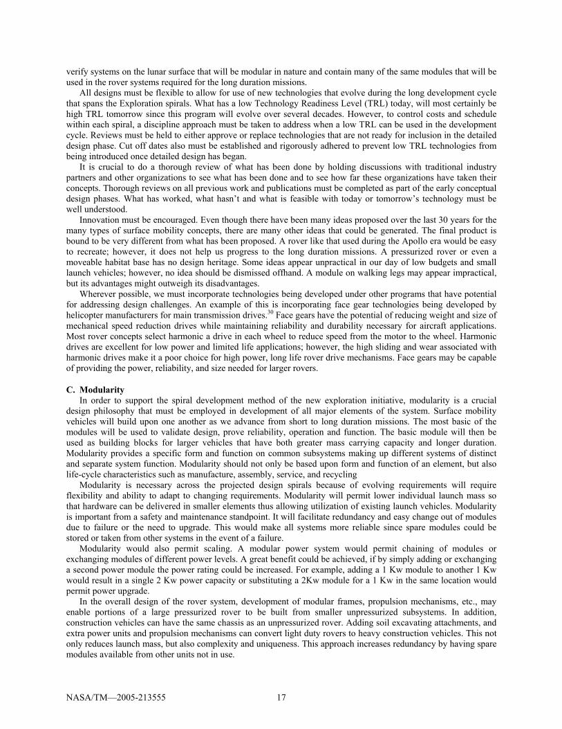
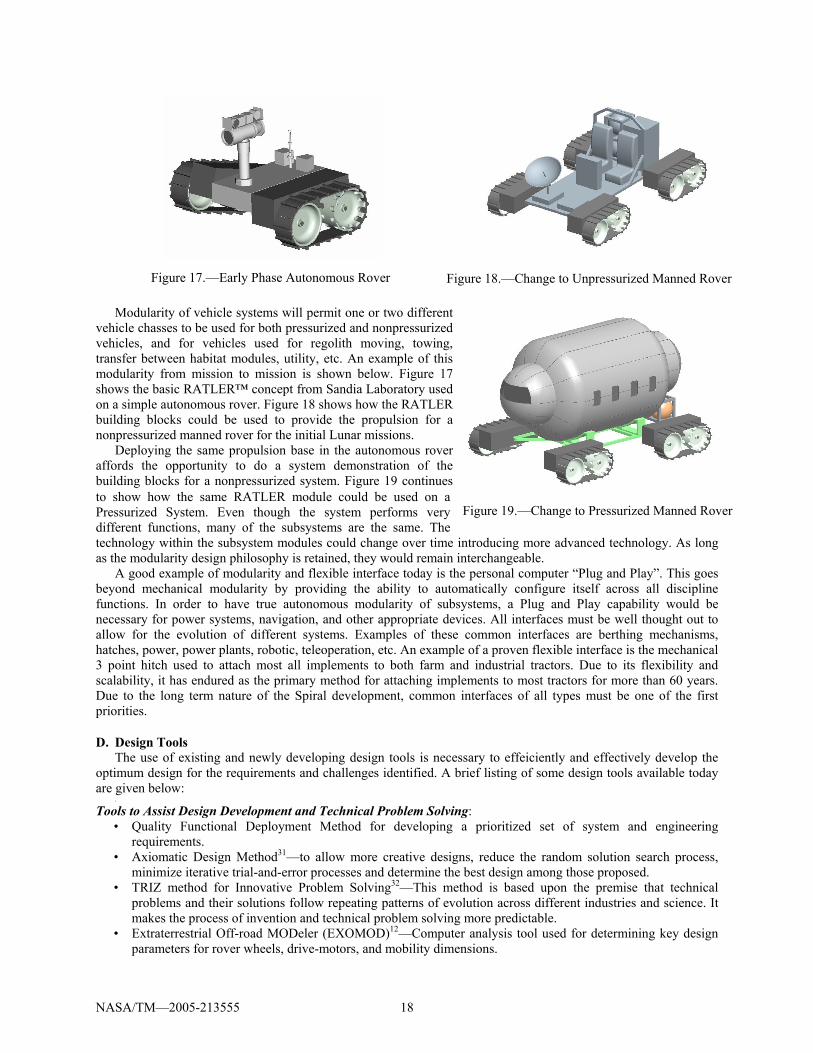
Modularity of vehicle systems will permit one or two different
vehicle chasses to be used for both pressurized and nonpressurized vehicles, and for vehicles used for regolith moving, towing, transfer between habitat modules, utility, etc. An example of this modularity from mission to mission is shown below. Figure 17 shows the basic RATLER™ concept from Sandia Laboratory used on a simple autonomous rover. Figure 18 shows how the RATLER building blocks could be used to provide the propulsion for a nonpressurized manned rover for the initial Lunar missions.
Deploying the same propulsion base in the autonomous rover affords the opportunity to do a system demonstration of the building blocks for a nonpressurized system. Figure 19 continues to show how the same RATLER module could be used on a Pressurized System. Even though the system performs very different functions, many of the subsystems are the same. The technology within the subsystem modules could change over time introducing more advanced technology. As long as the modularity design philosophy is retained, they would remain interchangeable.
A good example of modularity and flexible interface today is the personal computer “Plug and Play”. This goes beyond mechanical modularity by providing the ability to automatically configure itself across all discipline functions. In order to have true autonomous modularity of subsystems, a Plug and Play capability would be necessary for power systems, navigation, and other appropriate devices. All interfaces must be well thought out to allow for the evolution of different systems. Examples of these common interfaces are berthing mechanisms, hatches, power, power plants, robotic, teleoperation, etc. An example of a proven flexible interface is the mechanical 3 point hitch used to attach most all implements to both farm and industrial tractors. Due to its flexibility and scalability, it has endured as the primary method for attaching implements to most tractors for more than 60 years. Due to the long term nature of the Spiral development, common interfaces of all types must be one of the first priorities.
D. Design Tools The use of existing and newly developing design tools is necessary to effeiciently and effectively develop the
optimum design for the requirements and challenges identified. A brief listing of some design tools available today are given below:
.
Tools to Assist Design Development and Technical Problem Solving: • Quality Functional Deployment Method for developing a prioritized set of system and engineering
requirements. • Axiomatic Design Method31—to allow more creative designs, reduce the random solution search process,
minimize iterative trial-and-error processes and determine the best design among those proposed. • TRIZ method for Innovative Problem Solving32—This method is based upon the premise that technical
problems and their solutions follow repeating patterns of evolution across different industries and science. It makes the process of invention and technical problem solving more predictable.
• Extraterrestrial Off-road MODeler (EXOMOD)12—Computer analysis tool used for determining key design parameters for rover wheels, drive-motors, and mobility dimensions.
Figure 17.—Early Phase Autonomous Rover Figure 18.—Change to Unpressurized Manned Rover
Figure 19.—Change to Pressurized Manned Rover
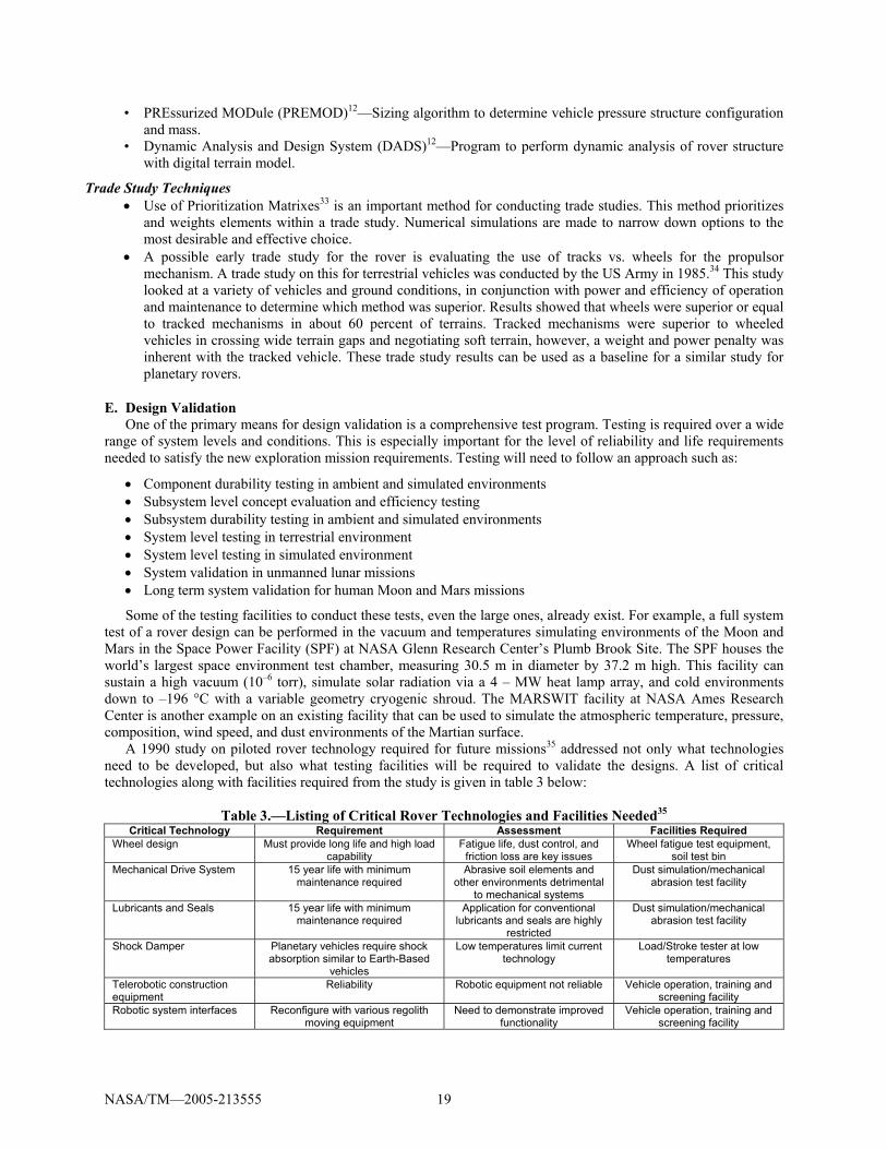
NASA/TM—2005-213555 19
• PREssurized MODule (PREMOD)12—Sizing algorithm to determine vehicle pressure structure configuration and mass.
• Dynamic Analysis and Design System (DADS)12—Program to perform dynamic analysis of rover structure with digital terrain model.
Trade Study Techniques • Use of Prioritization Matrixes33 is an important method for conducting trade studies. This method prioritizes
and weights elements within a trade study. Numerical simulations are made to narrow down options to the most desirable and effective choice.
• A possible early trade study for the rover is evaluating the use of tracks vs. wheels for the propulsor mechanism. A trade study on this for terrestrial vehicles was conducted by the US Army in 1985.34 This study looked at a variety of vehicles and ground conditions, in conjunction with power and efficiency of operation and maintenance to determine which method was superior. Results showed that wheels were superior or equal to tracked mechanisms in about 60 percent of terrains. Tracked mechanisms were superior to wheeled vehicles in crossing wide terrain gaps and negotiating soft terrain, however, a weight and power penalty was inherent with the tracked vehicle. These trade study results can be used as a baseline for a similar study for planetary rovers.
E. Design Validation One of the primary means for design validation is a comprehensive test program. Testing is required over a wide
range of system levels and conditions. This is especially important for the level of reliability and life requirements needed to satisfy the new exploration mission requirements. Testing will need to follow an approach such as:
• Component durability testing in ambient and simulated environments • Subsystem level concept evaluation and efficiency testing • Subsystem durability testing in ambient and simulated environments • System level testing in terrestrial environment • System level testing in simulated environment • System validation in unmanned lunar missions • Long term system validation for human Moon and Mars missions
Some of the testing facilities to conduct these tests, even the large ones, already exist. For example, a full system test of a rover design can be performed in the vacuum and temperatures simulating environments of the Moon and Mars in the Space Power Facility (SPF) at NASA Glenn Research Center’s Plumb Brook Site. The SPF houses the world’s largest space environment test chamber, measuring 30.5 m in diameter by 37.2 m high. This facility can sustain a high vacuum (10–6 torr), simulate solar radiation via a 4 – MW heat lamp array, and cold environments down to –196 °C with a variable geometry cryogenic shroud. The MARSWIT facility at NASA Ames Research Center is another example on an existing facility that can be used to simulate the atmospheric temperature, pressure, composition, wind speed, and dust environments of the Martian surface.
A 1990 study on piloted rover technology required for future missions35 addressed not only what technologies need to be developed, but also what testing facilities will be required to validate the designs. A list of critical technologies along with facilities required from the study is given in table 3 below:
Table 3.—Listing of Critical Rover Technologies and Facilities Needed35
Critical Technology Requirement Assessment Facilities Required Wheel design Must provide long life and high load
capability Fatigue life, dust control, and
friction loss are key issues Wheel fatigue test equipment,
soil test bin Mechanical Drive System 15 year life with minimum
maintenance required Abrasive soil elements and
other environments detrimental to mechanical systems
Dust simulation/mechanical abrasion test facility
Lubricants and Seals 15 year life with minimum maintenance required
Application for conventional lubricants and seals are highly
restricted
Dust simulation/mechanical abrasion test facility
Shock Damper Planetary vehicles require shock absorption similar to Earth-Based
vehicles
Low temperatures limit current technology
Load/Stroke tester at low temperatures
Telerobotic construction equipment
Reliability Robotic equipment not reliable Vehicle operation, training and screening facility
Robotic system interfaces Reconfigure with various regolith moving equipment
Need to demonstrate improved functionality
Vehicle operation, training and screening facility
NASA/TM—2005-213555 20
V. Production and Delivery Strategies
A. Teaming Strategies for Design and Production The successful design, development, and validation of a highly reliable surface exploration system will require a
high level of teaming between NASA, other government agencies, industry and academia. Teaming will allow each specific technology to be addressed by organizations most capable in that technology. In addition, teaming with nontraditional aerospace organizations should be explored to allow the flow of alternate ideas and solutions to critical issues.
An example of a proposed strategy for internal NASA teaming that builds on the strengths of each organization is as follows:
• ARC—Autonomous systems, navigation, health management • GRC—Power systems, drive systems, tribology, communications, structures, health management • JSC—Crewed systems • JPL—Teleoperated rover experience • KSC—Payload processing • LaRC—Structures, aging structures • MSFC—Environmental effects An example of a proposed strategy for teaming with other government organizations and industry is as follows: • US Army—All terrain land vehicle design strategies • Sandia National Labs—Terrestrial robot technology for DOD and security • Carnegie Mellon Robotics Institute—Autonomous and teleoperated robotics systems technologies • Ohio State University—Advanced drive system technologies • Automobile manufacturers—Vehicle systems technology • Off-Highway Equipment Manufacturers—Soil moving technology, rugged vehicle design • Colorado School of Mines—Mining technology
An example of technology from nonaerospace companies that may be beneficial to a planetary rover is the advanced air ride seat. To reduce fatigue and medical injuries of highway and off-highway truck operators an advanced dynamically adjustable air ride seat was developed. This seat significantly reduces vibrations and shocks from surface bumps and uneven terrain.
As part of the intramural and extramural proposal process, the Exploration Directorate has funded several projects which may be applicable to the Surface Mobility effort. Teaming with the organizations involved in these efforts can be a first step in developing an integrated teaming strategy. For example, a summary of projects possibly relevant to rover technology development are listed in table 4 below:
Table 4.—Funded Exploration Projects with Possible Application to Rover Technology Development Project Name Lead Organization
Heat Rejection Systems for Lunar Missions NASA JSC Advanced Electrochemical Energy Storage Systems for Future Robotic and Human Exploration Missions
NASA JPL
Advanced Mechanisms and Tribology Technologies for Durable Lightweight Actuation and Mechanical Power Transmission Systems
NASA GRC
Joint Technical Architecture for Robotic Systems (JTARS) NASA LaRC Lunar Regolith Handling Construction Equipment Caterpillar, Inc. Mitigation of Dust and Electrostatic Accumulation for Human and Robotic Systems for Lunar and Mars Missions
Colorado School of Mines
Intelligent Flexible Materials for Inflatable Structure ILC Dover LP Regenerative H2O2 Fuel Cells for H&R Exploration University of Illinois, Urbana-Champlain Advanced Batteries for Space T/J Technologies Inc Modular, Multifunctional, Reconfigurable SuperBot University of Southern California
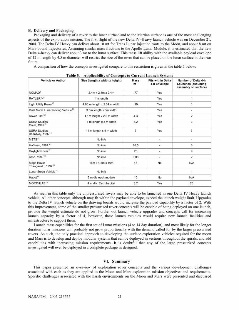
NASA/TM—2005-213555 21
B. Delivery and Packaging Packaging and delivery of a rover to the lunar surface and to the Martian surface is one of the most challenging
aspects of the exploration mission. The first flight of the new Delta IV–Heavy launch vehicle was on December 21, 2004. The Delta IV Heavy can deliver about 10 mt for Trans Lunar Injection routs to the Moon, and about 8 mt on Mars-bound trajectories. Assuming similar mass fractions to the Apollo Lunar Module, it is estimated that the new Delta 4-heavy can deliver about 3 mt to the lunar surface. This mass lift ability with the available payload envelope of 12 m length by 4.5 m diameter will restrict the size of the rover that can be placed on the lunar surface in the near future.
A comparison of how the concepts investigated compare to this restriction is given in the table 5 below:
Table 5.—Applicability of Concepts to Current Launch Systems Vehicle or Author Size (length x width x height) Mass
mT Fits within Delta
4-h Envelope Number of Delta 4-h Launches (assuming assembly on surface)
NOMAD8 2.4m x 2.4m x 2.4m .77 Yes 1
RATLER™9 1m length Yes 1
Light Utility Rover10 4.06 m length x 2.34 m width .99 Yes 1
Dual Mode Lunar Roving Vehicle11 3.5m length x 3m width Yes -
Rover First12 4.1m length x 2.6 m width 4.3 Yes 2
USRA Studies Creel, 199213
7 m length x 3 m width 6.2 Yes 3
USRA Studies Bhardwaj, 199214
11 m length x 4 m width 7 Yes 3
MSTS15 No info - -
Hoffman, 199716 No info 16.5 - 6
Daylight Rover17 No info 25 - 9
Arno, 199918 No info 6.08 - 2
Mega Rover Thangavelu, 199220
16m x 4.5m x 10m 45 No N/A
Lunar Sortie Vehicle21 No info - -
Habot22 5 m dia each module 10 No N/A
MORPHLAB23 4 m dia. Each habitat 3.7 Yes 26
As seen in this table only the unpressurized rovers may be able to be launched in one Delta IV Heavy launch
vehicle. All other concepts, although may fit within the payload envelope, exceed the launch weight limit. Upgrades to the Delta IV launch vehicle on the drawing boards would increase the payload capability by a factor of 2. With this improvement, some of the smaller pressurized rover concepts will be capable of being deployed on one launch, provide the weight estimate do not grow. Further out launch vehicle upgrades and concepts call for increasing launch capacity by a factor of 4, however, these launch vehicles would require new launch facilities and infrastructure to support them.
Launch mass capabilities for the first set of Lunar missions (4 to 14 day duration), and most likely for the longer duration lunar missions will probably not grow proportionally with the demand called for by the larger pressurized rovers. As such, the only practical approach to developing the surface exploration vehicles required for the moon and Mars is to develop and deploy modular systems that can be deployed in sections throughout the spirals, and add capabilities with increasing mission requirements. It is doubtful that any of the large pressurized concepts investigated will ever be deployed in a complete package as designed.
VI. Summary This paper presented an overview of exploration rover concepts and the various development challenges
associated with each as they are applied to the Moon and Mars exploration mission objectives and requirements. Specific challenges associated with the harsh environments on the Moon and Mars were presented and discussed
NASA/TM—2005-213555 22
along with challenges associated with proposed missions and delivery system. This paper also put forth a notional design strategy to effectively address critical requirements such as reliability and affordability. Specifically, efficient design cycle strategies were introduced and discussed along with strategies on developing a modular surface exploration design that can be deployed across all Lunar and Mars missions envisioned.
Based on all the information presented, modularity will be the single most important factor in the development of a truly viable surface mobility vehicle. To meet mission, reliability, and affordability requirements, surface exploration vehicles, especially pressurized rovers, will need to be modularly designed and deployed across all projected Moon and Mars exploration missions. The modular concept should start as unmanned teleoperated rovers, and grow into a variety of manned vehicles by upgrading and adding additional modules.
Additional conclusions based on the investigations and information presented herein are as follows:
• The new space exploration initiative will require more versatile, higher power rovers that are capable of highly reliable service over long duration missions.
• Novel design attributes inherent in some of the concepts reviewed may prove beneficial when considering future rover designs.
• Surface exploration vehicles for the lunar missions should be designed for the same life requirements as those required for the later Mars missions to minimize design uniqueness and properly verify concepts, hardware and systems well in advance of the Mars missions.
• Some basic technology development will be required to enable durable and highly reliable rover systems for long duration missions in harsh planetary environments.
References 1The Apollo Lunar Roving Vehicle http://nssdc.gsfc.nasa.gov/planetary/lunar/apollo_lrv.html 2Connors, Mary M.; Eppler, Dean B.; Morrow, Daniel G, “Interviews with the Apollo Lunar Surface Astronauts in Support
of Planning for EVA Systems Design,” NASA-TM-108846; September 1, 1994. 3Lunokhod 2 http://pages.preferred.com/~tedstryk/lunokhod2.html 4Lunokhod programme, Wikipedia, the free encyclopedia http://en.wikipedia.org/wiki/Lunokhod_program 5Lunakhod Spacecraft, spaceprojectsandinfo@aerospaceguide http://www.aerospaceguide.net/spacecraft/lunakhod.html 6Introduction to the Microrover, Jet Propulsion Laboratory, California Institute of Technology and the National Aeronautics
and Space Administration http://mars.jpl.nasa.gov/MPF/rovercom/rovintro.html 7Mars Exploration Rover Mission, NASA JPL web site
http://marsprogram.jpl.nasa.gov/mer/mission/spacecraft_rover_wheels.html 8E. Rollins, J. Luntz, A. Foessel, B. Shamah, and W.L. Whittaker, “Nomad: A Demonstration of the Transforming Chassis,”
Proceedings of the 1998 Intelligent Components for Vehicles, March 1998. 9Klarer, P.R., “Lunar exploration rover program developments,” SAND-93-1420C; CONF-9308159--2, SOAR 93: Space
Operations, Applications, and Research Conference, August 3–5, 1993. 10Thrasher, David L., “Piloted Rovers Study, Final Report,” D615-10019, Task 9.4, NAS8–37857, Boeing Advanced Civil
Space Systems, 1990. 11Abelson, Robert, et al. (2004) “Expanding Frontiers with Standard Radioisotope Power Systems,” JPL D-28902. 12Griffin, B., et al., (1992), “A Pressurized rover for Early Lunar Exploration,” AIAA–92–1488. 13Creel, Kenneth; Frampton, Jeffrey; Honaker, David; Mcclure, Kerry; Zeinali, Mazyar “Pressurized Lunar Rover,” NASA-
CR-192034; NAS 1.26:192034 , 19920501; May 1, 1992; 93N18015. 14Bhardwaj, Manoj; Bulsara, Vatsal; Kokan, David; Shariff, Shaun; Svarverud, Eric; Wirz, Richard, “Design of a Pressurized
Lunar Rover,” NASA-CR-192033; NAS 1.26:192033 , 19920424; Apr 24, 1992; 93N18016. 15Conceptual Design of a Mars Surface Transportation System (MSTS) http://www.lpi.usra.edu/lpi/HEDS-UP/texas.pdf 16Hoffman, Stephen J., and Kaplan, David I., “The Reference Mission of the NASA Mars Exploration Study Team,” NASA
SP-6107, 1997. 17Finley, Roland, “Pressurized Rover for Lunar Exploration, Daylight Rover Conceptual Design. Piloted rover technology
assessment study,” Task 5.9.4, NAS8–37857, Boeing Advanced Civil Space Systems, 1990. 18Arno, Rodger (1999) “Planetary Surface Vehicles” in Larson, Wiley J. and Pranke, Linda K., Eds., Human Spaceflight:
Mission Analysis and Design, New York: McGraw-Hill and Co., pp. 447–476. 19Cohen, Marc M. (2003) “Mobile Lunar and Planetary Bases,” AIAA–2003–6280, AIAA Space 2003 Conference, Long
Beach, CA, September 23–25, 2003, American Institute of Aeronautics and Astronautics. 20Thangavelu, Madhu, (1992) “The Nomad Explorer Assembly Assist Vehicle: An Architecture for Rapid Global Lunar
Infrastructure Establishment,” IAF-92-0743, 43rd IAF Conference. 21North American Rockwell, (1971, May 15). Lunar Base Synthesis Study: Final Report, SD 71-477-1 (Contract NAS8-
26145), Volume I, Executive Summary; Volume II, Mission Analysis and Lunar Base Synthesis.
NASA/TM—2005-213555 23
22Mankins, John C. (2000) “Modular Architecture Options for Lunar Exploration and Development,” IAA-00-IAA. 13.2.05, 51st International Astronautical Congress, October 2–6, 2000, Rio de Janeiro, Brazil.
23MORPHLAB: Modular Roving Planetary Habitat, Laboratory, and Base, University of Maryland, College Park, http://spacecraft.ssl.umd.edu/academics/484S04/morphlab_summary.pdf
24Bents, D.J., et al. (1991) SEI Power Source Alternatives for Rovers and Other Multi-kWe Distributed Surface Applications, Proceedings of the European Space Power Conference, September 2–6, 1991.
25Katzan, Cynthia M., Edwards, Jonathan L., “Lunar Dust Transport and Potential Interactions With Power System Components,” 1991, NASA Contractor Report 4404.
26Heiken, Grant H., Vaniman, David T., and French, Bevan M., “Lunar Sourcebook, A User's Guide to the Moon,” 1993, Cambridge University Press.
27Lunar Environmental Issues, Carnegie Mellon University Robotics Institute website http://www.frc.ri.cmu.edu/projects/lri/Luna/report/des_approach.html#REF61557
28Wilkinson, R. Allen, et al., “Granular Materials and the Risk They Pose for Success on the Moon and Mars.” 29Human Spaceflight: Mission Analysis and Design, Space Technology Series, Wiley J. Larson and Linda K. Pranke; Chapter
4, Surface Environments, Wendell Mendell, Jeffrey Plescia, and Alan C. Tribble. 30Lewicki, David G., Handschuh, Robert F., Heath, Gregory F., and Sheth, Vijay: “Evaluation of Carburized and Ground
Face Gears,” Journal of the American Helicopter Society, pp. 118–124, vol. 45, no. 2, April 2000. 31Nam Pry Suh, “Axiomatic Design, Advances and Applications,” Oxford University Press, New York, 2001. 32Genrich Altshuller, “The Innovation Algorithm,” Technical Innovation Center, Inc., Worcester, MA, 2000. 33Karen Tate, “Seven Management and Planning Tools,” Course Notes, GOAL/QPC, Methuen, MA. 34US Army Training and Doctrine Command, AD-A 166 390, 1985. 35Advanced Civil Space Systems, Piloted Rover Technology Study Task 9.1, NASA Contract NAS8–37857.

This publication is available from the NASA Center for AeroSpace Information, 301–621–0390.
REPORT DOCUMENTATION PAGE
2. REPORT DATE
19. SECURITY CLASSIFICATION OF ABSTRACT
18. SECURITY CLASSIFICATION OF THIS PAGE
Public reporting burden for this collection of information is estimated to average 1 hour per response, including the time for reviewing instructions, searching existing data sources,gathering and maintaining the data needed, and completing and reviewing the collection of information. Send comments regarding this burden estimate or any other aspect of thiscollection of information, including suggestions for reducing this burden, to Washington Headquarters Services, Directorate for Information Operations and Reports, 1215 JeffersonDavis Highway, Suite 1204, Arlington, VA 22202-4302, and to the Office of Management and Budget, Paperwork Reduction Project (0704-0188), Washington, DC 20503.
NSN 7540-01-280-5500 Standard Form 298 (Rev. 2-89)Prescribed by ANSI Std. Z39-18298-102
Form Approved
OMB No. 0704-0188
12b. DISTRIBUTION CODE
8. PERFORMING ORGANIZATION REPORT NUMBER
5. FUNDING NUMBERS
3. REPORT TYPE AND DATES COVERED
4. TITLE AND SUBTITLE
6. AUTHOR(S)
7. PERFORMING ORGANIZATION NAME(S) AND ADDRESS(ES)
11. SUPPLEMENTARY NOTES
12a. DISTRIBUTION/AVAILABILITY STATEMENT
13. ABSTRACT (Maximum 200 words)
14. SUBJECT TERMS
17. SECURITY CLASSIFICATION OF REPORT
16. PRICE CODE
15. NUMBER OF PAGES
20. LIMITATION OF ABSTRACT
Unclassified Unclassified
Technical Memorandum
Unclassified
National Aeronautics and Space AdministrationJohn H. Glenn Research Center at Lewis FieldCleveland, Ohio 44135–3191
1. AGENCY USE ONLY (Leave blank)
10. SPONSORING/MONITORING AGENCY REPORT NUMBER
9. SPONSORING/MONITORING AGENCY NAME(S) AND ADDRESS(ES)
National Aeronautics and Space AdministrationWashington, DC 20546–0001
Available electronically at http://gltrs.grc.nasa.gov
March 2005
NASA TM—2005-213555AIAA–2005–2525
E–14998
WBS–22–794–20–69
29
Exploration Rover Concepts and Development Challenges
James J. Zakrajsek, David B. McKissock, Jeffrey M. Woytach, June F. Zakrajsek,Fred B. Oswald, Kelly J. McEntire, Gerald M. Hill, Phillip Abel, Dennis J.Eichenberg, and Thomas W. Goodnight
Surface exploration vehicles; Lunar roving vehicles; Lunar mobile laboratories;Manned lunar surface vehicles; Mars roving vehicles
Unclassified -UnlimitedSubject Categories: 91 and 12
Prepared for the First Space Exploration Conference: Continuing the Voyage of Discovery sponsored by theAmerican Institute of Aeronautics and Astronautics, Orlando, Florida, January 30–February 1, 2005. Responsibleperson, James J. Zakrajsek, organization code RSM, 216–433–3968.
This paper presents an overview of exploration rover concepts and the various development challenges associated with each
as they are applied to exploration objectives and requirements for missions on the Moon and Mars. A variety of concepts for
surface exploration vehicles have been proposed since the initial development of the Apollo-era lunar rover. This paper
provides a brief description of the rover concepts, along with a comparison of their relative benefits and limitations. In
addition, this paper outlines, and investigates a number of critical development challenges that surface exploration vehicles
must address in order to successfully meet the exploration mission vision. These include: mission and environmental
challenges, design challenges, and production and delivery challenges. Mission and environmental challenges include
effects of terrain, extreme temperature differentials, dust issues, and radiation protection. Design methods are discussed that
focus on optimum methods for developing highly reliable, long-life and efficient systems. In addition, challenges associated
with delivering a surface exploration system is explored and discussed. Based on all the information presented, modularity
will be the single most important factor in the development of a truly viable surface mobility vehicle. To meet mission,
reliability, and affordability requirements, surface exploration vehicles, especially pressurized rovers, will need to be
modularly designed and deployed across all projected Moon and Mars exploration missions.