Embed Size (px)
Citation preview
NASA Contractor Report 187113
TROUBLE III: A Fault DiagnosticExpert System for Space Station
Freedom's Power System
David B. Manner
Sverdrup Technology Inc.
Lewis Research Center GroupBrook Park, Ohio
(NASA-CR-167IlJ} TROUBLE 3:
DIAGNOSTIC EXP_RT SYSTEM FOR
FREEDnM'3 POWER SYSTEM Findl
(Sw_r_ru_ Technology) 5k p
A FAULT
SPACE STATIWN
ReportCSCL IOB
GJlt_
N91-2422o
Unclas
0014938
Prepared forLewis Research Center
Under Contract NAS3-25266
N/ A
-x
https://ntrs.nasa.gov/search.jsp?R=19910014913 2020-04-26T09:41:18+00:00Z

TROUBLE II1:A FAULT DIAGNOSTIC EXPERT SYSTEM
FORSPACE STATION FREEDOM'S POWER SYSTEM
David B. Manner
Sverdrup Technology, Inc.NASA Lewis Research Center Group
Cleveland, OH 44135
ABSTRACT
Designing Space Station Freedom has given NASA many opportunities todevelop expert systems that automate onboard operations of space basedsystems. This thesis describes one such development, TROUBLE !11, anexpert system that has been designed to automate the fault diagnostics ofSpace Station Freedom's electric power system. TROUBLE IIl's design iscomplicated by the fact that Space Station Freedom's power system is stillevolving and changing. TROUBLE III had to be made flexible enough tohandle system changes with minimal changes to the program. Three typesof expert systems were studied: rule-based, set-covering and model-based.A set-covering approach was selected for TROUBLE III because it offered theneeded flexibility that was missing from the other approaches. With thisflexibility, TROUBLE III is not limited to Space Station Freedom applications,it can easily be adapted to handle any diagnostic system.
INTRODUCTION
As space based systems become larger and more technically advanced, theneed for automating the monitoring of these systems becomes moreapparent. Space Station Freedom has many areas where automation can beapplied that will reduce the number of personnel needed, increase reliabilityand speed up response time to faults. One method of automating systemmonitoring is to use expert systems.
This thesis describes TROUBLE II! which is a failure cause diagnostic expert
system designed to detect and diagnose failures that have occurred in SpaceStation Freedom's power system. TROUBLE ill is currently under
development at NASA Lewis Research Center. It was written using thecommercially available AI shell ART (Automated Reasoning Tool) fromInference Corporation and resides on a Texas Instruments Explorer IIworkstation.
Since September 1984, the design of the electric power system of SpaceStation Freedom has changed several times. Design issues include:
• Will generation be solely photovoltaic (DC) or will it be acombination of photovoltaic (DC) and solar dynamic (AC)?
• Will distribution be 20 KHZ 440V AC, 400 HZ 440V AC or 160VDC?
Since the design of the power system is still evolving and changing,TROUBLE III must be flexible enough to handle drastic design changes withminimal changes to the program.
To accomplish this flexibility, TROUBLE III uses a set-covering techniqueinstead of the traditional rule-based design. In set-covering, failureknowledge about the system is stored in a database instead of hard codedwit__hin_kt_h_et_ules.. TROU_B_LE_I_Ll's ru_!es__are u_ed tQ match_ the detectedsymptoms to this stored failure knowledge generating a list of failurehypotheses and the possible causes for each_ This list of failure hypothesesis then ranked according to which set of mode-cause pairs are most likelyresponsible for the observed condition of the system.
Failure knowledge is obtained by doing a Failure Mode and Effects Analysis(FMEA) on each component of the power system. Each unique failure mode- cause pair identified during the FMEA is stored as an object in the failureknowledge database. As Space StatiOn Freedom's power system evolvesand changes, the rule logic of TROUBLE III is unaffected with only the failureknowledge needing alteration.
TROUBLE III has been designed to handle fault diagnostics of an evolvingpower system. When Space Station Fre_0rfi's power system design isfinalized, TROUBLE ill will be quickly adapted to it. Thiswifla!!ow TROUBLEI1i to provide the autonomous monitoring of a power system needed by aspace-based system like Space Station Freedom.
DIAGNOSTIC EXPERT SYSTEMS
Many systems, especially electrical power systems, have human operatorsthat continuously monitor the system and diagnose the system's failures.
2
This task becomes increasingly difficult as the system becomes morecomplicated making the idea of automating diagnostics with expert systemshighly appealing. Expert systems are computer programs which emulate theknowledge and reasoning capabilities of a human expert. One requirementfor implementing a successful expert system is to have human expertsavailable who can solve the problems in their expertise domain. Sincehumans already have workable solutions for diagnostic tasks in areas suchas power systems, chemical processes and manufacturing systems, failurediagnosing large systems is an ideal application for expert systems.
Diagnostic expert systems accept quantitative measurements about thecurrent state of the system as inputs, change this data into qualitativeknowledge, determine if any failures exist and hypothesize the cause(s) forthose failures. The data acquisition task involves sampling rawmeasurements from appropriate equipment located throughout the systemand converting these measurements to appropriate engineering units.Quantitative state data alone carries no notion of whether or not the system
is performing within its tolerances. Knowing that a device has an output of115 volts is not very useful to the expert system. This type of data needs tobe compared to operating limits to obtain a qualitative statement like "deviceis operating above operating limits". This statement is more useful to theexpert system when it begins reasoning about the current state of thesystem. In its most rudimentary form, qualitative knowledge is a singlethreshold alarm - something is on or off. At a higher level, it allows forclassifying equipment operating performances as being abnormally low, withintolerance, abnormally high, etc. As abnormal operations are observed, anexpert system must be able to diagnose what events caused theseabnormalities. To do this, the expert system generates hypotheses about thecause of the malfunctions. There may be several hypotheses to explain asingle malfunction. Ideally, one wants to selectively generate hypotheses ina way that limits the number of hypotheses considered but, at the same time,will generate enough hypotheses to identify the most likely hypothesis is. Anexpert system can help the human operator(s) determine the probable causefor the detected failures by identifying all the possible causes for each failure.The goal of the diagnostic process is to generate a diagnosis which can"explain" all of the observations, especially the deviant ones.
Design Techniques
Design techniques used in diagnostic expert systems usually fall into one ofthree classifications: Rule-based systems, Model-based systems or Set-covering systems. Rule-based systems are the most common and are basedon experiential knowledge encoded in specific if-then rules. Model-basedsystems contain a simulation of expected behavior. System performance is
3
compared to expected performance to detect anomalies. Set-coveringsystems are based on the failure knowledge being pre-defined and stored ina database with general rules matching symptoms to failure data 11.
Rule-Based Systems
Rule-based systems are the best known and most widely used type of expertsystems. The knowledge of an expert in the problem domain is used todescribe possible malfunctions of the system and what conditions must existfor that malfunction to be present in the system. A series of if-then rules arethen developed that link the current system's conditions to the conditionsdescribed by the expert. Each possible fault or malfunction of the systemhas its own rule. If the right conditions exist, the rule concludes anappropriate failure cause.
All the failure knowledge about the system and the reasoning ability of theprogram is hard-coded into the rules. This makes rule-based systems verydomain specific. Seldom can they be generalized for use on a similarproblem. If the system or failure knowledge changes, the programmer mustchange all rules affected by these changes as well as adding new rules tocover any new situations.
Rule-based systems are said to contain shallow or experiential knowledgeabout how the system responds to certain conditions rather than deeperknowledge about how the system actually functions. Since rule-basedsystems are based on the knowledge of experts, their reasoning ability islimited in that they can only detect malfunctions that the experts are awareof. They cannot make inferences.
Model-Based Systems
In a model-based system the experts develop a system model which predictsthe expected behavior for the system and compare this to the actualbehavior. A fault is considered to be any discrepancy from the modeledbehavior. From the discrepancies between predicted and actual systembehavior, model-based programs can reason about where and whyanomalies occur.
To determine why something has Stopped working, it's Useful to know howit was supposed to work. Therefore, model-based systems containknowledge about the structure and behavior of the system and eachcomponent in the system. This knowledge enables the program to predictthe system's behavior under certain conditions and compare it to its actualbehavior.
4
Since the overall task of a model-based system is to use knowledge aboutthe component's structure and behavior to determine which componentscould have produced the anomalies, the following information is neededS:
1) measurements (observations) from the system
2) descriptions of the system's internal structure (includingconnections)
3) a description of the behavior of each component.
In model-based systems the large number of ways the system can fail isreduced to the number of ways in which each component type can fail - atechnically equivalent and more manageable approach. This technique isstrongly component INDEPENDENT. Given a design description of acomponent, work can begin on diagnosing the component before it is putinto a system. Since each component has its own model of how it operates,creating models for new systems is done by simply merging the individualcomponent models.
Set-Covering
A third type of diagnostic expert system is a set-covering system. A set-covering system is very similar to a rule-based system except that knowledgeabout the system's failure modes is stored in a database instead of beingencoded as rules. Set-covering is more dynamic and powerful than simplerule-based systems but, like rule-based systems, set-covering systems canonly recognize and react to system conditions that have been predefined byan expert.
In set-covering, once an abnormal operation has been detected, thesymptoms of the anomaly are matched against the predefined failure modesto come up with an ordered set of possible explanations. Therefore, it isimperative that knowledge of all failure modes of a system is available. Thisdiagnostic knowledge is a collection of known component failures, theirsymptoms, and possible causes for the failure.
A set of rules will look at the detected symptoms of the current state of thesystem and seek an explanation for them by linking all symptoms to thefailure and failure cause data that can best account for all the observations.
Every time a detected symptom matches the predefined symptom of one ofthe failures, a failure hypothesis is created which postulates a failure and itscause as a possible explanation for the observed abnormalities. Once all
5
hypotheses have been generated, the system determines which hypothesesare the most likely cause(s) for the abnormalities.
The Need for Expert Systems in Space:
As mentioned before, as systems become larger and more complex theybecome more and more difficult to monitor and diagnose. On Earth expertsystems are an appealing monitoring alternative or aid to human operators.Space is no exception. Technology is advancing and the size andcomplexity of the systems being put into space is growing. The need forautomated diagnostics is becoming apparent. For example, Skylab had an8KW power system that required 15 - 20 electrical power specialists forground support and a lot of valuable crew time to deal with faults. SpaceStation Freedom's power system, with its initial 75 KW power system, hasbecome so much larger and more technically advanced than Skylab that itwill require hundreds of ground support personal if not automated 12.
Expert systems offer a number of advantages for space bound projects. Asmentioned above, expert systems can reduce the number of airborne andground support personnel necessary for safe operation 6. This in turnreduces the cost of operating such projects as Space Station Freedom.Reducing the number of personnel aboard is a big advantage since the smallvolume of such space craft limits crew size. Therefore, crew time is veryvaluable and should not be used to monitor a system that an expert systemcould monitor.
, t- :]: 71 17 _ -- _ i:_:-i_-._Z-i 2-_ 771 7--:- : ::= :
Reliability is another advantfige expe_ sysiems offer space bound projects.In space it is imperative that the power system, life support systems, etc.remain operable. Therefore, reliable monitoring and diagnosing of thesesystems is a necessity. Unlike human operators, expert systems are always100% focused on their monitoring tasks. Expert systems do not getdistracted, bored or tired 3. They are always alert, operate 24 hours a day,and react faster than humans; ....
With the complexity and size of new space based systems and the limitednumber of available personnel it is appar#nt that there is a need forautomating the diagnosti c and monitoring processes in space. Expertsystems offer many advantages for space based system applications. Withtheir reliability, responsiveness, and the ability to reduce the number ofairborne and ground support personnel needed, expert systems caneffectively satisfy diagnostic automation needs in space.
6
Review of Existing Expert Systems
Expert systems have been developed for a broad range of applications. Inthe discussion that follows, only expert systems whose application falls intoone of the three domains related to TROUBLE III will be examined. Since
TROUBLE III is a diagnostic expert system for a space based power systemthese domains are: 1) power systems, 2) diagnostics systems and 3) spacebased systems.
Expert Systems for Power Systems
In the power domain, expert systems have been developed to handle faultdiagnostics, resource scheduling and contingency screening. Since powersystems' performances are fairly easy for experts to predict, they lendthemselves very nicely to the application of diagnostic expert systems. Adetailed discussion about diagnostic systems for _ based power systemsis deferred to section 2.3.3. What follows is a brief description of two
terrestrial power diagnostic systems: D2 and PERF-EXS.
D2, developed at Carnegie Mellon, is a distributed expert system for faultdiagnosis of a power system 2. D2 uses a set-covering model written inOPS5 to generate all the credible hypotheses that explain a given set ofdetected alarms. It runs on three microVAXes in an environment developed
to allow it to run in parallel.
D2 is broken down into three members: the manager, proposal crew andconstruction crew. The manager uses set-covering for alarm processing.The proposal crew conjectures events to expand incomplete hypothesesfound by the manager. The construction crew then takes these conjecturesand translates them into actual events.
PERF-EXS is a diagnostic expert system based for performance evaluation ofa power plant 4. It was developed jointly by the companies APEIRON andANSALDO and was aimed at capturing ANSALDO'S vast knowledge andexpertise in power plants. Most diagnostic expert systems use a custombuilt expert system shell. PERF-EXS instead makes use of a generalpurpose, commercially available shell named KEE (Knowledge EngineeringEnvironment).
PERF-EXS is broken down into two components: fault detection and faultmodels. These two components work together to detect malfunctions, startthe diagnostics, and locate the cause(s) of the malfunction. The physicalpower plant is divided into the following subsystems: boiler, turbogenerator,condenser, electrical auxiliaries and water regeneration. The diagnostic
7
expert system monitors the performance of each subsystem and integratesinformation from all of them to correctly diagnose malfunctions.
In the detection phase, PERF-EXS receives information about measuredvariables and depends only on those readings to detect malfunctions. In thediagnostic phase, the general inference engine reasons on the failureknowledge base, searches for the cause(s) of the malfunctions detected, andsuggest ways to correct them.
PERF-EXS is very similar to TROUBEE III. Both rely on measurementreadings to detect the system--ssymptoms. Both_v_e the power system upinto independent subsystems and both US-e-a-commercia.lly-avaiiableshell.The main difference is that PERF-EXS uses a mode-basedapproach whileTROUBLE III uses set-covering.
Resource scheduling for a power plant on Earth is not a major concern. Ifevery user on the system wants to operate at the same time, the power plantsimply generates more electricity or buys it from other plants on the systemgrid to satisfy the peak electricity need. But in space, there is a maximumamount of electricity that can be produced and many more users than canbe supplied at once. Therefore, the system has to schedule resources toensure tiiat every user gets th-e eiectr]c]ty it needs at Some time while neveroverloading the system. Since this problem only occurs in space powersystems, the discussion of these expert systems is deferred to section 2.3.3.
Contingency screening is the last power system area that will be discussed.It is very important for the power industry to be able to predict theconsequences of disturbances and take measures to prevent deterioration inservice quality.
Case Western Reserve University along with Cleveland Electric Iiluminatinghave developed a rule-based expert system with knowledge of the powersystem that uses pattern recognition techniques to do contingencyscreening 17. This program has been demonstrated on moderate size powersystems.
Non-power Related Diagnostic Expert Systems
In this section, diagnostic expert systems will be discussed that arecompetent in domains other than electric power. These are typical ofdiagnostic systems that have been successfully developed for many diverseapplications.
The most famous diagnostic expert system is MYCIN 19,a medical diagnostic
8
program which queries a patient like a doctor to diagnose the patient'sillness. The program reasons on the symptoms the patient has entered.When it comes to a fork in the decision tree, it asks for more information tohelp decide which path to follow until it finally reaches a conclusion on thepatient's health.
EDNACS (Expert Diagnostics for Nitric Acid Cooling System) is an exampleof a diagnostic expert system developed for a chemical processing plant 16.EDNACS was developed at the University of Waterloo to regulate thetemperature of nitric acid in a chemical cooling system. EDNAC is dividedinto 4 stages: sensory, fault detection, anticipation and prevention. Thesensory stage observes the status of objects and reports abnormalconditions to the fault detection stage. The fault detection stage uses rulesto determine what fault(s) corresponds to abnormal conditions. Anticipationstate predicts the future consequences of the fault while the prevention stagesuggests actions that may prevent future failures.
MYCIN and EDNACS are only two of the many diagnostic expert systemsthat have been developed. But they show how diverse the applications canbe. There is no limit to where diagnostic expert systems can be applied and
power system diagnostics, like TROUBLE III, are just a small part of thatdomain.
Space Based Expert Systems
Several areas are currently being explored to assess the benefits of applyingexpert systems to space based systems. Power system diagnostics,resource scheduling, potable water systems, and data reduction are just afew areas where expert systems are being investigated.
NASA is committed to automating Space Station Freedom. Both the LewisResearch Center and the Marshall Space Flight Center have automation labsthat are currently developing diagnostic expert systems for Space StationFreedom. Lewis' developments include TROUBLE III and APEX whileMarshall is developing STARR, AMPERES, and ADEPT.
APEX (Autonomous Power Expert System) was developed using KEE andLISP on a Texas Instruments Explorer II workstation 9. It is a rule-basedsystem that performs fault diagnostics on the 20kHz switchgear. APEX isable to detect static faults in the switchgear as well as incipient failures (ie.insulation breakdown in transformers, contact depletion in mechanicalswitches, and thermal conductivity degradation in power semiconductors).
STARR was built on a Xerox 1109 workstation using KEE 2°. It is a rule-
9
based system that monitors a space power system, recognizes problemstates, identifies the failure and recommends proper actions. Eachcomponent of the test bed has a corresponding object in STARR. Theprogram monitors the test bed and looks for symptoms, then generates faulthypotheses. In normal operation, STARR gets updated information abouteach component approximately once per minute.
STARR was used as the prototype for AMPERES (Autonomously ManagedPower system Extendable Real-time Expert System)13. AMPERES uses a"component centered" approach which encompasses the strength of amodel-based approach. It, like STARR, is a rule-based system that iscomposed of the following functional models: main controller, status monitor,fault diagnosing, knowledge base and interface handler. Each component ofthe test bed has a corresponding object in AMPERES. Once symptoms aredetected, fault rules are run to find the faults and give a cause andrecommended action.
ADEPT (Automatic Detection of Electric Power Troubles) is yet anotherdiagnostic expert system created by Marshall for fault isolation on a powersystem2121. ADEPT is implemented in LISP on a symbolic 3670. It usesOhm's law as a basis for the rules that isolate the faults. ADEPT looks forsignificant changes at any sensor point then flags that fault condition andsends it off for fault rule analysis.
STARR, AMPERES and ADEPT encode their failure cause diagnosticknowledge in rures which makes them difficult to adapt to a new system.With Space Station Freedom's power system still evolving, frequent revisionsneed to be made to theseexpert systems to make their rules appropriate forSpace Station Freedom. This is where TROUBLE III, with its flexible set-covering approach, has superior flexibility over other diagnostic expertsystems.
Resource allocation is a major problem aboard Space Station Freedom. Forthe power system, allocating this limited resource so that station productivityis maximized without overloading the system would be a difficult task for ahuman operator to do quickly. Power allocation and scheduling need to beautomated and expert systems are a prime candidate. NASA Marshal isinvestigating two schedulers on their test beds.
LES (Load Enable scheduler) is coded in Lisp and runs on a LISP22
workstation . lt_e_Uies §nd resch_d_J_the payioads ufor Space StationFreedom and is capable of handling hundreds of scheduling constraints.
LPLMS (Loads Priority List Management System) is also implemented in LISP
10
on a LISP workstation_. It continuously computes a priority list of thecurrent users so in case of faults or loss or power, it can tell the systemwhich loads to shed first to avoid shutting down the whole power system.
Two other applications of expert systems technology in space systems arefor space station's potable water system and for Hubble telescope's datareduction. The Application Generator1 is a fault diagnostic system analyzesfailures which have occurred on the system that reclaims potable water fromwaste water. I-DARE_ is an expert system that performs data reduction ofthe telemetry stream from the Hubble telescope.
SPACE STATION FREEDOM'S POWER SYSTEM
NASA has been engaged in the definition and design of Space StationFreedom since 1984. The design for the electrical power system has yieldedtwo major requirements: 1) deliver 87.5 kW continuous electrical power and2) deliver 113.5 kW peak power for up to 15 minutes during each orbit 18.
Deciding what type of generation and distribution to use are the two maindesign issues for Freedom's Electrical Power System (EPS). The threepossible designs for generating the electrical power are an all photovoltaic(PV) system, all solar dynamic (SD) system or a hybrid (PV and SD) system.The options considered for distributing the electricity are a 20 kHz 440v ACsystem, a 400 Hz 440v AC system, and a 120v DC system. The followingsection describes Space Station Freedom power system's design evolution.
Chronology of Distribution System
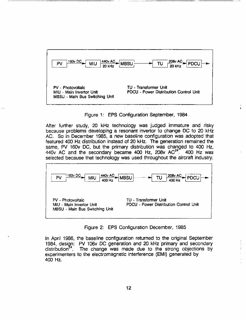
In September 1984, the baseline configuration for Space Station Freedom'selectrical power system consisted of photovoltaic generation and 20 kHz ACdistribution. PV arrays generated 160v DC which was sent to the maininvertor unit to be transformed to the primary distribution of 20 kHz, 440v AC.The primary distribution was then stepped down to 20 kHz, 208v AC for thesecondary distribution to the loads 24. This configuration made use of themature PV technology but introduced 20 kHz - a new technology.
11
160vDC_M-_I 20 kHz --I I
PV - PhotovoltaicMIU - Main Invertor UnitMBSU - Main Bus Switching Unit
TU - Transformer UnitPDCU - Power Distribution Control Unit
Figure 1" EPS Configuration September, 1984
After further study, 20 kHz technology was judged immature and riskybecause problems developing a resonant invertor to change DC to 20 kHzAC. So in December 1985, a new baseline configuration was adopted thatfeatured 400 Hz distribution instead of 20 kHz. The generation remained thesame, PV 160v DC, but the primary distribution was changed to 400 Hz,440v AC and the secondary became 400 Hz, 208v AC 24. 400 Hz wasselected because that technology was used throughout the aircraft industry.
__r--_---] 20avACJEk-;;T!__._--i ,v _400Hz rtru_uJ v
PV - PhotovoltaicMIU - Main Invertor UnitMBSU - Main Bus Switching Unit
TU - Transformer UnitPDCU - Power Distribution Control Unit
Figure 2: EPS Configuration December, 1985
In April 1986, the baseline configuration returned to the original September1984, desiqn: PV 106v DC generation and 20 kHz primary and secondarydistribution TM. The change was made due to the strong objections byexperimenters to the electromagnetic interference (EMI) generated by400 Hz,
12
--_'_ 160v DC_ 440v AC=_ _ 208v AC=_20kHz--_'_ ,u 120kHz v[ru_'uJ v
PV - Photovoltaic
MIU - Main Invertor Unit
MBSU - Main Bus Switching Unit
TU - Transformer UnitPDCU - Power Distribution Control Unit
Figure 3: EPS Configuration April, 1986
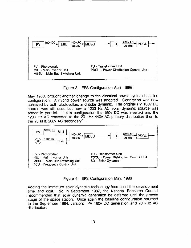
May 1986, brought another change to the electrical power system baselineconfiguration. A hybrid power source was adopted. Generation was nowachieved by both photovoltaic and solar dynamic. The original PV 160v DCsource was still used but now a 1200 Hz AC solar dynamic source wasadded in parallel. In this configuration the 160v DC was inverted and the1200 Hz AC converted to the 20 kHz 440v AC primary distribution then tothe 20 kHz 208v AC secondary 21.
_ov AC
(_ 1200 Hz_-_ 20 kHz --_
_t_-0---] 208vAC=_20 kHz _I ru_u I
PV - PhotovoltaicMIU - Main Invertor UnitMBSU - Main Bus Switching Unit
FCU - Frequency Control Unit
TU - Transformer UnitPDCU - Power Distribution Control Unit
SD - Solar Dynamic
Figure 4: EPS Configuration May, 1986
Adding the immature solar dynamic technology increased the developmenttime and cost. So in September 1987, the National Research Councilrecommended that solar dynamic generation be deferred until the growthstage of the space station. Once again the baseline configuration returnedto the September 1984, version: PV 160v DC generation and 20 kHz ACdistribution.
13
_1160v DC_ 440v AC-_20 kHz T[ _lD°ul lm,-
PV - PhotovoltaicMIU - Main Invertor Unit
MBSU - Main Bus Switching Unit
TU - Transformer Unit
PDCU - Power Distribution Control Unit
Figure 5: EPS Configuration September, 1987
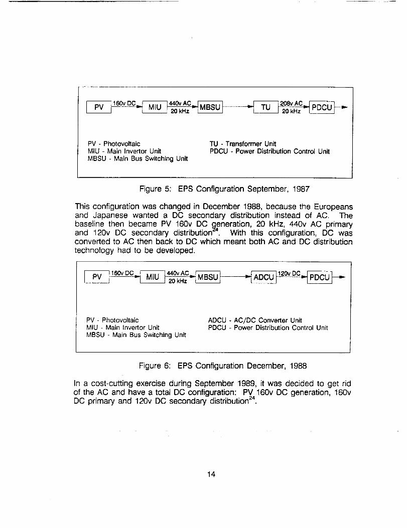
This configuration was changed in December 1988, because the Europeansand Japanese wanted a DC secondary distribution instead of AC. Thebaseline then became PV 160v DC generation, 20 kHz, 440v AC primaryand 120v DC secondary distribution _4. With this configuration, DC wasconverted to AC then back to DC which meant both AC and DC distributiontechnology had to be developed.
-_ 160v DC__
PV- PhotovoltaicMIU - Main Invertor Unit
MBSU - Main Bus Switching Unit
ADCU - AC/DC Converter UnitPDCU - Power Distribution Control Unit
Figure 6: EPS Configuration December, 1988
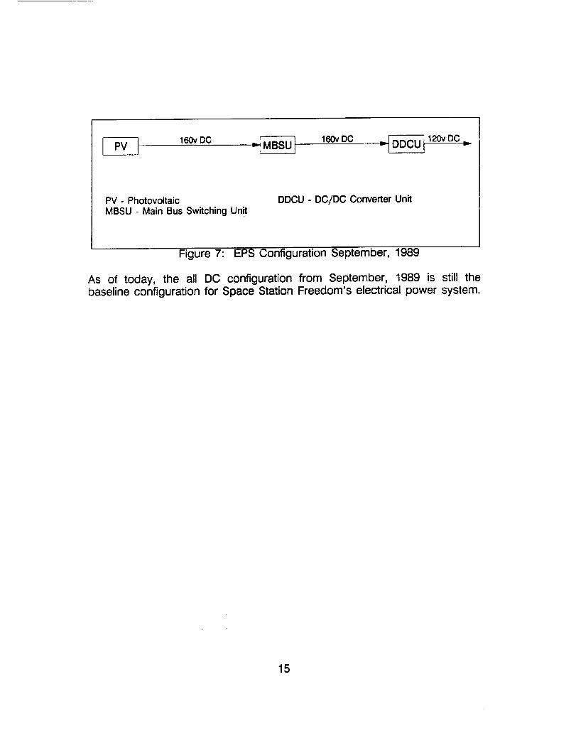
In a cost-cutting exercise during September 1989, it was decided to get ridof the AC and have a total DC configuration: PV 160v DC generation, 160vDC primary and 120v DC secondary distribution 24.
14
160vDC MBSU] 160v oC __ 120v DC
PV - PhotovoltaicMBSU - Main Bus Switching Unit
DDCU - DC/DC Converter Unit
Figure 7: EPS Configuration September, 1989
As of today, the all DC configuration from September, 1989 is still thebaseline configuration for Space Station Freedom's electrical power system.
15
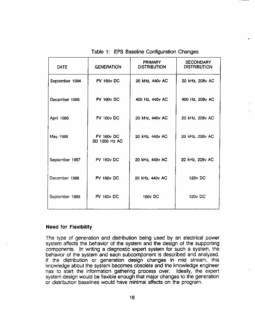
Table 1: EPS Baseline Configuration Changes
DATE
September 1984
December 1985
April 1986
May 1986
September 1987
December 1988
GENERATION
PV 160v DC
PV 160v DC
PV 160v DC
PV 160v DCSD 1200 Hz AC
PV 160v DC
PV 160v DC
PRIMARY
DISTRIBUTION
20kHz, 440vAC
400 Hz, 440v AC
20 kHz, 440v AC
20 kHz, 440v AC
20 kHz, 440v AC
20 kHz, 440v AC
September 1989 PV 160v DO 160v DC
SECONDARYDISTRIBUTION
20 kHz, 208vAC
400 Hz, 208v AC
20 kHz, 208v AC
20 kHz, 208v AC
20 kHz, 208v AC
120v DC
120v DC
Need for Flexibility
The type of generation and distribution being used by an electrical powersystem affects the behavior of the system and the design of the supportingcomponents. In writing a diagnostic expert system for such a system, thebehavior of the system and each subcomponent is described and analyzed.If the distribution or generation design changes in mid stream, thisknowledge about the system becomes obsolete and the knowledge engineerhas to start the information gathering process over. Ideally, the expertsystem design would be flexible enough that major changes to the generationor distribution baselines would have minimal affects on the program.
16
Since 1984, the generation and distribution baseline configuration for SpaceStation Freedom has changed six times. Any diagnostic expert systemapplied to this system should be flexible so it can handle these major designchanges if any more should come along. TROUBLE III was designed withthis type of flexibility and is discussed in the next chapter.
TROUBLE III
Background
Automating the operation of Space Station Freedom's electric power systemis rife with technologic opportunities. Expert Systems will be used toschedule power resources as well as monitor and diagnose faults on thepower system 8. TROUBLE III, a diagnostic expert system, has been createdto perform fault detection and isolation for the electrical power system ofSpace Station Freedom.
TROUBLE III is one of the projects of the Power System Facility AdvancedAutomation Lab located at NASA Lewis Research Center. It is an object-
oriented program developed using the commercially available AI shell, ART(Automated Reasoning Tool) from Inference Corporation. ART is a LISPbased shell and is installed on a Texas Instruments Explorer II workstation.
Space Station Freedom's electric power system design is still changing. Thiscomplicates designing an expert diagnostic system since there is nooperating or failure experience. Usually, expert systems are built for workingsystems for which there are knowledgeable experts. In these cases, thedesign and specifications are an a priori knowledge base upon which theknowledge engineer builds. What measurements are needed, how eachcomponent of the system interacts with other components, and what faultsare most likely to occur in given situations are already known to the expertand establishes a good frame work upon which to build a diagnostic
program.
Space Station Freedom is different. Without exact design and performanceinformation and with no operating experience it is hard to identify abnormalbehavior let alone write an expert system to do it. What is needed is aflexible expert system that can quickly accommodate a design change.Therefore, TROUBLE III has been designed using set-covering to representfailure knowledge, rather than rules or models, to give it the flexibility neededto handle the design changes in the power system.
17
Design
The objective of TROUBLE Iil is to apply expert system technologies todevelop an automated system for detecting and diagnosing failures andfailure causes for the electric power system of Space Station Freedom.TROUBLE !11 is an object-oriented program which performs the followingtasks:
. Symptom DetectionMonitors measurements throughout the system and determines whatfailure symptoms, if any, are present. _-"
. Reasoned Assumptions --Rules examine the current state of the system and decide whethereach potential failure object should have a reason for inclusion orexclusion when it is matched to the detected symptoms. If the failurehypothesis is to be excluded then no further processing is done.
. Failure Hypothesis GenerationDetected symptoms are matched to the predefined failure data tocome up with the possible failure hypotheses.
. Subcause Generation
The FHRs are linked together to form chains. The chains start withthe last failure of a chain reaction and work backwards to a rootcause. For each root cause, there is a separate chain. Chains takethe form "A failed because of B, B failed because of C; therefore C isa root cause of A". Once the chains are formed, they are ranked inorder of their ability to explain the observed abnormalities.
. Explanation and JustificationThe Justification Module takes any of the chains and justifies to theuser why the cause of that chain was selected as a possible rootcause for that failure.
° Human Interactions
The Output Module displays the requested results to the user. Thismodule can show the detected symptoms, the top level failures andpossible root causes (ranked in order of most probable) or thejustification for one of the chains. An Input Module allows the user toload a test file or manually change the value of any of themeasurement devices for the purpose of testing.
18
TECHNIQUES USED BY TROUBLE III
TROUBLE
lll
FMEA
(failure modesand effects
ana_is)
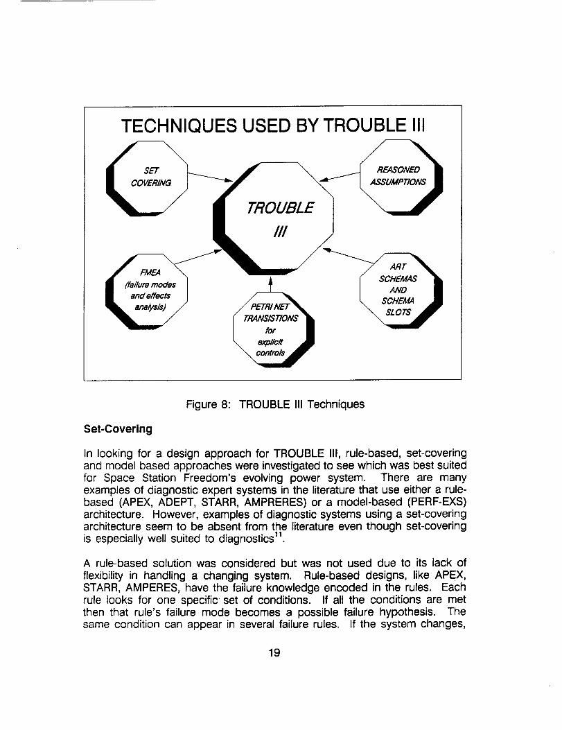
Figure 8: TROUBLE III Techniques
Set-Covering
In looking for a design approach for TROUBLE III, rule-based, set-coveringand model based approaches were investigated to see which was best suitedfor Space Station Freedom's evolving power system. There are manyexamples of diagnostic expert systems in the literature that use either a rule-based (APEX, ADEPT, STARR, AMPRERES) or a model-based (PERF-EXS)architecture. However, examples of diagnostic systems using a set-coveringarchitecture seem to be absent from the literature even though set-coveringis especially well suited to diagnostics 11.
A rule-based solution was considered but was not used due to its lack of
flexibility in handling a changing system. Rule-based designs, like APEX,STARR, AMPERES, have the failure knowledge encoded in the rules. Eachrule looks for one specific set of conditions. If all the conditions are metthen that rule's failure mode becomes a possible failure hypothesis. Thesame condition can appear in several failure rules. If the system changes,
19
as is the case with Space Station Freedom, the programmer must gothrough the complicated interconnections of the rules and change theconditions and resulting failures to correspond to the new design. Thismakes rule-based design very domain specific and not a good choice to beused with Space Station Freedom's dynamic evolving power system.
Davis and Hamschers make a good argument for the use of a model-basedarchitecture. Unfortunately, model-based systems are best suited for anexisting system since knowledge about the internal structure of eachcomponent, the connections of each component and behavioral descriptionof each component is needed. With Freedom's power system still changingthis information is not available. Making a good model of the system isalready a difficult task, but adding the complexity of modeling an evolvingsystem makes a model-based architecture unattractive for Space StationFreedom.
In set-covering, knowledge about the failures is stored as data with the rulesbeing independent of this failure knowledge. With this technique, variabledata (symptoms) is compared to variable date (failure modes). This givesthe expert system the flexibility to adept to changes in the system withouthaving to rewrite rules.
With flexibility being the key in selecting an architecture for TROUBLE III, aset-covering approach was selected. With this architecture, updating thefailure knowledge database is the only change needed to adapt TROUBLEIII to the new design.
Transitions
A production system's architecture employs a set of rules, a global databaseand an inference engine that performs the recognize-act cycle of match,conflict resolution and rule-firing 23. TROUBLE III is not strictly a rule-basedsystem but does perform the recognize-act cycle. Therefore, TROUBLE IIIis not a pure production system according to the definition but since itbehaves like one, it will be considered a production system in this discussion.
In a pure production system, rules are in a sequential list and are evaluatedone at a time according to the order of the list. When all the conditions ofa rule are found true, the rule is executed and the rule evaluation beginsagain at the top of the rule list. Most large production systems, includingTROUBLE III, can be divided into sub-systems (modules) that perform welldefined tasks. If the programmer exerts control over when each sub-system's rules fire, the sub-systems will behave like sub-routines or functionsin procedural code.
2O
Explicit control over the flow of the program is advantageous to a productionsystem that is modularized. Since a production system evaluates the entirelist of sequential rules, the more rules there are the slower the execution is.Therefore, the production system will run faster if the set of rules it isevaluating is only a subset of the whole set of rules. Also, many timescertain tasks need to be performed before others. In a pure productionsystem where all rules are eligible for execution all the time, implementing"rule priority" correctly becomes difficult. Where as having explicit controlover the rules makes rule prioritization a simple task. Therefore, for efficiencyand correctness a structure is needed that adds explicit control to productionsystems.
Zisman23encountered this problem in his work with asynchronous concurrentproduction systems for independent event driven office procedures. Zismansuggested that Petri net transitions be used to model the interaction andtemporal relationships between the asynchronous concurrent events.
TROUBLE III is not a pure asynchronous concurrent production system likeZisman's office procedure but it does have the same need for explicit controlover rule-firing. TROUBLE III expands Zisman's work to a non-asynchronousconcurrent production systems. Like Zisman, TROUBLE III uses Petri netsto dynamically extract from the set of system rules those rules which arerelevant given the present system state. Transitions represent a process ortask; since these processes are described by productions (rules)., thetransition is really a "home" for the set of rules describing the process23.
Transitions control which set of rules are active in TROUBLE II1. Eachmodule has its own transition object which appears as one of the conditionsin each rule in the module. Transitions have the value inactive, active, orfired. Petri nets, in the form of rules, control the status of each transitions.If all the conditions are satisfied for a transition's rule, that transition becomesactive, otherwise it remains inactive. More than one transition can be activeat a time but only one can be fired. Conflict rules are used to resolve theconflict of which transition to fire when multiple transitions are active. If onlyone is active, it immediately fires. All rules associated with a fired transitionconstitute the active rule set. TROUBLE IIl's inference engine continually
cycles through the active rule set evaluating its rules. Only rules in the activerule set are evaluated. As transitions are fired and become inactive, the
active rule set changes.
TROUBLE 3 expanded Zisman's work to include nesting of transitions. InTROUBLE IIl's design, rule prioritization was needed inside some of themodules. To handle this, new sets of transitions were implemented inside of
21
modules thus creating a nested Petri net transition structure.
By using Petri net transition, TROUBLE III was able to break its design intomodules and have explicit control over rule-firing. This reduced the numberof active rules which in turn reduces the processing time.
Failure Modes and Effects Analysis
The failure knowledge database can be obtained by performing a failuremodes and effects analysis (FMEA) of the system to be diagnosed. FMEAis a method of identifying possible system failures and their consequences.
In a FMEA, an expert on the system describes the ways each systemcomponent can fail. Each of these failures is called a failure mode and is aqualitative description of the failure. For example, "No discharge current"would be one of the possible failure modes for a battery charge dischargeunit (BCDU).
The expert then describes all possible causes for each failure mode. "Nocharge on Battery" is an example of one of the possible causes for theBCDU failure mode "No discharge current". Each unique failure-mode-causepair in the FMEA is used as a separate failure object in the failure database.The symptom that a failure mode manifests is also identified in the FMEA.It too is stored in the failure database.
The FMEA is complete when all of the failure modes, causes and symptomshave been described for each system component. All this informationcollectively represents the known failure knowledge of the system. Once thisinformation is entered into the database it is used by the failure rules togenerate the failure hypothesis.
Detection Module
To detect failures TROUBLE III searches for evidence of possible failures(symptoms) using measurements taken throughout the power system. Eachmeasurement has its own unique data object. This object contains manycharacteristics such as: the unique name of the device, the type of deyice(voltmeter, ammeter etc.), the measuring unit, the present measurementvalue, the device's purpose and its location. These attributes are defined inadvance and do not change, with the exception of the measurement value.During each sampling period, each measurement's value slot is updated toreflect the most current information about the system's state.
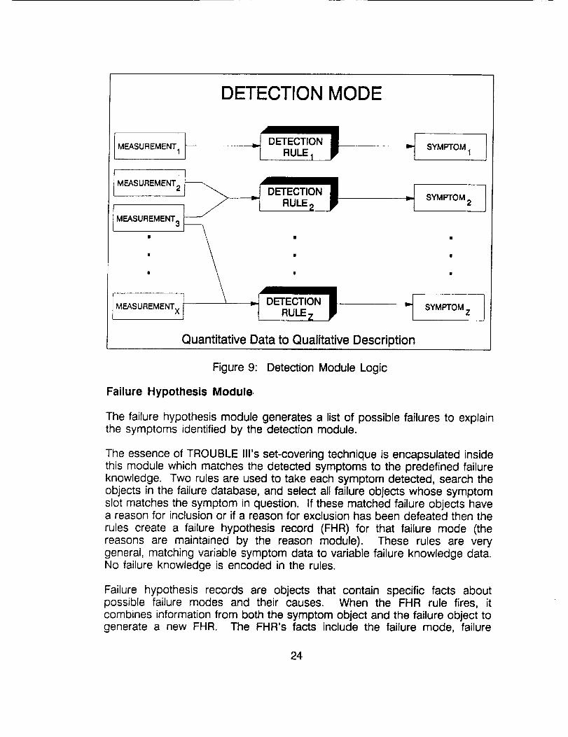
The detection module converts the quantitative measurements into qualitative
22
symptoms that describe the system's performance. Detection rules monitorthe measurements and look for predefined symptoms of abnormal behavior.During the FMEA process, a symptom associated with each failure mode wasdescribed. Each symptom has a detection rule. If the measurement object'sattributes satisfy all the conditions of the rule, then the rule asserts thecorresponding symptom to the system. If the conditions are not satisfied,then the symptom does not exist and cannot be reasoned about by the restof the program. The detected symptoms give a qualitative description of thecurrent state of the system.
Each symptom is itself a data object. The information stored about eachsymptom includes: its unique name, its description of the symptom (i.e. lowoutput), its list of measurement devices used, its location of the measurementdevice, and a time stamp to tell when the symptom was detected.
The power system is broken down into many subsystems and componentseach with its own measurement devices and detection rules. Sincemeasurements in one subsystem may be used by a detection rule in another,all measurement objects are stored in one file. The detection rules aregrouped according to subsystem or component and stored in their own file.In this way a maintenance programmer can quickly and easily find the codethat needs to be changed.
Once the system's measurements have been read in and the failuresymptoms have been detected, a list of possible failures for the detectedsymptom(s) is generated by the Failure Hypothesis Module.
23
DETECTION MODE
MEASUREMENT 1
MEASUREMENT 2
MEASUREMENT 3
SYMPTOM 1 j
RULE2 P .7 SYMPTOM2
Quantitative Data to Qualitative Description
Figure 9: Detection Module Logic
Failure Hypothesis Module,
The failure hypothesis module generates a list of possible failures to explainthe symptoms identified by the detection module.
The essence of TROUBLE IIl's set-covering technique is encapsulated insidethis module which matches the detected symptoms to the predefined failureknowledge. Two rules are used to take each symptom detected, search theobjects in the failure database, and select all failure objects whose symptomslot matches the symptom in question. If these matched failure objects havea reason for inclusion or if a reason for exclusion has been defeated then therules create a failure hypothesis record (FHR) for that failure mode (thereasons are maintained by the reason module). These rules are verygeneral, matching variable symptom data to variable failure knowledge data.No failure knowledge is encoded in the rules.
Failure hypothesis records are objects that contain specific facts aboutpossible failure modes and their causes. When the FHR rule fires, itcombines information from both the symptom object and the failure object togenerate a new FHR. The FHR's facts include the failure mode, failure
24
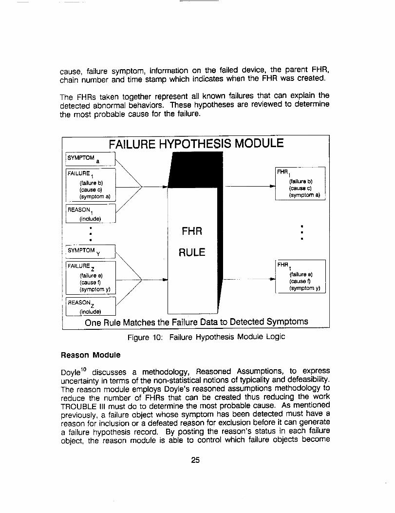
cause, failure symptom, information on the failed device, the parent FHR,chain number and time stamp which indicates when the FHR was created.
The FHRs taken together represent all known failures that can explain thedetected abnormal behaviors. These hypotheses are reviewed to determinethe most probable cause for the failure.
SYMPTOMa
FAILURE1
(failure b)(causec)(symptom a)
REASON 1
(include)
SYMPTOM y
FAILURE Z
(failure e)(causef)(symptom y)
i REASON Z(include)
FAILURE HYPOTHESIS MODULE
FHR i
(failure b)
(causec)(symptom a)
\\
\
FHR
RULE
FHR t
._ (failure e)
(causef)(symptom y)
One Rule Matches the Failure Data to Detected Symptoms
Figure 10: Failure Hypothesis Module Logic
Reason Module
Doyle 1° discusses a methodology, Reasoned Assumptions, to expressuncertainty in terms of the non-statistical notions of typicality and defeasibility.The reason module employs Doyle's reasoned assumptions methodology toreduce the number of FHRs that can be created thus reducing the workTROUBLE III must do to determine the most probable cause. As mentioned
previously, a failure object whose symptom has been detected must have areason for inclusion or a defeated reason for exclusion before it can generate
a failure hypothesis record. By posting the reason's status in each failureobject, the reason module is able to control which failure objects become
25
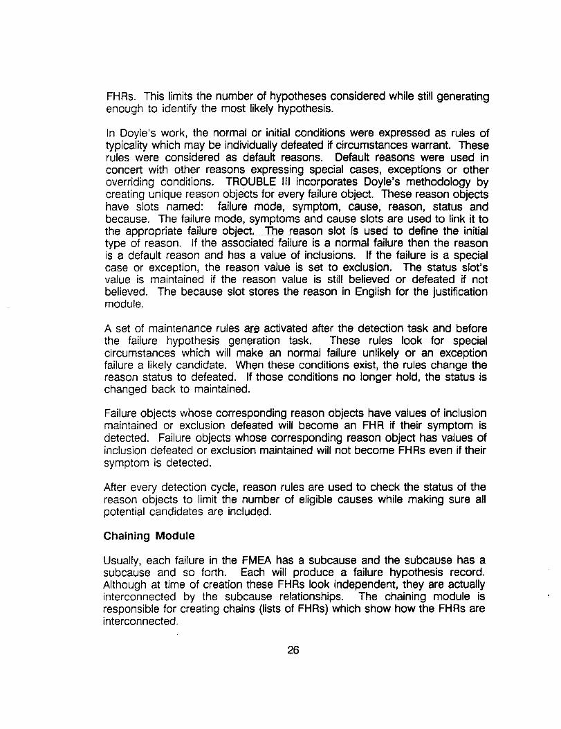
FHRs. This limits the number of hypotheses considered while still generatingenough to identify the most likely hypothesis.
In Doyle's work, the normal or initial conditions were expressed as rules oftypicality which may be individually defeated if circumstances warrant. Theserules were considered as default reasons. Default reasons were used in
concert with other reasons expressing special cases, exceptions or otheroverriding conditions. TROUBLE III incorporates Doyle's methodology bycreating unique reason objects for every failure object. These reason objectshave slots named: failure mode, symptom, cause, reason, status andbecause. The failure mode, symptoms and cause slots are used to link it tothe appropriate failure object. The reason slot is used to define the initialtype of reason, if the associated failure is a normal failure then the reasonis a default reason and has a value of inclusions. If the failure is a specialcase or exception, the reason value is set to exclusion. The status slot'svalue is maintained if the reason value is still believed or defeated if not
believed. The because slot stores the reason in English for the justificationmodule.
A set of maintenance rules are activated after the detection task and before
the failure hypothesis generation task. These rules look for specialcircumstances which will make an normal failure unlikely or an exceptionfailure a likely candidate. When these conditions exist, the rules change thereason status to defeated. If those conditions no longer hold, the status ischanged back to maintained.
Failure objects whose corresponding reason objects have values of inclusionmaintained or exclusion defeated will become an FHR if their symptom isdetected. Failure objects whose corresponding reason object has values ofinclusion defeated or exclusion maintained will not become FHRs even if their
symptom is detected.
After every detection cycle, reason rules are used to check the status of thereason objects to limit the number of eligible causes while making sure allpotential candidates are included.
Chaining Module
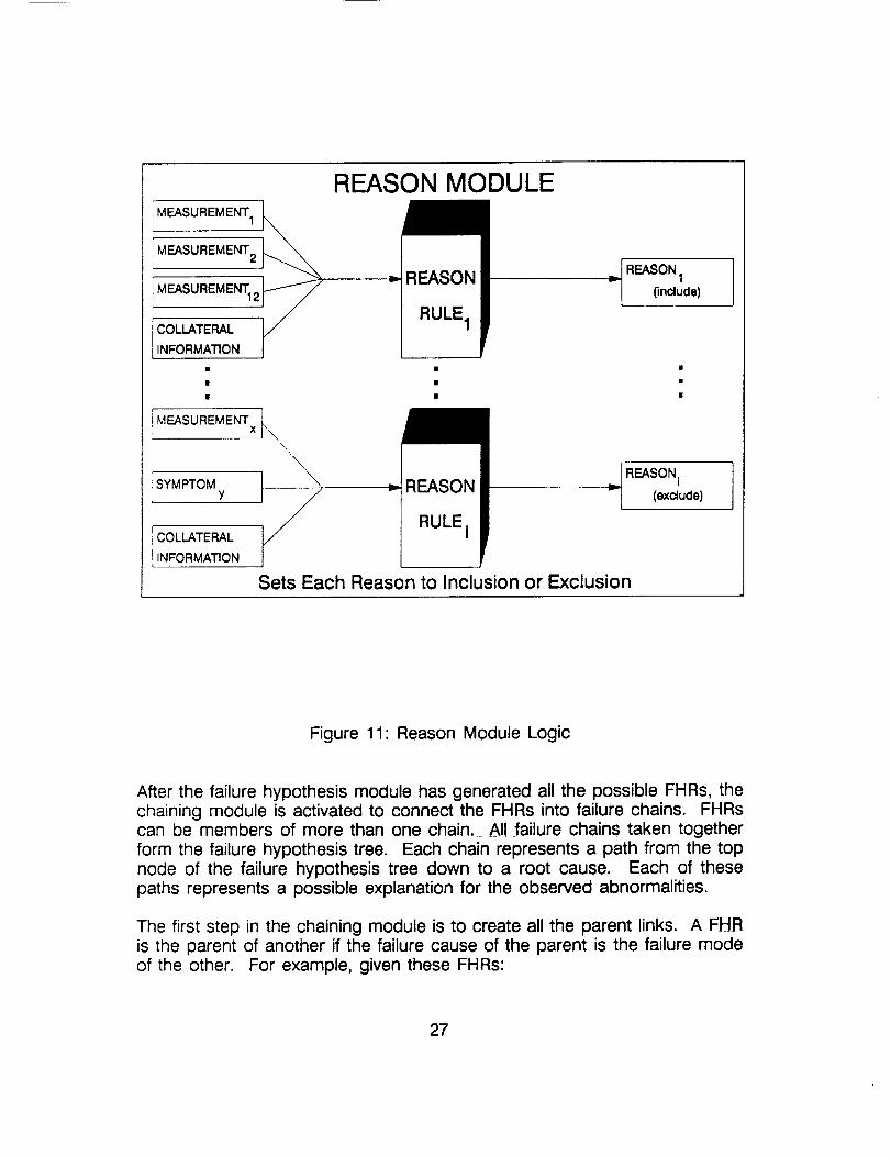
Usually, each failure in the FMEA has a subcause and the subcause has asubcause and so forth. Each will produce a failure hypothesis record.Although at time of creation these FHRs look independent, they are actuallyinterconnected by the subcause relationships. The chaining module isresponsible for creating chains (lists of FHRs) which show how the FHRs areinterconnected.
26
MEASUREMENT1
! MEASUREMENT2
MEASUREMENT12 _
r
i MEASUREMENTx
_SYMPTOMY
COLLATERAL
{INFORMATION
REASON MODULE
v REASON
RULE 1
I REASON 1
(include)
• |
t\\
_._ = REASONRULE i
Sets Each Reason to Inclusion or Exclusion
=l REASONi
(exclude)
Figure 11: Reason Module Logic
After the failure hypothesis module has generated all the possible FHRs, thechaining module is activated to connect the FHRs into failure chains. FHRscan be members of more than one chain. AI! failure chains taken together
form the failure hypothesis tree. Each chain represents a path from the topnode of the failure hypothesis tree down to a root cause. Each of thesepaths represents a possible explanation for the observed abnormalities.
The first step in the chaining module is to create all the parent links. A FHRis the parent of another if the failure cause of the parent is the failure modeof the other. For example, given these FHRs:
27
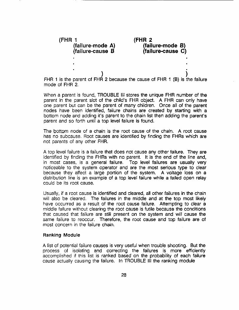
(FHR 1
(failure-mode A)(failure-cause B
(FHR 2
Ifailure-modefailure-cause _)
FHR 1 is the parent of FHR 2 because the cause of FHR 1 (B) is the failuremode of FHR 2.
When a parent is found, TROUBLE III stores the unique FHR number of theparent in the parent slot of the child's FHR object. A FHR can only haveone parent but can be the parent of many children. Once all of the parentnodes have been identified, failure chains are created by starting with abottom node and adding it's parent to the chain list then adding the parent'sparent and so forth until a top level failure is found.
The bottom node of a chain is the root cause of the chain. A root cause
has no subcause. Root causes are identified by finding the FHRs which arenot parents of any other FHR.
A top level failure is a failure that does not cause any other failure. They areidentified by finding the FHRs with no parent. It is the end of the line and,in most cases, is a general failure. Top level failures are usually verynoticeable to the system operator and are the most serious type to clearbecause they affect a large portion of the system. A voltage loss on adistribution line is an example of a top level failure while a failed open relaycould be its root cause.
Usually, if a root cause is identified and cleared, all other failures in the chainwill also be cleared. The failures in the middle and at the top most likelyhave occurred as a result of the root cause failure. Attempting to clear amiddle failure without clearing the root cause is futile because the conditionsthat caused that failure are still present on the system and will cause thesame failure to reoccur. Therefore, the root cause and top failure are ofmost concern in the failure chain.
Ranking Module
A list of potential failure causes is very useful when trouble shooting. But theprocess of isolating and correcting the failures is more efficientlyaccomplished if this list is ranked based on the probability of each failurecause actually causing the failure. In TROUBLE III the ranking module
28
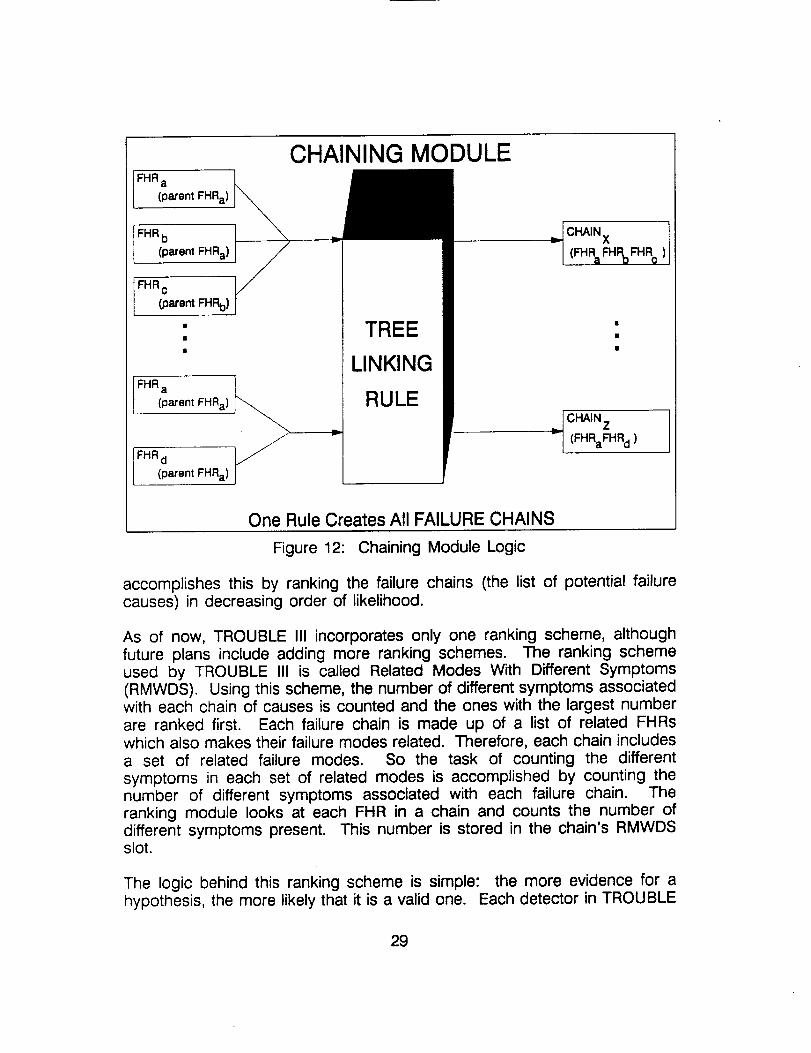
CHAINING MODULE
FHR a
(parent FHRa)
FHR b
(parent FHRa)
FHR c _/(parent FHRb)
FHR a
(parent FHRa)
FHR d
[ (parent FHRa)
TREE
LINKING
RULE
_CHAIN X 1
I CHAIN Z(FHRaFHR d )
One Rule Creates All FAILURE CHAINS
Figure 12: Chaining Module Logic
accomplishes this by ranking the failure chains (the list of potential failurecauses) in decreasing order of likelihood.
As of now, TROUBLE III incorporates only one ranking scheme, althoughfuture plans include adding more ranking schemes. The ranking schemeused by TROUBLE III is called Related Modes With Different Symptoms(RMWDS). Using this scheme, the number of different symptoms associatedwith each chain of causes is counted and the ones with the largest numberare ranked first. Each failure chain is made up of a list of related FHRswhich also makes their failure modes related. Therefore, each chain includesa set of related failure modes. So the task of counting the differentsymptoms in each set of related modes is accomplished by counting thenumber of different symptoms associated with each failure chain. Theranking module looks at each FHR in a chain and counts the number ofdifferent symptoms present. This number is stored in the chain's RMWDSslot.
The logic behind this ranking scheme is simple: the more evidence for ahypothesis, the more likely that it is a valid one. Each detector in TROUBLE
29
ill generates a single symptom, so the number of different symptoms in achain is equal to the number of independent pieces of evidence associatedwith the chain. The probability of a chain's cause being the actual causeincreases as the independent evidence associated with the chain increases.Therefore, a large count of different symptoms (RMWDS) in a chain impliesa higher probability of that chain's cause being the real cause.
Other ranking schemes include easiest to check and severity of failure.Neither of these have been incorporated into TROUBLE III as of yet. Easiestto check ranks the causes in the order that would be easiest for the operatorto verify. The idea being why do a complicated test procedure if a simplerone has the same probability of being at fault. If the easier to check onehappens to be the fault, checking it first eliminates the work of checking thedifficult one.
Ranking by severity of failure is a scheme that looks at the result of eachpossible failure cause and ranks them in order of the one that has theseverest consequences. This method is based on the idea that severe faultsshould be tested for first because if they exist they will do more damage.Failure causes that impact small areas can be left unattended until all theother possibilities have been checked more easily than a severe failurecause.
These methods will be incorporated when better system operating knowledgebecomes available.
Justification Module
The justification module answers the question of "Why is a particular failurechain included as a possible cause?". It justifies the chain's existence to theuser by retracing the logic TROUBLE III went through in creating the chain.
After the top level failure modes and root causes have been displayed to theuser, the user may want more information on why a particular failure causeappeared. By entering the justification module the user can obtain thedesired information on any of the chains on the screen.
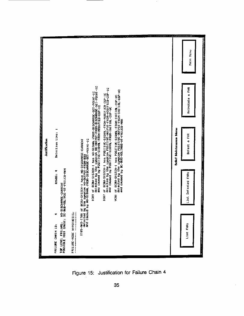
The justification module queries the user for the chain to justify and thenproceeds to backtrack through the chain displaying TROUBLE Ilrs reasoning.Starting with the top level failure, this module displays in a natural languageformat the failure mode, failure cause, failure symptoms, failed device andlocations for each link (FHR) in the chain. An example is shown in Figure15. It shows the justification of why the root cause "DC BUS Voltage VTFailed MAX" is a possible root cause for the failure mode "NO Discharge
3O
Current".
Besides giving the logic justification for each root cause, the justificationmodule also allows the user to believe or disbelieve any of FHRs in a chain.If the operator has good reason to believe that a failure mode and its causeis not a viable candidate, he/she can defeat the reason and remove thatFHR from all chains. Once a FHR's reason is defeated, the logic of the restof the chain falls apart and every root cause stemming from the defeatedFHR is no longer a possible candidate. After defeating a FHR's reason,TROUBLE III will redisplay the possible top level failure modes and rootcauses with all chains dependent upon the defeated FHR eliminated. AnyFHR's reason can be defeated, it does not have to be the top or bottomnode of the chain. The higher up in the chain the defeated FHR appears,the more chains will be eliminated from contention. Defeated chains arenever discarded, just suppressed from being printed.
The user also has the option of reinstating a defeated FHR. When thisoption is selected a menu appears with every defeated FHR being an option.The user can reinstate any or all defeated FHRs. Once the selections aremade the possible failure modes and causes are redisplayed including theones reinstated.
Input and Output Modules
The input module allows the user to directly alter measurement values. It isonly used for developing and testing TROUBLE IIl's diagnostic logic. WhenTROUBLE III is directly connected to hardware, input data will be acquiredfrom the hardware rather than from the input module.
The input module has two ways of entering or altering measurement valuesstored in the database: 1) load a test file or 2) manually enter themeasurement number and value one at a time.
If the user selects to enter new data by loading a file, TROUBLE III displaysa mouse sensitive menu which lists all possible test case files. Uponselection of a test file, TROUBLE III locates the desired file on the disk andloads the file into its working memory where input rules modify the existingmeasurement objects to correspond to the data in the test file. Once all ofthe data has been modified, the input module increments the clock andbegins the diagnostic process by activating the detection module.
If the manual input mode is chosen, TROUBLE III keeps prompting the userfor the measurement device number and its new value until the user has
entered all of his/her changes. For each device number entered, TROUBLE
31
III locates the corresponding measurement object and modifies it value tocorrespond to the user's input. After all changes are made, TROUBLE IIIincrements the clock and begins the diagnostic process by activating thedetection module.
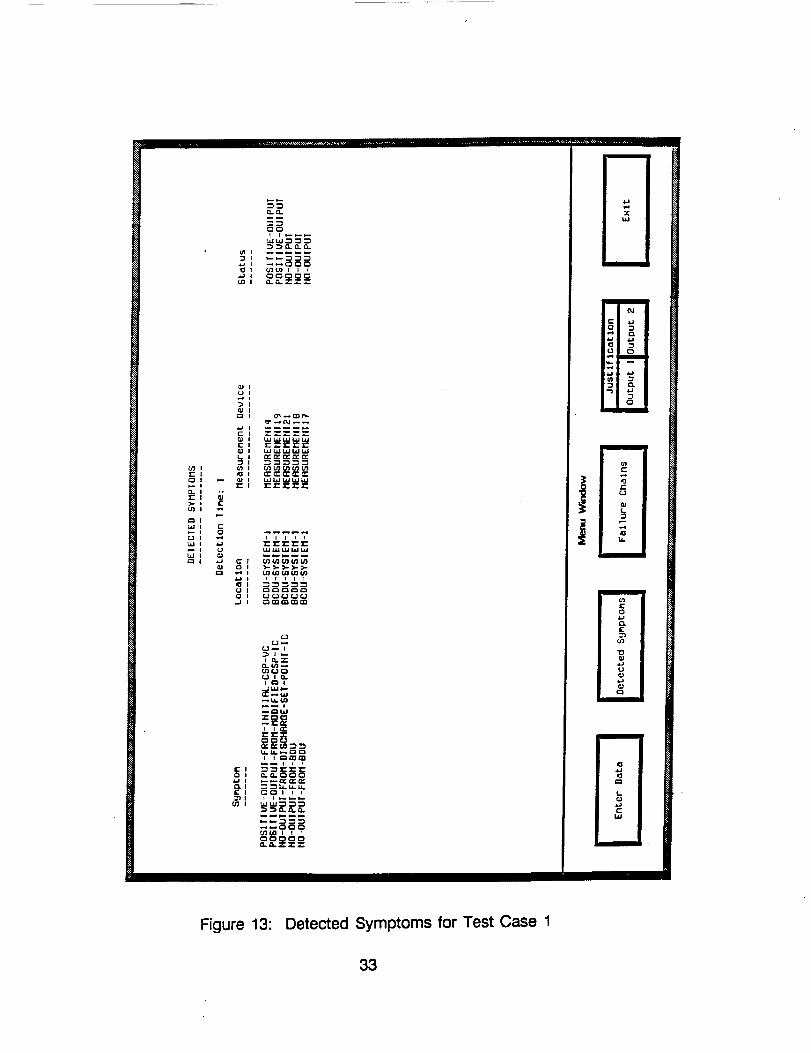
The output module is responsible for communicating the results of thediagnostics to the user. By selecting one of the mouse sensitive areas onthe bottom of the screen, the user controls what output is exposed on thescreen. By interacting with the output module the user is able to 1) invokethe input module, 2) view all symptoms detected, 3) view the FAILURE chainscreated, 4) invoke the justification module, 5) invoke the belief maintenanceprocedure or 6) EXIT the program.
Each of these options has its own window to display its results. The outputmodule determines which window is exposed to the user. In this wayTROUBLE III can switch back and forth between screens without having towaste time regenerating the outputs. This is especially evident in thedetected symptoms and failure chains screen. If TROUBLE II! regeneratedthe outputs for these screens every time the user selected them, a lot of timewould be wasted generating output that hadn't changed from the last time.The other screens are cleared each time they are selected because theyinvoke modules which generate different results each time depending on theuser responses to their prompts.
Figures 13-15 show output screens that are the result of running TROUBLEIII on Test Case 1. Figure 13 lists all the symptoms TROUBLE III found withthe conditions of the test case. Figure 14 displays the top level failures androot cause for the observed abnormalities ranked by RMWDS. Figure 15shows the justification for the fourth possible cause of Figure 14.
32
till
fllll
Figure 13: Detected Symptoms for Test Case 1
33
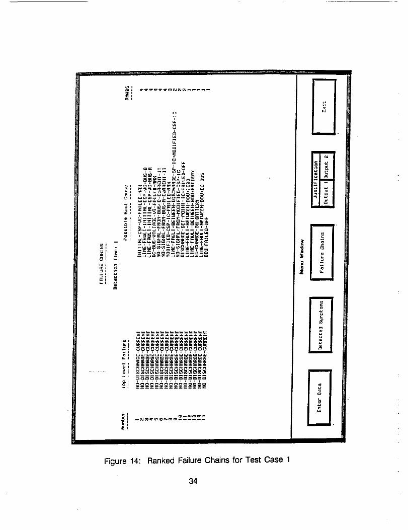
Figure 14:
i
i
lllltllllllllll
Ranked Failure Chains for Test Case 1
mm
mmmmm
r m
t
mm m -
34
I
II
II
l
Figure 15: Justification for Failure Chain 4
35
Implementation
The previous sections have outlined the overall design and logic of TROUBLEIII. Each of the modules in the design have been implemented using ARTand LISP code. Each module is made up of rules, objects and databases
that incorporate the design techniques of set-covering, FMEA, and transitions.After each module was developed and coded, it was tested to verify that itfunctioned properly. The next section describes the testing procedures.
Testing
Diagnostic expert systems, like TROUBLE i11, must gain the user'sconfidence. TROUBLE III uses a testing method to prove that it is accurateand reliable. The testing method was to test and to debug each moduleafter it was coded.
As each module was coded it was tested to make sure that the results
agreed with the expectations. Specific test cases with known results wereused as input and the outputs of the module were compared to the knownresults. If the output agreed, work began on the next module. If the resultsdisagreed, then the logic of the module was reviewed and alteredaccordingly.
To do this testing, a power system was needed that could be analyzed andthe results used in testing. Since the power system being designed by theproject contractor was incomplete, James Dolce of NASA Lewis ResearchCenter completed the unfinished control system design using proposedcomponents and configurations;'. As the actual design evolves, only thedatabase will change not the logic of TROUBLE IIl's rules.
A failure mode and effects analysis was performed on the system design todetermine failures and causes, needed measurements, and corresponding
symptoms. This failure knowledge was placed into failure objects,measurement objects, and detection rules. Next, test cases were developedthat simulated known failures.
Every module was tested with these cases and has produced the correctdiagnosis. The overall system can successfully diagnose failures as definedin the data base for our hypothetical power system.
Future Developments
The next major development in TROUBLE IIl's future is integrating it with atest bed. For the integration to be successful, issues surrounding data
36
acquisition must be resolved, a failure mode and effects analysis must beperformed on the test bed, symptom detection rules must be developed,and the diagnostic software integrated with test bed control software. Dataacquisition issues include determining the rate of acquisition and how toconvert the analog measurements into the measurement facts TROUBLE Illneeds.
Adding additional ranking schemes, as discussed in Chapter 4.2.8, is anotherenhancement planned for TROUBLE II1. Before implementing these, collateralinformation on troubleshooting and failure probabilities will have to be
gathered from an expert and incorporated into the design.
Another development will be to integrate TROUBLE III with the other expertsystems being developed in the Advanced Automation Lab of NASA LewisResearch Center. The results of the fault diagnoses of TROUBLE III will bean important input into the load scheduler and security expert systems 9.
DIAGNOSTIC EXAMPLE USING TROUBLE I!1
This chapter is intended to clarify the function of each module of TROUBLEIII by discussing, in detail, an example used in testing. The test system,failure mode and effects analysis and test conditions will be described. Thenthis chapter will follow the given test conditions through each module andexplain how each module reacts.
Test System
The Battery Charger/Discharger Unit (BCDU) used in testing TROUBLE IIIwas also used as the test system for this example. The purpose of theBCDU system is to charge the batteries when the solar arrays produce moreelectricity than used by the loads and discharge the batteries when the loadsuse more electricity than is produced. The batteries charge and dischargeat a rate that keeps the bus voltage constant.
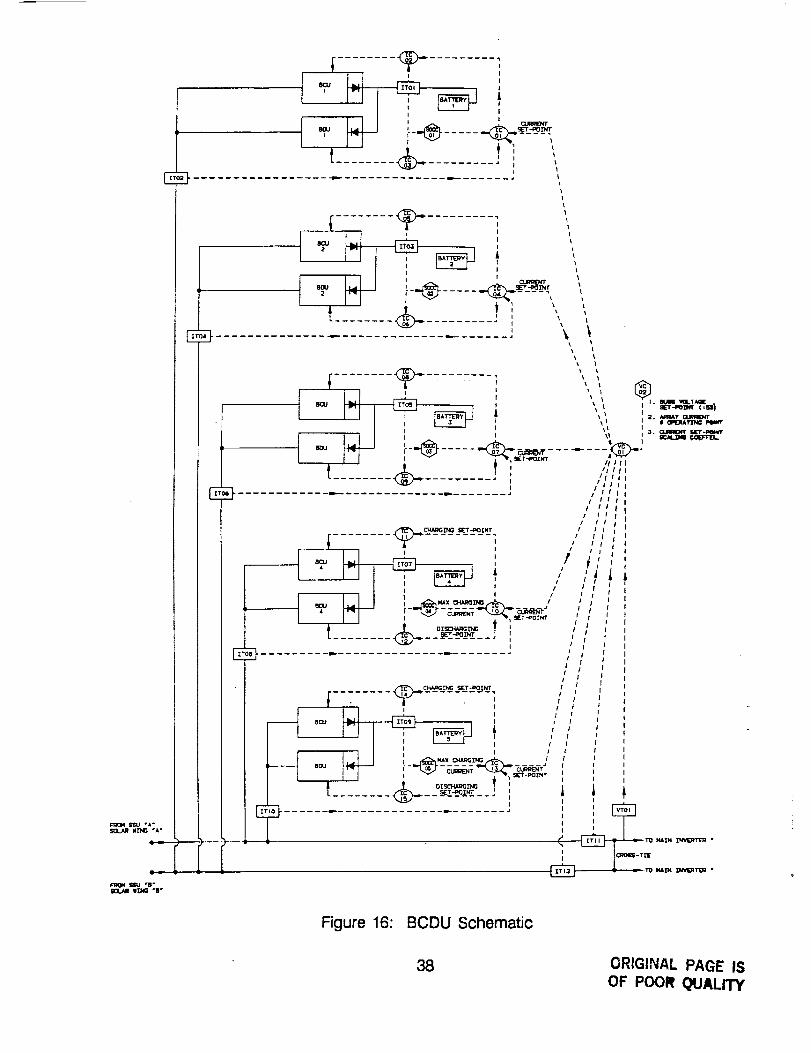
Figure 16 shows a schematic diagram of the BCDU design. Five parallelbatteries, each with their own charger and discharger are connected to thetwo parallel DC bus lines running from the solar arrays to the loads. Thecontrol scheme uses measurements from the solar arrays, the loads, thebatteries and the main bus along with constant set points for the
37
E
•II_ "B °
' |
-_-J i---_..... -_-_-_-I I ' _ I
Figure 16: BCDU Schematic
3B ORIGINAL PAGE ISOF POOR QUALITY
maximum bus voltage and charging current to control the amount ofdischarging or charging for each battery. Detailed explanation of the controlscheme is not important for this example and will not be discussed.
FMEA
A FMEA was performed on the BCDU system to define the failure knowledgeused by TROUBLE III in diagnosing the system. For each component of theBCDU system (ie VC01, IT01, IC03)= every possible cause and symptom forevery possible failure was described. Each unique failure-cause-symptomwas stored as a unique failure object. Once all the failure modes andcauses were identified, a failure hypothesis tree was created that shows howthe failure modes and causes are interconnected.
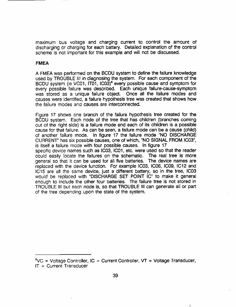
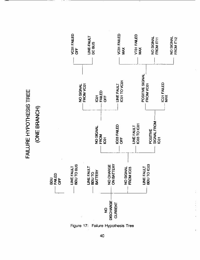
Figure 17 shows one branch of the failure hypothesis tree created for theBCDU system. Each node of the tree that has children (branches comingout of the right side) is a failure mode and each of its children is a possiblecause for that failure. As can be seen, a failure mode can be a cause (child)of another failure mode. In figure 17 the failure mode "NO DISCHARGECURRENT" has six possible causes, one of which, "NO SIGNAL FROM IC03",is itself a failure mode with four possible causes. In figure 17specific device names such as IC03, IC01, etc. were used so that the readercould easily locate the failures on the schematic. The real tree is moregeneral so that it can be used for all five batteries. The device names arereplaced with the device function. For example IC03, IC06, IC09, IC12 andIC15 are all the same device, just a different battery, so in the tree, IC03would be replaced with "DISCHARGE SET POINT IC" to make it generalenough to include the other four batteries. The failure tree is not stored inTROUBLE III but each node is, so that TROUBLE III can generate all or partof the tree depending upon the state of the system.
aVC = Voltage Controller, IC = Current Controller, VT = Voltage Transducer,IT = Current Transducer
39
= o_ _ _o_>_ ._ >_ o_-7,,
.-I<cqzt-(.9
0OrrZu.
I I l I
IJJLUn-
O3COLLI7-I--O0.>-7-
LLIri-D-.I
,,<
7"0Z
n--mLUZ0
_Sz o
0On"Zu. __o =_
I1 l ,
O-- o
[ I
w_
0 _ _ ZO
<oZO_ '<0
_0 w_On- ZoZu. =:]_n
Figure 17:
ILl
-- 0
Failure Hypothesis Tree
40
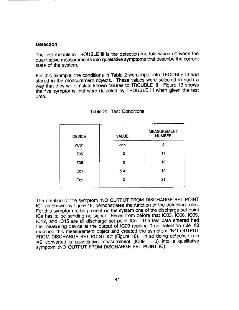
Detection
The first module in TROUBLE III is the detection module which converts the
quantitative measurements into qualitative symptoms that describe the currentstate of the system.
For this example, the conditions in Table 2 were input into TROUBLE III andstored in the measurement objects. These values were selected in such away that they will simulate known failures to TROUBLE III. Figure 13 showsthe five symptoms that were detected by TROUBLE III when given the testdata.
Table 2: Test Conditions
DEVICE
VC01
IT05
IT06
IC07
IC09
VALUE
22.5
0
0
5.4
0
MEASUREMENTNUMBER
4
17
18
19
21
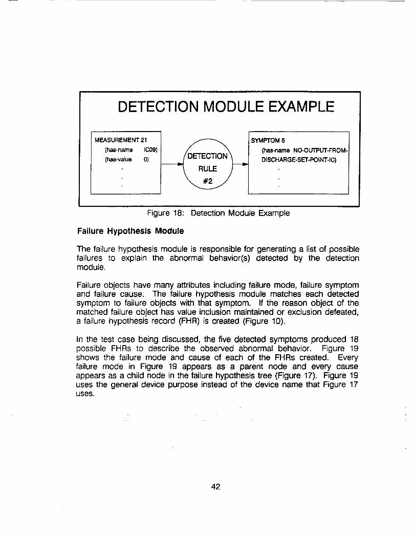
The creation of the symptom "NO OUTPUT FROM DISCHARGE SET POINTIC", as shown by figure 18, demonstrates the function of the detection rules.For this symptom to be present on the system one of the discharge set pointICs has to be sending no signal. Recall from before that IC03, IC06, IC09,IC12, and IC15 are all discharge set point ICs. The test data entered hadthe measuring device at the output of IC09 reading 0 so detection rule #2matched this measurement object and created the symptom "NO OUTPUTFROM DISCHARGE SET POINT IC" (Figure 18). In so doing detection rule#2 converted a quantitative measurement (IC09 = 0) into a qualitativesymptom (NO OUTPUT FROM DISCHARGE SET POINT IC).
41
DETECTION MODULE EXAMPLE
MEASUREMENT 2.1
(has-name IC09)
(has-value 0)
SYMPTOM 5
(has-name NO-OUTPUT-FROM-
DISCHARGE-SET-POINT-IC)
Figure 18: Detection Module Example
Failure Hypothesis Module
The failure hypothesis module is responsible for generating a list of possiblefailures to explain the abnormal behavior(s) detected by the detectionmodule.
Failure objects have many attributes including failure mode, failure symptomand failure cause. The failure hypothesis module matches each detectedsymptom to failure objects with that symptom. If the reason object of thematched failure object has value inclusion maintained or exclusion defeated,a failure hypothesis record (FHR) is created (Figure 10).
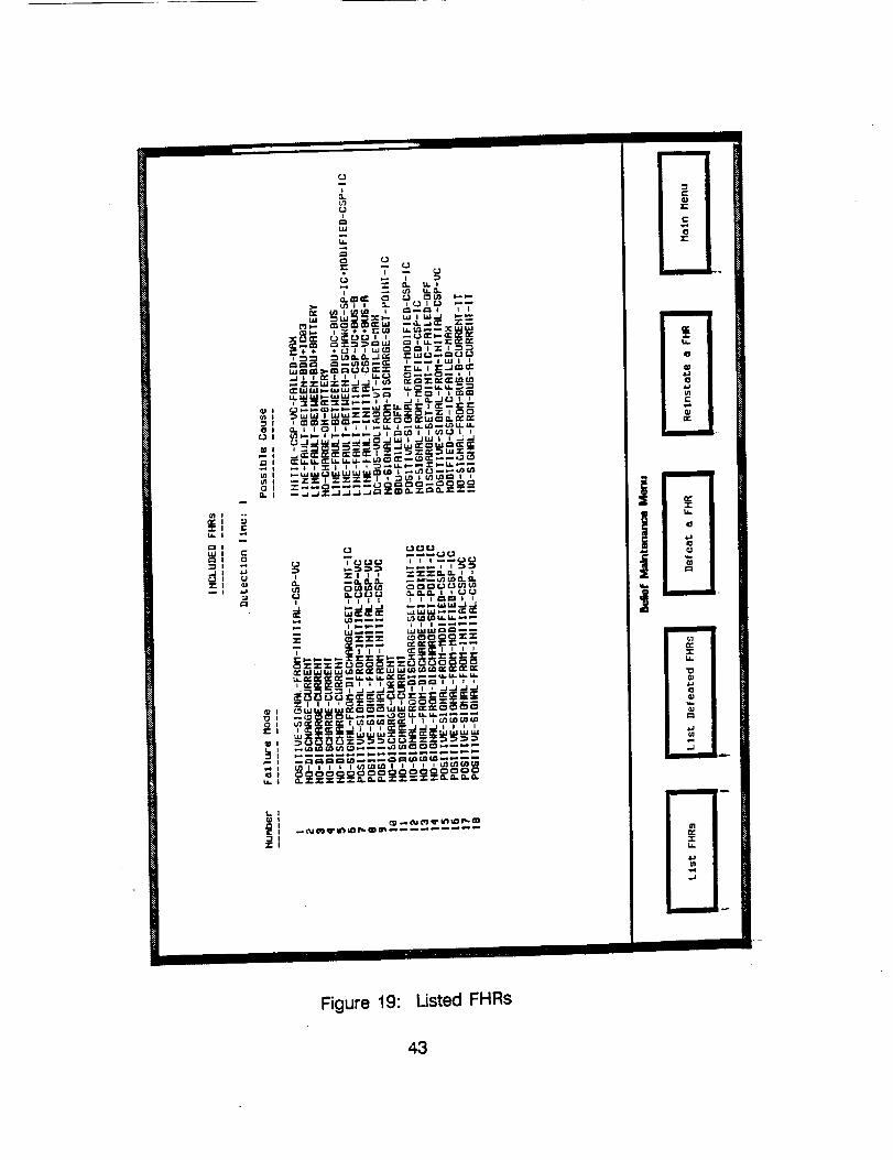
In the test case being discussed, the five detected symptoms produced 18possible FHRs to describe the observed abnormal behavior. Figure 19shows the failure mode and cause of each of the FHRs created. Everyfailure mode in Figure 19 appears as a parent node and every causeappears as a child node in the failure hypothesis tree (Figure 17). Figure 19uses the general device purpose instead of the device name that Figure 17uses.
42
Illl Illllll
Figure 19: Listed FHRs
43
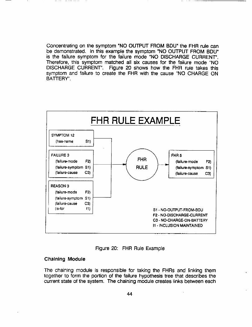
Concentrating on the symptom "NO OUTPUT FROM BDU" the FHR rule canbe demonstrated. In this example the symptom "NO OUTPUT FROM BDU"is the failure symptom for the failure mode "NO DISCHARGE CURRENT".Therefore, this symptom matched all six causes for the failure mode "NODISCHARGE CURRENT''. Figure 20 shows how the FHR rule takes thissymptom and failure to create the FHR with the cause "NO CHARGE ONBATFERY".
FHR RULE EXAMPLE
SYMPTOM 12
(has-name S1)
FAILURE 3
(failure-mode F2)
(failure-symptom Sl)
(failure-cause C3)
REASON 3
(failure-mode F2)
(failure-symptom Sl)
(failure-cause C3)
(is-for I1)
FHR 5
(failure-mode F2)
(failure-symptom S1)
(failure-cause C3)
S1 - NO-OUTPUT-FROM-BDU
F2. NO-DISCHARGE-CURRENT
C3 - NO-CHARGE-ON-BA'I-rERY
I1 - INCLUSION MAINTAINED
Figure 20: FHR Rule Example
Chaining Module
The chaining module is responsible for taking the FHRs and linking themtogether to form the portion of the failure hypothesis tree that describes thecurrent state of the system. The chaining module creates links between each
44
parent and child in the tree, then uses these relationships to form the chains(lists of FHRs) that go from a top level failure to a root cause. A root causeis a cause that has no children.
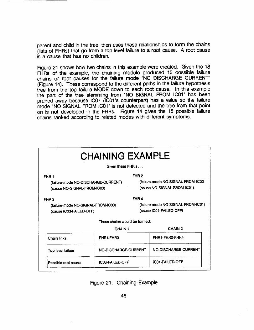
Figure 21 shows how two chains in this example were created. Given the 18FHRs of the example, the chaining module produced 15 possible failurechains or root causes for the failure mode "NO DISCHARGE CURRENT"
(Figure 14). These correspond to the different paths in the failure hypothesistree from the top failure MODE down to each root cause. In this examplethe part of the tree stemming from "NO SIGNAL FROM IC01" has beenpruned away because IC07 (IC01's counterpart) has a value so the failuremode "NO SIGNAL FROM IC01" is not detected and the tree from that pointon is not developed in the FHRs. Figure 14 gives the 15 possible failurechains ranked according to related modes with different symptoms.
CHAINING EXAMPLEGiven these FHR's...
FHR 1
(failure-mode NO-DISCHARGE-CURRENT)
(cause NO-SIGNAL.FROM-IC03)
FHR 3
(failure-mode NO-SIGNAL-FROM-IC03)
(cause IC03-FAILED-OFF)
FHR 2
(failure-mode NO-SIGNAL-FROM-IC03
(cause NO-SIGNAL-FROM-IC01)
FHR 4
(failure-mode NO-SIGNAL-FROM-IC01)
(cause IC01-FAILED-OFF)
These chains would be formed:
CHAIN 1 CHAIN 2
Chain links FHR1-FHR3 FHR1-FHR2-FHR4
Top level failure NO-DISCHARGE-CURRENT NO-DISCHARGE-CURRENT
Possible root cause IC03-FAILED-OFF IC01-FAILED-OFF
Figure 21: Chaining Example
45
Justification Module
The justification module justifies a user selected chain's existence bydisplaying the logic used by TROUBLE III in creating the chain.
Chain 4 was selected to be justified in this example and the results appearin Figure 15. If one compares the justification of chain 4 to the failurehypothesis tree, they would see that the justification module displays abranch of the tree, from top failure to root cause, and explains in Englishhow "DC BUS VOLTAGE VT FAILED MAX" could be a root cause of thefailure "NO DISCHARGE CURRENT".
Looking at Figure 14 also shows how chain 4 got a RMWDS of four. If onecounts the number of different symptoms that appear in the justifications,they will come up with four RMWDS.
Belief Maintenance
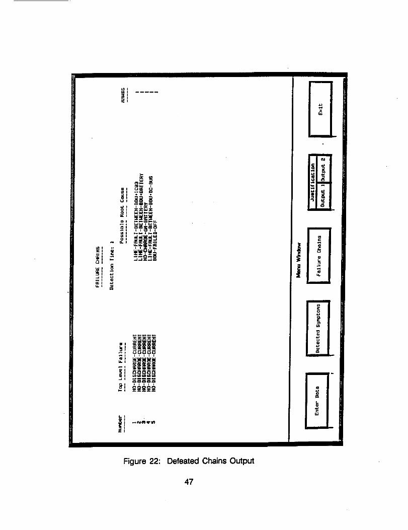
The belief maintenance module allows a user to defeat or reinstate any FHR.If the user desires to see the chaining results if a selected FHR neverexisted, he/she can defeat that particular FHR causing all chains containingthat FHR to disappear. This has the effect of pruning the failure hypothesistree at the desired node.
In this example, FHR 10 was defeated and Figure 22 displays the resultingchains. Comparing this to the failure hypothesis tree one can see thatdefeating FHR 10 has the same affect as pruning the tree at the "NO SIGNALFROM IC03" node. Only the five chains that do not contain that failure modeare displayed. If FHR 10 was reinstated all the original chains wouldreappear.
46
J
LL
"]l
Figure 22: Defeated Chains Output
47
CONCLUSION
This thesis has described an object oriented expert system TROUBLE i11,which is intended to automate the fault diagnostics of Space StationFreedom's power system.
It has been shown that this type of automation is desirable in a space basedsystem to reduce the number of needed personnel, increase reliability andspeed up response time to faults.
The design of TROUBLE III was complicated by the fact that Space StationFreedom's power system design keeps changing. Adapting an expertsystem to this dynamic, evolving system requires a flexible design. Threetypes of expert systems were studied: rule-based, set-covering, and model-based. A set-covering approach was selected because it offered the neededflexibility that rule-based and model-based systems lack. In set-covering theflexibility is gained because failure knowledge about the system is stored indatabases rather than encoded in rules.
Besides using a set-covering approach, TROUBLE III makes use of thefollowing techniques: Failure Modes and Effects Analysis (FMEA), Petri nettransitions, reasoned assumptions and Related Modes With DifferentSymptoms (RMWDS). FMEA is used to produce the known failure database.Transitions control the flow of the program by determining which module tomake active, while reasoned assumptions and RMWDS are methods thatreduce the work necessary to determine the most probable cause.
Besides expanding Zisman's work with Petri net transitions, an importantoutcome of TROUBLE IIl's development was that it demonstrated it waspossible to combine the strengths of set-covering, FMEA, Petri net transitions,and reasoned assumptions into one diagnostic expert system. Thesetechniques are not new ideas individually but combining them all together isunique.
TROUBLE IIl's main strength is its quick adaptability to any system changes.By performing a FMEA on the new system and changing the detection rules,TROUBLE III can be adapted to handle diagnostics on any system. Failureknowledge not being hard coded into rules means no diagnostic rules needbe altered.
As with any rule-based or set-covering expert system, the main limitation ofTROUBLE 111is that it can only detect faults that have been described to itby a human expert. It cannot make inferences.. If a fault appears on thesystem that was not described by the human expert, TROUBLE III has no
48
knowledge of that fault and it will go undetected. The failure knowledge ofTROUBLE III is limited by the human expert. The more comprehensive thehuman expert is in identifying the possible failures and causes of the system,the better TROUBLE III becomes.
Another limitation of TROUBLE III is that it will not detect incipient faults, onlystatic faults. TROUBLE III does not have the capability to monitor theperformance history of each component in an attempt to predict and negatepossible failures before they occur. It can only detect and isolate faults thathave already occurred on the system.
A prototype battery charge-discharge control system was designed to testTROUBLE II1. A FMEA was performed on this design with the consequentfailure modes and causes being stored in a failure database. A set ofdetection rules was written to detect the symptoms of these failure modes.Test cases were developed to simulate certain failure modes and the testresults were compared to the predicted results to verify the rule's logic.
TROUBLE III is a functioning diagnostic expert system but its development isnot complete. Several improvements are planned to make TROUBLE III abetter system: integrating TROUBLE III with a test bed, adding additionalranking schemes, improving the graphics, and interconnecting TROUBLE IIIwith other expert systems.
Even though TROUBLE III has been designed specifically to handle SpaceStation Freedom's dynamic, evolving power system, it is not limited to thisspecific application. The flexibility that had to be incorporated in the designto handle the changing power system makes TROUBLE III easily adaptableto any diagnostic system on Earth or in space.
49
°
=
3_
°
°
.
o
8.
.
10.
REFERENCES
Biglari, H. and Cheng, C. and Vachtsevanos, G.; "Fault TolerantIntelligent Controller For Space Station Subsystems"; 1988IECEC Proceedings of the 23rd intersociety Energy ConversionEngineering Conference; Denver, CO.; July 31 - Aug 5 1988;Vol. 3 pp 313-318
Cardozo, E. and Talukdar, S.; "A Distributed Expert System For FaultDiagnosis"; IEEE TRANSACTIONS on Power Systems; Vol. 3,No. 2; pp 641-646; May 1988
Culbert, C. and Boarnet, M.; "AI Applications for the Space Station";Elsevier Science Publishers B.V. (North-Holland); Robotics 4; pp35-40; 1988
D'Ambrosio, A.; "PERF-EXS, An Expert System For Diagnosing PowerPlants: Design Criteria and Implementation Details.";Proceedings 3rd Annual Expert Systems Conference andExposition; Detroit, MI; April 4-6, 1989; pp 83-94
Davis, R. and Hamscher, W.; "Model-BasedTroubleshooting"; M.I.T. Artificial IntelligenceCambridge, MA.; July, 1988
Reasoning:Laboratory,
Dolce, J.; "An Integrated Approach to Space Station Power SystemAutonomous Control"; IECEC '87 Proceedings of the 22ndintersociety Energy Conversion Engineering Conference;Philadelphia, PA; Vol. 1; pp 499-508; August 10-14, 1987
Dolce, J.; Private Communications; August, 1989
Dolce, J. and Faymon, K.; "Automating the U.S. Space Station'sElectrical Power System"; Optical Engineering; Vol. 25, No. 11pp 1181-1185; November, 1986
Dolce, J. and Mellor, P. and Kish, J.; "Automated Electric PowerManagement and Control for Space Station Freedom"; 25thIntersociety Energy Conversion Conference; Reno, Nevada;August 12-17, 1990
Doyle, J.; "Methodological Simplicity in Expert System Construction:The Case of Judgements and Reasoned Assumptions."; The AIMagazine; Summer 1983; pp 39-43
5O
11.
12.
13.
14.
15.
16.
17.
18.
19.
20.
Fesq, L. and Stephan, A.; " Advances in Spacecraft Autonomy UsingArtificiaJ Intelligence Techniques"; TRW Space and TechnologyGroup, Redondo Beach, CA
Freeman, K. and Walsh, R.; "Concurrent Development of FaultManagement Hardware and Software in the SSM/PMAD"; 1988IECEC Proceedings of the 23rd Intersociety Energy ConversionEngineering Conference; Denver, CO.; Vol 3; pp 307-312; July31 -August 5, 1988
Lee, S. and Lollar, L.; "Development of a Component Centered FaultMonitoring and Diagnosis Knowledge Based System for SpacePower System"; 1988 IECEC Proceeding of the 23rd IntersocietyEnergy Conversion Engineering Conference; Denver, CO.; Vol.3;pp 377-382; July 31 - August 5, 1988
Leinweber, D.; "Expert Systems in Space"; IEEE Expert; pp 26-36;Spring 1987
Milne, R.; "Strategies for Diagnosis"; IEEE Transactions on Systems,Man, and Cybernetics"; Vol. SMC-17, No 3; pp 333-339;May/June 1987
Omarali, Z. and Savage, G.; "Efficiency Considerations in the Designof Expert Diagnostic Systems"; Proceedings 3rd Annual ExpertSystems Conference and Exposition; Detroit, M I.; pp 15-24; April4-6, 1989
_obaji6, D. and Pao, Y.; "An Artificial Intelligence System for PowerSystem Contingency Screening"; IEEE Transaction on PowerSystems; Vol. 3, No. 2; pp 647-652; May 1988
Teren, F.; "Space Station Electric Power System Requirements andDesign"; IECEC '87 Proceedings of the 22nd Intersociety EnergyConversion Engineering Conference; Philadelphia, PA; Vol. 1; pp39-47; August 10-14, 1987
Yoon,
Walls,
W. and Hammer, J.; "Deep-Reasoning Fault Diagnosis: An Aidand a Model" IEEE Transactions on Systems, Man andCybernetics; Vol. 18, No. 4; pp 659-675; July/August 1988B.; "STARR: An Expert System For Failure Diagnosis In a SpaceBased Power System"; 1988 IECEC Proceedings of the 23rdIntersociety Energy Conversion Engineering Conference; Vol. 3;
51
21.
22.
23.
24.
pp 303-306; July 31 - August 5, 1988
Wang, C., Zeanah, H., Anderson, A., Patrick, C., Brady, M., and Ford,D.,; "Automatic Detection of Electric Power Troubles (ADEPT)";NASA, Marshal Space Flight Center; Huntsville, AL; 1988
Weeks, D.; "Automation of the Space Station Core Module PowerManagement and Distribution System"; NASA, Marshal SpaceFlight Center; Huntsville, AL.; 1988
Zisman, M.; "Use of Production SYstems for Modeling AsynchronousConcurrent Processes"; in Pattern-Directed Inference Systems;Waterman, D.A. and Hayes-Roth, F.; eds.; Academic Press; NewYork; 1978; pp 53-68
Unpublished Document; "Chronology of Space Station Freedom PowerDistribution System"; Space Station Freedom Electricla SystemsDivision, NASA Lewis Research Center; Cleveland, OH; 1990
52

ii
rlJ/ ISA Report Documentation PageNational Aeronautics and
Space Administration
1. Report No. 2. Government Accession No.
NASA CR - 187113
4. Title and Subtitle
TROUBLE III: A Fault Diagnostic Expert System for Space StationFreedom's Power System
7. Author(s)
David B. Manner
g. Performing Organization Name and Address
Sverdrup Technology, Inc.
Lewis Research Center Group
2001 Aerospace ParkwayBrook Park, Ohio 44142
12. Sponsoring Agency Name and Address
National Aeronautics and Space AdministrationLewis Research Center
Cleveland, Ohio 44135 - 3191
3. Recipienfs Catalog No.
5, 'Re_od Date
6. Performing Organization Code
8. Performing Organization Report No.
None (E - 6188)
10. Work Unit No.
488 - 51- 03
11. Contract or Grant No.
NAS3 - 25266
13. Type of Report and Period Covered
Contractor ReportFinal
14. Sponsoring Agency Code
15. Supplementary Notes
Project Manager, Pam Mellor, Electrical Systems Division, NASA Lewis Research Center, (216) 433-8328.
16. Abstract
Designing Space Station Freedom has given NASA many opportunities to develop expert systems that automateonboard operations of space based systems. This paper describes one such development, TROUBLE ]II, an expert
system that has been designed to automate the fault diagnostics of Space Station Freedom's electric power system,TROUBLE l-ITs design is complicated by the fact that Space Station Freedom's power system is evolving and
changing. TROUBLE ]]I had to be made flexible enough to handle system changes with minimal changes to the
program. Three types of expert systems_were studied: rule-based, set-covering and model-based. A set-coveringapproach was selected for TROUBLE 11I because it offered the needed flexibility that was missing from the otherapproaches. With this flexibility, TROUBLE 1TI is not limited to Space Station Freedom applications, it can easily beadapted to handle any diagnostic system.
17. Key Words (Suggested by Author(s))
Expert systemsFaults
Diagnosis
18. Distribution Statement
Unclassified - Unlimited
Subject Category 18
i lg. Security Classif. (of the report) 20. Secudty Classif. (of this page) 21. No. of pages 22. Price*
Unclassified Unclassified 54 A04
i
NASAFORM1626OCT86 *Forsale bythe NationalTechnicalInformation Service,Springfield,Virginia 22161
!_,__r_._T[_ _5_ PRECEDING PAGE BLANK NOT FILMED