Embed Size (px)
Citation preview
Report 04-03-00974 Rev. 0.00
DSB - Expert Assessment of IC4/2
Project-No.: 14.104.00
EXPERT ASSESSMENT REPORT IC4/2
SBB AG Passenger Traffic Operating Sales Wylerstrasse 123/125 Ch-3000 Bern 65 Switzerland Tel. +41 51 220 69 96 E-Mail: [email protected]
PROSE Ltd.Zuercherstrasse 41CH-8400 Winterthur
SwitzerlandTel: +41 52 262 74 00Fax: +41 52 262 74 01 E-mail: [email protected]
Report 04-03-00974 Rev. 0.00 Preamble II
This document discloses subject matter in which the PROSE Ltd., Winterthur (Switzerland), has proprietary rights. Neither receipt nor possession thereof confers any right to reproduce or disclose the document, any part thereof, any information contained therein, or any physical article or device, or to practise any methods or process, except by written permission from or written agreement with, PROSE Ltd., Winterthur (Switzerland). This document is computer-generated and valid without signature. 04-03-00974 0.00 -
name date
prepared C. Bellon, L. Müller, H. Voigt, R. Zimmerli 15.10.2014
checked R. Mühlemann 03.12.2014
released C. Deiss 03.12.2014
Distribution
company / department / name remarks
DSB / IC4 Program Team / J.B. Johansen / S.S. Christensen
SBB / Passenger Traffic Operating / R. Mühlemann
PROSE
Report 04-03-00974 Rev. 0.00 Preamble III
04-03-00974 0.00 -
Revision Index prepared checked released date
04-03-00974 L. Müller R. Mühlemann C. Deiss 03.12.2014
Rev.
Rev.
Rev.
Rev.
Rev.
Modifications
revision description
Report 04-03-00974 Rev. 0.00 Preamble IV
04-03-00974 0.00 -
Executive Summary
Danske Statsbaner (DSB) has commissioned PROSE Ltd. to undertake an independent external assessment of the current situation of the IC4/IC2 project. The assessment is being undertaken by PROSE with consultant support from Swiss Federal Railways.
DSB has 82 IC4 4-coaches and 23 IC2 2-coaches diesel trainsets. These trainsets proved not to be suitable for operation. DSB found itself in the unique situation where a train operator is taking over the responsibility of completing newly built trainsets, instead of the manufacturer.
This assessment is focussed on the IC4 trainsets. The objective is to assess if it is worthwhile for DSB to continue spending resources on the train types IC4 and IC2 and if so, to what extent. It should be assessed in detail if the goals defined in the deployment plan by DSB regarding availability, reliability and functionality are realistic and if they can be met by the measures taken by DSB, and if not, what measures should be additionally defined.
By end of October 2014 the IC4 fleet performed a total mileage of 10.8 Mio km, 30% this year. Currently the trainsets are limited to operate in single traction and the maximum speed is reduced.
Due to the individual trainset configuration status, error finding and root cause analysis is more difficult and time consuming. Due to the poor reliability of the trainset and additional inspections, the maintenance efficiency is low which leads to high operational costs.
The final availability goal to have 74 IC4 trainsets in operation in 2019 is realistic since DSB has the required maintenance infrastructure as well as procedures in place to support this availability deployment. The current availability requirement to have 32 trainsets ready for operation twice a day is achieved.
The final reliability goal of 20,000 km mean distance between failures is in the long term realistic compared to other vehicles and operators. Currently reliability is not given priority over availability and functionality. The reliability goal is not achievable, and furthermore the improvement potential addressed is not even enough to address the today’s goal.
The final functionality goals assessed are realistic from a technical point of view. The intermediate phase (fixed couplings and 180 km/h) is delayed. All other goals are still achievable.
Measures defined by DSB are pointing in the right direction. However, additional measures are required to achieve the goals set out in the deployment plan. The engineering capacity should be increased by at least 12 Full-time Equivalent (FTE) to improve failure analysis, set up the task force for the power pack and defining measures and an increase in the workshop staff by at least 40 FTE is required. This is to speed up the “Rebuild and Campaigns to the IC4 and IC2 fleet“ (CFG) implementation.
Five designated IC4 trainsets shall be prioritised for use to collect mileages so that an indication can be obtained as to how the rest of the fleet will perform at a later stage.
The defined processes of IC4 program team shall be followed consequently and conscientiously. In general the organisation and quality management system are sufficient to reach the goals.
The goal to operate in fixed double traction is dependent upon the software approval of the “Train Computer and Monitoring System”. The defined modifications have to be properly validated.
Report 04-03-00974 Rev. 0.00 Preamble V
04-03-00974 0.00 -
The root cause analysis for fractures in the damper support of the axle box housing has to be completed.
The brake system has to be properly analysed and a validation plan for the new blending parameters needs to be set up.
Due to the high number of failures identified in the power pack and the complexity of the system, the power pack has to be analysed by the task force. The current solution on the power pack and the axle box housing is indicating weaknesses and this could lead to major design changes.
The balance with recommended measures in 2019 is 111.2 Mio DKK, 1.5 Mio DKK per trainset (74 trainsets). Taking into account the risks for a design change the balance can vary from 0.7 Mio DKK to -0.7 Mio DKK per trainset. This balance is based on the scope considered within this assessment. Therefore additional costs may occur.
Due to the delay in the procurement of the trainsets and therefore the shorter usable life cycle of the fleet, the investment made is poor. In the current situation the trains cannot be operated as expected but the investment to reach the deployment plan is known based on defined and recommended measures by this assessment. This allows a comparison with alternative solutions. Hence DSB advised development of the trainsets according to the deployment plan in order to allow an operation of the fleets on their natural lifecycle. Regardless of the amount of trainsets used and their duration of operation, the trainsets only have a value if the functionality and the reliability goals are reached. It is recommended that the IC4 trainsets are operated mainly in long distance traffic.
Today is a completely different situation compared to October 2011, where the Atkins report was elaborated. Atkins concluded that the fundamental systems and major items of equipment fitted to IC4 trainsets are sound and are currently operating reliably. Unfortunately now this is not the case as identified during the technical risk assessment.
The assessment has been carried out within a limited timeframe but with the aim to cover all necessary topics related to the IC4 program. This means that the assessment is based on the interviews performed and the documentation provided and is of a limited scope.
This technical assessment does cover all currently addressed issues, but future issues could occur. Due to reasonable suspicion other systems also fitted to trainsets might be incompletely engineered.
Report 04-03-00974 Rev. 0.00 6 / 84
04-03-00974 0.00 -
Content
1 Introduction 7
2 Goals set by DSB for the IC4 fleet 10
3 Assessment Results 11
4 Current status of the IC4 fleet 17
5 Financial appraisal IC4 trainsets 20
6 Appraisal “Organisation” 23
7 Appraisal “Quality management” 26
8 Appraisal “Workshop Performance” 31
9 Appraisal “MDBF Improvement and goals” 37
10 Appraisal “Technical risk assessment of main functions” 39
11 Differences in conclusion to the Atkins report 82
12 Abbreviations, Terminology 83
13 Appendices 84
Report 04-03-00974 Rev. 0.00 7 / 84
04-03-00974 0.00 -
1 Introduction DSB has commissioned PROSE Ltd. to undertake an independent external assessment of the current situation of the IC4/IC2 project in terms of whether it is worthwhile for DSB to continue spending resources on the train types IC4 and IC2. The assessment is being undertaken by PROSE with consultant support from Swiss Federal Railways (SBB).
1.1 Task Definition The assessment shall give answers to the following questions:
• Are the goals defined by DSB regarding availability and reliability realistic and can they be met by the measures taken by DSB, and if not, what measures should be additionally defined?
• Are the goals of DSB concerning performance and trainset availability in 2019 realistic? If not, what is a realistic goal relative to economy and technique? Are the measures defined by DSB already enough? If not, what are the consequences of additional measures seen from a technical, economical, operational and safety point of view?
• Is the deployment plan and performance plan of the IC4 economically viable relative to the fact that that the Danish lines are going to be electrified? Is the service life of the IC4/IC2 economically affected by the purchase of new trains?
1.2 Assignment The assignment has been carried out by PROSE in close cooperation with SBB and support of ENOTRAC. The assessment has been carried out between 26 August and 4 December 2014. Onsite visits were performed at DSB headquarters in Høje Tåstrup, as well as the workshops Sonnesgade and Augustenborggade in Århus and Kastrup Airport Copenhagen (KAC). During the visits various inspections, meetings and interviews were carried out. Besides the DSB maintenance internal partners Trafikstyrelsen, DSB operation, DSB economics and DSB safety were also interviewed.
1.3 Approach
Due to its complexity the assessment was divided into two phases.
The first phase focused on the collection of information in order to become acquainted with the design of the trainset and the organisation itself, the defined measures and the issues of the systems. This phase was performed in three weeks between 26 August and 12 September 2014. The goal was to define and prioritise the focus areas to be assessed in the second phase. The second phase focused firstly on the focus areas defined by the assessment team, which were: organisation, quality management, workshop performance, Mean Distance Between Failure causing a delay > 5min (MDBF) improvement and goals, technical risk assessment of main functions.
Report 04-03-00974 Rev. 0.00 8 / 84
04-03-00974 0.00 -
The starting point of the technical risk assessment is the list of the main functions that have to be improved as well as the required CFGs and modifications to be in place in order to achieve the following identified main technical functions:
• Coupling multiple traction: These modifications should relieve the limitation of single traction operation
• Brake (Blending, Wheels Slide Protection, …): These modifications should relieve the current speed reductions
• Axle box housing: Cracks were detected in the lower wheel-set-bearing-housing.
• Power pack: Several integration problems and defects of components in the power pack (PP) reduce the availability of the trainset.
The focus has been placed on the critical CFGs that are about to be implemented and on the main functions of the trainsets. Secondly, to develop a comprehensive overview of the findings of the focus areas and the financial assessment in order to answer the questions raised in the task definition.
1.4 Report Structure There is a two-page stand-alone executive summary in the front. The chapter 1 introduction provides all administrative information, such as the task definition, the approach and the structure of the report. This provides the reader with the correct foundation. Chapter 2 provides the goals set by DSB and explains them in detail. Chapter 3 provides an overview of the assessment results summarised. The answers given are referred directly to the questions stated in the task definition. The analyses including the considered documentation are detailed in the corresponding chapters. Chapter 4 gives information on the current state of the IC4 fleet. This is a fact-based capture of the current situation. Chapter 5 provides the financial appraisal including capital expenditures (CAPEX) and operational expenditure (OPEX). The following chapters provide information on a focus area chosen by the expert assessment team:
• Chapter 6 Organisation • Chapter 7 Quality management • Chapter 8 Workshop performance • Chapter 9 MDBF improvement and goals • Chapter 10 Technical risk assessment of main functions
Chapter 11 highlights the differences in conclusion with the Atkins report. Chapter 12 lists all abbreviations used. Chapter 13 Appendices provides a list of annexes. Please note journal references: meetings, interview and visits are given as follows (A1, 01). References to the document reference list are given as follows (A2, 001).

Report 04-03-00974 Rev. 0.00 9 / 84
04-03-00974 0.00 -
1.5 Schedule Based on the tight time schedule, a tight and meticulous interview plan was implemented. All interviews, meetings and various inspection tours have been coordinated by DSB in a professional manner.
Report 04-03-00974 Rev. 0.00 10 / 84
04-03-00974 0.00 -
2 Goals set by DSB for the IC4 fleet The IC4-Program of DSB is working on three goals simultaneously. These goals are relevant for the assessment (As per task definition in the introduction chapter 1).
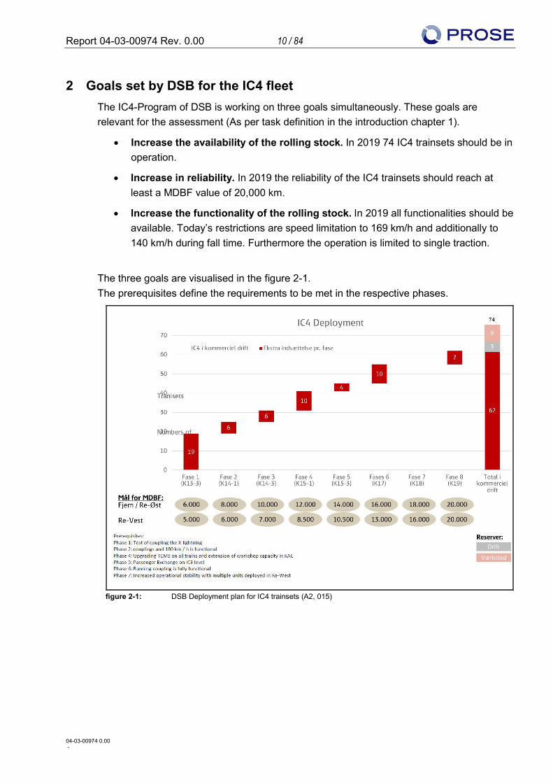
• Increase the availability of the rolling stock. In 2019 74 IC4 trainsets should be in operation.
• Increase in reliability. In 2019 the reliability of the IC4 trainsets should reach at least a MDBF value of 20,000 km.
• Increase the functionality of the rolling stock. In 2019 all functionalities should be available. Today’s restrictions are speed limitation to 169 km/h and additionally to 140 km/h during fall time. Furthermore the operation is limited to single traction.
The three goals are visualised in the figure 2-1. The prerequisites define the requirements to be met in the respective phases.
figure 2-1: DSB Deployment plan for IC4 trainsets (A2, 015)
Report 04-03-00974 Rev. 0.00 11 / 84
04-03-00974 0.00 -
3 Assessment Results This chapter summarised the result of the assessment. All details including the references to the documentation assessed are given in the corresponding appraisal chapters.
3.1 Current status IC4 trainsets The current availability requirement is to have 32 trainsets ready for operation twice a day. The total mileage of the fleet by end of October 2014 is 10.8 Mio km. In the period from the 1 January until 31 October 2014 the mileage of the fleet is 3.07 Mio km. The MDBF baseline calculated as average is 5,949 km between January and August 2014. Currently the trainsets are only operated in single operation (not in multiple operations as coupled units), and the maximum speed is limited. On a large number of trainsets a high amount of CFGs are already implemented. However, each trainset has its individual current status of CFGs implemented. Due to the poor reliability of the trainset and additional inspections, the maintenance efficiency is low. This leads to high operational costs.
3.2 Deployment plan IC4 trainsets The provided deployment plan as per figure 2-1 contains three dimensions: Availability, Reliability and Functionality. Following assessment results could be stated:
• Availability The final goal regarding availability is realistic. This requires keeping a clear focus on “Availability” in the workshop, as well as the required man-power. As a prerequisite for the future increase of availability, a positive development in trainset reliability is required. DSB has the required maintenance infrastructure as well as procedures in place to support this availability deployment.
• Reliability The final goal of 20,000 km MDBF regarding reliability is realistic in the long term in comparison with other vehicles and operators. Currently reliability is not given the same priority as availability and functionality. The MDBF baseline as an average of the fleet (January till August 2014) is 5,949 km for operation in regional and long distance traffic. The goal as per the deployment plan should be 7,260 km in January 2014 and increase to 9,077 km in August 2014. The total reliability improvement potential addressed is 2,473 km. This is not even sufficient to reach the goal defined for August 2014. However the MDBF of 13,687 km (A2, 406) only for November 2014 shows a positive tendency.
• Functionalities The final goals of the functionalities assessed are realistic from a technical point of view. Phase 2 (fixed couplings and 180 km/h) is delayed. Please note the completion of phase 2 will increase the operability of the trainset. All other goals are still achievable.
Report 04-03-00974 Rev. 0.00 12 / 84
04-03-00974 0.00 -
3.3 Additional measures recommended and their consequences DSB set up a deployment plan to define the goals. Measures have already been defined by DSB in the areas of organisation, operation, processes and for the improvement of technical solutions. The assessed measures are pointing in the right direction. However, additional measures in these areas are recommended. The recommended measures are addressed by the consequences from a technical, economical, operational and safety point of view.
3.3.1 Deployment plan
• Measures recommended o Plan to be maintained by owner o Goals must be monitored and communicated because they are partly
unknown as determined during interviews with DSB Operation and in workshop KAC
• Consequences
o None identified
3.3.2 Organisation
• Measures recommended o Set up a task force team on the power pack o Improve the reporting of failure messages by cross-functional teams
including drivers, engineering (hardware, software) and workshop staff; additionally these teams shall be used to reproduce errors in close collaboration
o Increase in experienced Reliability Improvement Team (RIT) and Engineering capacity by at least 10 FTE (this includes the task force and cross functional teams) to improve failure analysis and defining measures
o Increase of experienced Train Computer and Monitoring System (TCMS) Engineering capacity by at least 2 FTE
o Increase of the workshop staff by at least 40 FTE to speed up the CFG implementation
o Establish resource management for unexpected critical technical issues
• Consequences o Additional RIT and Engineering staff (This includes TCMS transfer team) of
12 FTE for next 3 years is required which amounts to approx. 43.2 Mio DKK o To speed up the CFG implementation additional maintenance staff of 40 FTE
for next 2 years is required which amounts to approx. 37.1 Mio DKK o Only consequences in the area of economics have been identified.
Report 04-03-00974 Rev. 0.00 13 / 84
04-03-00974 0.00 -
3.3.3 Operation
• Measures recommended o Five IC4 trainsets shall be designated to collect mileages. Therefore these
trainsets shall be prioritised for use in long distance traffic. The aim is to collect mileages within a short time period in order to obtain an indication of how the rest of the fleet will perform at a later stage.
• Consequences o None identified
3.3.4 Process
• Measures recommended o Follow the defined processes of IC4PT consequently and conscientiously,
especially: § Root cause analysis (RCA) § Definition of requirements (qualitative instead of quantitative) § Verification, validation and testing
o Implementation of the activity “compiling FMEA and validation plan” when a CFG is started
• Consequences o None identified
3.3.5 Improvement of technical solutions
• Measures recommended o Coupling multiple traction
§ The TCMS software version required for operation in fixed coupled double traction is not yet approved by the TS. Therefore the approval shall have the greatest focus within the IC4PT.
o Axle box housing § Completion of the RCA
o Brake system § Define a validation plan for the new blending parameters § Analyse the side effects of each modification, i.e. influence of the new
BCU-software version 1.16 on the performance of the Wheels Slide Protection System (WSP)
§ Deepen the knowledge of the system and the components with the goal to identify the potential for increased system reliability
o Power pack (PP) § RCA of current breakdowns of the crankshaft bearings in the engine
in order to identify the root cause of the damaged bearings, which may concern the entire fleet or not, and to define specific corrective actions.
Report 04-03-00974 Rev. 0.00 14 / 84
04-03-00974 0.00 -
§ Expand on design knowledge and repeat necessary validation (type) tests with the goal of assessing the risk of a design failure
• Consequences
o About < 1 Mio DKK for PP and axle box related non-recurring cost measures (From economical point of view)
• Possible consequences
o The current solutions on the power pack and the axle box housing are indicating weaknesses and these could lead to major design changes: § Design change leads to new engine, costings about 2 Mio DKK per
trainset § Design change leads to engine retrofit activities, costings about
800,000 DKK per trainset § Design change leads to new axle box housings, costings about
200,000 DKK per trainset
3.3.6 Financial overview
The balance as at today is based on the original project frame credit. Taking the above additional economic consequences into account, the following balance is given (74 trainsets considered):
• Balance as at today (Coupler refurbishment considered): 437 Mio DKK
• Balance with planned measures by DSB in 2019: 192.5 Mio DKK
• Balance with recommended measures in 2019: 111.2 Mio DKK
That means per trainset the remaining budget is 1.5 Mio DKK in 2019 with all recommendations considered. Taking into account the risks of a design change the following balance is given:
• Balance 2019 incl. PP bearing retrofit activities: 52.0 Mio DKK per trainset: 0.7 Mio DKK
• Balance 2019 incl. PP bearing & new axle box retrofit activities: 37.2 Mio DKK per trainset: 0.5 Mio DKK
• Balance 2019 incl. PP new motor & new axle box retrofit activities: -51.6 Mio DKK per trainset: -0.7 Mio DKK
This balance is based on the scope considered within this assessment. Therefore additional costs may occur.
Report 04-03-00974 Rev. 0.00 15 / 84
04-03-00974 0.00 -
3.4 Life time IC4/IC2 trainsets
Due to the delay in the procurement of the trainsets and therefore the shorter usable life cycle of the fleet, the investment made is poor. In the current situation the trains cannot be operated as expected but the investment to reach the deployment plan is known based on defined and recommended measures by this assessment. Hence DSB advised the development of the trainsets according to the deployment plan in order to allow an operation of the fleets on their natural lifecycle as long as the LCC performance is better than available alternatives.
Regardless of the amount of trainsets used and their duration of operation, the trainsets only have a value if the functionality and the reliability goals are reached.
3.5 Operational pattern During the assessment DSB asked for a recommendation about the future usage of the IC4 trainsets regarding interregional / regional. It is recommended that the IC4 trainsets are operated mainly in interregional traffic as specified (long distance train). This recommendation is based on the following facts:
• The IC4 trainset is a very heavy train with a 3.3 ton higher maximum axle load - 21.24 tons compared to available alternative DMU IC3
• Regional operation means shorter distance between stops and greater number of stops compared to interregional traffic, leading to
o Higher passenger exchange rates required
o Higher demands, especially for propulsion system, brake system and door system
o Higher wear on parts such as brake pads and wheels, resulting in additional maintenance
o Higher fuel consumption
• Lower MDBF figures
3.6 Differences compared to Atkins report Today is a completely different situation compared to October 2011, where the Atkins report was elaborated. The last trainsets were completed by the end of year 2013. Now the trainsets are in operation collecting more mileages and operational experience.
Due to several reasons such as poor workmanship, bad design and incomplete engineering, failures, especially of a dynamic nature resulting from service, still occur after a certain period of time. Due to this reason, differences relative to the conclusions of the Atkins report in 2011 were identified throughout our assessment in a number of specific topics.
Report 04-03-00974 Rev. 0.00 16 / 84
04-03-00974 0.00 -
Atkins concludes that the fundamental systems and major items of equipment fitted to IC4 trainsets are sound and are currently operating reliably. Unfortunately now this is not the case as identified during the technical risk assessment.
Report 04-03-00974 Rev. 0.00 17 / 84
04-03-00974 0.00 -
4 Current status of the IC4 fleet
4.1 IC4 fleet configuration The fleet consists of 82 trainsets, containing:
• 67 trainsets approved for operation (A1, 04)
• 5 trainsets are taken apart for spare parts, cannibalising (A1, 04)
• 74 trainsets shows the deployment plan for 2019 (A2, 015) The availability requirement is reached by 32 trainsets ready for operation twice a day.12 of the 32 trainsets are in passenger operation service, the others are serviced as operational reserve.
4.2 IC4 trainset configuration relating to CFG implementation The following observation has been made by assessing the trainset configurations (A02, 091). It contains the implementation status of all modifications and CFG which has been implemented. It reflects the following status by the 30 September 2014:
• The trainset 5655 has with 103 CFG the highest number of CFGs implemented
• CFGs have been implemented on 58 different IC4 trainsets in August and September 2014
• The fleet can be categorised into three groups:
o On 5 trainsets (5606, 5607, 5612, 5613 and 5614) only 7 CFGs are implemented. On all these trainsets, at least one CFG has been implemented in September 2014.
o On 6 trainsets, between 46 and 67 CFGs are implemented. Between May and August, on all trainsets at least one CFG has been implemented.
o On 71 trainsets, between 75 and 103 CFGs are implemented. Since April on all trainsets at least one CFG has been implemented.
Report 04-03-00974 Rev. 0.00 18 / 84
04-03-00974 0.00 -
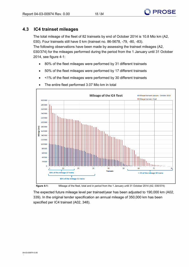
4.3 IC4 trainset mileages The total mileage of the fleet of 82 trainsets by end of October 2014 is 10.8 Mio km (A2, 030). Four trainsets still have 0 km (trainset no. 86-5678, -79, -80, -83). The following observations have been made by assessing the trainset mileages (A2, 030/374) for the mileages performed during the period from the 1 January until 31 October 2014, see figure 4-1:
• 80% of the fleet mileages were performed by 31 different trainsets
• 50% of the fleet mileages were performed by 17 different trainsets
• <1% of the fleet mileages were performed by 30 different trainsets
• The entire fleet performed 3.07 Mio km in total
figure 4-1: Mileage of the fleet, total and in period from the 1 January until 31 October 2014 (A2, 030/374)
The expected future mileage level per trainset/year has been adjusted to 190,000 km (A02, 339). In the original tender specification an annual mileage of 350,000 km has been specified per IC4 trainset (A02, 348).
Report 04-03-00974 Rev. 0.00 19 / 84
04-03-00974 0.00 -
4.4 IC4 trainset TCMS software status On the 7 November 2014, the implementation of the TC and GTW version 2.1 and the IDU software version 2.2a was introduce on the fleet. The IDU version 2.2a is a further development of the IDU version 2.1. The homologation of the version 2.1 is limited to single train operation (A2, 349). The version 2.2a has been classified by DSB as not significant, which has been confirmed by the National Safety Authority Trafikstyrelsen (TS). Therefore no dedicated homologation for the IDU version 2.2a is required. The TC, the GTW and IDU all have their own software. All three systems are collectively named TCMS (A2, 354).
Report 04-03-00974 Rev. 0.00 20 / 84
04-03-00974 0.00 -
5 Financial appraisal IC4 trainsets
5.1 Package Summary The allocated CAPEX will be sufficient to bring the majority of trainsets up to the specified level defined by the deployment plan with the measures defined by DSB and additionally recommended measures. However, there is a risk of exceeding this in the event that a new engine is required for the power pack or additional, non-assessed system parts requiring substantial modification. Due to late commission of the IC4 fleet the full usage period has been shortened from 25 to approx. 15 years. The current operational costs are reflecting the currently poor reliability of the IC4 fleet as well as the suboptimal inefficient maintenance. This will change when the MDBF improves.
5.2 Capital Expenditure / CAPEX This chapter compares the expected cost to achieve the goals set by DSB with the original project outline cost.
5.2.1 Current Situation
As per the provided financial overview (A02, 399) there is a balance of 475 Mio DKK, hence 6.4 Mio DKK per IC4 trainset equivalent to 74 trainsets left from the original project frame to complete the trainsets to specification level. 38 Mio DKK is allocated for the mechanical refurbishment of the coupler.
5.2.2 Cost Estimate to complete the trains
5.2.2.1 Measures already defined by DSB
The following costs are estimated based on the assessment to fulfil the goals of the deployment plan:
• IC4PT Management, Engineering and RIT with actual 30 FTE as per the current burn rate (A02, 339) for 2015 - 2019 (assumption) is estimated at a total of 180 Mio DKK
• Burn rate workshop with 40 FTE (assumption) as at the current hourly rate of 306 DKK (A02, 400) and 1515 h p.a. for 2015 – 2017 (assumption) is estimated at a total of 55.6 Mio DKK
• Material costs for smaller modifications estimated at 120,000 DKK (assumption) per IC4 trainset (8.88 Mio DKK for 74 trainsets)
Report 04-03-00974 Rev. 0.00 21 / 84
04-03-00974 0.00 -
The balance by 2019 with defined measures by DSB will be following: • Balance as at today: 475 Mio DKK • Cost for coupler modification: 38 DKK • Burn rate IC4PT Management, Engineering and RIT: 180 Mio DKK • Burn rate workshop: 55.6 Mio DKK • Material costs: 8.88.Mio DKK • Balance in 2019 with defined and planned measures by DSB: 192.5 Mio. DKK
5.2.2.2 Additional measures recommended
Based on the additional measures as recommended in chapters 7.2.3, 9.2 and 10.2 the following costs are estimated:
• Burn rate with 12 FTE of additional staff for IC4PT Engineering and RIT as per the current burn rate (A02, 339) for 2015 - 2017 is estimated at a total of 43.2 Mio DKK
• Burn rate with 40 FTE for additional workshop staff to implement CFGs as per the current hourly rate of 306 DKK and 1,515 h p.a. (A02, 400) for 2015 – 2016 is estimated at a total of 37.1 Mio DKK
• PP and axle box -> non-recurring cost measurement such as completing external RCA as well as function & type tests on test-bench estimate data total of < 1 Mio DKK
• Sum of additional recommended measures: 81.3 Mio DKK The balance by 2019 with additional measures as recommended:
• Balance in 2019 with defined and planned measures by DSB: 192.5 Mio DKK • Sum of additional recommended measures: 81.3 Mio DKK • Balance in 2019 with additional proposed measures: 111.2 Mio DKK • Balance per trainset (74 trainsets): 1.5 Mio DKK
Taking into account the risks of a design change, the following balance is given (See chapter 10.2.5):
• Balance 2019 incl. PP bearing retrofit activities: 52.0 Mio DKK per trainset: 0.7 Mio DKK
• Balance 2019 incl. PP bearing & new axle box retrofit activities: 37.2 Mio DKK per trainset: 0.5 Mio DKK
• Balance 2019 incl. PP new motor & new axle box retrofit activities: -51.6 Mio DKK per trainset: -0.7 Mio DKK
To reduce or eliminate the costs mentioned above the recommended power pack task force should be setup as soon as possible.
Report 04-03-00974 Rev. 0.00 22 / 84
04-03-00974 0.00 -
5.2.3 Usage period
As per the provided figures the original usage period was planned to 25 years (A2, 339/370). Due to late commission of the IC4 fleet the full usage period has been shortened from 25 years (2005 – 2030) to approx. 15 years (2015 – 2030) with the entire fleet performing the yearly mileages.
5.3 Operational Expenditure / OPEX This chapter compares the operation cost generated from the workshop activities with other fleets. As per the provided financial overview (A02, 339) the operational cost representing the maintenance efforts is in line with the hours spent (A02, 194). Due to the high level of unscheduled corrective maintenance (UCM) and the low amount of mileages driven, the operational cost for the IC4 fleet is compared to the other DSB fleet types very high. In the actual phase of the IC4PT programme these figures are not comparable. This means DSB needs to find a fast way to bring IC4 fleet out of this phase.
Report 04-03-00974 Rev. 0.00 23 / 84
04-03-00974 0.00 -
6 Appraisal “Organisation”
6.1 Summary In terms of the organisation the assessment reveals
• Well-functioning organisation and processes
• Improved collaboration required between IC4PT and DSB-S to enhance proper risk evaluation
• Additional man power resources should be provided
• Fault-prone, complex systems should be handled externally by special task forces
6.2 Assessment and Findings
6.2.1 Present Status
A huge change in the organisation was introduced at the beginning of this year 2014. That means IC4 Program Team (IC4PT ) is no longer a standalone organisation alongside to DSB Maintenance (DSB-M), but now integrated as an organisation in the DSB-M. DSB-M is highly focused on the handling of IC4 and IC2 trainsets like other trainsets in a normal maintenance organisation. Part of this reorganisation and therefore valid for the IC4PT is the independent DSB safety department (DSB-S) which ensures risk evaluation of every change.
Due to the high level of additional effort, especially with regard to fleet modifications by CFG an IC4PT organisation still exists including associated Quality Management System (QMS). It is important for the IC4PT to have its own QMS due to the complexity and quantity of the modifications. It requests not only a lot of human resources but also handling and agreement in regard to standards up to date respectively state of the art and applicable rules for “Authorisation for placing in service” or “Authorisation of types of trainset” with TS.
The independent DSB-S is carries out risk evaluations for each change relying upon comprehensive and proper information coming from IC4PT Engineering. Currently there is a resource-consuming bottleneck because for each CFG, precisely minor changes, the IC4PT Engineering has to prepare comprehensive documentation acc. to their process P10.10 (A2, 108). Based on that DSB-S is able to carry out risk evaluations and has to forward it to TS. On one hand this is currently requested by TS (A1, 38) and coms from the former organisation where the IC4PT was outstanding DSB-M and did the evaluations outside of a safety certificate. This procedure was continued by the independent DSB-S even after the organisational change at the beginning of this year. On the other hand it results from a previous loss of trust in relation to inaccurate or incomplete risk evaluations in the past like Death Train Management (DTM). That means if a minor modification is not considered to have an impact on safety and not to be significant the DSB shall submit the documentation of the evaluation for each CFG to TS against Article 12(3) of “Executive Order on the Approval of Railway Trainsets” (A2, 092).
Report 04-03-00974 Rev. 0.00 24 / 84
04-03-00974 0.00 -
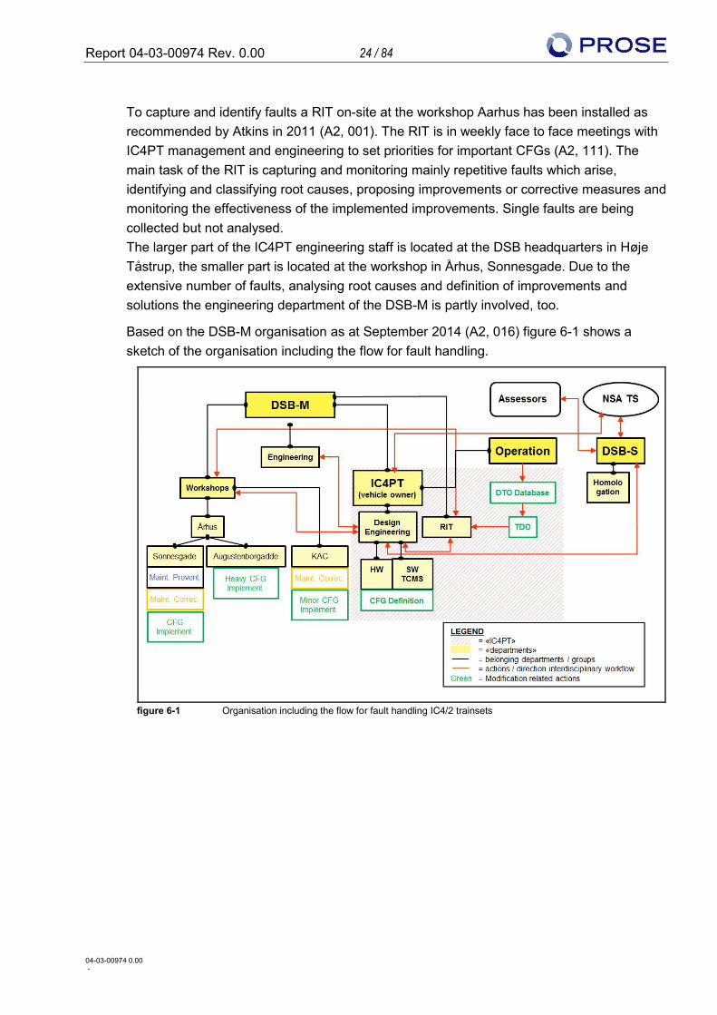
To capture and identify faults a RIT on-site at the workshop Aarhus has been installed as recommended by Atkins in 2011 (A2, 001). The RIT is in weekly face to face meetings with IC4PT management and engineering to set priorities for important CFGs (A2, 111). The main task of the RIT is capturing and monitoring mainly repetitive faults which arise, identifying and classifying root causes, proposing improvements or corrective measures and monitoring the effectiveness of the implemented improvements. Single faults are being collected but not analysed. The larger part of the IC4PT engineering staff is located at the DSB headquarters in Høje Tåstrup, the smaller part is located at the workshop in Århus, Sonnesgade. Due to the extensive number of faults, analysing root causes and definition of improvements and solutions the engineering department of the DSB-M is partly involved, too.
Based on the DSB-M organisation as at September 2014 (A2, 016) figure 6-1 shows a sketch of the organisation including the flow for fault handling.
figure 6-1 Organisation including the flow for fault handling IC4/2 trainsets
Report 04-03-00974 Rev. 0.00 25 / 84
04-03-00974 0.00 -
6.2.2 Findings and recommendation
All members of the IC4PT met or interviewed have been enthusiastic about the project.
The number of resources in terms of competent experts especially in system engineering is insufficient.
The already enhanced amount of resource within the RIT is still insufficient to achieve the necessary reliability growth defined by the deployment plan. Recommendations:
• Improve the collaboration between IC4PT and DSB-S to enhance proper risk evaluation
• Improve the collaboration between IC4PT engineering and workshops which are located at different places
• Additional human resources (experienced driver, system engineers) to reproduce single-faults
• In the event of new errors appearing on complex systems it is recommended that these are handled by special task forces consisting of experienced experts and system engineers
Report 04-03-00974 Rev. 0.00 26 / 84
04-03-00974 0.00 -
7 Appraisal “Quality management”
7.1 Package Summary In terms of the quality management the assessment reveals:
• The CFG processes of the IC4PT QMS is observed as a state-of-the-art QMS for rolling stock
• Follow the defined CFG hardware process P10.10 (A2, 108) of the IC4PT QMS consequently and conscientiously, especially
o Root cause analysis o Definition of requirements (qualitative instead of quantitative) o Verification, validation and testing
• Implementation of the activity “compiling FMEA and validation plan” when a CFG is started in the CFG process P10.10 (A2, 108)
• Technical knowledge, adequate planning and processes as well as an adequate level of documentation for software modifications carried out so far, with specific reference to TCMS, have been demonstrated
• DSB might want to further improve the know-how gained through the software transfer team for modifications to be entirely carried out at DSB
• It is recommended that an experienced SW validator is placed within the SW TCMS development team for modifications to be entirely carried out at DSB
7.2 Assessment and Findings
7.2.1 Introduction
There are two different QMSs affecting the IC4 fleet. The DSB-M global QMS certified according to ISO 9001:2008 (A3) and the non-certified QMS of the IC4PT. Due to the reorganisation and since the QMS of the IC4PT is much better than the global QMS of DSB-M (especially in the case of handling modifications) current processes are transferring from the QMS of the IC4PT into the certified global QMS of DSB-M. The aim of the assessment was the analysis and evaluation of the processes and quality management system of both QMSs. The focus has been set to the QMS of the IC4PT especially in regards to the handling of ongoing CFG-related to hardware and software modifications.
Report 04-03-00974 Rev. 0.00 27 / 84
04-03-00974 0.00 -
7.2.2 Global QMS DSB Maintenance
7.2.2.1 Practice
PROSE assessed the global DSB-M QMS during an interview with DSB-M quality (A1, 35). The focus was set to:
• The quality manual • The compliance and application of their processes in DSB-M • Process metrics • Results of external audits • Supplier management
A further task of the interview was the handling of two different QMS (global QMS & IC4-QMS).
7.2.2.2 Impression
The DSB-M QMS is certified according to ISO 9001:2008 (A3), OHSAS 18001:2007 (A4) and ISO 14001:2004 (A5). In general, DSB-M is on a good path. They changed the usability of their quality manual as a consequence of poor application of their processes. The result of that change was better compliance with them and comprehension of them. It may be mentioned positively that the quality manual is clearly laid out in workshop location.
7.2.2.3 Findings and recommendations
Ratios are not collected in all processes but DSB-M could disclose their most important process metrics (e.g. MDBF). These will be measured regularly. In June 2014 DSB-M Quality was assessed by a new certifying body for their ISO 9001:2008 (A3) certification. As a result, DSB-M received five obligations and eight suggestions / hints. However, no aspect was so critical that DSB-M lost the certification, for details see (A2, 403). In the past, DSB-M executed only a few supplier audits. In 2014 already two supplier audits were performed. DSB-M Quality would like to increase the number of supplier audits. But in general, it seems to be unclear how to handle the quality control of supplier parts. Several CFG packages have been engineered by the DSB-M engineering. Neither the IC4-QMS nor the global QMS defines how to handle this interdisciplinary exchange between the different departments as well as between the different quality management systems. Recommendations:
• DSB-M Quality should provide requirements regarding the evaluation of suppliers and the quality control of supplier parts in order to prevent failures on the (IC4-) trainsets due to insufficient quality of any parts.
• DSB-M Quality should define processes to manage CFGs which were engineered by the DSB-M engineering for the IC4PT.
Report 04-03-00974 Rev. 0.00 28 / 84
04-03-00974 0.00 -
7.2.3 IC4PT QMS - Software TCMS
7.2.3.1 Practice
The aim was the analysis and evaluation of processes and quality management for the currently performed software modifications, with an outlook to the challenges and opportunities associated with the introduction of software development at DSB (A2, 404). A two-day meeting has been held at DSB including specific interviews with the DSB personnel in charge for the TCMS. The focus was set on:
• The generic overview of the project structure, organisation and development processes of the software modifications of the TCMS
• The applied processes related to the randomly chosen SW package 2.1
• The application of the specific requirements from the CSM Regulation, CENELEC standards EN50126:1999 (A6) and EN50128:2011 (A7)
Additionally, spot checks on the processes for the SW package MU4 have been performed.
7.2.3.2 Impression
DSB have demonstrated
• Technical knowledge, adequate planning and processes as well as an adequate level of documentation to successfully manage potential safety risks related to the TCMS modifications according to the European legislation, namely the Common Safety Measures (CSM-RA, European Regulation 402/2013).
• Adequate planning and processes as well as an adequate level of documentation to ensure that the TCMS modifications fulfil DSB requirements
• TCMS development process, including the phases under DSB suppliers and their sub supplier responsibility, compliant with the relevant technical standards, namely EN50126 (A6) and EN50128 (A7).
• Technical and procedural knowledge to carry out the SW modifications according to the relevant technical standards is ensured by AB and by their sub-supplier Tecnologie nelle Reti e nei Sistemi (TRS)
Regarding future modifications to be entirely carried out at DSB:
• The fulfilment of the technical requisites from EN50128 (A7) poses different challenges to DSB in the fields of know-how, human resources, SW development processes and SW assessment
• DSB is aware of the most critical above mentioned challenges and have consequently already formulated a project plan to mitigate the impact of the identified challenges on the project
Report 04-03-00974 Rev. 0.00 29 / 84
04-03-00974 0.00 -
7.2.3.3 Findings and recommendations
DSB might want to further improve the know-how gained through the transfer team to fill the current gaps in the compliance of TRS processes with some requirements from EN50128 (A7), as identified by Lloyd’s audit report (A2, 365). The improvement of the processes should be documented e.g. in the SW Quality assurance Plan and agreed with the assessor. A further challenge to the project is identified in the current lack of an experienced SW validator within the TCMS project team, familiar with the validation tasks as specified by EN50128 (A7) for SIL2 functions and specifically experienced to critically judge the TCMS development, its results and the impact of potential issues / shortcomings identified in the processes or in the SW itself. Since validation activities have not been part of the transfer team members’ training, it is recommended that an SW validator is placed in the SW development team. DSB IC4PT is aware that a replacement experienced in the SW development according to EN50128 (A7) could be needed should any transfer team member no longer work on the TCMS project any longer. With reference to the interfaces with third party companies, the potential risk of delay and extra costs associated to the TCMS development could have been further reduced by following the processes defined in the DSB quality management system, namely the procedure P11 (A2, 109), without the deviations applied to the currently implemented TCMS modifications. Specifically, for future projects involving outsourced SW development, DSB might desire to exhaustively define the requirements, including the safety requirements, before finalizing a SW development contract with a third party company.
Report 04-03-00974 Rev. 0.00 30 / 84
04-03-00974 0.00 -
7.2.4 IC4PT QMS – Hardware
7.2.4.1 Practice
IC4PT CFG process P10.10 (A2, 108) has been reviewed on the basis of a closed and an ongoing modification.
7.2.4.2 Impression
The reviewed process P10.10 seems to work well for the settlement of CFGs. The sequence of the different process steps is useful. The responsibilities within each CFG are regulated. The process is used for significant and non-significant modifications. This process covers minor and major modifications. In the event that the CFG is not significant, steps 4.5 and 4.6 won’t be executed. These steps require an external assessor, which has to be approved by TS and the execution of a hazard workshop. All CFGs are managed by a software based on a database. By using this software the CFGs can be controlled and monitored (e.g. by their status, costs or validation steps) by the CFG project manager. Given that the usage of the software started in spring 2014, the completeness of the data is not given yet. This software has the possibility not only to control the CFGs but also to schedule the resources for implementation in advance and to set up a reliability improvement plan.
7.2.4.3 Findings and recommendations
The presented and reviewed CFG no. CFG-DSB0133 (frost evacuation water toilet system, with no safety impact or significance) was settled completely according to the guidelines of the process. All required documents are registered, filled out and improvements take effect in the workshop concerned. The CFG has been released according to the staff matrix. A check of a different ongoing CFG no. CFG-DSB0274 (new blending philosophy of the BCU software 1.16 according to chapter 10.2.2.4) discovered that not all CFGs are executed according to the process and performed as the example mentioned above. In the process P10.10, the function of an “Integrator” is foreseen. Its function is among others to perform a validation of the defined design solution. Nevertheless a FMEA and a reasonable validation plan should be performed during launching a CFG for major modifications. This shall guarantee a proper overview before starting up the design of a modification. Recommendations:
• The performed work shall follow the processes consequently • Implementation of the activity “compiling FMEA and validation plan” in step 4.2 of
the hardware process P10.10
Report 04-03-00974 Rev. 0.00 31 / 84
04-03-00974 0.00 -
8 Appraisal “Workshop Performance”
8.1 Package Summary In terms of the workshop performance the assessment reveals:
• The workshops Sonnesgade and Augustenborggade in Aarhus, as well as Kastrup Copenhagen Airport are well equipped and fit for purpose.
• The capacity of the workshops at Sonnesgade and Augustenborggade are not reached by any means. Both sites can double the amount of work hours with a preparation/ramp-up period of approx. 6 months.
• The workshop management including the clear priority setting, the use of IT to support the process, including the transparent visualization of activity (A02, 195), the work documentation including the trainset configuration (A02, 091) are on a best-in-class level
• The low reliability reflected in the MDBF KPI (A02, 004) of the IC4 fleet generates a high number of unplanned repairs in the workshop. This prevents the workshop from sustainable activity planning and efficiency.
• In comparison with a reference trainset the hours spent for maintenance of IC4 trainsets is 5.3 times higher. But this reflects a temporary situation which will change.
• Due to the poor reliability of the trainset and additional inspections, the maintenance efficiency is low. This leads to high operational costs.
8.2 Assessment and Findings
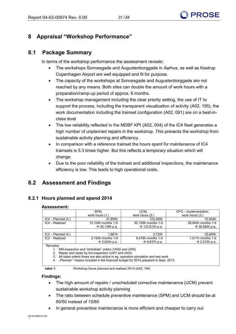
8.2.1 Hours planned and spend 2014
Assessment: SPM,
work hours (1.) UCM,
work hours (2.) CFG – Implementation,
work hours (3.) IC4 – Planned (4.) 31,855h 123,265h 70,404h IC4 – Realized 15,104h months 1-9
à 20,138h p.a. 92,109h months 1-9 à 122,812h p.a.
28,945h months 1-9 à 38,593h p.a.
IC2 – Planned (4.) 1,861h 3,720h 33,850h IC2 – Realized 2,193h months 1-9
à 2,924h p.a. 6,478h months 1-9
à 8,637h p.a. 1,511h months 1-9
à 2,015h p.a. Remarks:
1. KM-inspection and “stribeliste” orders (Vh02 and vh05) 2. Repair and repair by km-inspection (vh01 and vh03) 3. All sales orders those are also active in eg. operation simulation and test work 4. „Planned " means included in the financial budget for 2014 prepared in Sept. 2013.
table 1: Workshop hours planned and realised 2014 (A02, 194)
Findings: • The high amount of repairs / unscheduled corrective maintenance (UCM) prevent
sustainable workshop activity planning • The ratio between schedule preventive maintenance (SPM) and UCM should be at
50/50 instead of 15/85 • In general preventive maintenance is more efficient and cheaper to carry out
Report 04-03-00974 Rev. 0.00 32 / 84
04-03-00974 0.00 -
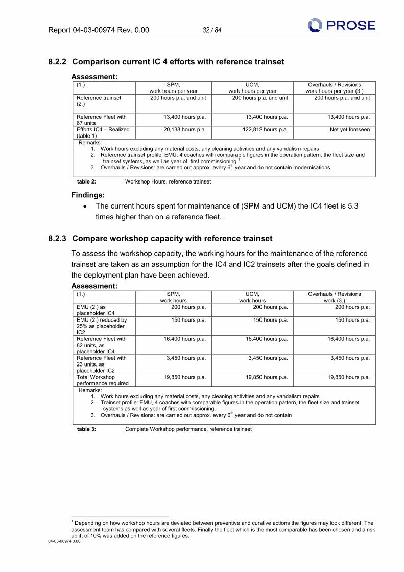
8.2.2 Comparison current IC 4 efforts with reference trainset
Assessment: (1.) SPM,
work hours per year UCM,
work hours per year Overhauls / Revisions
work hours per year (3.) Reference trainset (2.)
200 hours p.a. and unit 200 hours p.a. and unit 200 hours p.a. and unit
Reference Fleet with 67 units
13,400 hours p.a. 13,400 hours p.a. 13,400 hours p.a.
Efforts IC4 – Realized (table 1)
20,138 hours p.a. 122,812 hours p.a. Net yet foreseen
Remarks: 1. Work hours excluding any material costs, any cleaning activities and any vandalism repairs 2. Reference trainset profile: EMU, 4 coaches with comparable figures in the operation pattern, the fleet size and
trainset systems, as well as year of first commissioning.1 3. Overhauls / Revisions: are carried out approx. every 6th year and do not contain modernisations
table 2: Workshop Hours, reference trainset
Findings: • The current hours spent for maintenance of (SPM and UCM) the IC4 fleet is 5.3
times higher than on a reference fleet.
8.2.3 Compare workshop capacity with reference trainset
To assess the workshop capacity, the working hours for the maintenance of the reference trainset are taken as an assumption for the IC4 and IC2 trainsets after the goals defined in the deployment plan have been achieved. Assessment:
(1.) SPM, work hours
UCM, work hours
Overhauls / Revisions work (3.)
EMU (2.) as placeholder IC4
200 hours p.a. 200 hours p.a. 200 hours p.a.
EMU (2.) reduced by 25% as placeholder IC2
150 hours p.a. 150 hours p.a. 150 hours p.a.
Reference Fleet with 82 units, as placeholder IC4
16,400 hours p.a. 16,400 hours p.a. 16,400 hours p.a.
Reference Fleet with 23 units, as placeholder IC2
3,450 hours p.a. 3,450 hours p.a. 3,450 hours p.a.
Total Workshop performance required
19,850 hours p.a. 19,850 hours p.a. 19,850 hours p.a.
Remarks: 1. Work hours excluding any material costs, any cleaning activities and any vandalism repairs 2. Trainset profile: EMU, 4 coaches with comparable figures in the operation pattern, the fleet size and trainset
systems as well as year of first commissioning. 3. Overhauls / Revisions: are carried out approx. every 6th year and do not contain
table 3: Complete Workshop performance, reference trainset
1 Depending on how workshop hours are deviated between preventive and curative actions the figures may look different. The assessment team has compared with several fleets. Finally the fleet which is the most comparable has been chosen and a risk uplift of 10% was added on the reference figures.
Report 04-03-00974 Rev. 0.00 33 / 84
04-03-00974 0.00 -
Findings: • The available workshop capacities are sufficient to maintain the whole IC4 and IC2
fleet, once the trainsets are performing on the expected reliability level (MDBF>20,000 km). However due to operational aspects it might be better to carry out maintenance at multiple sites in order to reduce unnecessary trainset transports.
• The current maintenance handbook for the IC4 (A02, 197) holds for the Mega meter (Mm) inspections 15, 30, 45, 60, 75, 90, 105, 120, 135, 150, 165, 180Mm a total of 339 hours. Since the maintenance handbook is just about to be optimised the number of hours from the maintenance handbook of the IC4 trainset compared to the number of preventive hours for the reference trainset might be in line.
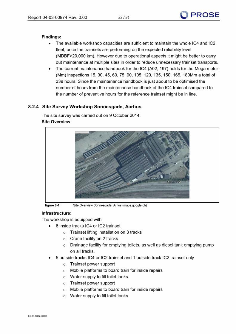
8.2.4 Site Survey Workshop Sonnesgade, Aarhus
The site survey was carried out on 9 October 2014. Site Overview:
figure 8-1: Site Overview Sonnesgade, Arhus (maps.google.ch)
Infrastructure: The workshop is equipped with:
• 6 inside tracks IC4 or IC2 trainset o Trainset lifting installation on 3 tracks o Crane facility on 2 tracks o Drainage facility for emptying toilets, as well as diesel tank emptying pump
on all tracks. • 5 outside tracks IC4 or IC2 trainset and 1 outside track IC2 trainset only
o Trainset power support o Mobile platforms to board train for inside repairs o Water supply to fill toilet tanks o Trainset power support o Mobile platforms to board train for inside repairs o Water supply to fill toilet tanks
Report 04-03-00974 Rev. 0.00 34 / 84
04-03-00974 0.00 -
Planning: • There is planning done outside of the workshop for the mega mileage inspections • There is weekly planning (A02, 196) in the workshop done including what, where
and whom (track, team and work content) • There is daily planning done including the same content as the weekly plan
Shift Model: • The current shift plan has three shifts. The morning shift 05:00-13:00 with a staffing
level of between 30-50 craftsmen, the afternoon shift with a staffing level of 6 and night shift with a staffing level of 3 craftsmen (A2, 195).
Findings: • The workshop Sonnesgade fits its purpose but the facility capacity not reached by
any means. If required, the workshop could produce double the amount of hours with a preparation/ramp up period of approx. 6 months
• Processes, IT support, work documentation, transparency, trainset configuration management are on a best-in-class level
• Integration of workshop management, trainset maintenance, component overhauling, spare part management is closed and provides a good basis for common identification and improvement of the maintenance
• Once the suboptimal and time-consuming maintenance tasks (ex. frequent inspections of wheel profile, exchange of half used wheels due to not adjustable power pack software, etc.) can be eliminated, approx. 40% of the current work hours can be spent on more useful maintenance
• The nightshift is primarily used to do nursing during takeover of trainsets by the drivers. It is understood that this cost-intensive action is actually necessary to reach the availability goal.
Additional observations: • During the workshop survey trainset have not been moved during the shift. Hence
once the maintenance was finished on one trainset it was still parked inside. One reason for this is a suboptimal situation in the trainset disposition, meaning due to the parked trainset outside just in front of the door the trainset shunting requires more than one driver. In addition the workshop personnel are limited in driving the trains in and out of site. The best solution would be one separate drive out track for two inside tracks in order to drive out without moving. Alternatively trains with a level of work which does not fill out the full shift should not been blocked with a trainset on the outside track.
• The trainset lifting and the driving / parking of trainsets cannot be performed in an efficient way due to limitations in who is allowed to perform these special tasks.
Report 04-03-00974 Rev. 0.00 35 / 84
04-03-00974 0.00 -
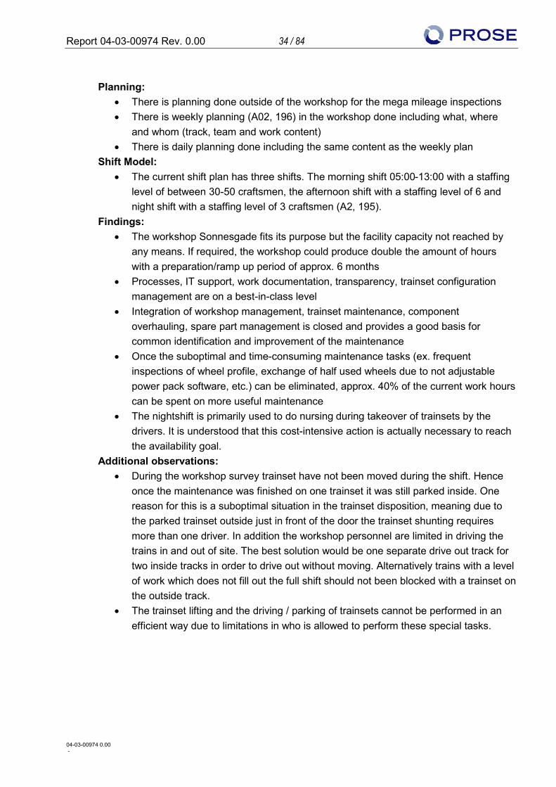
8.2.5 Site Survey Workshop Augustenborggade, Aarhus
The site survey was carried out on 10 October 2014. Site Overview:
figure 8-2: Site Overview Augustenborggade, Arhus (maps.google.ch)
Infrastructure: The workshop is equipped with:
• 2 inside tracks IC4 or IC2, the installations are prepared to do the CFGs currently in implementation phase and will be adopted according to the upcoming CFGs (ex. Lifting facilities).
• 1 inside track IC4 or IC2 in the “preparation for painting” hall • 3 outside tracks IC4 or IC2
Planning: • There is planning done (A02, 192) outside of the workshop for the major/focus CFGs
on a weekly basis • Currently 60 % of the performed work is CFG’s (planned), 40% are unplanned
repairs • After leaving Augustenborggade the trainsets are always sent to Sonnesgade for the
remaining maintenance tasks and preparation for handover to operations Shift Model:
• The workshop is operated on a one shift model beginning at 05:30 with a meeting at 07:45. It is based on 37h per week with a 1h preparation block.
Findings: • The workshop Augustenborggade fits the purpose but the facility capacity is not
reached by any means. If required, the workshop can produce double the amount of hours with a preparation/ramp-up period of approx. 6 months
• Although the building structure is older and more narrow, the workshop is well equipped and fits the purpose.
Report 04-03-00974 Rev. 0.00 36 / 84
04-03-00974 0.00 -
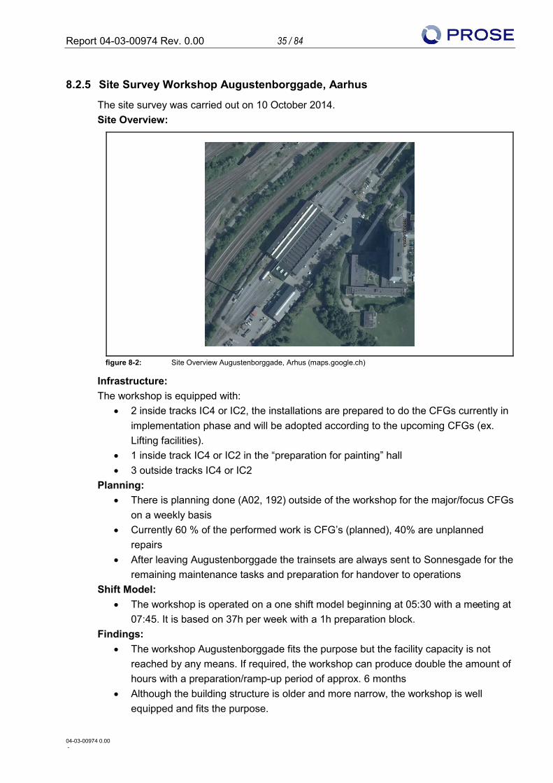
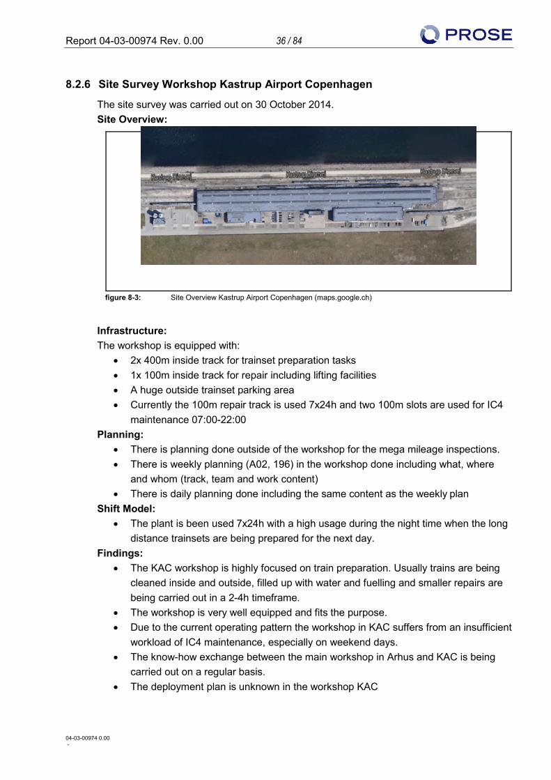
8.2.6 Site Survey Workshop Kastrup Airport Copenhagen
The site survey was carried out on 30 October 2014. Site Overview:
figure 8-3: Site Overview Kastrup Airport Copenhagen (maps.google.ch)
Infrastructure: The workshop is equipped with:
• 2x 400m inside track for trainset preparation tasks • 1x 100m inside track for repair including lifting facilities • A huge outside trainset parking area • Currently the 100m repair track is used 7x24h and two 100m slots are used for IC4
maintenance 07:00-22:00 Planning:
• There is planning done outside of the workshop for the mega mileage inspections. • There is weekly planning (A02, 196) in the workshop done including what, where
and whom (track, team and work content) • There is daily planning done including the same content as the weekly plan
Shift Model: • The plant is been used 7x24h with a high usage during the night time when the long
distance trainsets are being prepared for the next day. Findings:
• The KAC workshop is highly focused on train preparation. Usually trains are being cleaned inside and outside, filled up with water and fuelling and smaller repairs are being carried out in a 2-4h timeframe.
• The workshop is very well equipped and fits the purpose. • Due to the current operating pattern the workshop in KAC suffers from an insufficient
workload of IC4 maintenance, especially on weekend days. • The know-how exchange between the main workshop in Arhus and KAC is being
carried out on a regular basis. • The deployment plan is unknown in the workshop KAC
Report 04-03-00974 Rev. 0.00 37 / 84
04-03-00974 0.00 -
9 Appraisal “MDBF Improvement and goals”
9.1 Package Summary Regarding the MDBF improvements and goals the assessment shows:
• The MDBF goals set by the deployment plan (A2, 015) are realistic in comparison with other vehicles and operators
• Currently the MDBF shown on a monthly basis (A2, 015) is below the goal set. This is due to the current focus of the IC4 program which is set to eliminate design errors and enable train functionality as per specification level as well as the workshop which has a clear focus on availability of trainsets. However the MDBF of 13,687 km (A2, 406) only for November 2014 shows a positive tendency.
• The total MDBF improvement potential addressed in CFGs and RIT reports is 2,473 km (A2, 161) which is much too low.
• Hence it is recommended that the engineering and RIT expand as well as double up on the number of crew implementing CFGs.
• To improve the reporting of failure messages, cross-functional teams including drivers, engineering (hardware, software) and workshop staff shall be established.
• After the known design errors are eliminated, the train functionalities are enabled. Then the focus for the IC4 program needs to be on the improvement of the reliability, hence MDBF. For released CFGs the rollout needs to be planned and implemented as fast as possible within the limits set by the workshop capacity in order to navigate out of the current situation fast.
9.2 Assessment and Findings • By end of the year 2014 about one third of the total mileage of the fleet has been
performed within 2014 which reflects an increased operation performance (A2, 030). • It is likely that by the end of the year 2014 about 20 trainsets will collect 100,000 km
each (A2, 030). This basis is solid enough for key performance indicators (KPI). • The MDBF goals set by the deployment plan are realistic compared to other fleet
and operators (A2, 015). • Currently the reliability improvements are not as much of a priority as the availability
(Focus of the workshop) and the improvement of the functionalities. (Focus of the IC4PT).
• Since April 2014 the reliability improvement goals have not been reached. There is no tendency in the monthly report of MDBF (A2, 111) to achieve the goals set in the deployment plan.
• The MDBF baseline calculated by RIT as average of the fleet (January till August 2014) is 5,949 km (A2, 161) for operation in regional and long distance traffic. The MDBF goal as per the deployment plan should be 7,260 km in January 2014 and increase to 9,077 km in August 2014 (A2, 015).
• The MDBF reached for November 2014 is 13,687 km (A2, 406).
Report 04-03-00974 Rev. 0.00 38 / 84
04-03-00974 0.00 -
• The current improvement potential addressed by the RIT is 2,473 km. This reflects all known CFG’s and RIT reports (A2, 161).
• Currently there are two implementation methods for CFGs: o Packages, currently “coupling” on two trainsets per week scheduled in
Augustenborggade (A2, 192) o During regular maintenance
• The IC4 program is focusing on “Top 10” CFGs during design and implementation phase (A2, 111)
• Since the potential addressed (A2, 161) is not sufficient and the design and implementation is in some cases rather slow, both areas need to be developed. It is most important to get out of this critical situation fast. Hence enlargement of the engineering and RIT is recommended as well as doubling up the crew implementing CFGs.
• To improve the reporting of failure messages, cross-functional teams including drivers, engineering (hardware, software) and workshop staff shall be established. This is to ensure high quality of failure messages and close cooperation in the investigation and solution finding.
• After successful validation, and only then, CFGs need to be rolled out over the entire fleet as fast as possible in order to earn the savings and release the workshop from UCM.
Although five IC4 trainsets are taken apart for spare parts, the goal of the deployment plan to have 74 trainsets in operation in 2019 is not affected. Furthermore, today no decision has to be made, if in the end all 82 trainsets shall be taken into operation. This decision can be made at a later stage, when the financial basis (CAPEX, OPEX) is sustainable. Since April 2014 on all trainsets at least one CFG has been implemented; in August and September 2014 at least one CFG on 58 trainsets. On a large number of trainsets a high amount of CFGs are already implemented. Nevertheless no time schedule for the CFG implementation on the fleet exists. Excluded from this statement is the gaiter package, where an implementation plan is in place for the first 20 trainsets. This leads to the fact, that each trainset has its individual current status of CFGs implemented as well as a reactive implementation; reactive in the sense that CFGs are implemented when the trainsets are in the workshop. However the rollout of CFGs is under control due to a transparent configuration management. Due to the individual trainset configuration status, error finding and RCA is more difficult and time consuming. Therefore it is recommended that implementation is increased in order that as soon as a CFG is released for implementation a rollout plan is defined and the implementation on the entire fleet is performed within a short time-frame.
Report 04-03-00974 Rev. 0.00 39 / 84
04-03-00974 0.00 -
10 Appraisal “Technical risk assessment of main functions”
10.1 Package Summary This technical assessment does cover all currently addressed issues, but future issues could occur (e.g. fatigue failures in structures which could occur at higher mileages). Due to reasonable suspicion also other systems fitted to trainsets might be incompletely engineered. Regarding the Technical risk assessment on main functions the assessment shows:
• Coupling multiple traction o The TCMS software version required for operation in fixed coupled double
traction is not yet approved by the TS. Therefore the approval shall have the highest intension within the IC4PT.
o Front gaiter modification seems to be ok but is not fully validated, however the not performed tests will not prevent from fixed double traction.
o Additional measures can’t be excluded, because not all modification on the coupling system are well tested
o The physical modification of 20 trains for be able to operate in fixed coupled double traction by the 14 December 2014 are on time
• Brake
o Two major failures in the system design where revealed during the investigation after Marslev event
o The measures defined and implemented by DSB seem adapted in order to get rid of the speed limitation. The results of the validation tests are not known at the edition date of this report.
o A validation plan of the new blending parameters in the BCU software has to be set up.
o The brake system of the IC4/2 trainsets is complex with numerous monitoring equipment and redundancies. A deep investigation of the system is advised with the goal to identify the possibilities to increase the reliability of the system.
Report 04-03-00974 Rev. 0.00 40 / 84
04-03-00974 0.00 -
• Axle box housing:
o Insufficient RCA based only on statistic
o Measures defined by DSB are pointing in the right direction, but there is a risk due to the insufficient RCA that the measures are not sufficient. This may affect also the safety-relevant upper part of axle box housing
o FE Analysis did not considered the current higher weight balance (difference > 1 tons per axle)
o Lowering the rail guard to avoid collisions with objects is recommended
o Wheel maintenance manual should consider the EN15313 to control the wheel out-of-roundness
• Power Pack
o 25 CFGs have been defined on the power pack. 4 of them are critical.
o Since some of the actual issues can have quickly drastic consequences it is recommended to setup a task force that will be able to investigate RCA of current break downs of crankshaft in the engine and implement solutions in a short time.
o A detailed technical assessment of the power pack is recommended. For the safe development of the program it is mandatory to strengthen the technical basis of the power pack by detecting possible failures before they appear during operation.
o 5 IC4 trainsets shall be designated to collect mileages. Therefore this trainsets shall be used in operation prioritized. The aim is to collect mileages in a short time to have an indication how the rest of the fleet will perform at later stage.
10.2 Assessment and Findings
10.2.1 Coupling multiple traction
10.2.1.1 Introduction
According to the deployment plan the functionality of operation with coupled trains shall be achieved in two steps (A2, 015):
• Running with fixed coupled IC4 trainsets first quarter 2014 (phase 2) • Running with coupling/decoupling in operation first quarter 2017 (phase 6)
Currently DSB Operation (DSB-O) plans to operate one trainset with two IC4 trainsets fixed coupled in December 2014 (A1, 22). According to DSB-M 20 trainsets shall be upgraded with the coupler package by December 2014 (A2, 111).
Report 04-03-00974 Rev. 0.00 41 / 84
04-03-00974 0.00 -
Based on these the overdue date for running with fixed coupled IC4 trainsets is seen as replaced by the goal to have 20 trainset ready for fixed coupled operation in December 2014. It is therefore recommended to update the deployment plan. Despite the physical modifications of the coupler itself, also the TCMS and the BCU software needs to be updated to run fixed coupled in operation. The defined measures for physical modifications of the coupler are defined in different CFGs:
• CFG0113: Modification on RECO Antenna • CFG0161: Modification of cable support • CFG0165: Adjusting of pressure switch • CFG0167: Front gaiter • CFG0168: Front gaiter, electrical change • CFG0169: Decoupling electrical coupler • CFG0280: Coupler overhaul (Includes exchange of the bearing (A2, 188))
The focus of this technical assessment has been set to the critical CFGs:
• CFG0113: Modification on the RECO Antenna (A2, 329) • CFG0167: Front gaiter (A2, 332) • CFG0168: Front gaiter, electrical change (A2, 333) • CFG0169: Decoupling electrical coupler (A2, 334) • CFG0280: Coupler overhaul (A1, 27)
In this list not considered are the modifications of the TC and BCU software which are also required for operating in multiple traction.
10.2.1.2 Critical CFGs
10.2.1.2.1 Modification on the RECO Antenna - CFG-DSB0113
A retracted coupler of a not occupied trainset can be extracted from the occupied trainset over the remote control system RECO by the train driver. This system didn’t work as specified, because the communication between the two trainsets to be coupled was disturbed. Tests performed by Blueprint have shown that the signal of the RECO antenna was disturbed by the windshield (A2, 184), because the antenna was located on the upper part of the cab behind the windshield. Based on this finding, the RECO antenna has been replaced to a position in the front of the cab. Additionally a different antenna type has been defined.
After this modification, no type test has been performed with the new RECO antenna placed at the new position. With considering the test with the old RECO antenna moved to a location close to the currently used position, which shows the functionality even for a distance between the trains of 50m and the tests performed by Blueprint (with a different antenna type), which shows an increase of the signal of about 20dB between the old and
Report 04-03-00974 Rev. 0.00 42 / 84
04-03-00974 0.00 -
the new location, the functionality of the RECO system can be seen as verified (A2, 183/184/191). The good function of the remote control system with a distance between the trains of more than 20 meters could be witnessed during the coupling tests performed on the 9 October 2014 (A1, 29).
10.2.1.2.2 Front gaiter - CFG-DSB0167 / CFG-DSB0168
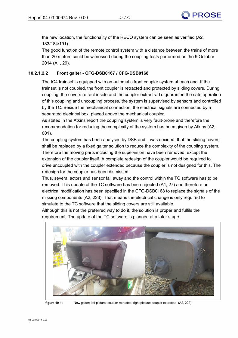
The IC4 trainset is equipped with an automatic front coupler system at each end. If the trainset is not coupled, the front coupler is retracted and protected by sliding covers. During coupling, the covers retract inside and the coupler extracts. To guarantee the safe operation of this coupling and uncoupling process, the system is supervised by sensors and controlled by the TC. Beside the mechanical connection, the electrical signals are connected by a separated electrical box, placed above the mechanical coupler. As stated in the Atkins report the coupling system is very fault-prone and therefore the recommendation for reducing the complexity of the system has been given by Atkins (A2, 001). The coupling system has been analysed by DSB and it was decided, that the sliding covers shall be replaced by a fixed gaiter solution to reduce the complexity of the coupling system. Therefore the moving parts including the supervision have been removed, except the extension of the coupler itself. A complete redesign of the coupler would be required to drive uncoupled with the coupler extended because the coupler is not designed for this. The redesign for the coupler has been dismissed. Thus, several actors and sensor fall away and the control within the TC software has to be removed. This update of the TC software has been rejected (A1, 27) and therefore an electrical modification has been specified in the CFG-DSB0168 to replace the signals of the missing components (A2, 223). That means the electrical change is only required to simulate to the TC software that the sliding covers are still available. Although this is not the preferred way to do it, the solution is proper and fulfils the requirement. The update of the TC software is planned at a later stage.
figure 10-1: New gaiter; left picture: coupler retracted; right picture: coupler extracted (A2, 222)
Report 04-03-00974 Rev. 0.00 43 / 84
04-03-00974 0.00 -
For the new gaiter a requirement specification has been elaborated and a public tender announced (A2, 095). During January 2013 IC4 trainsets have been equipped and tested with three prototype gaiters each produced by one of three different suppliers (A2, 154). The gaiter produced by Dellner has been selected by DSB (A2, 152). Dellner has similar gaiters already in operation in Sweden and Norway for over 10 years (A2, 335). After the implementation of the CFGs related to the coupler on trainset 5602, a static extract/retract test has been carried out. Within 1,000 cycles of extract/retracts, no failure occurred (A2, 213/336). The same test has been performed after the implementation on trainset 5868. Within 1,000 cycles of extract/retracts, 128 failures during extraction occurred (A2, 212). At this state DSB wasn’t aware of the problem with the bearing (see 10.2.1.2.4). This test has not been repeated with the modified bearing so far (A1, 27). Currently the traction is blocked, in case of the supervision of the coupler detects inconsistent signals (e.g. closed cover although the coupler is safely extracted). This traction block is removed in the TCMS Version 2.1 (ICQTCMS-582).
10.2.1.2.3 Decoupling electrical box - CFG-DSB0169
The electrical boxes of the couplers can’t be separated in up to 20-30% of the decoupling cases. Currently the electrical box of the trainset which initialised the decoupling retracts only. The other electrical box retracts later. Each electrical box is moved by a cylinder and guided by two rods. DSB assumes that during driving the electrical coupler boxes are moved slightly out of centre and are wedged. This blocks the retraction of the box if only one box is moving backward. DSB has concluded, that the retraction of both boxes should be simultaneously, because in this case both boxes are centralised at the same time. Dellner also suggests retracting both electrical box simultaneously, but without giving a reason for that (A2, 097). The defined HW solution activates the cylinder on the passive trainset in parallel to the cylinder in the active trainset (A2, 181). The realisation of the solution is in a common way. The root cause for the blocked decoupling of the electrical boxes isn’t clearly identified. Therefore a risk exists, that the defined measure doesn’t solve the problem.
Report 04-03-00974 Rev. 0.00 44 / 84
04-03-00974 0.00 -
10.2.1.2.4 Coupler overhaul (New Bearing) - CFG-DSB0280
The extraction and retraction of the coupler is guided by two bearings (bushings) (7, 8 in figure 10-2) that are positioned between the buffer tube (1 in figure 10-2) and the hydraulic buffer (2 in figure 10-2) within the Dellner coupler. In March 2014 DSB reports, that the outer diameter of the bearing is bigger than the inner diameter of the pipe, where the bearings are placed in (A2, 210).
figure 10-2: Overview of the coupler buffer with bearings yellow marked (7, 8) (A2, 159)
Dellner stated that the bearing is oversized because of some expansion as the bearings have the potential to take on some moisture. Since the coupler has been placed for a longer time under unknown conditions, Dellner stated that the moisture could be the potential root cause (A2, 211). DSB and Dellner agreed on an overhaul of the coupler because these can be realised in a short time. As part of this overhaul the bearings are replaced by different bearings defined by Dellner. Since Dellner doesn’t provide DSB further information about the material of the bearing nor about the tests, DSB has no evidences, to assure, that the problem is solved by the new bearings (A2, 338). It is recommended to perform a verification, to have an evidence, that the problem is solved. Compared with the old coupler protection, the bearing itself is now better protected due to the new gaiter, which protections the moving part of the coupler also in the extended position.
10.2.1.2.5 Implementation of modifications regarding coupler
According to the planning two IC4 trainsets per week can be improved by the modifications relating the coupler (A2, 192). The capacity is enough to improve 29 IC4 trainsets till end of 2014, but currently the modification is limited to 20 IC4 trainsets (A2, 111). At the 8 October 2014, 16 trains have been rebuilt (A2, 188). This are 3 trains ahead the schedule. Therefore no risk can be seen, that not 20 trains are equipped with the modifications related to the coupler in week 50/2014.
Report 04-03-00974 Rev. 0.00 45 / 84
04-03-00974 0.00 -
10.2.1.2.6 Validation and verification
The type test of the modification related to the coupler has been carried out statically with the trainsets 02 and 68. All tests have been approved under reservation of two failures the TC (A2, 215/216/217/218):
• One affects the communication between the RECO Antenna and the TC • One affects only
These failures are still under investigation and up to now the drivers are instructed to repeat the procedure after a drop out (A2, 336). By mid of October, no coupling / decoupling tests after a test run of a coupled trainsets on the line have been performed (A1, 27). These tests are designated to be done before commercial operation in December, but not specified or planned in the beginning of October (A1, 27). Therefore the verification of the modification isn’t finalised. By mid of October no dedicated tests for the verification of the overhauled coupler have been performed by DSB, especially regarding the new bearing. However every overhauled coupler is tested as part of the serial test after the implementation of the modification related to the coupler (A2, 369). This absence of test doesn’t have an impact to the reliability of the fixed coupled trainset, because the trains are coupled only in maintenance environment and only a few times. But there is a risk of the availability. Since there is enough time left until phase 6, no risk regarding time is identified for coupling / decoupling in operation as well. But there is a risk from financial point of view, if the coupling / decoupling after a run on line is not successfully and additional measures have to be defined. Basically this can be seen regarding the electrical box and the new gaiter because the movement of the coupler during operation has an impact to these two parts. Additionally the assumption of the root cause regarding the simultaneously retraction of the electrical boxes is not verified yet. To reduce the amount of money spent to a solution that doesn’t bring the specified functionality, it is recommended to finalise the verification and validation of the taken measures in a short time. After the successful verification and validation, experiences in operation shall be acquired. This is not limited to experience from technical point of view, but also from operational point of view. The serial test of the modifications regarding the coupler specifies 20 times coupling / decoupling for each coupler: 10 times as the coupler on the unoccupied trainset, 10 times as the coupler on the occupied trainset (A2, 220). This serial test on trainset 30 has been carried out successfully for both couplers on trainset 30 (A2, 219). The proper functionality of the modified coupling system has been observed during the coupling test on the 9 October 2014 in Aarhus (A1, 29). The coupling / decoupling has been performed three times without any problems between the IC4 trainsets 82 and 60. The first
Report 04-03-00974 Rev. 0.00 46 / 84
04-03-00974 0.00 -
extraction of the coupler of trainset 82 has been initialled by the trainset 60 in distance of more than 20 m to the trainset 82. The trains have not been moved in coupled status.
10.2.1.2.7 Homologation
The modifications related to the coupling system are stated by DSB-S as not significant. This is also agreed by TS (A2, 221). Based on these the trains with the modified coupler are approved for operation in traffic. The replacement of the bearing is part of the regular coupler overhaul for DSB. Thus DSB didn’t classify this as a change of the construction although the documentation is changed. Therefore no action regarding homologation has been taken (A2, 350). The bearing is used only for extracting/retracting the coupler, not for towing or pulling.
10.2.1.3 Open findings
As mentioned in chapter 10.2.1.2, some issues regarding the communication between the RECO system and the TC software and the TC software itself are undue or the status not known by the RIT (A2, 188):
• RECO stops the sequence (Reason unknown) • Timeout in RECO and TC Software (A2, 188) • No retraction in the slave trainset (A2, 188)
These issues do not have an impact to the reliability of the fixed coupled trainset, because the trains are only coupled in maintenance environment. But there is a risk of the availability, in case it took longer to couple a trainset. Since there is enough time left until phase 6, also no risk regarding time is identified for coupling/decoupling in operation. The evidences today show that the issues can be solved by SW modification, therefore the amount of work for that can be covered by the IC4 program. Recommendation:
• Soon investigation on the trainset with all involved parties (TCMS, RECO system, driver)
10.2.1.4 TCMS software
In Mai 2014 the operation in multiple traction has been stopped because a possible malfunction in multiple traction has been found during the development of the TCMS software MU4. The malfunction is that there could be some problems in case the gateway communication between coupled trainset is lost (issue known as “dead train”) (A2, 377). At that time, the TCMS software packages 2.1 and 2.2a were already finalised and therefore this malfunction is not fixed in these versions. Thus the malfunction has been corrected in the TCMS version Mu4 which was not finalised at that time. Besides the correction of the malfunction, also measures have been implemented, to be able to handle a disconnected gateway, if this should occur (A2, 085/086/087). In addition the BCU software has to be updated, to ensure that in case of a disconnected gateway
Report 04-03-00974 Rev. 0.00 47 / 84
04-03-00974 0.00 -
communication the brake force of the “dead train” is still available. The implementation is defined for the BCU version 1.16 (A2, 361). The homologation for the TCMS version 2.1 is limited to operation in single traction. To be able to operate in multiple traction, the version Mu4 has to be approved by TS. At the 13 November 2014, the Mu4 is not approved by TS. This is in line with the time schedule defined by DSB (A2, 367). According to this timeline, the approved TCMS package Mu4 is planned to be implemented on the fleet between the 12 and 14 December 2014. At the 3 November 2014, a meeting with TS about the next step has been held, but nothing finally agreed (A2, 368). Recommendation:
• Highest intension within the IC4PT for the homologation of the Mu4 Software package
Report 04-03-00974 Rev. 0.00 48 / 84
04-03-00974 0.00 -
10.2.2 Brake
10.2.2.1 Introduction
The brake system of the IC4 suffers two kinds of problem. The first one is a speed restriction because of bad performance of the system on slippery rail, which has a very dramatic impact on the operation of the trainsets and leads to a speed reduction. The second problem is the amount of failures of several system components leading to a poor reliability of the system.
10.2.2.2 History and present status
The IC4/2 trainsets are homologated for a maximal speed of 180 km/h. The required brake % for this speed is 170% without magnetic track brake and it is the value set in the Automatic Train Control System (ATC). Currently the brake system achieves 186% (A2, 389/390). The braking power of the IC4/2 is therefore adapted to the operation. The WSP control is done independently for each axle, except the axles 5 and 6 of the trailer bogie which are commonly controlled by one Brake Control Unit (BCU). On the 7 November 2011 the “Marslev” event occurred. Marslev is a portion of the network, where normally no slippery rails and therefore no sliding are expected. An IC4 trainset failed to stop at a stop signal. This caused TS to prohibit the IC4 from running operation until the root cause is found to solve the problem. Finally the operation of the IC4 was allowed to start again under the following specific interim restrictions (A2, 129):
• Braking percentage reduced from 170% to 130%, which reduces the maximum operating speed to 175 km/h. This is an action chosen by DSB to increase the safety of the braking system: it enables the ATC emergency brake earlier.
• Axle 5 is not braked. This reduces the braking percentage to 153%. This is an action chosen by DSB to ensure that ATC has always a safe accurate position (reference axle).
• Speed restriction of 140 km/h for the period from 1 October to 30 November. The restriction is initiated by the TS and aims to reduce the impact of high slippery rail in the autumn period.
This leads to the current speed restriction of 169 km/h except for the autumn period. All of these restrictions have an important impact on the operation of the IC4 and the fulfilment of the deployment plan.
To retract the speed restrictions DSB has been requested to perform dynamic tests with WSP system on IC4 (A2, 394). In order to meet the requirements from the TS, the WSP-system was tested according to a test specification and a test program that fulfils the requirement of standards UIC 451-05 2nd edition and EN 15595:2009+A1 (A2, 394). The dynamic tests were performed with IC4 on 23 and 24 August 2014 and 20 and 21 September 2014 between Vojens and Rodekro. The results and assessment of these tests are not known per end of November 2014.
Report 04-03-00974 Rev. 0.00 49 / 84
04-03-00974 0.00 -
On 6 January 2014 an IC4PT brake task force (A2, 129) has been setup. The aim of this task force was to get rid of the three operating restrictions limiting the maximal speed. It has also to be mentioned that additionally the TS (A2, 129) requires the magnetic track brakes to be in service for the operation even if they are not included neither in the safety brake performance nor for the calculation of the brake percentage.
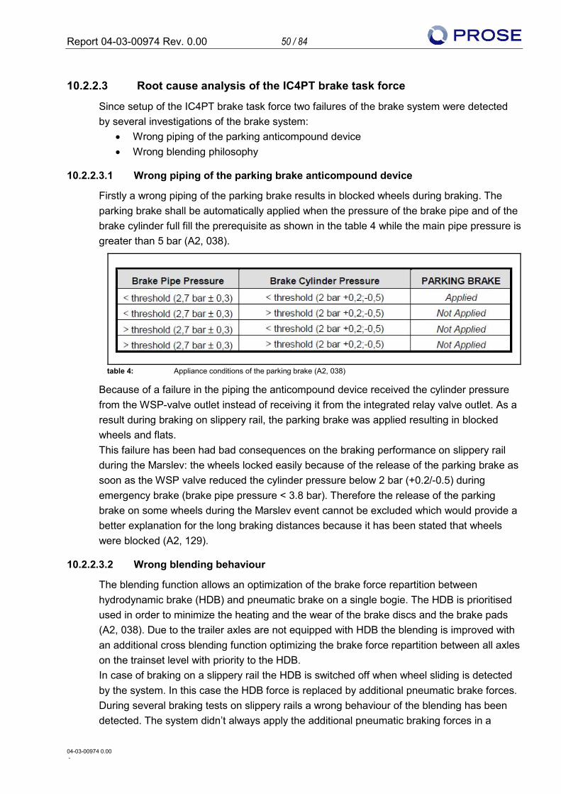
Report 04-03-00974 Rev. 0.00 50 / 84
04-03-00974 0.00 -
10.2.2.3 Root cause analysis of the IC4PT brake task force
Since setup of the IC4PT brake task force two failures of the brake system were detected by several investigations of the brake system:
• Wrong piping of the parking anticompound device • Wrong blending philosophy
10.2.2.3.1 Wrong piping of the parking brake anticompound device
Firstly a wrong piping of the parking brake results in blocked wheels during braking. The parking brake shall be automatically applied when the pressure of the brake pipe and of the brake cylinder full fill the prerequisite as shown in the table 4 while the main pipe pressure is greater than 5 bar (A2, 038).
table 4: Appliance conditions of the parking brake (A2, 038)
Because of a failure in the piping the anticompound device received the cylinder pressure from the WSP-valve outlet instead of receiving it from the integrated relay valve outlet. As a result during braking on slippery rail, the parking brake was applied resulting in blocked wheels and flats. This failure has been had bad consequences on the braking performance on slippery rail during the Marslev: the wheels locked easily because of the release of the parking brake as soon as the WSP valve reduced the cylinder pressure below 2 bar (+0.2/-0.5) during emergency brake (brake pipe pressure < 3.8 bar). Therefore the release of the parking brake on some wheels during the Marslev event cannot be excluded which would provide a better explanation for the long braking distances because it has been stated that wheels were blocked (A2, 129).
10.2.2.3.2 Wrong blending behaviour
The blending function allows an optimization of the brake force repartition between hydrodynamic brake (HDB) and pneumatic brake on a single bogie. The HDB is prioritised used in order to minimize the heating and the wear of the brake discs and the brake pads (A2, 038). Due to the trailer axles are not equipped with HDB the blending is improved with an additional cross blending function optimizing the brake force repartition between all axles on the trainset level with priority to the HDB. In case of braking on a slippery rail the HDB is switched off when wheel sliding is detected by the system. In this case the HDB force is replaced by additional pneumatic brake forces. During several braking tests on slippery rails a wrong behaviour of the blending has been detected. The system didn’t always apply the additional pneumatic braking forces in a
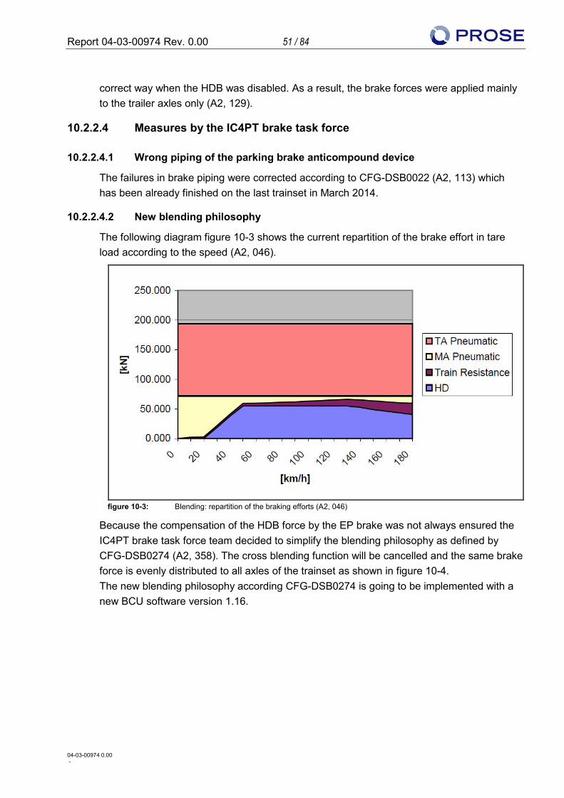
Report 04-03-00974 Rev. 0.00 51 / 84
04-03-00974 0.00 -
correct way when the HDB was disabled. As a result, the brake forces were applied mainly to the trailer axles only (A2, 129).
10.2.2.4 Measures by the IC4PT brake task force
10.2.2.4.1 Wrong piping of the parking brake anticompound device
The failures in brake piping were corrected according to CFG-DSB0022 (A2, 113) which has been already finished on the last trainset in March 2014.
10.2.2.4.2 New blending philosophy
The following diagram figure 10-3 shows the current repartition of the brake effort in tare load according to the speed (A2, 046).
figure 10-3: Blending: repartition of the braking efforts (A2, 046)
Because the compensation of the HDB force by the EP brake was not always ensured the IC4PT brake task force team decided to simplify the blending philosophy as defined by CFG-DSB0274 (A2, 358). The cross blending function will be cancelled and the same brake force is evenly distributed to all axles of the trainset as shown in figure 10-4. The new blending philosophy according CFG-DSB0274 is going to be implemented with a new BCU software version 1.16.
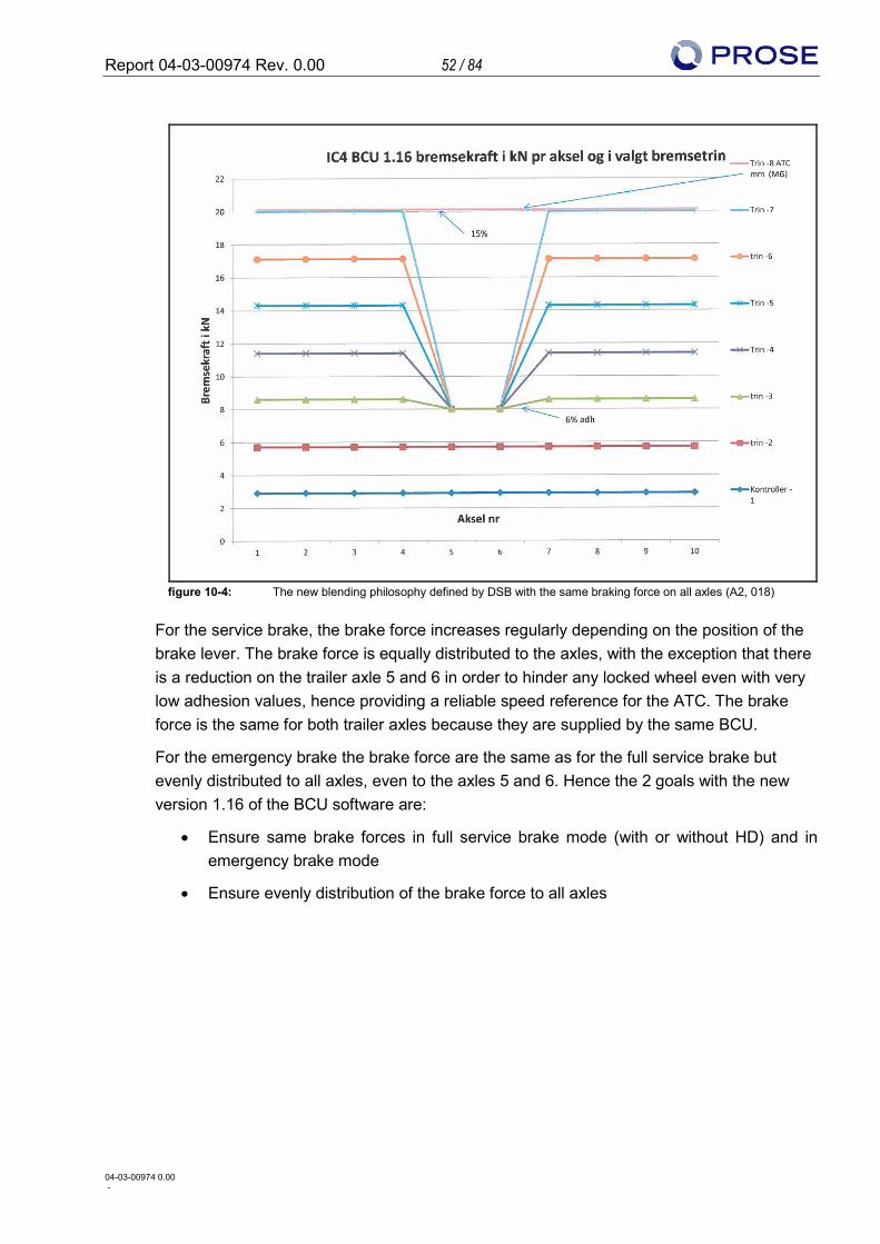
Report 04-03-00974 Rev. 0.00 52 / 84
04-03-00974 0.00 -
figure 10-4: The new blending philosophy defined by DSB with the same braking force on all axles (A2, 018)
For the service brake, the brake force increases regularly depending on the position of the brake lever. The brake force is equally distributed to the axles, with the exception that there is a reduction on the trailer axle 5 and 6 in order to hinder any locked wheel even with very low adhesion values, hence providing a reliable speed reference for the ATC. The brake force is the same for both trailer axles because they are supplied by the same BCU.
For the emergency brake the brake force are the same as for the full service brake but evenly distributed to all axles, even to the axles 5 and 6. Hence the 2 goals with the new version 1.16 of the BCU software are:
• Ensure same brake forces in full service brake mode (with or without HD) and in emergency brake mode
• Ensure evenly distribution of the brake force to all axles
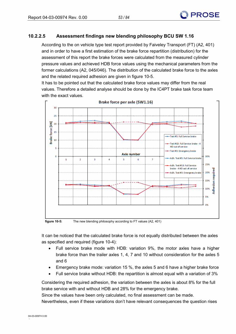
Report 04-03-00974 Rev. 0.00 53 / 84
04-03-00974 0.00 -
10.2.2.5 Assessment findings new blending philosophy BCU SW 1.16
According to the on vehicle type test report provided by Faiveley Transport (FT) (A2, 401) and in order to have a first estimation of the brake force repartition (distribution) for the assessment of this report the brake forces were calculated from the measured cylinder pressure values and achieved HDB force values using the mechanical parameters from the former calculations (A2, 045/046). The distribution of the calculated brake force to the axles and the related required adhesion are given in figure 10-5. It has to be pointed out that the calculated brake force values may differ from the real values. Therefore a detailed analyse should be done by the IC4PT brake task force team with the exact values.
figure 10-5: The new blending philosophy according to FT values (A2, 401)
It can be noticed that the calculated brake force is not equally distributed between the axles as specified and required (figure 10-4):
• Full service brake mode with HDB: variation 9%, the motor axles have a higher brake force than the trailer axles 1, 4, 7 and 10 without consideration for the axles 5 and 6
• Emergency brake mode: variation 15 %, the axles 5 and 6 have a higher brake force • Full service brake without HDB: the repartition is almost equal with a variation of 3%
Considering the required adhesion, the variation between the axles is about 8% for the full brake service with and without HDB and 28% for the emergency brake. Since the values have been only calculated, no final assessment can be made. Nevertheless, even if these variations don’t have relevant consequences the question rises
Report 04-03-00974 Rev. 0.00 54 / 84
04-03-00974 0.00 -
why the brake forces are not evenly distributed to the axle as defined by IC4PT brake task force. The calculated brake forces for the two BCU software versions according to the braking modes shows table 5.
Brake force [kN]
BCU SW1.14 BCU SW1.16
Calculation 01/2005 Test specification
Full service brake with HD 201 196
Full service brake w/o HD 209 194
Emergency brake 225 208
table 5: Brake force according to brake mode (A2, 045/046/401)
The current version 1.14 of the BCU software shows: • The brake force in emergency mode is 7% higher than the brake force of the full
service brake with HDB • The brake force in emergency mode is 12.5% higher than the brake force of the full
service brake without HDB These differences result in a different braking behaviour for the drivers depending on the brake mode used.
The new intended version 1.16 of the BCU software with the calculated brake forces shows: • The brake force in service brake modes with or without the HDB are almost similar • The brake force in the emergency brake mode is 7% higher than for the service
brake without HDB
The comparison of both BCU SW versions shows that the brake force is 8% higher in emergency mode with the current BCU version 1.14. These results in that the braking percentage with the new intended BCU SW version 1.16 are lower. The aim of the version 1.16 is to ensure the same brake force for the different brake modes. It can be concluded that this is not fully achieved. We therefore recommend a careful analyse of the real brake forces for the different braking modes in order to assess if the changes are acceptable or not. Furthermore it has to be carefully analysed if the value of 170% is still achieved with regard to the braking distances which will be measured during the dynamic tests.
Report 04-03-00974 Rev. 0.00 55 / 84
04-03-00974 0.00 -
10.2.2.6 Assessment results and recommendations
10.2.2.6.1 Results
The task force implemented after the Marslev incident revealed two major failures in the system design that couldn’t be easily detected during the dynamic type tests but should have been detected during the static type tests. The measures defined and implemented by the IC4PT brake task force seem adapted in order to get rid of the speed limitation. By today it is not possible to have a final assessment of these measures because the results of the tests performed for the validation of the WSP-system and the results of the dynamic tests with the new BCU software version 1.16 (CFG-DSB0274) are not known. Furthermore a comprehensive validation plan of the CFG-DSB0274 is missing for:
• Criterions for the validation of the on vehicle tests (A2, 401) • New brake percentage and distances to be calculated • Validation of the measured braking distance according to a new brake distance
calculation (it is surprising that FT defines unilaterally the test specification and that the IC4PT brake task force doesn’t have the lead for the definition of the tests requirements and all necessary validation criterions)
• No validation in regard to side effects of the new brake force distribution and changed braking torques are addressed:
o Possible impact on the performance of the WSP-system o Thermal behaviour of the brake components o Resulting stresses to adjacent components (e.g. bogie components like
axles, bogie frame structures)
10.2.2.6.2 Recommendation
The dynamic tests of the software version of the BCU 1.16 were performed by FT in October 2014. Unfortunately neither the test specification nor the test results according to the dynamic test program (A2, 382) could be provided during the assessment (A2, 390) due to incomplete document status by FT. Further documents beside the FT dynamic tests especially in regard to the complete validation of the new BCU software version 1.16 and their side effects to adjacent components or subsystems could not be provided by IC4PT which limited this assessment task.
Report 04-03-00974 Rev. 0.00 56 / 84
04-03-00974 0.00 -
Since a complete analysis and validation of this complex CFG-DSB0274 is necessary before the implementation on the IC4 following measures and validation points are recommended strongly:
• As mentioned before, the brake percentage has to be calculated according to the measured brake distance in order to define the value that can be set in the ATC and the related maximal operating speed
• The report made by FT (A2, 401) and the dynamic tests performed need to be analysed:
o As mentioned before the brake force is not equally distributed to all axles and the total brake force is 7% higher with the emergency brake mode. The criterions for the acceptable braking force per axle have to be defined in consideration with the possible influences to the components of the system.
o The HDB force achieved is around 20% lower than the requested value, resulting in higher braking forces to be performed by the pneumatic brake. This difference is not fully explained by FT because this is not part of its scope and since the cylinder pressures are according to the nominal values the results could be satisfactory in the view of FT. Nevertheless in order to assess if these results are satisfactory for the reliable behaviour of the whole system a closer analyse of this point is strongly recommended
o For the emergency brake mode the axle 5 was isolated during the test, this is not according to the test specification (A2, 305)
• No brake calculation has been provided by the suppliers of the brake system. The requirements for the assessment of the measured braking distance are normally defined from the calculation. The basis for the acceptance of the dynamic brake tests is therefore not clear.
• The side effects of the new brake force distribution have to be analysed and verified carefully by using measured values from the dynamic tests:
o Influence and impacts to the performance of the WSP-system in order to ensure that the results of the tests performed for the validation of the WSP-system (See chapter 10.2.2.6.1) remain valid after the implementation of this new blending software release
o The thermal behaviour of the wear components especially brake discs o The stresses resulting to the bogie components, especially the axles and
bogie frame which have to be validated according to the measured braking torques
10.2.2.7 System reliability
Beside the above mentioned issues no critical failure of the brake system occurred. Nevertheless some components (e.g. PSL, PFA and calliper switches) have a huge negative impact on the reliability and availability of the trainsets. The following CFG’s were opened:
Report 04-03-00974 Rev. 0.00 57 / 84
04-03-00974 0.00 -
10.2.2.7.1 CFG-DSB0162: PSL switch on the brake pipe
The pressure of the brake pipe is monitored by a dedicated pressure transducer and by a set of pressure switches. These pressure switches are used during the safety brake application control. One of these switches is dedicated for the detection of low pressure (PSL): this function allow to energise the EVSOCC valves when the pressure in the brake pipe is lower to 2.5 bar and remove this signal when the pressure in the brake pipe rise to 3.5 bar. There is one PSL switch per BCU providing a high redundancy level. The CFG-DSB0162 was opened to improve the reliability of the switch (exchange of the switch).
10.2.2.7.2 CFG-DSB0276: PFA switch for the cylinder pressure
The cylinder pressure of each axle is monitored by the PFA switch placed after the WSP valve. The PFA value is ON if the cylinder pressure is higher than 0.5 bar (meaning the brake is not released). The value of the PFA is compared with the value provided by the BCU itself. If at least one PFA switch of a not isolated axle is ON the driver is informed about friction brake application in progress. In operation when the brake demand is released, there is an error if the holding brake is not released within 8 seconds during the start up. Nevertheless this control delay seems too short and will be increased to 15 seconds. It has to be mentioned that the cylinder pressure is additionally checked by the pressure transducers TBC between the brake panel and the bogie hose. Each cylinder pressure is therefore monitored by three different components.
10.2.2.7.3 Calliper switch
One calliper switch is mounted on each calliper with parking brake in order to detect the status of the brake (Released or Applied) when the caliper brake is isolated. Additionally each switch gives a further sure braking indication: it is activated when the calliper is moved from the idle position and start braking due to pressure inside the brake cylinders, despite of the brake mode: service (EP or IP) or parking. Many failures occurred because the switch is not reliable: in operation the brake are wrongly detected applied and the trainset is stopped. With the version 2.1 of the TCMS, in case a closed caliper is detected the state of PFA switch and BCU will be additionally checked providing a reliable detection. Nevertheless this change may annihilate the need for the calliper switch since the first reason for the implementation of these switch is to give a sure not braking indication, even if the parking brake is isolated (A2, 038/047). Before proceeding to this modification, it has to be ensured that the side effects have been analyzed considering the whole safety level of the brake system.
Report 04-03-00974 Rev. 0.00 58 / 84
04-03-00974 0.00 -
10.2.2.7.4 Results
The reliability problems that occur because of the different switches (PSL, PFA and calliper switch) show that the brake system of the IC4/2 is complex with numerous monitoring equipment and redundancies. In deep tuning and verification will remain needed during the next months and we advise to strengthen the task force with the aim:
• To deepen the knowledge of the system and the components
• To analyse the side effects of each modification
• To identify the possibilities to increase the reliability of the system
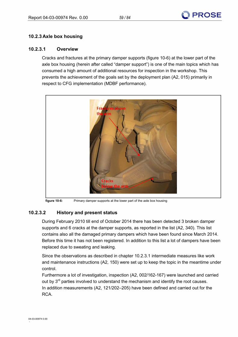
Report 04-03-00974 Rev. 0.00 59 / 84
04-03-00974 0.00 -
10.2.3 Axle box housing
10.2.3.1 Overview
Cracks and fractures at the primary damper supports (figure 10-6) at the lower part of the axle box housing (herein after called “damper support”) is one of the main topics which has consumed a high amount of additional resources for inspection in the workshop. This prevents the achievement of the goals set by the deployment plan (A2, 015) primarily in respect to CFG implementation (MDBF performance).
figure 10-6: Primary damper supports at the lower part of the axle box housing
10.2.3.2 History and present status
During February 2010 till end of October 2014 there has been detected 3 broken damper supports and 6 cracks at the damper supports, as reported in the list (A2, 340). This list contains also all the damaged primary dampers which have been found since March 2014. Before this time it has not been registered. In addition to this list a lot of dampers have been replaced due to sweating and leaking.
Since the observations as described in chapter 10.2.3.1 intermediate measures like work and maintenance instructions (A2, 150) were set up to keep the topic in the meantime under control. Furthermore a lot of investigation, inspection (A2, 002/162-167) were launched and carried out by 3rd parties involved to understand the mechanism and identify the root causes. In addition measurements (A2, 121/202–205) have been defined and carried out for the RCA.
Report 04-03-00974 Rev. 0.00 60 / 84
04-03-00974 0.00 -
Since early October, week 40/2014 (A1, 23) the interval for inspection of wheel condition, damper support and primary damper has been enlarged from 7 days or 5,000 km to 30,000 km (A2, 119) approved by DSB-S (A1, 23).
10.2.3.3 Root cause analysis
The RCA done by IC4PT shows following results:
1. Worst wheel conditions
a) Bad wheel maintenance based on faulty maintenance instructions, checking and measurement wheels at 180,000 km intervals (A2, 002/130/206)
b) Over breaking trailer especially leading axles due to BCU SW failures regarding wrong cross-blending in case of loss the retarder of the PP (A1, 23), details see chapter 10.2.2.3.2
c) Failures in brake piping acc. CFG-DSB0022 (A2, 113) (see chapter 10.2.2.3.1)
2. High reaction forces of the primary damper
a) Outside of the normal operating range of the primary damper the characteristic is exceptional strong progressive (A2, 171)
Exceptional cases beyond normal operating modes for instance coming from collision of the wheels with objects or driving by worst wheel conditions will lead to high compression speeds for the damper.
Two different kind of weak points at the damper support were identified:
A) 3 fractured damper supports in the area over the arm close to the casting edge (have been only on the leading trailer axles) see figure 10-7. 1 crack at the damper support in the area over the arm (on a driven axle)
B) 5 cracks at the damper supports in the area of the bottom part, at the reinforcement under the arm have, which is the most vulnerable place for fatigue cracks concerning the maximum permissible stress level as predicted by the FEM calculation (A2, 117) see figure 10-8.
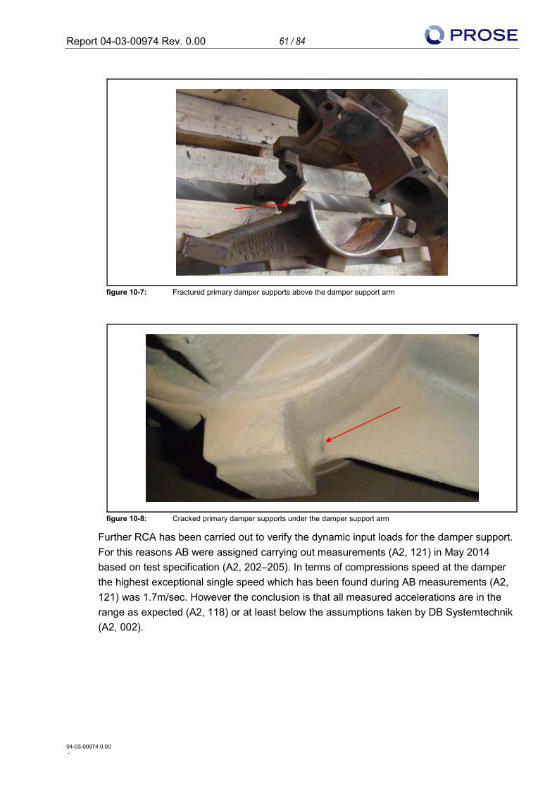
Report 04-03-00974 Rev. 0.00 61 / 84
04-03-00974 0.00 -
figure 10-7: Fractured primary damper supports above the damper support arm
figure 10-8: Cracked primary damper supports under the damper support arm
Further RCA has been carried out to verify the dynamic input loads for the damper support. For this reasons AB were assigned carrying out measurements (A2, 121) in May 2014 based on test specification (A2, 202–205). In terms of compressions speed at the damper the highest exceptional single speed which has been found during AB measurements (A2, 121) was 1.7m/sec. However the conclusion is that all measured accelerations are in the range as expected (A2, 118) or at least below the assumptions taken by DB Systemtechnik (A2, 002).
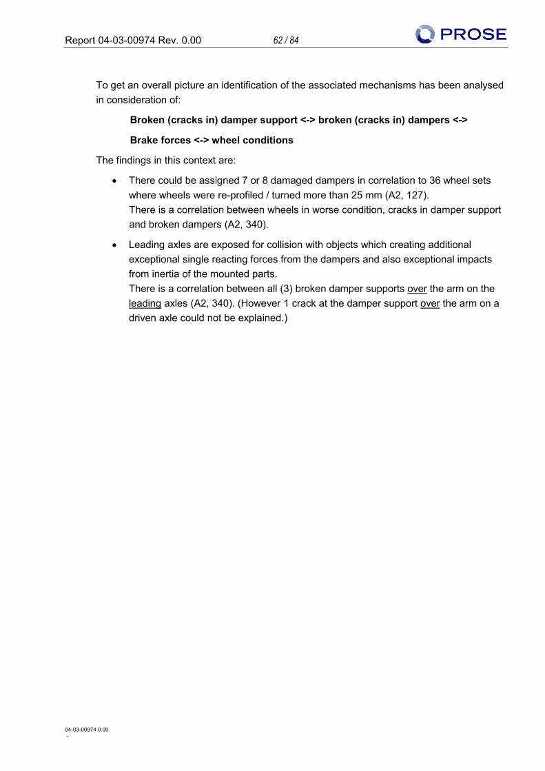
Report 04-03-00974 Rev. 0.00 62 / 84
04-03-00974 0.00 -
To get an overall picture an identification of the associated mechanisms has been analysed in consideration of:
Broken (cracks in) damper support <-> broken (cracks in) dampers <->
Brake forces <-> wheel conditions
The findings in this context are:
• There could be assigned 7 or 8 damaged dampers in correlation to 36 wheel sets where wheels were re-profiled / turned more than 25 mm (A2, 127). There is a correlation between wheels in worse condition, cracks in damper support and broken dampers (A2, 340).
• Leading axles are exposed for collision with objects which creating additional exceptional single reacting forces from the dampers and also exceptional impacts from inertia of the mounted parts. There is a correlation between all (3) broken damper supports over the arm on the leading axles (A2, 340). (However 1 crack at the damper support over the arm on a driven axle could not be explained.)
Report 04-03-00974 Rev. 0.00 63 / 84
04-03-00974 0.00 -
10.2.3.4 Measures defined by DSB
The proposed measures by IC4PT to solve this issue are following:
1. Normal wheel conditions
a) Improvement of the wheel maintenance according to a wheel manual which will shortly installed (common for all trainsets at the DSB fleet) and an specific maintenance procedure already documented in SAP which request a visual inspection latest within 30,000 km (A2, 370)
Besides this there has been also decided to carry out “comfort turnings” of the wheels at 80,000 km at front bogies and 120,000 km at intermediate bogies against (A2, 130)
b) Monitoring wheel condition at track side installed WILD system (A2, 128) between Copenhagen and Aarhus at the belt bridge (more will be installed in the future)
c) A new BCU SW (Version 1.16) according CFG-DSB0274 will be provided which proposed corrections in blending amongst other things (details refer to chapter 10.2.2.4).
d) Correction of failures in brake piping according CFG-DSB0022 (A2, 113) which has been already finished on the last trainset in March 2014.
e) An additional development proposal is the evaluation of changing the hardness of the wheel. The intention is to change the currently wheel material R7 to “Superlos” (provided by supplier Lucchini in Italy), which reflects the upper part of the yield strength of R8 material.
2. New primary damper
A new primary damper by Seneberg (A2, 176/177) is defined in CFG-DSB0281 (A2, 174) to provide one third of the reaction force at very high compression (A2, 171) against the existing one (A2, 169). This has a high priority but does not belong to the top ten of CFG.
Changes at the damper support of the axle box itself are not considered since above mentioned measures should eliminate the negative effects stressing the damper support.
Report 04-03-00974 Rev. 0.00 64 / 84
04-03-00974 0.00 -
10.2.3.5 Assessment Findings
10.2.3.5.1 Root cause analysis
The dynamic input loads to the damper support have been verified as explained above in chapter 10.2.3.3 based on measured accelerations but didn’t consider the measured strains at the different strain gauge (DMS) locations. Furthermore it has to be stated that there is concern in regard to the verification of the axle box design itself as per particulars given below: 1. The AB dynamic measurements on line tests in May 2014 did not evaluate the DMS at
the seam, where the damage occurred for whatever reason. The maximum measured dynamic stresses at test on line under operational conditions shows approximately 34 MPa for a bad wheel and only 9 MPa for a wheel in good condition (A2, 121). The measured degraded wheel with out of roundness was 0.4 mm against 3.27 mm (worst wheel condition) which has been founded in former times during operation. Anyway these values for out-of-roundness of 0.4 mm are under the permissible strength value given by the last re-calculation of the sub-supplier FAG (A2, 117) who has the design responsibility.
2. The fatigue strength value used by FAG (A2, 117) is higher than the value according to the FKM- guideline (i.e. compression-tension endurance limit). Although a casting surface factor has been taken into account no safety factor value in terms of casting material and material safety factor generally has been considered. Unfortunately no raw-cast part drawings or information about inspection and cast factors are available.
That would mean that new evidence by FEM should be provided resulting in smaller security due to the reduced permissible strength value. In sum, the reflected safety does not correspond to FAG reports (A2, 117/163/164/165).
3. Furthermore the used “analytical surface” in FEM model (A2, 117) is too stiff for realistic
FEM calculation. For instance, local deformation by inclination of the bearing housing is not covered which leads to more (unknown) pre-load of the screws causing in additional superimposed tensile stress. This could be critical for the fatigue strength and has not been considered in the calculation, too. In addition the stiffness of the bearing itself should be considered as well which also leads to more realistic results and is state of the art today.
Last but not least for a complete RCA geometrical interferences must be excluded as well. From design point of view unfortunately there is no possibility to identify the proper fit between the outer bearing ring and the lower axle box housing inner shell due to missing detailed information by the sub-supplier, as already stated by former investigation (A2, 002).
These described effects (local deformation by inclination of the bearing housing; consideration of bearing stiffness; geometrical interference) could lead to higher pre-
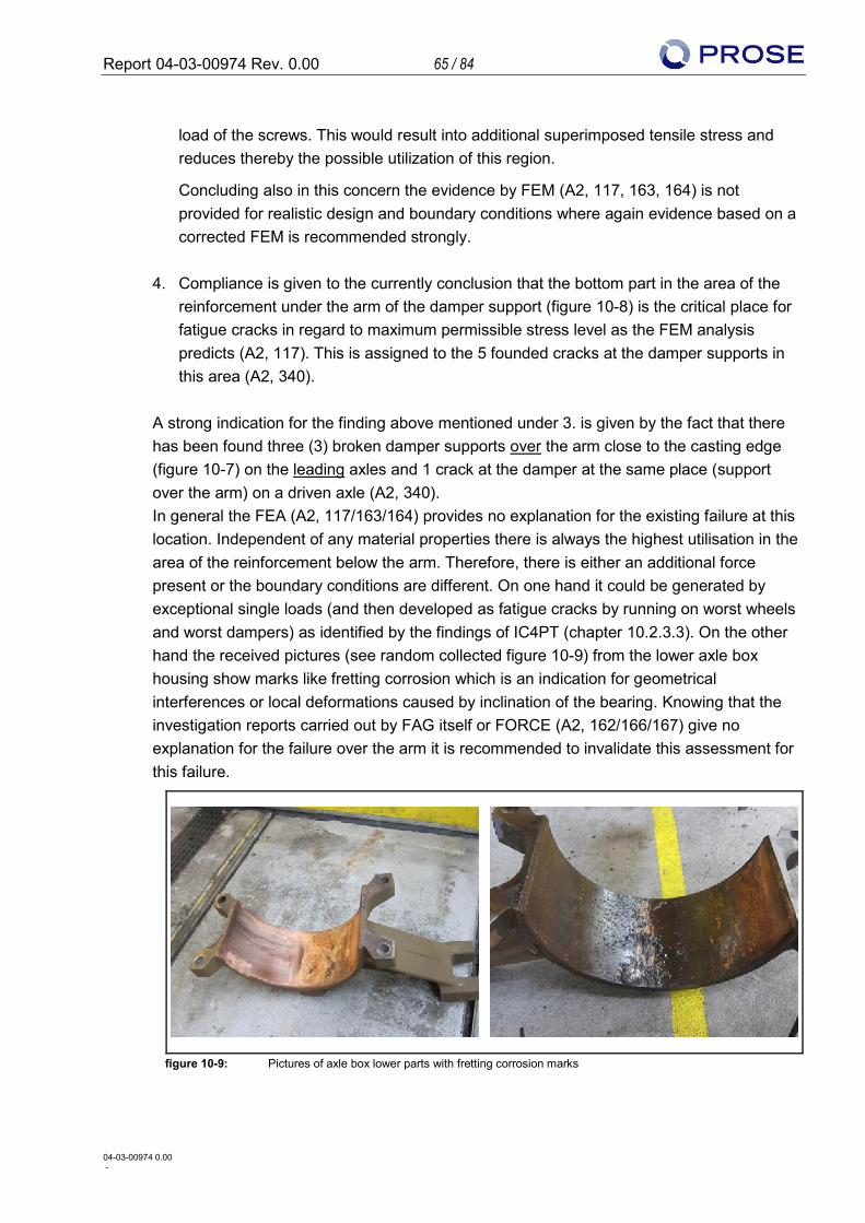
Report 04-03-00974 Rev. 0.00 65 / 84
04-03-00974 0.00 -
load of the screws. This would result into additional superimposed tensile stress and reduces thereby the possible utilization of this region.
Concluding also in this concern the evidence by FEM (A2, 117, 163, 164) is not provided for realistic design and boundary conditions where again evidence based on a corrected FEM is recommended strongly.
4. Compliance is given to the currently conclusion that the bottom part in the area of the reinforcement under the arm of the damper support (figure 10-8) is the critical place for fatigue cracks in regard to maximum permissible stress level as the FEM analysis predicts (A2, 117). This is assigned to the 5 founded cracks at the damper supports in this area (A2, 340).
A strong indication for the finding above mentioned under 3. is given by the fact that there has been found three (3) broken damper supports over the arm close to the casting edge (figure 10-7) on the leading axles and 1 crack at the damper at the same place (support over the arm) on a driven axle (A2, 340). In general the FEA (A2, 117/163/164) provides no explanation for the existing failure at this location. Independent of any material properties there is always the highest utilisation in the area of the reinforcement below the arm. Therefore, there is either an additional force present or the boundary conditions are different. On one hand it could be generated by exceptional single loads (and then developed as fatigue cracks by running on worst wheels and worst dampers) as identified by the findings of IC4PT (chapter 10.2.3.3). On the other hand the received pictures (see random collected figure 10-9) from the lower axle box housing show marks like fretting corrosion which is an indication for geometrical interferences or local deformations caused by inclination of the bearing. Knowing that the investigation reports carried out by FAG itself or FORCE (A2, 162/166/167) give no explanation for the failure over the arm it is recommended to invalidate this assessment for this failure.
figure 10-9: Pictures of axle box lower parts with fretting corrosion marks
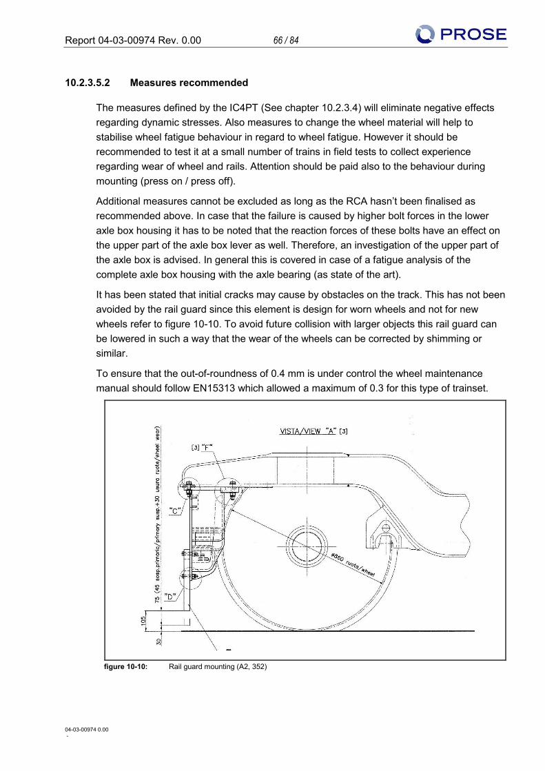
Report 04-03-00974 Rev. 0.00 66 / 84
04-03-00974 0.00 -
10.2.3.5.2 Measures recommended
The measures defined by the IC4PT (See chapter 10.2.3.4) will eliminate negative effects regarding dynamic stresses. Also measures to change the wheel material will help to stabilise wheel fatigue behaviour in regard to wheel fatigue. However it should be recommended to test it at a small number of trains in field tests to collect experience regarding wear of wheel and rails. Attention should be paid also to the behaviour during mounting (press on / press off).
Additional measures cannot be excluded as long as the RCA hasn’t been finalised as recommended above. In case that the failure is caused by higher bolt forces in the lower axle box housing it has to be noted that the reaction forces of these bolts have an effect on the upper part of the axle box lever as well. Therefore, an investigation of the upper part of the axle box is advised. In general this is covered in case of a fatigue analysis of the complete axle box housing with the axle bearing (as state of the art).
It has been stated that initial cracks may cause by obstacles on the track. This has not been avoided by the rail guard since this element is design for worn wheels and not for new wheels refer to figure 10-10. To avoid future collision with larger objects this rail guard can be lowered in such a way that the wear of the wheels can be corrected by shimming or similar.
To ensure that the out-of-roundness of 0.4 mm is under control the wheel maintenance manual should follow EN15313 which allowed a maximum of 0.3 for this type of trainset.
figure 10-10: Rail guard mounting (A2, 352)
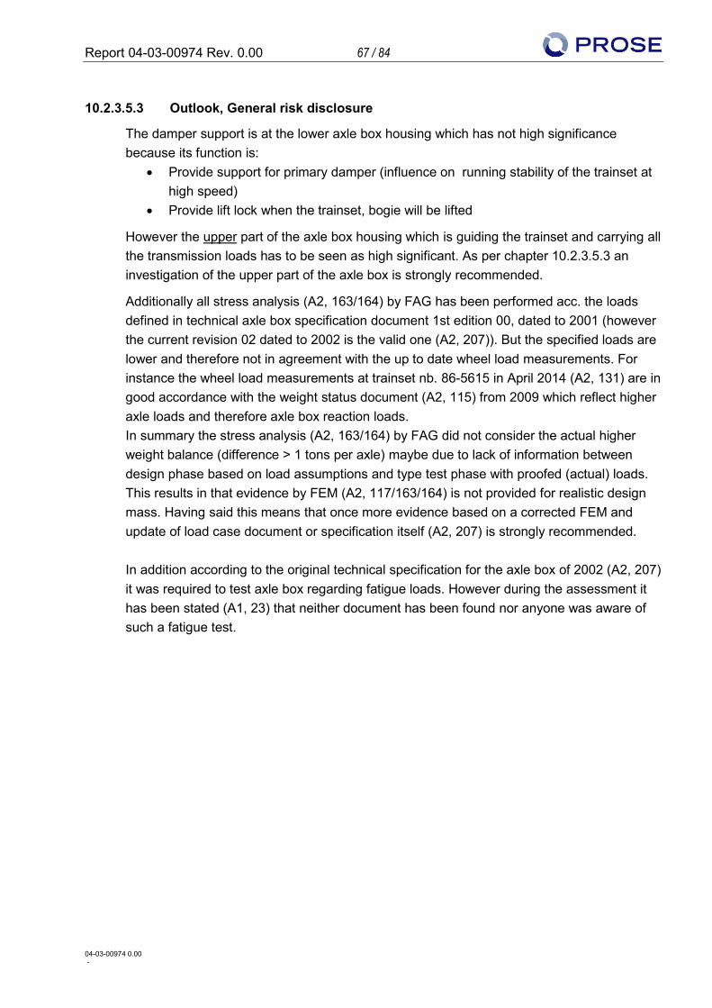
Report 04-03-00974 Rev. 0.00 67 / 84
04-03-00974 0.00 -
10.2.3.5.3 Outlook, General risk disclosure
The damper support is at the lower axle box housing which has not high significance because its function is:
• Provide support for primary damper (influence on running stability of the trainset at high speed)
• Provide lift lock when the trainset, bogie will be lifted
However the upper part of the axle box housing which is guiding the trainset and carrying all the transmission loads has to be seen as high significant. As per chapter 10.2.3.5.3 an investigation of the upper part of the axle box is strongly recommended.
Additionally all stress analysis (A2, 163/164) by FAG has been performed acc. the loads defined in technical axle box specification document 1st edition 00, dated to 2001 (however the current revision 02 dated to 2002 is the valid one (A2, 207)). But the specified loads are lower and therefore not in agreement with the up to date wheel load measurements. For instance the wheel load measurements at trainset nb. 86-5615 in April 2014 (A2, 131) are in good accordance with the weight status document (A2, 115) from 2009 which reflect higher axle loads and therefore axle box reaction loads. In summary the stress analysis (A2, 163/164) by FAG did not consider the actual higher weight balance (difference > 1 tons per axle) maybe due to lack of information between design phase based on load assumptions and type test phase with proofed (actual) loads. This results in that evidence by FEM (A2, 117/163/164) is not provided for realistic design mass. Having said this means that once more evidence based on a corrected FEM and update of load case document or specification itself (A2, 207) is strongly recommended. In addition according to the original technical specification for the axle box of 2002 (A2, 207) it was required to test axle box regarding fatigue loads. However during the assessment it has been stated (A1, 23) that neither document has been found nor anyone was aware of such a fatigue test.
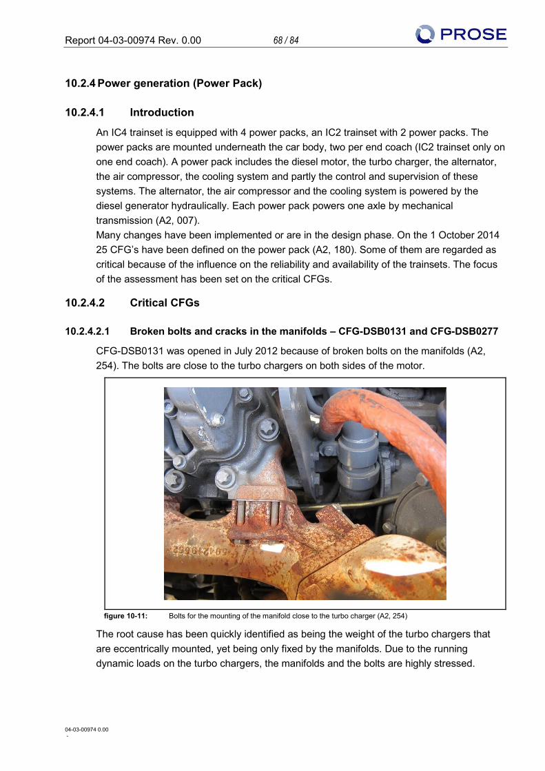
Report 04-03-00974 Rev. 0.00 68 / 84
04-03-00974 0.00 -
10.2.4 Power generation (Power Pack)
10.2.4.1 Introduction
An IC4 trainset is equipped with 4 power packs, an IC2 trainset with 2 power packs. The power packs are mounted underneath the car body, two per end coach (IC2 trainset only on one end coach). A power pack includes the diesel motor, the turbo charger, the alternator, the air compressor, the cooling system and partly the control and supervision of these systems. The alternator, the air compressor and the cooling system is powered by the diesel generator hydraulically. Each power pack powers one axle by mechanical transmission (A2, 007). Many changes have been implemented or are in the design phase. On the 1 October 2014 25 CFG’s have been defined on the power pack (A2, 180). Some of them are regarded as critical because of the influence on the reliability and availability of the trainsets. The focus of the assessment has been set on the critical CFGs.
10.2.4.2 Critical CFGs
10.2.4.2.1 Broken bolts and cracks in the manifolds – CFG-DSB0131 and CFG-DSB0277
CFG-DSB0131 was opened in July 2012 because of broken bolts on the manifolds (A2, 254). The bolts are close to the turbo chargers on both sides of the motor.
figure 10-11: Bolts for the mounting of the manifold close to the turbo charger (A2, 254)
The root cause has been quickly identified as being the weight of the turbo chargers that are eccentrically mounted, yet being only fixed by the manifolds. Due to the running dynamic loads on the turbo chargers, the manifolds and the bolts are highly stressed.
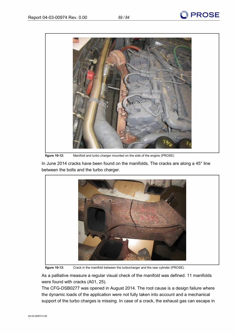
Report 04-03-00974 Rev. 0.00 69 / 84
04-03-00974 0.00 -
figure 10-12: Manifold and turbo charger mounted on the side of the engine (PROSE)
In June 2014 cracks have been found on the manifolds. The cracks are along a 45° line between the bolts and the turbo charger.
figure 10-13: Crack in the manifold between the turbocharger and the rear cylinder (PROSE)
As a palliative measure a regular visual check of the manifold was defined. 11 manifolds were found with cracks (A01, 25). The CFG-DSB0277 was opened in August 2014. The root cause is a design failure where the dynamic loads of the application were not fully taken into account and a mechanical support of the turbo charges is missing. In case of a crack, the exhaust gas can escape in
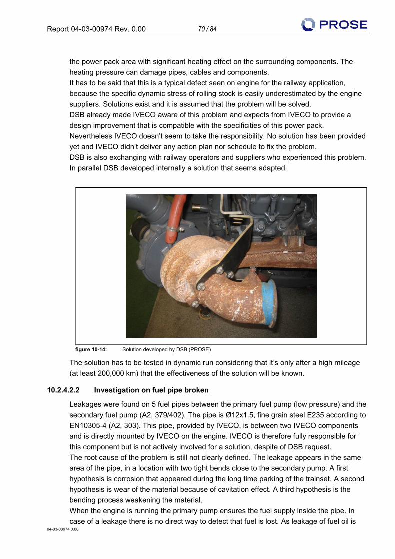
Report 04-03-00974 Rev. 0.00 70 / 84
04-03-00974 0.00 -
the power pack area with significant heating effect on the surrounding components. The heating pressure can damage pipes, cables and components. It has to be said that this is a typical defect seen on engine for the railway application, because the specific dynamic stress of rolling stock is easily underestimated by the engine suppliers. Solutions exist and it is assumed that the problem will be solved. DSB already made IVECO aware of this problem and expects from IVECO to provide a design improvement that is compatible with the specificities of this power pack. Nevertheless IVECO doesn’t seem to take the responsibility. No solution has been provided yet and IVECO didn’t deliver any action plan nor schedule to fix the problem. DSB is also exchanging with railway operators and suppliers who experienced this problem. In parallel DSB developed internally a solution that seems adapted.
figure 10-14: Solution developed by DSB (PROSE)
The solution has to be tested in dynamic run considering that it’s only after a high mileage (at least 200,000 km) that the effectiveness of the solution will be known.
10.2.4.2.2 Investigation on fuel pipe broken
Leakages were found on 5 fuel pipes between the primary fuel pump (low pressure) and the secondary fuel pump (A2, 379/402). The pipe is Ø12x1.5, fine grain steel E235 according to EN10305-4 (A2, 303). This pipe, provided by IVECO, is between two IVECO components and is directly mounted by IVECO on the engine. IVECO is therefore fully responsible for this component but is not actively involved for a solution, despite of DSB request. The root cause of the problem is still not clearly defined. The leakage appears in the same area of the pipe, in a location with two tight bends close to the secondary pump. A first hypothesis is corrosion that appeared during the long time parking of the trainset. A second hypothesis is wear of the material because of cavitation effect. A third hypothesis is the bending process weakening the material. When the engine is running the primary pump ensures the fuel supply inside the pipe. In case of a leakage there is no direct way to detect that fuel is lost. As leakage of fuel oil is
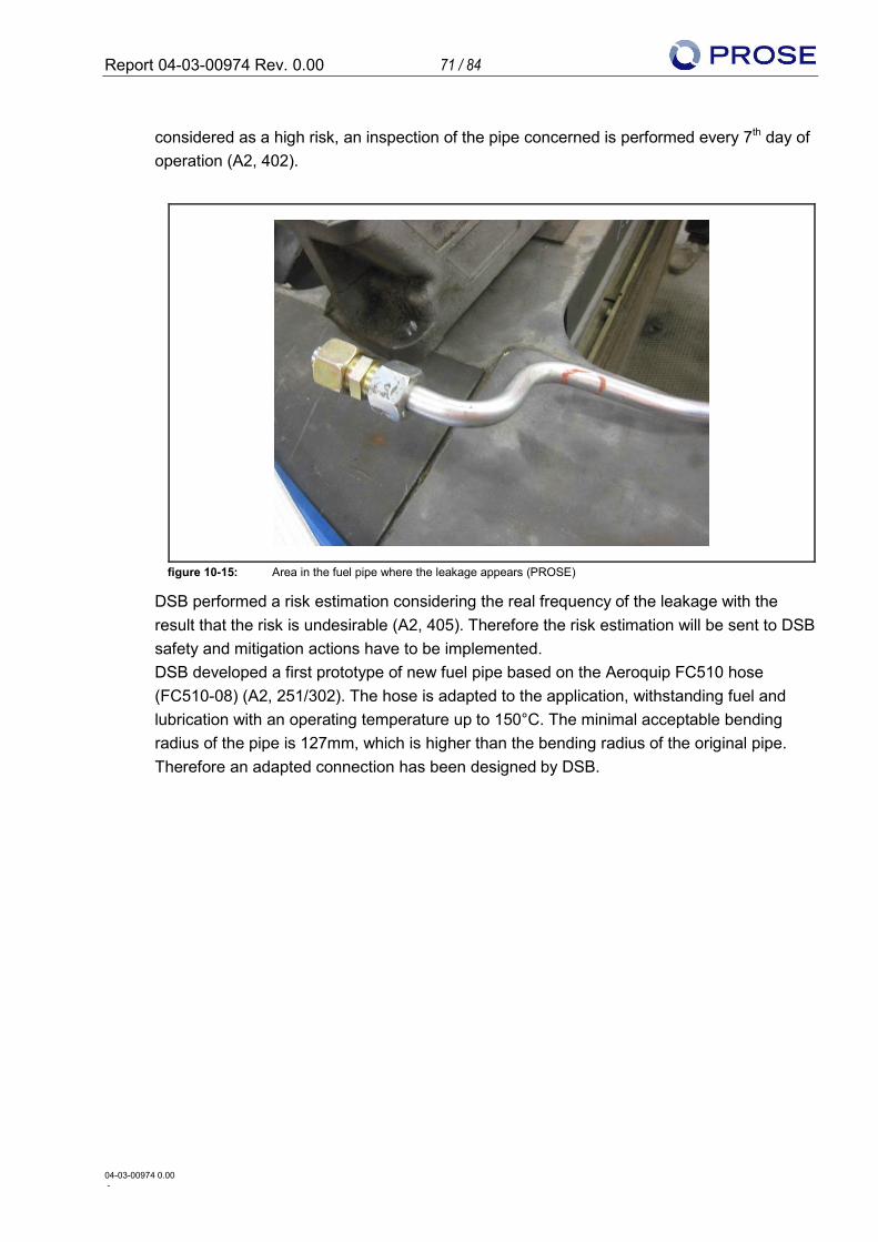
Report 04-03-00974 Rev. 0.00 71 / 84
04-03-00974 0.00 -
considered as a high risk, an inspection of the pipe concerned is performed every 7th day of operation (A2, 402).
figure 10-15: Area in the fuel pipe where the leakage appears (PROSE)
DSB performed a risk estimation considering the real frequency of the leakage with the result that the risk is undesirable (A2, 405). Therefore the risk estimation will be sent to DSB safety and mitigation actions have to be implemented. DSB developed a first prototype of new fuel pipe based on the Aeroquip FC510 hose (FC510-08) (A2, 251/302). The hose is adapted to the application, withstanding fuel and lubrication with an operating temperature up to 150°C. The minimal acceptable bending radius of the pipe is 127mm, which is higher than the bending radius of the original pipe. Therefore an adapted connection has been designed by DSB.
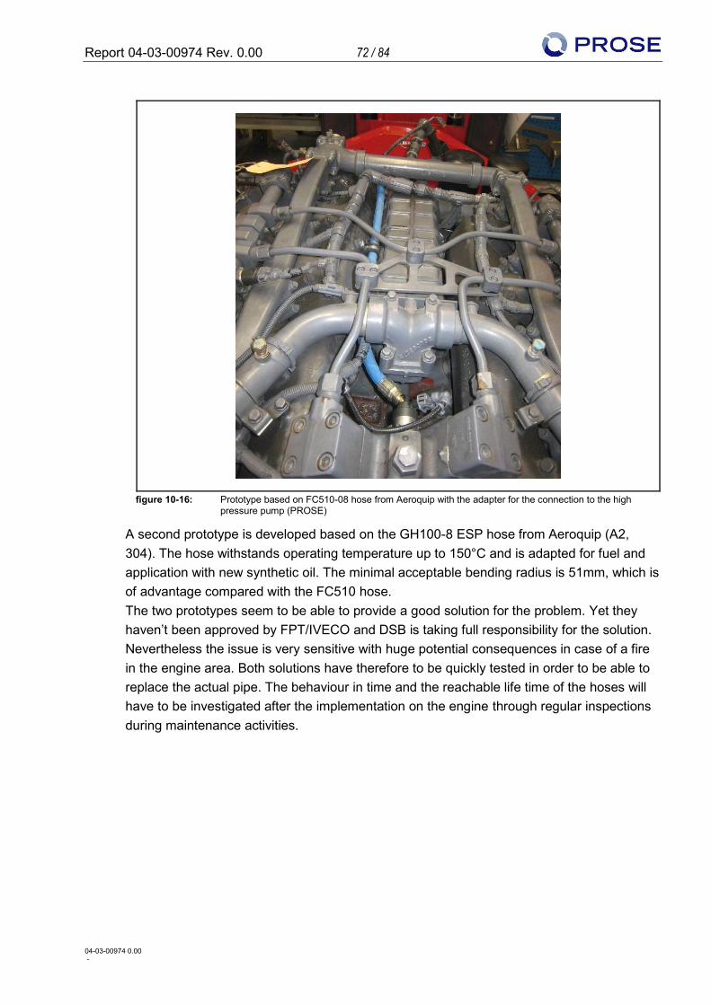
Report 04-03-00974 Rev. 0.00 72 / 84
04-03-00974 0.00 -
figure 10-16: Prototype based on FC510-08 hose from Aeroquip with the adapter for the connection to the high pressure pump (PROSE)
A second prototype is developed based on the GH100-8 ESP hose from Aeroquip (A2, 304). The hose withstands operating temperature up to 150°C and is adapted for fuel and application with new synthetic oil. The minimal acceptable bending radius is 51mm, which is of advantage compared with the FC510 hose. The two prototypes seem to be able to provide a good solution for the problem. Yet they haven’t been approved by FPT/IVECO and DSB is taking full responsibility for the solution. Nevertheless the issue is very sensitive with huge potential consequences in case of a fire in the engine area. Both solutions have therefore to be quickly tested in order to be able to replace the actual pipe. The behaviour in time and the reachable life time of the hoses will have to be investigated after the implementation on the engine through regular inspections during maintenance activities.
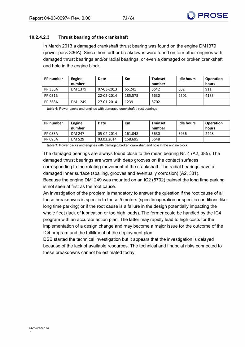
Report 04-03-00974 Rev. 0.00 73 / 84
04-03-00974 0.00 -
10.2.4.2.3 Thrust bearing of the crankshaft
In March 2013 a damaged crankshaft thrust bearing was found on the engine DM1379 (power pack 336A). Since then further breakdowns were found on four other engines with damaged thrust bearings and/or radial bearings, or even a damaged or broken crankshaft and hole in the engine block.
PP number Engine
number Date Km Trainset
number Idle hours Operation
hours PP 336A DM 1379 07-03-2013 65.241 5642 652 911 PP 031B 22-05-2014 185.575 5630 2501 4183 PP 368A DM 1249 27-01-2014 1239 5702
table 6: Power packs and engines with damaged crankshaft thrust bearings
PP number Engine
number Date Km Trainset
number Idle hours Operation
hours PP 053A DM 247 05-02-2014 161.048 5630 3956 2428 PP 095A DM 529 03.03.2014 158.695 5648
table 7: Power packs and engines with damaged/broken crankshaft and hole in the engine block
The damaged bearings are always found close to the mean bearing Nr. 4 (A2, 385). The damaged thrust bearings are worn with deep grooves on the contact surfaces corresponding to the rotating movement of the crankshaft. The radial bearings have a damaged inner surface (spalling, grooves and eventually corrosion) (A2, 381). Because the engine DM1249 was mounted on an IC2 (5702) trainset the long time parking is not seen at first as the root cause. An investigation of the problem is mandatory to answer the question if the root cause of all these breakdowns is specific to these 5 motors (specific operation or specific conditions like long time parking) or if the root cause is a failure in the design potentially impacting the whole fleet (lack of lubrication or too high loads). The former could be handled by the IC4 program with an accurate action plan. The latter may rapidly lead to high costs for the implementation of a design change and may become a major issue for the outcome of the IC4 program and the fulfillment of the deployment plan. DSB started the technical investigation but it appears that the investigation is delayed because of the lack of available resources. The technical and financial risks connected to these breakdowns cannot be estimated today.
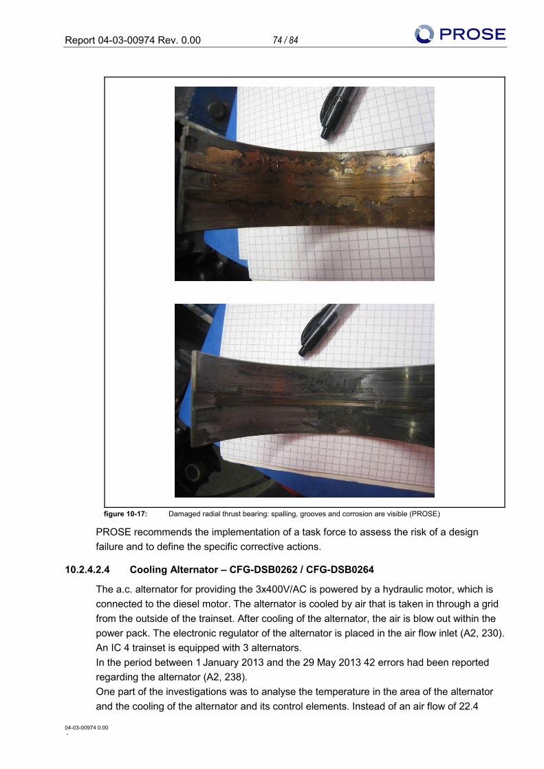
Report 04-03-00974 Rev. 0.00 74 / 84
04-03-00974 0.00 -
figure 10-17: Damaged radial thrust bearing: spalling, grooves and corrosion are visible (PROSE)
PROSE recommends the implementation of a task force to assess the risk of a design failure and to define the specific corrective actions.
10.2.4.2.4 Cooling Alternator – CFG-DSB0262 / CFG-DSB0264
The a.c. alternator for providing the 3x400V/AC is powered by a hydraulic motor, which is connected to the diesel motor. The alternator is cooled by air that is taken in through a grid from the outside of the trainset. After cooling of the alternator, the air is blow out within the power pack. The electronic regulator of the alternator is placed in the air flow inlet (A2, 230). An IC 4 trainset is equipped with 3 alternators. In the period between 1 January 2013 and the 29 May 2013 42 errors had been reported regarding the alternator (A2, 238). One part of the investigations was to analyse the temperature in the area of the alternator and the cooling of the alternator and its control elements. Instead of an air flow of 22.4
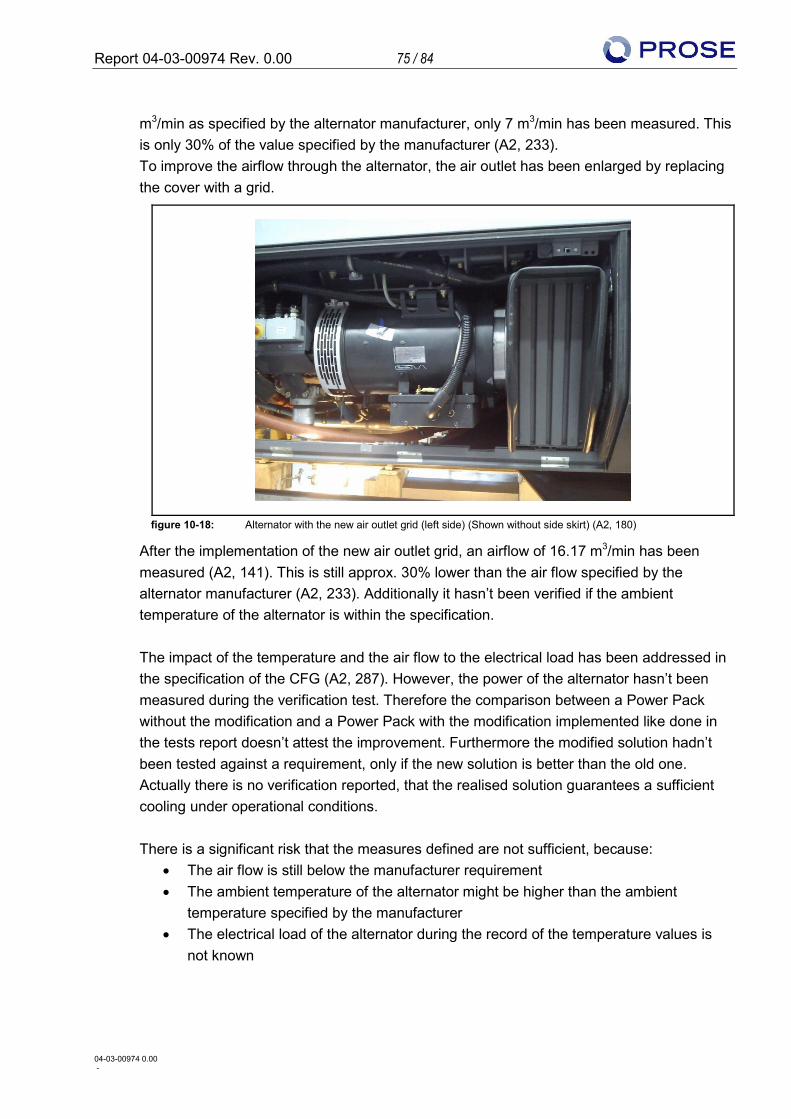
Report 04-03-00974 Rev. 0.00 75 / 84
04-03-00974 0.00 -
m3/min as specified by the alternator manufacturer, only 7 m3/min has been measured. This is only 30% of the value specified by the manufacturer (A2, 233). To improve the airflow through the alternator, the air outlet has been enlarged by replacing the cover with a grid.
figure 10-18: Alternator with the new air outlet grid (left side) (Shown without side skirt) (A2, 180)
After the implementation of the new air outlet grid, an airflow of 16.17 m3/min has been measured (A2, 141). This is still approx. 30% lower than the air flow specified by the alternator manufacturer (A2, 233). Additionally it hasn’t been verified if the ambient temperature of the alternator is within the specification. The impact of the temperature and the air flow to the electrical load has been addressed in the specification of the CFG (A2, 287). However, the power of the alternator hasn’t been measured during the verification test. Therefore the comparison between a Power Pack without the modification and a Power Pack with the modification implemented like done in the tests report doesn’t attest the improvement. Furthermore the modified solution hadn’t been tested against a requirement, only if the new solution is better than the old one. Actually there is no verification reported, that the realised solution guarantees a sufficient cooling under operational conditions. There is a significant risk that the measures defined are not sufficient, because:
• The air flow is still below the manufacturer requirement • The ambient temperature of the alternator might be higher than the ambient
temperature specified by the manufacturer • The electrical load of the alternator during the record of the temperature values is
not known
Report 04-03-00974 Rev. 0.00 76 / 84
04-03-00974 0.00 -
Recommendation: • Investigation of the maximal electrical load in relation to the ambient temperature of
the alternator and the airflow and temperature of the cooling. • Verification of the measured value with the manufacturer requirements. Contact with
the alternator manufacturer might be necessary to clarify possible deviations to the specification.
DC/DC Converter In terms of the faults of the alternator, the DC/DC converter has also been identified as a source of the faults (A2, 373). These DC/DC converters are used to provide status information about the alternator galvanically isolated (A2, 378). The temperature of the DC/DC converter has also been measured during the alternator investigation in relation to temperature. Around the DC/DC converter, a temperature of 85°C has been measured, although some components are designed for a maximum ambient temperature of 60°C (A2, 238). The investigation if the DC/DC converter has an impact on the problems with the generator faults and if the temperature is the root cause, it is still ongoing (A1, 31). The aim is to analyse the impact of the vibration and the temperatures. During the workshop visit we were told, that one of the solution considered is to position the DC/DC converter next to the electronic regulator of the alternator in the air inlet (A1, 31). Based on the measured value of the temperature on the electronic regulator, the mean temperature in the air inlet is around 45°C, but can exceed the 60°C threshold (A2, 289). This is around the maximum ambient temperature allowed for the relays. Therefore it is recommended to find a different solution or to investigate in a more detailed method the air flow and the temperature gradient in the air inlet. Recommendation:
• Thorough analysis of the air flow and the temperature gradient in the air inlet to ensure that the DC/DC card can be placed there or to evaluate a different position
• A proper verification and validation shall be carried out, before the implementation on the fleet to ensure that the root cause has been found and the solution solves the problem.
10.2.4.3 Changes due to incomplete engineering of the power pack
DSB improved the performance of the power pack through various changes that revealed an incomplete engineering. Precise adaptions and optimisation are always part of the design of a complex system. Nevertheless the majority of the failures corrected during the first years of operation of the IC4 fleet should have been detected during the type tests and their solution implemented before the commissioning of the trainset. As a result the reliability and availability of the trains remained poor while the maintenance and engineering resources are occupied and not able to fix these problems in parallel to the daily support for the operation of the trainset. Nevertheless these changes are not seen as critical for the fulfilment of the deployment plan.
Report 04-03-00974 Rev. 0.00 77 / 84
04-03-00974 0.00 -
Below is a quick overview:
• CFG-DSB0032: mechanical protections of the power pack area were added in order to prevent the intrusion of pollution (i.e. autumn leaves). This modification is implemented with successful results.
• CFG-DSB0056: depending of the mounting tolerances and because of the dynamic movements a mechanical contact occurred between the power pack frame (suspended) and the carbody. The carbody was locally adapted in order to ensure a minimal clearance and avoid the transmission of solid vibration from the power pack to the carbody.
• CFG-DSB0065 and CFG-DSB0149: The limiting pressure valve of the air compressor has been successfully modified in two steps in order to increase the reliability of the air pressure production.
• CFG-DSB0091: Modification of the bracket of a brake pipe mounted underframe in order to prevent mechanical interference with the power pack.
• CFG-DSB0092: The hydraulic motor of the generator is mounted suspended on rubber elements to the power pack frame while the generator is rigidly mounted. Because of the ageing and creep of the rubber elements the misalignment of the two components exceeds the acceptable limits (±1mm) with the result that the coupling between the motor and the generator is destroyed. The modification consists of the removing of the rubber elements and a shimming of the hydraulic motor in order to ensure a maximal misalignment of +/-0.5mm.
• CFG-DSB0099: The thermostat for the valve of the passenger heating system was placed in an overly heated environment and was therefore not working properly. The thermostat was moved outside the power pack area which provided reliable functioning.
• CFG-DSB0119: In case of change of direction the axle reversing gear (ARG) supplied by ZF failed sometimes to engage due to tooth-to-tooth interference with the result that no traction was available. A solution to this problem was already available from ZF and implemented on the IC3 (it appears that AB didn’t consider it useful to implement it). The solution was successfully implemented on the IC4 fleet.
• CFG-DSB0128: The exhaust pipe is fixed to the power pack frame by a rubber element which couldn’t withstand the heated environment. The rubber element was successfully replaced by a metal suspension support.
• CFG-DSB0132: The air inlet hose showed weaknesses for withstanding the sucking depression together with the vibration. A new component has been defined with a more rigid material and successfully tested regarding the vibration. Yet the validation of the material in terms of the heated environment of the power pack is missing. We recommend investigating this aspect as a consequences as heat has already been the main issue for several CFG’s.
Report 04-03-00974 Rev. 0.00 78 / 84
04-03-00974 0.00 -
• CFG-DSB0151: The gasket of the oil pump was replaced for a better withstanding of the heated environment
• CFG-DSB0180: The sealing of the inverter was improved. The remaining problem is that a cooling of the inverter is missing and the components inside the inverter are getting too hot. The investigation of this new problem is in progress.
• CFG-DSB0187: Leakage of the exhaust gas occurred because the mounting of the original clamps was unsteady and unreliable. The clamps of the exhaust line were changed and the maintenance instruction was improved.
• CFG-DSB0189: The starting process of the diesel engine requires the relay 5K25 to be closed. The relay 5K25 is active in case different safety related system work proper and the axle reverse gear is in neutral position (Only this information is relevant for starting the engine). Therefore it’s currently not possible to start up the engine if e.g. the trainset has an ATC fault, which is irrelevant for starting up the engine. Due to this the battery could be empty until the problem is fixed and then the battery voltage is too low to start up the engine. The modification consists of obtaining a validation of the neutral position of the axle reverse gear through the TCMS instead of the relay 5K25 resulting in a starting procedure that ensure the same level of safety.
• CFG-DSB0230: In order to reduce the noise in the passenger section of the IC4 trainsets, an insert is installed in the exhaust system which separates the exhaust gases from the two power packs. Gas turbulence is avoided and according to the tests performed (A2, 271) the improvement of noise emission is validated. Nevertheless the modification modifies the flue of the gases and increases the backpressure in the exhaust system by 15%. After investigating the possible consequences of the increased backpressure, DSB decided to proceed to a modification of the exhaust muffler with the aim of reducing the back pressure inside the acceptable limit (see CFG-DSB0272).
• CFG-DSB0245: Wrong speed signal were provided by the anti-sliding system because of poor workmanship on the sonic wheel. The sonic wheels were inspected on the whole fleet and replaced where needed.
• CFG-DSB0246: The wheel diameter is a fixed parameter in the IVECO-SW for the anti-sliding system. The parameter was fixed to 860mm. Because the real diameter of the wheel can be between 800 and 860mm the system could detect an incorrect sliding with worn wheels, because wheels had a lower speed yet without sliding. The parameter was changed to the average value 835mm ensuring a speed deviation inside the tolerances of the anti-sliding system for every wheel diameters.
• CFG-DSB0247: It has been discovered that on some of the ZF mechanical gears the shift parameters “correction factor” used for the calculation of the gearbox input-shaft speed is switched off, resulting in a gear shifting that is uneven on the whole fleet. Further to this CFG, DSB plans to optimise the shift behaviour of the gear box in
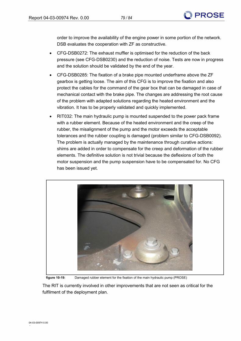
Report 04-03-00974 Rev. 0.00 79 / 84
04-03-00974 0.00 -
order to improve the availability of the engine power in some portion of the network. DSB evaluates the cooperation with ZF as constructive.
• CFG-DSB0272: The exhaust muffler is optimised for the reduction of the back pressure (see CFG-DSB0230) and the reduction of noise. Tests are now in progress and the solution should be validated by the end of the year.
• CFG-DSB0285: The fixation of a brake pipe mounted underframe above the ZF gearbox is getting loose. The aim of this CFG is to improve the fixation and also protect the cables for the command of the gear box that can be damaged in case of mechanical contact with the brake pipe. The changes are addressing the root cause of the problem with adapted solutions regarding the heated environment and the vibration. It has to be properly validated and quickly implemented.
• RIT032: The main hydraulic pump is mounted suspended to the power pack frame with a rubber element. Because of the heated environment and the creep of the rubber, the misalignment of the pump and the motor exceeds the acceptable tolerances and the rubber coupling is damaged (problem similar to CFG-DSB0092). The problem is actually managed by the maintenance through curative actions: shims are added in order to compensate for the creep and deformation of the rubber elements. The definitive solution is not trivial because the deflexions of both the motor suspension and the pump suspension have to be compensated for. No CFG has been issued yet.
figure 10-19: Damaged rubber element for the fixation of the main hydraulic pump (PROSE)
The RIT is currently involved in other improvements that are not seen as critical for the fulfilment of the deployment plan.
Report 04-03-00974 Rev. 0.00 80 / 84
04-03-00974 0.00 -
10.2.4.4 Findings and recommendations
Out of the 25 listed CFGs and current problems it appears that
• 16 of them (64%) are because the engineering of the power pack is not complete, i.e. the engineering of the system is not under control. The definition and implementation of these CFGs are very time consuming yet the improved reliability remains below the expected level because these issues shouldn’t be experienced during operation. Some of these issues reveal deficiencies in the engineering (as for example CFG-DSB0056, CFG-DSB0092, CFG-DSB0126 or more recently CFG-DSB0285) promoting questioning in the layout of the complete system. It is therefore strongly recommended to investigate in details the design of the power pack with the aim of detecting failures before they occur in operation.
• Five of them (20%) are addressing issues that typically occur during operation, i.e. issues that cannot be easily detected during tests (CFG-DSB0065, CFG-DSB0132, CFG-DSB0187, CFG-DSB0189 or CFG-DSB0247). It means that roughly 25% of the resources of the RIT and engineering are effectively doing what they should. It has to be highlighted that for each of these CFG’s the root cause analysis, the requirements, the verification and testing and the validation have to be done accurately in order to experienced steady improvement in reliability.
• 4 of them are critical (CFG-DSB0277, leakage in the fuel pipe, damaged thrust bearing of the crankshaft, cooling of the alternator). All of them require an accurate action plan for the investigation and the definition of the corrective actions. Risks are to be assessed in order to evaluate the possible consequences for the IC4 program.
Recommendations:
• A detailed technical assessment of the power pack is recommended. The power pack went through a comprehensive test program (A2, 242). Nevertheless the reliability and availability problems that occurred during the operation show not only that the power pack was not fully tested when entering in operation but also that important aspects of the design have not been handled properly. For the safe development of the program it is mandatory to strengthen the technical basis of the power pack by detecting possible failures before they appear during operation.
• Because some of the actual issues can have drastic consequences it is recommended that a task force is set up that will be able to investigate and implement solutions for the critical problems within a short timeframe. RIT and engineering will then be able to focus on reliability improvement.
• Some of the errors occur only after running certain mileages. It is recommended to that designated trainsets are prioritised for use in long distance traffic. Therefore five trainsets on the up-to-date configuration shall be designated to run a high mileage in a short period of time.
Report 04-03-00974 Rev. 0.00 81 / 84
04-03-00974 0.00 -
10.2.5 Possible consequences
The current solution on the power pack and the axle box housing is indicating weaknesses this could lead to major design changes:
• Design change leads to new engine, costing about 500,000 DKK per engine, 2 Mio DKK per trainset
• Design change leads to engine retrofit activities, costing about 200,000 DKK per engine, 800,000 DKK per trainset
• Design change leads to new axle box housings, costing about 40,000 DKK per bogie, 200,000 DKK per trainset
The costing is assumed based on experience.
Report 04-03-00974 Rev. 0.00 82 / 84
04-03-00974 0.00 -
11 Differences in conclusion to the Atkins report This chapter give an overview of the differences in relative to the conclusions drawn up in the Atkins report of September 2011 (A2, 001) which has been determined. Today is a completely different situation compared to October 2011, where the Atkins report was elaborated. The last trainsets were completed by end of year 2013. Now the trainsets are in operation collecting more mileages and operational experience. Refer to chapter 6.2.1 the complete organisation has been changed. Refer to the chapter 4.3 of the Atkins report today the IC4PT is part of the DSB-M. In chapter 3.2.3 of the Atkins report an actual ratio in 2011 of 50/50 between SPM and UCM is stated regarding maintenance resources. In reference to chapter 8 advice to adjust the ration to 10/90 is given. The current situation with 15/85 ratio is not the same as stated in the Atkins report. In addition a ratio of 90/10 as stated in the Atkins report is not realistic. Indeed the workshop performance has not been assessed by Atkins. In chapter 5.4.2 of the Atkins report a reliability improvement is predicted. The statement is based on a calculated starting point considering a learning curve. Additionally an assumption of putting a RIT in place has been taken into account. As the RIT has been in operation since mid-2013 and some of the root causes are still unknown there might be a smaller adjustment in time referring to chapter 9.2. However the model stated by Atkins is still valid.
In chapter 3.1.1 of the Atkins report it is concluded that the major systems and major items of equipment fitted to IC4 trainsets are sound and are currently operating reliably.
Unfortunately now this is not the case as identified during the technical risk assessment (Chapter 10):
• Brake system o On 7 November 2011 the Marslev Brake incidence arose. During the
investigation the two problems found by the task force (wrong piping of the parking brake and unequal repartition of the brake force on the axles) were not mentioned
• Axle box housings o No problems have been mentioned although two fractures already existed
(February and December 2010) • Power pack
o 68% of the known CGF’s are because the engineering of the power pack is not complete, i.e. the engineering of the system is not under control.
Report 04-03-00974 Rev. 0.00 83 / 84
04-03-00974 0.00 -
12 Abbreviations, Terminology AA Authority Approval AB Ansaldo Breda (Italy and Danmark) a.c. Alternating Current ATC Automatic Train Control ARG Axle Reversing Gear BCU Brake Control Unit CFG Rebuild and Campaigns to the IC4 and IC2 fleet DMU Diesel Multiple Unit DSB DSB Danske Statsbaner (Danish State Railways) DSB-M DSB Maintenance (DSB Vedligehold A/S) DSB-O DSB Operation DSB-S DSB Sikkerhed (DSB Safety) DTO DSB train reliability monitoring system EMU Electric Multiple Unit FAG Friedrich Fischer public company (of INA-Holding Schaeffler limited partnership) FMEA Failure Mode and Effects Analysis FT Faiveley Transportation FTE Full-Time Equivalent HDB Hydrodynamic Brake IC2 2-car Inter-City diesel-mechanical multiple unit train designed and manufactured by AB IC3 3-car Inter-City diesel-mechanical multiple unit train designed by DSB and ABB Scandia
(now Bombardier Transportation), manufactured by ABB Scandia, and introduced to traffic in 1991
IC4 4-car Inter-City diesel-mechanical multiple unit train designed and manufactured by AB IC4PT IC4 Program Team IDU Integrated Diagnostic Unit (Human-machine interface in each driving cab) KAC Kastrup Airport Copenhagen KPI Key Performance Indicator MDBF Mean Distance Between Failure causing a delay > 5min Mu4 TCMS software version PP Power Pack QMS Quality Management System RAMS Reliability, Availability, Maintainability and Safety RCA Root cause analysis RIT Reliability Improvement Team
SAP Systemanalyse und Programmentwicklung (supplier of spare parts management software)
SBB Swiss Federal Railways SFDD Subsystem Functional and Design Description SPM Scheduled Preventive Maintenance TC Train Computer TCMS Train Computer and Monitoring System TRS Tecnologie nelle Reti e nei Sistemi (sub supplier of AB) TS Trafikstyrelsen (National Safety Authority), Danmark UCM Unscheduled Corrective Maintenance WSP Wheels Slide Protection
Report 04-03-00974 Rev. 0.00 84 / 84
04-03-00974 0.00 -
13 Appendices
ID Content Nb.
pages A1 Journal: Meetings, Interview, Visits 4 A2 Document Reference List 6 A3 ISO 9001:2008 - A4 OHSAS 18001:2007 - A5 ISO 14001:2004 - A6 EN 50126:1999 - A7 EN 50128:2011 -
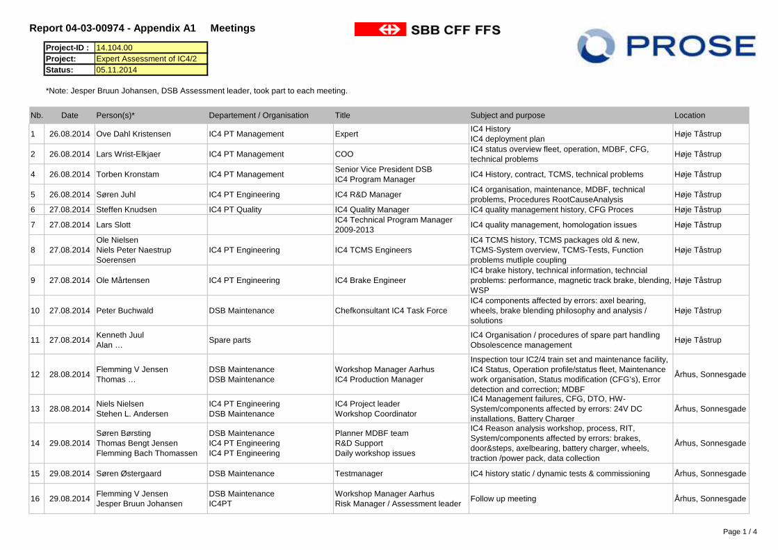
Report 04-03-00974 - Appendix A1 Meetings Project-ID : 14.104.00Project: Expert Assessment of IC4/2 Status: 05.11.2014
Nb. Date Person(s)* Departement / Organisation Title Subject and purpose Location
1 26.08.2014 Ove Dahl Kristensen IC4 PT Management ExpertIC4 HistoryIC4 deployment plan
Høje Tåstrup
2 26.08.2014 Lars Wrist-Elkjaer IC4 PT Management COOIC4 status overview fleet, operation, MDBF, CFG, technical problems
Høje Tåstrup
4 26.08.2014 Torben Kronstam IC4 PT ManagementSenior Vice President DSBIC4 Program Manager
IC4 History, contract, TCMS, technical problems Høje Tåstrup
5 26.08.2014 Søren Juhl IC4 PT Engineering IC4 R&D ManagerIC4 organisation, maintenance, MDBF, technical problems, Procedures RootCauseAnalysis
Høje Tåstrup
6 27.08.2014 Steffen Knudsen IC4 PT Quality IC4 Quality Manager IC4 quality management history, CFG Proces Høje Tåstrup
7 27.08.2014 Lars Slott IC4 Technical Program Manager 2009-2013
IC4 quality management, homologation issues Høje Tåstrup
8 27.08.2014Ole NielsenNiels Peter Naestrup Soerensen
IC4 PT Engineering IC4 TCMS EngineersIC4 TCMS history, TCMS packages old & new, TCMS-System overview, TCMS-Tests, Function problems mutliple coupling
Høje Tåstrup
9 27.08.2014 Ole Mårtensen IC4 PT Engineering IC4 Brake EngineerIC4 brake history, technical information, techncial problems: performance, magnetic track brake, blending, WSP
Høje Tåstrup
10 27.08.2014 Peter Buchwald DSB Maintenance Chefkonsultant IC4 Task ForceIC4 components affected by errors: axel bearing, wheels, brake blending philosophy and analysis / solutions
Høje Tåstrup
11 27.08.2014Kenneth JuulAlan …
Spare partsIC4 Organisation / procedures of spare part handlingObsolescence management
Høje Tåstrup
12 28.08.2014Flemming V JensenThomas …
DSB MaintenanceDSB Maintenance
Workshop Manager AarhusIC4 Production Manager
Inspection tour IC2/4 train set and maintenance facility, IC4 Status, Operation profile/status fleet, Maintenance work organisation, Status modification (CFG’s), Error detection and correction; MDBF
Århus, Sonnesgade
13 28.08.2014Niels NielsenStehen L. Andersen
IC4 PT EngineeringDSB Maintenance
IC4 Project leaderWorkshop Coordinator
IC4 Management failures, CFG, DTO, HW-System/components affected by errors: 24V DC installations, Battery Charger
Århus, Sonnesgade
14 29.08.2014Søren BørstingThomas Bengt JensenFlemming Bach Thomassen
DSB MaintenanceIC4 PT EngineeringIC4 PT Engineering
Planner MDBF teamR&D SupportDaily workshop issues
IC4 Reason analysis workshop, process, RIT, System/components affected by errors: brakes, door&steps, axelbearing, battery charger, wheels, traction /power pack, data collection
Århus, Sonnesgade
15 29.08.2014 Søren Østergaard DSB Maintenance Testmanager IC4 history static / dynamic tests & commissioning Århus, Sonnesgade
16 29.08.2014Flemming V JensenJesper Bruun Johansen
DSB MaintenanceIC4PT
Workshop Manager AarhusRisk Manager / Assessment leader
Follow up meeting Århus, Sonnesgade
*Note: Jesper Bruun Johansen, DSB Assessment leader, took part to each meeting.
Page 1 / 4
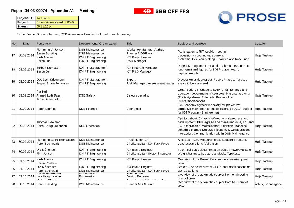
Report 04-03-00974 - Appendix A1 Meetings Project-ID : 14.104.00Project: Expert Assessment of IC4/2 Status: 05.11.2014
Nb. Date Person(s)* Departement / Organisation Title Subject and purpose Location
*Note: Jesper Bruun Johansen, DSB Assessment leader, took part to each meeting.
17 08.09.2014
Flemming V. JensenSøren BørstingNiels NielsenSøren Juhl
DSB MaintenanceDSB MaintenanceIC4 PT EngineeringIC4 PT Engineering
Workshop Manager AarhusPlanner MDBF teamIC4 Project leaderR&D Manager
Participation to RIT weekly meetingdiscussions about actual / current problems, Decision-making, Priorities and base lines
Høje Tåstrup
18 08.09.2014Torben KronstamSøren Juhl
IC4 PT ManagementIC4 PT Engineering
IC4 Program ManagerIC4 R&D Manager
Project Management, Financial schedule (short- and long-term) and figures for IC4 Program team, deployment plan
Høje Tåstrup
19 08.09.2014Ove Dahl KristensenJesper Bruun Johansen
IC4 PT ManagementIC4 PT Engineering
ExpertRisk Manager / Assessment leader
Discussion draft progress Report Phase 1, focused area’s to be assessed
Høje Tåstrup
20 09.09.2014Per HeinAhmed Lutfi ØzerJanie Behrensdorf
DSB Safety Safety specialist
Organisation, Interface to IC4PT, maintenance and operation departments, Assessors, National authority (Trafikstyrelsen), Schedule, Process flow CFG’s/modifications
Høje Tåstrup
21 09.09.2014 Peter Schmidt DSB Finance EconomistIC4 Economy agreed financially for preventive, corrective maintenance, modifications till 2019, Budget for IC4 Program (Engineering)
Høje Tåstrup
22 09.09.2014Thomas EdelmanHans Sørup Jakobsen DSB Operation
Opinion about IC4 vehicle/fleet, actual progress and development; KPIs agreed and measured (IC4, IC3 and IC2) Operation & Maintenance, Priorities / baseline schedule change Dec 2014 focus IC4, Collaboration, Interaction, Communication within DSB Maintenance
Høje Tåstrup
23 30.09.2014Flemming Bach ThomassenPeter Buchwaldt
DSB MaintenanceDSB Maintenance
Projektleiter IC4Chefkonsultant IC4 Task Force
Axle Box: RCA, Measurements, Solution Structure,Load assumptions, Validation
Høje Tåstrup
24 30.09.2014Ole MårtensenFinn Jensen
IC4 PT EngineeringIC4 PT Engineering
IC4 Brake EngineerChefkonsultant Systemintegrator
Technical basic documentation basis known/available: Weight balance, Structure analysis, Typetests
Høje Tåstrup
25 01.10.2014Niels Nielson Søren Poulsen
IC4 PT Engineering IC4 Project leader Overview of the Power Pack from engineering point of view
Høje Tåstrup
26 01.10.2014Ole MårtensenPeter Buchwald
IC4 PT EngineeringDSB Maintenance
IC4 Brake EngineerChefkonsultant IC4 Task Force
Brakes – Specific current CFG’s and modifications as well as actions
Høje Tåstrup
27 02.10.2014Søren Østergaard Lars Kragh NykjærMichael Obelix
EngineeringEngineeringMaintenance
TestmanagerDesign EngineerTeam leader TCMS Transfer
Overview of the automatic coupler from engineering point of view
Høje Tåstrup
28 08.10.2014 Soren Børsting DSB Maintenance Planner MDBF teamOverview of the automatic coupler from RIT point of view
Århus, Sonnesgade
Page 2 / 4
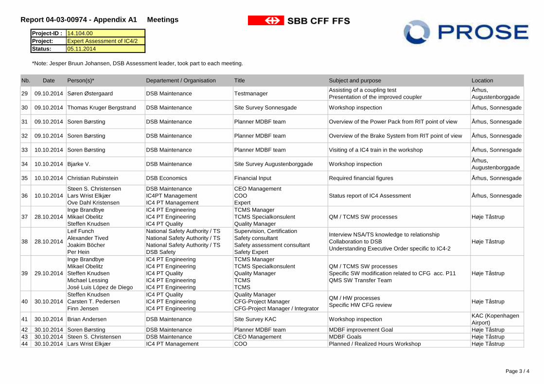
Report 04-03-00974 - Appendix A1 Meetings Project-ID : 14.104.00Project: Expert Assessment of IC4/2 Status: 05.11.2014
Nb. Date Person(s)* Departement / Organisation Title Subject and purpose Location
*Note: Jesper Bruun Johansen, DSB Assessment leader, took part to each meeting.
29 09.10.2014 Søren Østergaard DSB Maintenance TestmanagerAssisting of a coupling testPresentation of the improved coupler
Århus, Augustenborggade
30 09.10.2014 Thomas Kruger Bergstrand DSB Maintenance Site Survey Sonnesgade Workshop inspection Århus, Sonnesgade
31 09.10.2014 Soren Børsting DSB Maintenance Planner MDBF team Overview of the Power Pack from RIT point of view Århus, Sonnesgade
32 09.10.2014 Soren Børsting DSB Maintenance Planner MDBF team Overview of the Brake System from RIT point of view Århus, Sonnesgade
33 10.10.2014 Soren Børsting DSB Maintenance Planner MDBF team Visiting of a IC4 train in the workshop Århus, Sonnesgade
34 10.10.2014 Bjarke V. DSB Maintenance Site Survey Augustenborggade Workshop inspectionÅrhus, Augustenborggade
35 10.10.2014 Christian Rubinstein DSB Economics Financial Input Required financial figures Århus, Sonnesgade
36 10.10.2014Steen S. Christensen Lars Wrist ElkjærOve Dahl Kristensen
DSB MaintenanceIC4PT ManagementIC4 PT Management
CEO ManagementCOOExpert
Status report of IC4 Assessment Århus, Sonnesgade
37 28.10.2014Inge BrandbyeMikael ObelitzSteffen Knudsen
IC4 PT EngineeringIC4 PT EngineeringIC4 PT Quality
TCMS ManagerTCMS SpecialkonsulentQuality Manager
QM / TCMS SW processes Høje Tåstrup
38 28.10.2014
Leif FunchAlexander TivedJoakim BöcherPer Hein
National Safety Authority / TSNational Safety Authority / TSNational Safety Authority / TSDSB Safety
Supervision, CertificationSafety consultantSafety assessment consultantSafety Expert
Interview NSA/TS knowledge to relationshipCollaboration to DSBUnderstanding Executive Order specific to IC4-2
Høje Tåstrup
39 29.10.2014
Inge BrandbyeMikael ObelitzSteffen KnudsenMichael LessingJosé Luis López de Diego
IC4 PT EngineeringIC4 PT EngineeringIC4 PT QualityIC4 PT EngineeringIC4 PT Engineering
TCMS ManagerTCMS SpecialkonsulentQuality ManagerTCMSTCMS
QM / TCMS SW processesSpecific SW modification related to CFG acc. P11QMS SW Transfer Team
Høje Tåstrup
40 30.10.2014Steffen KnudsenCarsten T. PedersenFinn Jensen
IC4 PT QualityIC4 PT EngineeringIC4 PT Engineering
Quality ManagerCFG-Project ManagerCFG-Project Manager / Integrator
QM / HW processesSpecific HW CFG review
Høje Tåstrup
41 30.10.2014 Brian Andersen DSB Maintenance Site Survey KAC Workshop inspectionKAC (Kopenhagen Airport)
42 30.10.2014 Soren Børsting DSB Maintenance Planner MDBF team MDBF improvement Goal Høje Tåstrup43 30.10.2014 Steen S. Christensen DSB Maintenance CEO Management MDBF Goals Høje Tåstrup44 30.10.2014 Lars Wrist Elkjær IC4 PT Management COO Planned / Realized Hours Workshop Høje Tåstrup
Page 3 / 4
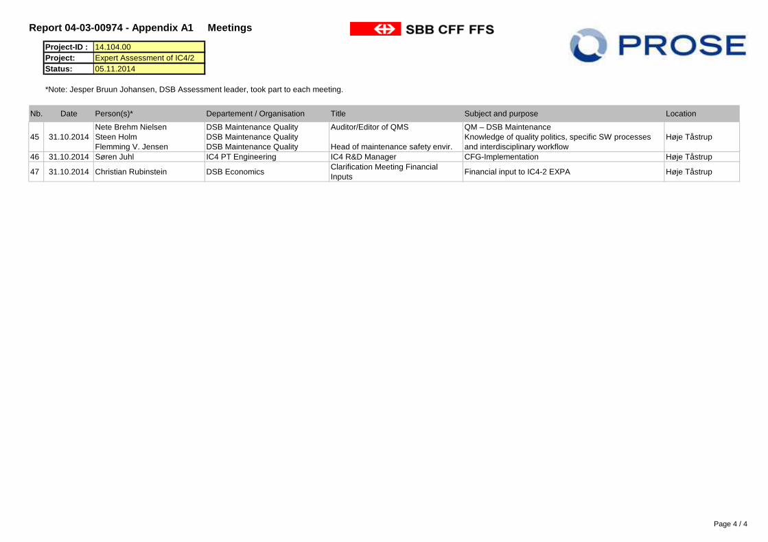
Report 04-03-00974 - Appendix A1 Meetings Project-ID : 14.104.00Project: Expert Assessment of IC4/2 Status: 05.11.2014
Nb. Date Person(s)* Departement / Organisation Title Subject and purpose Location
*Note: Jesper Bruun Johansen, DSB Assessment leader, took part to each meeting.
45 31.10.2014Nete Brehm NielsenSteen HolmFlemming V. Jensen
DSB Maintenance QualityDSB Maintenance QualityDSB Maintenance Quality
Auditor/Editor of QMS
Head of maintenance safety envir.
QM – DSB MaintenanceKnowledge of quality politics, specific SW processes and interdisciplinary workflow
Høje Tåstrup
46 31.10.2014 Søren Juhl IC4 PT Engineering IC4 R&D Manager CFG-Implementation Høje Tåstrup
47 31.10.2014 Christian Rubinstein DSB EconomicsClarification Meeting Financial Inputs
Financial input to IC4-2 EXPA Høje Tåstrup
Page 4 / 4
Report 04-03-00974 - Appendix A2 Document Reference List
Project-ID :Project:
PROSE PROJECT internal
document number
Obsolete Document Name Document ID
IssuerRevisi
onDate
Language
Issuer FormatDate
receiptreceipt by
Sourcereceipt
Type CategoryPROSE
Document IDContent
001 ATKINS IC4-IC2 Review - Background Report 5105273.001/002 1 19.10.2011 E ATKINS pdf E-Mail DSB R Technical 04-13-01397-E00002 DB Untersuchung zu Lager- und Dämpferschäden an den Fahrzeugen IC2 und IC4 der DSB 14-17462-DSB-140312-01 1.10 04.07.2014 G DB pdf E-Mail DSB R Technical 04-13-01392-E00
003Extract from the report to the Public Accounts Committee on DSB’s procurement and completion of IC4 and IC2 trains
01.06.2012 E RIGSREVISIONEN pdf E-Mail DSB M Information 04-13-01415-E00REPORT ON DSB’S PROCUREMENT AND COMPLETI O N O F IC4 AN D IC2 TRAINS
004 DSB Deployment for IC4 14.08.2014 D DSB pptx E-Mail DSB P Reliability005 Preliminary info to PROSE Ltd IC4-2 Exp assess 2014-1 n.a. n.a. E DSB docx E-Mail DSB M Information006 DSB SAFETY CASE For IC4 Litra MG P000271054 8AE 23.01.2014 E DSB docx E-Mail DSB R Technical including train overview007 Technical specification for PowerPack PMT-AA01J3C 2 29.04.2002 E AB pdf E-Mail DSB R Technical008 IC4 general Layout drawing 0 23.10.2002 E AB pdf E-Mail DSB D Technical009 AA02WTL - IC2 GENERAL LAYOUT 1 23.05.2003 E AB pdf E-Mail DSB D Technical010 IC4 design info for Proce Phase 1 n.a. n.a. E DSB docx 21.08.2014 E-Mail DSB M Technical011 List of SFDDs (Subsystem Functional and Design Description) 20.08.2014 E DSB pdf 21.08.2014 E-Mail DSB R Technical012 SFDD DSD (Driver safety device) AA03Y1K 6 12.09.2007 E AB doc 21.08.2014 E-Mail DSB R Technical013 IC4 Authority approval process documentation delivery status AQU IO/045 22AI 03.02.2014 E DSB pdf 22.08.2014 E-Mail DSB R Technical014 DSB – IC4/2 EXPA - Interviews 25.08.2014 E DSB docx 25.08.2014 E-Mail DSB M Organisational
015IC4 Programme Top DownMeeting with Management 26.08.2014 IC4-2 EXPA
27.08.2014 E/D DSB pdf 28.08.2014 E-Mail DSB P Information
016 Oganisation as pr 1 september D DSB pdf 28.08.2014 E-Mail DSB P Organisational017 Management meeting Time line highlights E DSB docx 28.08.2014 E-Mail DSB R Information018 IC4 Brakeblending D DSB pdf 28.08.2014 E-Mail DSB P Technical019 Udmattelse Mekanik (Measurements Damper and axlebox) E/G DSB pptx 28.08.2014 E-Mail DSB P Technical020 Arbejdsinstruktion CFG-DSB0221 HVAC Førerrum fjernelse af blænde til vameveksler P000262259 01 24.06.2013 D DSB doc 28.08.2014 E-Mail DSB R Technical021 CFG-DSB0221 HVAC Førerrum fjernelse af blænde til varmeveksler P000246734 01 14.05.2013 D DSB doc 28.08.2014 E-Mail DSB R Technical022 CSM Ekspertvurdering CFG-DSB0221 HVAC Førerrum fjernelse af blænde til varmeveksler P000246963 05.06.2013 D DSB doc 28.08.2014 E-Mail DSB R Technical023 Godkendelseserklæring vedr hasardidentifikation - CFG- DSB0221_signeret P000259314 1 19.06.2013 D DSB pdf 28.08.2014 E-Mail DSB R Technical024 Konstruktionsgranskningsrapport_integrator HVAC førerrum fjernelse af blændeCFG DSB0221 P000274307 01 04.12.2013 D DSB doc 28.08.2014 E-Mail DSB R Technical025 Operatør selvkontrol CFG-DSB0221 HVAC Førerrum fjernelse af blænde til varmeveksler P000262260 01 25.06.2013 D DSB doc 28.08.2014 E-Mail DSB R Technical
026 Systembeskrivelse og Kravspecifikantion CFG-DSB0221 HVAC Førerrum fjernelse af blænde til varmeveksle P000246939 01 13.05.2013 D DSB doc 28.08.2014 E-Mail DSB R Technical
027 Validerings raport integrator HVAC Førerrum fjernelse af blænde CFG DSB 0221 P000274317 01 08.12.2013 D DSB doc 28.08.2014 E-Mail DSB R Technical028 Verifikationsrapport CFG-DSB0221 P000271728 01 02.09.2013 D DSB doc 28.08.2014 E-Mail DSB R Technical029 IC2 - km 31.08.2014 D DSB xlsx 01.10.2014 E-Mail DSB M Information030 IC4 - km 31.10.2014 D DSB xlsx 19.11.2014 E-Mail DSB M Information032 Referat møde 3. IC4 SG 21.08.2014 D DSB docx 28.08.2014 E-Mail DSB M Information minutes of meetings from the IC4 Steering Group meeting033 MG MDBF jun 13 jul 14 D DSB xlsx 29.08.2014 E-Mail DSB M Information034 SFDD TC (Train Computer) AA040JH 13 27.05.2014 E DSB pdf 01.09.2014 E-Mail DSB R Technical035 Prose møde 26 aug 2014 26.08.2014 E DSB ppt 05.09.2014 E-Mail DSB P Information036 IC4-2 DSB Interviewees-W37-5 04.09.2014 E DSB docx 04.09.2014 E-Mail DSB M Organisational037a Brake Equipment SA-3992 (AA01K6D) AP 10.04.2009 E FT pdf 05.09.2014 E-Mail DSB D Technical037b Brake Equipment Vehicle M1C SA-3993 (AA01K6D) AP 10.04.2009 E FT pdf 05.09.2014 E-Mail DSB D Technical037c Brake Equipment Vehicle T2HK-T3 SA-3994 (AA01K6D) AP 10.04.2009 E FT pdf 05.09.2014 E-Mail DSB D Technical037d Brake Equipment Vehicle M4C SA-4144 (AA01K6D) AP 10.04.2009 E FT pdf 05.09.2014 E-Mail DSB D Technical
38 General Description Brake Equipment for DMU GTA IC4 Denmark AA01KD4 10 10.04.2009 E FT pdf 05.09.2014 E-Mail DSB R Technical39 Brake Disc - Thermal and wear calculation AA01VBC 02 24.07.2002 E KB pdf 05.09.2014 E-Mail DSB R Technical40 DMU IC4 SUBSYSTEM FUNCTIONAL AND DESIGN DESCRIPTION AA03Y1U 13 09.10.2008 E AB pdf 05.09.2014 E-Mail DSB S Technical41 Traction brake functional schematic diagram AA04502 01 14.12.2004 E AB pdf 05.09.2014 E-Mail DSB D Technical42 Emergency Brake Calculation TA27304-75 04 20.01.2005 E KB pdf 05.09.2014 E-Mail DSB R Technical43 Parking brake calculation TA27304-72 05 20.01.2005 E KB pdf 05.09.2014 E-Mail DSB R Technical44 Security brake calculation TA27304-77 04 20.01.2005 E KB pdf 05.09.2014 E-Mail DSB R Technical45 Service brake calculation (Pneumatic + E.P.) TA27304-76 04 20.01.2005 E KB pdf 05.09.2014 E-Mail DSB R Technical46 Service brake calculation (Pneumatic + 100% H.D. with E.P.) TA27304-79 04 20.01.2005 E KB pdf 05.09.2014 E-Mail DSB R Technical47 SFDD Brake AA03Y1U 13 09.10.2008 E AB pdf 05.09.2014 E-Mail DSB R Technical48 SFDD Traction AA03Y1M 10 17.10.2008 E AB doc 05.09.2014 E-Mail DSB R Technical49 SFDD Desk Key AA03Y1P 4 29.10.2008 E AB pdf 05.09.2014 E-Mail DSB R Technical50 SFDD DLU (DATA LOGGER UNIT ) AA03Y1Y 4/AA 14.09.2012 E AB doc 05.09.2014 E-Mail DSB R Technical51 SFDD ATC (Automatic Train Control System) AA03Y1L 3 10.10.2008 E AB doc 05.09.2014 E-Mail DSB R Technical52 SFDD ARG (Axle Reverse Gear) AA040JF 5 13.11.2007 E AB doc 05.09.2014 E-Mail DSB R Technical53 SFDD Powering AA03Y1Z 7AA 18.11.2008 E AB pdf 05.09.2014 E-Mail DSB R Technical54 SFDD Radio AA03Y1V 2 03.05.2006 E AB doc 05.09.2014 E-Mail DSB R Technical55 SFDD Doors AA03Y1T 4/AC 29.01.2014 E AB doc 05.09.2014 E-Mail DSB R Technical56 SFDD PIS (Passenger Information System) AA040JJ 5 06.02.2009 E AB doc 05.09.2014 E-Mail DSB R Technical57 SFDD TRIT (DSB wireless transmission system) AA040JK 4 25.11.2008 E AB doc 05.09.2014 E-Mail DSB R Technical
58SFDD HVAC (Heating, Ventilation and Air Conditionfor Passengers Compartments)
AA03Y1R 6/AC 15.03.2013 E AB doc 05.09.2014 E-Mail DSB R Technical
59SFDD HVAC (Heating, Ventilation and Air Conditionfor Drivers Cabin)
AA03Y1X 6/AB 22.07.2014 E AB doc 05.09.2014 E-Mail DSB R Technical
60 SFDD IDU (Integrated diagnostic unit) AA05HEU 24 23.07.2013 E AB pdf 05.09.2014 E-Mail DSB R Technical61 SFDD Toilettes AA040JR 2 31.10.2008 E AB doc 05.09.2014 E-Mail DSB R Technical62 SFDD Coupling AA03Y1N 7 27.03.2009 E AB doc 05.09.2014 E-Mail DSB R Technical63 SFDD INDOOR, CAB AND EXTERNAL LIGHTING AA03Y1W 5 31.10.2008 E AB doc 05.09.2014 E-Mail DSB R Technical64 SFDD Miscellaneous AA040JP 6 03.11.2008 E AB doc 05.09.2014 E-Mail DSB R Technical65 DMU Danimarca - General Winter Configuration Layout 4 14.09.2009 E AB pdf 29.08.2014 Hardcopy DSB D Technical
Latest registered date of receipt: 02.12.201414.104.00Expert Assessment of IC4/2
Page 1 / 6
Report 04-03-00974 - Appendix A2 Document Reference List
Project-ID :Project:
PROSE PROJECT internal
document number
Obsolete Document Name Document ID
IssuerRevisi
onDate
Language
Issuer FormatDate
receiptreceipt by
Sourcereceipt
Type CategoryPROSE
Document IDContent
Latest registered date of receipt: 02.12.201414.104.00Expert Assessment of IC4/2
66 DMU IC4 - Underframe Layout 3 14.03.2002 E AB pdf 29.08.2014 Hardcopy DSB D Technical67 DMU IC4 - Devices Layout on the Bogies 3 28.02.2003 E AB pdf 29.08.2014 Hardcopy DSB D Technical68 DMU IC4 - Schema Bus di Treno / Train Bus Diagram 0 15.07.2004 E AB pdf 29.08.2014 Hardcopy DSB D Technical69 HW CONFIGURATION TRAIN MONITORING CONTROL SYSTEM DMU IC4 07 16.12.2009 I AB pdf 29.08.2014 Hardcopy DSB D Technical
70 RIT_dagligopfølgning_TDO 28.01.2014 D DSB pdf 08.09.2014 E-Mail DSB M OrganisationalDescribes the daily progress TDO (Technical Operation Follow-up) for RIT (Realibility improvment team) responsibilities
71 RIT_dagligopfølgning_TDO_swim 28.01.2014 D DSB pdf 08.09.2014 E-Mail DSB M OrganisationalProcess flow of daily progress of TDO (Technical Operation Follow-up) and RIT (Realibility improvment team)
72 RIT_Processen 28.01.2014 D DSB pdf 08.09.2014 E-Mail DSB M Organisational Process of RIT (Realibility improvment team)73 RIT_Processen_swim 28.01.2014 D DSB pdf 08.09.2014 E-Mail DSB M Organisational Process flow of RIT (Realibility improvment team)74 Priotet 0-stillinger 05-09-14 05.09.2014 D DSB xlsx 08.09.2014 E-Mail DSB M Technical Workshop Top 10 implementation prioritizing at workshop 75 Changes in existing vehicles - Flowchart for the approval process E DSB pptx 09.09.2014 E-Mail DSB P Organisational76 Tilladelse til kørsel med IC4 og IC2 (P14) 2 23.07.2014 D DSB pdf 09.09.2014 E-Mail DSB M Organisational Process trains permission to drive after changing trains77 Bogier og løbetøj 2000 / 230 C03 17.07.2014 D DSB pdf 09.09.2014 E-Mail DSB S Maintenance Bogie maintenance instruction78 IC4/IC2 CAPEX - wrap up from interview 10.09.2014 E DSB pdf 11.09.2014 E-Mail DSB M Information79 Presentation of TCMS Software Pack-2.1 and Pack-2.2a ver. 2 E DSB ppt 12.09.2014 E-Mail DSB P Technical80 IDU Pack 2.1 Baseline AA0860H 15 21.06.2013 E AB pdf 12.09.2014 E-Mail DSB S Technical81 TCMS Pack 2.1 Baseline 12_08 AA087RP 09 08.08.2013 E AB pdf 12.09.2014 E-Mail DSB S Technical82 GTW Pack 2.1 Baseline 04 AA087RR 05 11.06.2013 E AB pdf 12.09.2014 E-Mail DSB S Technical83 IDU Pack 2.2.a Baseline Package 2.2.a AA0860H 25 19.04.2014 E AB pdf 12.09.2014 E-Mail DSB S Technical84 Presentation of TCMS Software Mu4 (Mu3+) E DSB ppt 16.09.2014 E-Mail DSB P Technical85 IDU Pack Mu4 Baseline 27 package Multiple 4 AA087ZY 5 14.07.2014 E AB pdf 12.09.2014 E-Mail DSB S Technical86 TCMS Pack Mu4 Baseline 15 Package Mu4 AA087ZX 4 14.07.2014 E AB pdf 12.09.2014 E-Mail DSB S Technical87 GTW Pack Mu4 Baseline 05 Package Multiple4 AA087ZZ 3 14.07.2014 E AB pdf 12.09.2014 E-Mail DSB S Technical
88 Execution version Sub-Appendix 11.3 Requirement Spec Software Package IC4 2 E DSB pdf 12.09.2014 E-Mail DSB S Technicalcontractual requirements due to specification is under development (specifications not yet finalized)
89 Execution version Sub-Appendix 11.6 Requirement Spec Software Package IC2 Porting to IC4 Level E DSB pdf 12.09.2014 E-Mail DSB S Technicalcontractual requirements due to specification is under development (specifications not yet finalized)
90 DSB Deployment plan 2019 for IC4 16.09.2014 E DSB pptx 16.09.2014 E-Mail DSB P Reliability91 List of CFG implemented on each Trainset 16.09.2014 D DSB xlsx 16.09.2014 E-Mail DSB M Technical92 Executive Order no. 56 on the Approval of Railway Vehicles 24.01.2013 E NSA pdf n.a. n.a. n.a. S Approval93 DSB Deployment plan 2016 – 2030 08.09.2014 D DSB pptx 17.09.2014 E-Mail DSB P Information94 Kravspecifikation CFGDSB-0161(P000231289) P000231289 1 04.07.2012 D DSB pdf 23.09.2014 E-Mail DSB R Technical95 CFG0167 Schedule B Requirement specification - front gaiter CR4(P000238613) P000238613 1 27.09.2012 E DSB pdf 23.09.2014 E-Mail DSB S Technical96 CFG0168 Kravspec - TC håndtering front gaiter(P000232610) P000232610 09.07.2013 D DSB pdf 23.09.2014 E-Mail DSB R Technical97 CFG0169 kravspec - elkasser samtidigt(P000233766) P000233766 2 09.07.2013 D DSB pdf 23.09.2014 E-Mail DSB R Technical98 Justering af el-kasser(P000246037) 1400‐031 1 12.06.2012 D DSB pdf 23.09.2014 E-Mail DSB W Technical99 SFDD Manual Coupler(P000272818) FE02P31000B 5 04.06.2013 E AB doc 25.09.2014 E-Mail DSB S Technical100 TCMS experience list 7.15(P000270324) P000270324? 7_15 05.10.2012 E unclear xlsx 25.09.2014 E-Mail DSB S Technical101 TCMS pack 2.1 Single Static Test Procedure Rev.3(P000254148) VER/VPT AA087R7 3 11.06.2013 E AB pdf 25.09.2014 E-Mail DSB S Technical102 Kravspecifikation drænhul i stik CFG-DSB0255 17.07.2014 D DSB doc 26.09.2014 E-Mail DSB S Technical103 Kravspecifikation CFG-DSB0250(P000275380) P000275380 20.01.2014 D DSB doc 26.09.2014 E-Mail DSB S Technical104 Kravspec Reco antenneflytning CFG-DSB0113(P000230677) P000230677 1 27.12.2014 D DSB pdf 26.09.2014 E-Mail DSB S Technical105 TCMS pack 2 Findings assessement by AB and DSB final 7-7-2011(P000219399) P000219399 19 n.d. E n.d. xlsx 26.09.2014 E-Mail DSB S Technical106 Not used107 TIP IC4 plan - V2 D DSB xlsm 17.09.2014 E-Mail DSB M Information108 Design and development of hardware changes to trains IC4-QM-P10 P10.10 2.12 21.07.2014 D DSB pdf 19.09.2014 E-Mail DSB R Organisational109 Design and development of software modifications to trains IC4-QM-P11 P11 1.11 19.08.2014 D DSB pdf 19.09.2014 E-Mail DSB R Organisational110 Implementation of modifications to the IC2 / IC4 trains IC4-QM-P12 P12 2.3 29.08.2014 D DSB pdf 19.09.2014 E-Mail DSB R Organisational111 Teknikmøde - Technical meeting 19092014 19.09.2014 D DSB ppt 23.09.2014 E-Mail DSB P Reliability Monthly steering comitee meeting (prioritise CGF)112 Cenelec kode IC4 Model 1 30.10.2006 E pdf 24.09.2014 E-Mail DSB S Technical113 CFG info til PROSE_version update AF 17-10 - 05-11-2014 05.11.2014 D DSB xlsx 05.11.2014 E-Mail DSB M Technical last version delivered114 DMU IC4 NT weight status (train nb.14) AA07LKZ R0 27.04.2008 E AB xps 26.09.2014 E-Mail DSB R Technical115 DMU IC4 PTO Train 22 weight status (P000163009) AA084EC 00 25.03.2009 E AB pdf 26.09.2014 E-Mail DSB R Technical116 Weight handleing trainset 10 AA05HX1 1 04.03.2006 I AB xps 26.09.2014 E-Mail DSB R Technical
117Lower Part of Axlebox Z-176466 (040803) –Stress Analysis for Lower Part under DamperLoads – Project IC4 – DSB, Ansaldobreda
11.03.2011 E FAG pdf 26.09.2014 E-Mail DSB R Technical
118 Statement, DB Mindens report in relation to AB's measurements 27.08.2014 D DSB docx 26.09.2014 E-Mail DSB R Technical
119 Action plan Axle Boxes addressed 27.08.2014 D DSB docx 26.09.2014 E-Mail DSB R TechnicalDraft Action Plan for IC4 axle boxes justified by DB Minden report, compared to AB's measurements on the train and own statistics on the train.
120 IC4-2 PROSE-DSB Interview for Week 40-2014 26.09.2014 E DSB docx 26.09.2014 E-Mail DSB M Organisational
121DMU – IC4 MEASUREMENT ACTIVITY ONJOURNAL BOXES OF IC4 MOTOR BOGIE IN SERVICE
00 03.07.2014 E AB pdf 26.09.2014 E-Mail DSB R Technical
122 R2-Sub-Appendix 6.4a Propulsion Package 0 20.11.2000 E AB pdf 29.09.2014 E-Mail DSB S Technical Tender documentation: Description of the propulsion package123 Technical Description Master Controller DT-451755 C 27.02.2004 E Sab Wabco pdf 29.09.2014 E-Mail DSB S Technical Technical specification Master Controller124 Power Pack Procedure 428_LG_DP_02_10 3.2 14.11.2007 E ELTRAC pdf 29.09.2014 E-Mail DSB S Technical Project documentation Power Pack Procedure125 ENGINE TORQUE CALCULATION 428_LG_DP_01_04 1 15.11.2002 E ELTRAC pdf 29.09.2014 E-Mail DSB S Technical Project documentation: Engine torque calculation126 ELECTRIC LOADS ESTIMATION AA037LG 1 11.11.2003 E AB pdf 29.09.2014 E-Mail DSB S Technical Electric Loads estimation127 Afdrejning oversigt D DSB xlsx 30.09.2014 E-Mail DSB R Technical Overview of the wheel reprofiling128 140829 WILD Lillebælt 29.08.2014 D DSB pptx 30.09.2014 E-Mail DSB P Technical Presentation of WILD Control System (Wheel Loads on track)129 Taskforce IC4 brems 2014 - 19 sep - 1 19.09.2014 D DSB ppt 30.09.2014 E-Mail DSB P Technical Action plan brake
Page 2 / 6
Report 04-03-00974 - Appendix A2 Document Reference List
Project-ID :Project:
PROSE PROJECT internal
document number
Obsolete Document Name Document ID
IssuerRevisi
onDate
Language
Issuer FormatDate
receiptreceipt by
Sourcereceipt
Type CategoryPROSE
Document IDContent
Latest registered date of receipt: 02.12.201414.104.00Expert Assessment of IC4/2
130 Preventive maintenance activities for bogies 2000-ic4-230 A02 12.09.2014 E DSB AB pdf 18.09.2014 E-Mail DSB W Maintenance
131 Weight - Wheel load measurements trainset 15 07.04.2014 I DSB pdf 01.10.2014 E-Mail DSB R TechnicalIC4 transet no.15 after DSB has rebuild the train for the test with the TCMS pack 2.1. Weight and axel load within the demands in routine test (DRDT 03)
132 DRDT3 MG5615 07.04.2014 I DSB pdf 01.10.2014 E-Mail DSB R Technical
133DSAT 16 DYNAMIC PERFORMANCE STARTING AND ACCELATION AT TARA LOAD (P000203267) trainset 01
AA02JE0 00 06.04.2005 E AB pdf 01.10.2014 E-Mail DSB R Technical
134DSAT 17 DYNAMIC PERFORMANCE STARTING AND ACCELATION AT FULL LOAD (P000203270) trainset 01
AA02JEs 00 21.04.2005 E AB pdf 01.10.2014 E-Mail DSB R Technical
135 DFAT 1 CARBODY STRUCTURAL TEST(P000204234) AA02TBJ 1 05.01.2005 E AB pdf 01.10.2014 E-Mail DSB R Technical136 DSAT29-1 Brake Section Test Report Section A (P000209243) AA07K6R 03 02.03.2009 E AB pdf 01.10.2014 E-Mail DSB R Technical137 DSAT29-1 Brake Section Test Report Section B (P000209210) train 11 AA07K6W 01 end of 2008 E AB pdf 02.10.2014 E-Mail DSB R Technical138 DSAT29-1 Brake Section Test Report Section G (P000208234) AA06ZX0 03 27.02.2008 E AB pdf 03.10.2014 E-Mail DSB R Technical139 DFAT 3 Springs Test Report (P000199088) AA020KC 02 02.07.2004 E AB & Phönix pdf 03.10.2014 E-Mail DSB R Technical140 Not used141 Luft flow train nb. 5881 13.03.2014 D DSB doc 03.10.2014 E-Mail DSB M Technical142 DSAT 29/1 (ATTACHMENT) TRACTION AA03V41 9 E AB pdf 03.10.2014 E-Mail DSB R Technical
143Guidelines for the RCM Analysis & Maintenance Program
AA01JDA 1 10.04.2001 E AB doc 03.10.2014 E-Mail DSB R Technical
144 RCM ANALYSIS AND MAINTENANCE PROGRAM AA02ZKM 12 19.09.2013 E AB pdf 03.10.2014 E-Mail DSB R Technical145 RCM ANALYSIS AND MAINTENANCE PROGRAM DOCUMENT - INTERIORS AA038M9 15 18.09.2013 E AB pdf 03.10.2014 E-Mail DSB R Technical146 RCM ANALYSIS & MAINTENANCE PROGRAM - CONTROL & COMMUNICATIONS AA038MA 14 18.09.2013 E AB pdf 03.10.2014 E-Mail DSB R Technical147 IC4 Preventive Maintenance Program AA046N9 11 19.09.2013 E AB pdf 03.10.2014 E-Mail DSB R Maintenance148 IC4 Preventive Maintenance Program AA046N9 11 19.09.2013 E AB xls 03.10.2014 E-Mail DSB R Technical149 IC2 Preventive Maintenance Program AA085V3 1 15.12.2011 E AB pdf 03.10.2014 E-Mail DSB R Technical150 Axel Box Inspection @ 30 Mm (due to crack findings early 2014) AI‐ 2000‐046 3 19.09.2014 D DSB pdf 03.10.2014 E-Mail DSB R Technical151 Arbejdsinstruktion CFG-DSB0161 Kabelføring Elkasser(P000240620) P000240620 2 29.10.2012 D DSB pdf 03.10.2014 E-Mail DSB R Technical152 CFG0167 Evalueringsskema udbud af gaiter(P000245942) P000245942 D DSB xls 03.10.2014 E-Mail DSB R Technical153 CFG0167 gaiter prototype test protokol(P000244883) P000244883 D DSB xls 03.10.2014 E-Mail DSB R Technical154 CFG0167 prototyper statisk test århus(P000244912) P000244912 D DSB pdf 03.10.2014 E-Mail DSB R Technical155 D4-87355_5_En AC 5 E Dellner? pdf 03.10.2014 E-Mail DSB R Technical156 Offer Coupler Modification 2014-0567 0 19.06.2014 E Dellner pdf 03.10.2014 E-Mail DSB M Information157 Dellner Certificate of compliance nr 122 & 202 1013 7 27.06.2014 E Dellner pdf 03.10.2014 E-Mail DSB R Production158 SFDD Coupling Rev7AB (P000278276) P000278276 07/AB 26.05.2014 E DSB pdf 03.10.2014 E-Mail DSB S Technical159 Overhaul Manual AUTOMATIC COUPLER D4-87353 2 June 2005 E Dellner pdf 03.10.2014 E-Mail DSB W Production160 DSB TCMS transfer team 03.10.2014 E DSB mail 03.10.2014 E-Mail DSB W Organisational161 MDBF for PROSE v1 00 06.10.2014 E DSB pdf 07.10.2014 E-Mail DSB R Technical162 Inspection Report_FAG 213207365 28.03.2011 E DSB pdf 03.10.2014 E-Mail DSB R Technical163 Investigation Report Axlebox IBT-R/U021321 30.04.2002 E FAG pdf 03.10.2014 E-Mail DSB R Technical164 Investigation Report Axlebox Enclosers IBT-R/U021321 - Appendicies 30.04.2002 E FAG pdf 03.10.2014 E-Mail DSB R Technical165 Investigation_Report_Axlebox_U031302 IBT-R/U031302 01.02.2002 E FAG pdf 03.10.2014 E-Mail DSB R Technical166 Report Primary Suspension Damper 110-23322 09.03.2010 E FORCE Technology pdf 03.10.2014 E-Mail DSB R Technical167 Examination of fractured Axle Box 114-23061 25.02.2010 E FORCE Technology pdf 03.10.2014 E-Mail DSB R Technical168 Drawing Radsatzlager 051-5000000009385 26.02.2010 DE FAG pdf 03.10.2014 E-Mail DSB D Technical169 AA01JKM R01VERTICAL DAMPER DIA. 45 ...(P000198123) 777204 01 03.07.2002 IT GIMON pdf 03.10.2014 E-Mail DSB D Technical170 AA01JKW ELASTIC ELEMENT FOR JOURNAL BOX GUIDIN ARM ...(P000198392) H3G00612 3 04.10.2002 IT HTM Technology pdf 03.10.2014 E-Mail DSB D Technical171 Dæmperkarakteristikker D DSB? xlsx 03.10.2014 E-Mail DSB R Technical Annex 3 to Action plan Axle Boxes addressed [119]172 Indstilling vedrørende kontrol af hjul og akselkasser - IC4 30.07.2014 D DSB doc 03.10.2014 E-Mail DSB W Technical Annex 1 to Action plan Axle Boxes addressed [119]173 Inspektionsinterval, indstilling, formatteret 25.07.2014 D DSB doc 03.10.2014 E-Mail DSB W Technical Annex 1 to Action plan Axle Boxes addressed [119]174 Kravspecifikation CFG-DSB0281 Ny primær støddæmper 0 28.08.2014 D DSB doc 03.10.2014 E-Mail DSB S Technical175 PRIMARY SUSPENSION ASSEMBLY AA020HG 5 21.07.2003 E AB JPG 03.10.2014 E-Mail DSB D Technical176 Seneberg dæmper præsentation D Senebergshocks pdf 03.10.2014 E-Mail DSB P Technical177 Seneberg dæmper, blow off D Senebergshocks pdf 03.10.2014 E-Mail DSB P Technical178 DSAT29-1 Brake Section Test Report (P000080141)_P 1-100 AA06DNU 2 29.11.2006 E AB pdf 02.10.2014 E-Mail DSB R Technical179 DSAT29-1 Brake Section Test Report (P000080141)_P 101-185 AA06DNU 2 29.11.2006 E AB pdf 02.10.2014 E-Mail DSB R Technical180 Change on PowerPack 01.10.2014 E DSB pdf 06.10.2014 E-Mail DSB P Technical181 CFG0169 diagram skitse(P000239145) P000239145 09.07.2013 D DSB vsd 08.10.2014 E-Mail DSB D Technical182 CFG-DSB0168_electrical_diagram_Rev1 1 D DSB pdf 08.10.2014 E-Mail DSB D Technical183 Test rapport reco antenne flytning 10.8.2011(P000220665) P000220665 0 E DSB pdf 08.10.2014 E-Mail DSB R Technical184 Tilbud Blueprint Reco antenne + testresultatet fra måling i århus(P000232625) P000232625 03.02.2012 D Blueprint pdf 08.10.2014 E-Mail DSB R Technical185 Technical descrption PFA-switch H72367 01.04.2014 E Trafag pdf 02.10.2014 E-Mail DSB S Technical186 Factory acceptance tests - DFAT List - Appendix(P000275308) AQU IO 045 01.01.2014 E DSB doc 02.10.2014 E-Mail DSB S Technical187 DSAT's and Type tests - DSAT List - Appendix(P000275307) AQU IO 045 01.01.2014 E DSB doc 02.10.2014 E-Mail DSB S Technical188 Coupling PROSE_RIT 08.10.2014 E DSB pdf 09.10.2014 E-Mail DSB P Information189 RIT Team PROSE 09.10.2014 E DSB pdf 09.10.2014 E-Mail DSB P Information190 Stribelist D DSB xlsx 09.10.2014 E-Mail DSB R Information191 prose coupler evaluation cfg113 E DSB mail 09.10.2014 E-Mail DSB R Technical192 Produktionsplan Augustenborggade 2014 2 D DSB xlsm 09.10.2014 E-Mail DSB R Information193 sychronious decoupling 13K100z 08.06.2010 D DSB mail 09.10.2014 E-Mail DSB D Technical194 Hours Workshop IC4 Sonnes + augustenborggade - KAC added 31.10.2014 E DSB xlsx 31.10.2014 E-Mail DSB R Production Workshop hours IC4, last drop KAC hours added195 Sonnesgade Workshop Survey 09.10.2014 E DSB pptx 09.10.2014 E-Mail DSB R Production196 Sonnesgade Weekly Workshop Planning 09.10.2014 D DSB xlsx 09.10.2014 E-Mail DSB R Production197 IC4 Maintenance Handbook MM Worktasks 09.10.2014 D DSB xlsx 09.10.2014 E-Mail DSB W Production
Page 3 / 6
Report 04-03-00974 - Appendix A2 Document Reference List
Project-ID :Project:
PROSE PROJECT internal
document number
Obsolete Document Name Document ID
IssuerRevisi
onDate
Language
Issuer FormatDate
receiptreceipt by
Sourcereceipt
Type CategoryPROSE
Document IDContent
Latest registered date of receipt: 02.12.201414.104.00Expert Assessment of IC4/2
198 IC4 Kompetenceoversigt med kompetence hold 09.10.2014 D DSB xlsx 09.10.2014 E-Mail DSB R Production199 IC4 Drift Uge Bemanding uge 42 09.10.2014 D DSB xlsx 09.10.2014 E-Mail DSB R Production200 Minuetes IC4-2 EXPA Steering Group Meeting 3 10.10.2014 E DSB doc 22.10.2014 E-Mail DSB M Information201 Vertical Damper DIA45 P110126 01 03.07.2002 E GIMON pdf 23.10.2014 E-Mail DSB D Technical202 MEASUREMENT ACTIVITY on JOURNAL BOXES of IC4 MOTOR BOGIE in SERVICE LST/PPR/052 0 28.03.2011 E AB doc 23.10.2014 E-Mail DSB R Technical203 To AB concerning test 29.04.2014 E DSB doc 23.10.2014 E-Mail DSB M Technical Requirements from DSB to AB reg. Measurements [202]204 SV: comments Antwort: SV: [URGENT]: Request: Wheels, Axles, etc. 08.05.2014 E DSB mail 23.10.2014 E-Mail DSB M Technical Requirements from DSB/DB to AB reg. Measurements [202]205 SV: IC4 Axle box Line Test 06.05.2014 E DSB mail 23.10.2014 E-Mail DSB M Technical Requirements from DSB to AB reg. Measurements [202]206 Wheel manual ”hjulmanualen” MSTD2.002 3 25.04.2014 D DSB pdf 23.10.2014 E-Mail DSB W Technical including categorisation of wheel defects207 IC4 DSB Technical Specifications Journal Box Assembly LPC - AA01JL2 2 31.07.2002 DSB pdf 23.10.2014 E-Mail DSB S Maintenance208 Extract of contractual specifications related to axlebox bearing E DSB docx 23.10.2014 E-Mail DSB S Technical209 ANMI50T.176466.A Journal Roller Bearing 051-5000000006480 06 E FAG pdf 23.10.2014 E-Mail DSB D Technical210 Fremstillingsfejl kobling tgs 18 25.03.2014 D DSB docx 21.10.2014 E-Mail DSB R Technical211 Dellner - koblingsproblemer 17.04.2014 E Dellner mail 27.10.2014 E-Mail DSB R Approval212 T1-1000 cyklus testrapport for 0-seire(A) CFG-DSB0167 P000272483 A 06.09.2013 D DSB mail 27.10.2014 E-Mail DSB R Technical213 T1-1000 cyklus testrapport for 0-serie(B) CFG-DSB0167 P000273397 B 18.10.2013 D DSB mail 27.10.2014 E-Mail DSB R Technical214 Test procedure - Koblingspakken - typetest P000274196 0 21.11.2013 D DSB mail 27.10.2014 E-Mail DSB S Technical215 Test rapport - Koblingspakken - typetest MG5602 P000274594 0 29.11.2013 D DSB mail 27.10.2014 E-Mail DSB R Technical216 Test rapport - Koblingspakken - typetest MG5668 P000274596 0 29.11.2013 D DSB mail 27.10.2014 E-Mail DSB R Technical217 Test rapport - Koblingspakken - typetest MG5802 P000274597 0 29.11.2013 D DSB mail 27.10.2014 E-Mail DSB R Technical218 Test rapport - Koblingspakken - typetest MG5868 P000274598 0 29.11.2013 D DSB mail 27.10.2014 E-Mail DSB R Technical219 Serial Test rapport Gater 5630 P000274061 0 22.08.2014 D DSB mail 27.10.2014 E-Mail DSB R Technical220 Koblingspakken serie test procedure P000273937 1 20.03.2014 D DSB mail 27.10.2014 E-Mail DSB S Technical221 SV Fremsendelse af signifikansvurderinger (CFG DSB0113 161 165-169) - (TS approval of CFG packet) 27.08.2013 D DSB mail 27.10.2014 E-Mail DSB S Technical222 MOVEMENT MEMBER ASSEMBLY SCHEME P000275361 8 E DSB mail 27.10.2014 E-Mail DSB D Technical223 CFG0168 Arbejdsinstruks TC håndtering front gaiter P000239508 5 26.03.2014 D DSB mail 27.10.2014 E-Mail DSB S Technical224 Arbejdsinstruktion til Produktion CFG-DSB0132 P000245579 0 03.09.2014 D DSB pdf 22.10.2014 E-Mail DSB R Technical225 Grundlag for signifikansvurdering CFG-DSB0132 P000280655 0 15.09.2014 D DSB docx 22.10.2014 E-Mail DSB R Technical226 Systembeskrivelse og Kravspecifikation CFG-DSB0132 P000245547 01 21.05.2013 D DSB pdf 22.10.2014 E-Mail DSB R Technical227 Testprogram for CFG-DSB0132 P000272891 0 11.10.2013 D DSB docx 22.10.2014 E-Mail DSB R Technical228 Vibrations rapport Ladeluftslange slides itu CFG-DSB0132 P000280067 - 06.08.2014 Minus10dB pdf 22.10.2014 E-Mail DSB R Technical229 3200-ic4.17.32 - - D DSB docx 22.10.2014 E-Mail DSB S Technical230 3200-ic4.17.34 3.4 - - D DSB docx 22.10.2014 E-Mail DSB S Technical231 3200-ic4.17.53 - - D DSB docx 22.10.2014 E-Mail DSB S Technical232 3200-IC4-TP_A01 - - D DSB docx 22.10.2014 E-Mail DSB S Technical233 AA046WW Fra IVECO til AB - 23.12.2004 D DSB docx 22.10.2014 E-Mail DSB S Technical234 Arbejdsinstruktion til justering af generator på IC4 Power Pack P000280423 - 18.08.2014 D DSB docx 22.10.2014 E-Mail DSB S Technical235 Mecc Alte Magnetiseringskort Specifikationer P000246903 - - D DSB docx 22.10.2014 E-Mail DSB S Technical236 Peak DC.DC converter Specifikationer - - D DSB docx 22.10.2014 E-Mail DSB S Technical237 RIT-DSB0001 - Generator 2012 P000246895 - 01.11.2012 D DSB docx 22.10.2014 E-Mail DSB R Technical238 Testrapport generator udfald P000274726 - - D DSB docx 22.10.2014 E-Mail DSB R Technical239 Maintenance PowerPack - 22.10.2014 E DSB mail 22.10.2014 E-Mail DSB R Technical240 RIT-DSB0032 Hydraulikpumpe P000275048 - 11.12.2012 D DSB docx 22.10.2014 E-Mail DSB R Technical241 RIT-DSB0048 ZF DC DC converter 02 NOT FINISHED D DSB docx 22.10.2014 E-Mail DSB R Technical242 Type Test Procedure PowerPack DFAT14 2 08.11.2004 E AB pdf 22.10.2014 E-Mail DSB S Technical243 CFG-DSB0092 Arbejdsinstruktion P000221409 3 30.03.2011 D DSB docx 22.10.2014 E-Mail DSB R Technical244 CFG-DSB0092 Rettelse til vedligeholdsinstruktion P000231991 A10 04.01.2012 D DSB docx 22.10.2014 E-Mail DSB R Technical245 Kravspecifikation CFG-DSB0092 P000218184 - 19.05.2011 D DSB docx 22.10.2014 E-Mail DSB R Technical246 Valideringsrapport CFG-DSB0092 P000219953 4 20.07.2011 D DSB docx 22.10.2014 E-Mail DSB R Technical247 Kravspecifikation udstødsophæng for CFG-DSB0128 P000232422 2 15.11.2011 D DSB docx 22.10.2014 E-Mail DSB R Technical248 Valideringsrapport_integrator for CFG-DSB0128 P000235957 1 08.05.2012 D DSB docx 22.10.2014 E-Mail DSB R Technical249 Vibrationsmåling-rapport CFG-DSB0128 P000246068 - 14.03.2013 D Minus10dB pdf 22.10.2014 E-Mail DSB R Technical250 Bilag 3 Testrapport Test af manifold spec og resume P000279872 - - D DSB docx 22.10.2014 E-Mail DSB R Technical251 Bilag 11 Testrapport Datablad hydraulik slange FC510 AQP P000279873 - - E Aeroquip pdf 22.10.2014 E-Mail DSB S Technical252 Grundlag for Signifikansvurdering for ændringer_CFG-DSB0277_Revner i manifold P000280372 1 29.08.2014 D DSB docx 22.10.2014 E-Mail DSB R Technical253 Kravspecifikation CFG-DSB0277_Revner i manifold P000280375 29.08.2014 D DSB docx 22.10.2014 E-Mail DSB R Technical254 Kravspecifikation for CFG-DSB0131 P000237534 1 29.06.2012 D DSB docx 22.10.2014 E-Mail DSB R Technical255 Test revnet udstødningsmanifold d. 02 07 2014 Testrapport P000279867 1 04.08.2014 D DSB docx 22.10.2014 E-Mail DSB R Technical256 Arbejdsinstruktion til clamps og flexrør for udstødningsmanifold CFG-DSB0187 0187_2 P000239695 5 11.04.2013 D DSB pdf 22.10.2014 E-Mail DSB R Technical257 Final test af ny clamp CFG-DSB0187_2 P000273145 0 22.10.2013 D DSB docx 22.10.2014 E-Mail DSB R Technical258 Rettelse til vedligeholdsinstruktion(PMP) CFG-DSB0187_2 P000273168 - 24.10.2013 D DSB pdf 22.10.2014 E-Mail DSB S Technical259 System og Kravspecifikation for CFG-DSB0187 P000239683 02 23.10.2012 D DSB docx 22.10.2014 E-Mail DSB S Technical260 Tegning Clamp 134721CFG-DSB0187_2 P000273146 - 14.10.2013 E Interlink pdf 22.10.2014 E-Mail DSB D Technical261 Test af ny Clamp CFG-DSB0187_2 (10-10-2013) P000272852 00 10.10.2013 D DSB docx 22.10.2014 E-Mail DSB R Technical262 Testprogram for CFG-DSB0187_2 P000271327 01 15.08.2013 D DSB docx 22.10.2014 E-Mail DSB R Technical263 Testrapport CFG-DSB0187 & 0128 P000245744 0 25.03.2013 D DSB pdf 22.10.2014 E-Mail DSB R Technical264 Valideringsrapport-integrator CFG-DSB0187_2 P000270078 0 24.10.2013 D DSB docx 22.10.2014 E-Mail DSB R Technical265 Arbejdsinstruktion til produktion - CFG-DSB0230 P000276522 02 06.03.2014 D DSB pdf 22.10.2014 E-Mail DSB R Technical266 DSB23695 Indsats udstødning højre CFG-DSB0230 Dæmpning af støj i passagerafsnit P000276484 - 10.01.2014 D DSB pdf 22.10.2014 E-Mail DSB D Technical267 Grundlag for Signifikansvurdering CFG-DSB0230 Dæmpning af støj i pasagerafsnit signeret P000275303 01 09.12.2013 D DSB pdf 22.10.2014 E-Mail DSB R Technical268 Kravspecifikation CFG-DSB0230 Dæmpning af støj i passagerafsnit P000275281 02 13.01.2014 D DSB pdf 22.10.2014 E-Mail DSB R Technical269 Testprogram CFG-DSB0230 P000274557 - 10.12.2013 D DSB docx 22.10.2014 E-Mail DSB R Technical270 Testrapport CFG-DSB0230 Dæmpning af støj i passagerafsnit P000276426 01 04.03.2014 D DSB docx 22.10.2014 E-Mail DSB R Technical
Page 4 / 6
Report 04-03-00974 - Appendix A2 Document Reference List
Project-ID :Project:
PROSE PROJECT internal
document number
Obsolete Document Name Document ID
IssuerRevisi
onDate
Language
Issuer FormatDate
receiptreceipt by
Sourcereceipt
Type CategoryPROSE
Document IDContent
Latest registered date of receipt: 02.12.201414.104.00Expert Assessment of IC4/2
271 Testrapport minus 10 dB DSB IC4 Udstødning trykmåling og støj BILAG 4 CFG-DSB0230 Dæmpning af støj i P000276427 - 26.02.2014 E Minus10dB pdf 22.10.2014 E-Mail DSB R Technical272 Udstødningsdata temp 06022014 og 11022014 BILAG 5 CFG-DSB0230 Dæmpning af støj i passagerafsnit P000276488 - - DSB pdf 22.10.2014 E-Mail DSB R Technical273 Valideringsrapport Integrator CFG-DSB0230 Dæmpning af støj i passagerafsnit P000276467 01 05.03.2014 D DSB docx 22.10.2014 E-Mail DSB R Technical274 Kravspecifikation CFG-DSB0272 Optimering af lydpotte og reduktion af modtryk P000278356 01 29.05.2014 D DSB docx 22.10.2014 E-Mail DSB R Technical275 Arbejdsinstruktion til Produktion - CFG-DSB0246 P000279865 03 09.09.2014 D DSB docx 22.10.2014 E-Mail DSB R Technical276 Description of the changes of dataset 145br09 - ASR parameters, Annex - CFG-DSB0246 P000279857 01 18.07.2014 E FTP pdf 22.10.2014 E-Mail DSB S Technical277 Description of the changes of dataset 156br09 - ASR parameters - CFG-DSB0246 P000279856 01 18.07.2014 E FTP pdf 22.10.2014 E-Mail DSB S Technical278 Testing report for missing traction with current dataset - CFG-DSB0246 P000279855 - 31.07.2014 E FTP pdf 22.10.2014 E-Mail DSB P Technical279 IC4 meeting, Aarhus - CFG-DSB0246 P000273087 - 03.10.2013 E FTP pdf 22.10.2014 E-Mail DSB M Technical280 Grundlag for signigikansvurdering CFG-DSB0246 - signeret P000278207 01 26.05.2014 D DSB pdf 22.10.2014 E-Mail DSB R Technical281 System og Kravspecifikation - CFG-DSB0246 P000278206 01 02.06.2014 D DSB docx 22.10.2014 E-Mail DSB R Technical282 Test rapport, testrun - CFG-DSB0246_signeret P000279859 05 20.06.2014 D DSB pdf 22.10.2014 E-Mail DSB R Technical283 Testrun minutes - CFG-DSB0246 P000278819 - 18.06.2014 D DSB docx 22.10.2014 E-Mail DSB R Technical284 Valideringsrapport - integrator - CFG-DSB0246 P000279860 01 18.08.2014 D DSB docx 22.10.2014 E-Mail DSB R Technical285 Arbejdsinstruktion CFG-DSB0262 P000278694 01 02.06.2014 D DSB pdf 22.10.2014 E-Mail DSB R Technical286 Grundlag for signifikansvurderinger CFG-DSB0262 P000276958 02 13.06.2014 D DSB docx 22.10.2014 E-Mail DSB R Technical287 Kravspecifikation CFG-DSB0262 P000276908 02 12.06.2014 D DSB docx 22.10.2014 E-Mail DSB R Technical288 Testprogram CFG-DSB0262 P000278554 02 12.06.2014 D DSB docx 22.10.2014 E-Mail DSB S Technical289 CFG-DSB0262 Test Report af luft flow forøgelse i generator P000279558 01 10.07.2014 D DSB docx 22.10.2014 E-Mail DSB R Technical290 Validerings rapport - Integrator CFG-DSB0262 P000279642 - 21.07.2014 D DSB docx 22.10.2014 E-Mail DSB R Technical291 Grundlag for signifikansvurdering CFG-DSB0264 P000280971 02 20.08.2014 D DSB pdf 22.10.2014 E-Mail DSB R Technical292 Kravspecifikation CFG-DSB0264 P000277656 01 22.03.2014 D DSB docx 22.10.2014 E-Mail DSB R Technical293 Arbejdsinstruktion Kabel til speedsensor & slavecylinder på PP CFG-DSB0285 P000280336 01 28.08.2014 D DSB docx 22.10.2014 E-Mail DSB R Technical294 Kravspecifikation CFG-DSB0285 P000280111 01 14.08.2014 D DSB docx 22.10.2014 E-Mail DSB R Technical295 Arbejdsinstruktion CFG-DSB0243 P000273887 05 20.08.2014 D DSB pdf 22.10.2014 E-Mail DSB R Technical296 First article test CFG-DSB0243 P000279426 01 27.06.2014 D DSB docx 22.10.2014 E-Mail DSB R Technical297 Grundlag for Signifikansvurdering for ændringer CFG-DSB0243 P000272184 01 17.02.2014 D DSB pdf 22.10.2014 E-Mail DSB R Technical298 Kravspecifikation for CFG-DSB0243 P000272177 02 17.02.2014 D DSB docx 22.10.2014 E-Mail DSB R Technical299 OIE07003 - Lista controlli riparazioni inverter JNC11_026 CFG-DSB0243 P000280202 A 04.11.2011 I Astrid pdf 22.10.2014 E-Mail DSB R Technical300 Testrepport Varistor inveter-generator-fremmednet omskiftning CFG-DSB0243 P000276304 01 18.02.2014 D DSB pdf 22.10.2014 E-Mail DSB R Technical301 valideringsrapport integrator CFG-DSB0243 Kondensator til Inverter P000273908 - 27.06.2014 D DSB docx 22.10.2014 E-Mail DSB R Technical302 Aeroquip FC510-08 HI-PAC 3500 psi (prototype slange) - - - E Aeroquip pdf 22.10.2014 E-Mail DSB S Technical303 Fuel inlet pipe spec - 13.09.2011 D DSB docx 22.10.2014 E-Mail DSB S Technical304 pll_ GH100 1022 (Eaton slange biodiesel) - - E Eaton pdf 22.10.2014 E-Mail DSB S Technical305 3992-E00VTS_A01 "SW 1.16" FT3992-E00VTS A01 28.07.2014 E FT pdf 19.11.2014 E-Mail DSB S Technical306 FT3992-E01VTS_A00 "Dead Train" FT3992-E01VTS A00 30.09.2014 E FT pdf 22.10.2014 E-Mail DSB S Technical307 Test5-3_BCU_MG5634 "WSP" August 14 E FT pdf 22.10.2014 E-Mail DSB R Technical308 Test7-1_BCU_MG5634 "WSP" August 14 E FT pdf 22.10.2014 E-Mail DSB R Technical309 Test7-2_BCU_MG5634 "WSP" August 14 E FT pdf 22.10.2014 E-Mail DSB R Technical310 Test8-1_BCU_MG5634 "WSP" August 14 E FT pdf 22.10.2014 E-Mail DSB R Technical311 Test9-1_BCU_MG5634 "WSP" August 14 E FT pdf 22.10.2014 E-Mail DSB R Technical312 Test10-1_BCU_MG5634 "WSP" August 14 E FT pdf 22.10.2014 E-Mail DSB R Technical313 SynopticTable "Service Brake DSAT18" DSB xlsx 22.10.2014 E-Mail DSB R Technical314 10mar01_M1 "Service Brake DSAT18" 10mar01_M1 DSB xlsx 22.10.2014 E-Mail DSB R Technical315 10mar07_M1 "Service Brake DSAT18" 10mar07_M1 DSB xlsx 22.10.2014 E-Mail DSB R Technical316 10mar11_M1 "Service Brake DSAT18" 10mar11_M1 DSB xlsx 22.10.2014 E-Mail DSB R Technical317 11mar01 "Service Brake DSAT18" 11mar01 DSB xlsx 22.10.2014 E-Mail DSB R Technical318 11mar02 "Service Brake DSAT18" 11mar02 DSB xlsx 22.10.2014 E-Mail DSB R Technical319 11mar03 "Service Brake DSAT18" 11mar03 DSB xlsx 22.10.2014 E-Mail DSB R Technical320 IC4 Design DRIFT Evalueringsrapport CFG_DSB0246 08.10.2014 D DSB docx 21.10.2014 E-Mail DSB R Technical321 RIT-DSB Driftopfølgning af CFG-DSB0103 (COS PHI) P000273462 01.11.2013 D DSB docx 21.10.2014 E-Mail DSB R Technical322 RIT-DSB Driftopfølgning af CFG-DSB0210 - IDU INI fil P000276880 01.11.2013 D DSB docx 21.10.2014 E-Mail DSB R Technical323 RIT-DSB Driftopfølgning af RIT-DSB0002 - DMA, DSD fodpedal ustabilitet P000274966 01.11.2013 D DSB docx 21.10.2014 E-Mail DSB R Technical324 RIT-DSB Driftopfølgning af RIT-DSB0003 Udvendige Døre og Trin P000277395 01.04.2014 D DSB docx 21.10.2014 E-Mail DSB R Technical325 RIT-DSB Driftsopfølgning af CFG-DSB0126 (Termistor) P000273413 01.11.2013 D DSB docx 21.10.2014 E-Mail DSB R Technical326 RIT-DSB Opfølgning af RIT-DSB0002 CFG-DSB0209 (version 2) P000279594 2 01.11.2013 D DSB docx 21.10.2014 E-Mail DSB R Technical327 Description of crankshaft thrust bearing - 2 22.10.2014 D DSB pdf 21.10.2014 E-Mail DSB R Technical
328Progress Report Phase 1Tasks performed, Approach planned tasks phase 2
04-03-00869 1.00 25.09.2014 E PROSE pdf R Information 04-03-00869-1.00
329 CFG-DSB0113. Reco antenneflytning P000216656 04.12.2013 D DSB pdf 27.10.2014 E-Mail DSB S Technical330 CFG-DSB0161 El kasse, kabler P000231287 04.12.2013 D DSB pdf 27.10.2014 E-Mail DSB S Technical331 CFG-DSB0165 Ændring af tryk niveau på pressostat P000232148 20.01.2012 D DSB pdf 27.10.2014 E-Mail DSB S Technical332 CFG-DSB0167 CFG - front gaiter P000232446 02.12.2013 D DSB pdf 27.10.2014 E-Mail DSB S Technical333 CFG-DSB0168 CFG - TC håndtering front gaiter P000232447 31.01.2012 D DSB pdf 27.10.2014 E-Mail DSB S Technical334 CFG-DSB0169 CFG - elkasser samtidigt P000233353 29.02.2012 D DSB pdf 27.10.2014 E-Mail DSB S Technical335 IC4-IC2 Coupler Protection Gaiter – Silicone Laminate Gaiter Design 14.03.2013 E Dellner pdf 08.10.2014 E-Mail DSB S Technical336 DSB IC4ExpA: Coupler tests 05.11.2014 E DSB pdf 05.11.2014 E-Mail DSB R Technical337 Referat DellnerDSB 14052013 15.05.2014 E DSB pdf 27.10.2014 E-Mail DSB M Information338 Start of delivery for coupler documentation 20.10.2014 E DSB mail 20.10.2014 E-Mail DSB M Information339 141027PresentationPROSE financial figures 27.10.2014 E DSB pptx 27.10.2014 E-Mail DSB P Information Financial Figures from Christian Rubenstein340 List of axle box support and damper events 27.10.2014 E DSB xlsx 27.10.2014 E-Mail DSB M Technical341 Background story configuration & MDBF goals, Development; Baseline improvments MDBF 31.10.2014 E DSB pptx 07.11.2014 E-Mail DSB P Information Søren Juhl342 NSA Trafikstyrelsens Answers to PROSE questions_E-MAil-06.11.2014 06.11.2014 E NSA mail 06.11.2014 E-Mail DSB M Approval
Page 5 / 6
Report 04-03-00974 - Appendix A2 Document Reference List
Project-ID :Project:
PROSE PROJECT internal
document number
Obsolete Document Name Document ID
IssuerRevisi
onDate
Language
Issuer FormatDate
receiptreceipt by
Sourcereceipt
Type CategoryPROSE
Document IDContent
Latest registered date of receipt: 02.12.201414.104.00Expert Assessment of IC4/2
343 Techical Guide Rating Book 2 19.01.2011 E Mecc Alte pdf - - - S Technical344 DSB presentation to Prose week 44 28.10.2014 E DSB ppt 30.10.2014 E-Mail DSB p Organisational345 Centraflex fitting instruction CF-A-14 - - E/D CENTA pdf 10.11.2014 E-Mail DSB S Technical346 Centraflex technical description cf-a-e-15-07_01 - - E CENTA pdf 10.11.2014 E-Mail DSB S Technical347 Aerostyle Pyrojacket - - - E Interlink pdf 10.11.2014 E-Mail DSB S Technical348 APP6-0 Vehicle engineering APP6-0 E DSB pdf 24.10.2014 E-Mail DSB S Technical Part 0 of technical system requirements349 Homologation 77 DSB litra MG i konfiguration MPTO2 med TC2.1 DK5120140018 03.11.2014 D Trafikstyrelsen pdf 11.11.2014 E-Mail DSB R Approval350 SV: Common 13K100, CFGs coupler, CFG coupler safety approval - E DSB mail 27.10.2014 E-Mail DSB M Approval351 Re Dokumentation til Magnetiseringskort DSB mail 12.11.2014 E-Mail DSB T Information352 Pilot bar mounting AA01PVR 3 08.03.2005 E AB pdf 07.11.2014 E-Mail DSB D Technical353 DSB IC4ExpA Axlebox - maintenance instruction intervals E DSB mail 07.11.2014 E-Mail DSB M Maintenance354 TCMS presentation to Prose week 44 30.10.2014 E DSB ppt 30.10.2014 E-Mail DSB P Technical
355Godkendelse af rullende materiel /Approval of rolling stock
10-5 8 19.05.2014 D DSB pdf 29.10.2014 E-Mail DSB R Organisational
356Procesbeskrivelse for risikoanalyser i DSB /Proces of risk assessment in DSB Safety Management System
PR0 12-1 10 25.05.2012 D DSB pdf 29.10.2014 E-Mail DSB R Organisational
357 Audit P10 procedure 12.09.2013 D DSB docx 29.10.2014 E-Mail DSB R Organisational
358Grundlag for Signifikansvurdering for BCU opdatering SW 1CFG-DSB0274 ’BCU Blending filosofi’
P000278414 00 05.06.2014 D DSB pdf 10.11.2014 E-Mail DSB R Technical
359Signifikansvurdering for ændringerCFG-DSB0274 ’BCU Blending filosofi’
1994 01 06.06.2014 D DSB pdf 10.11.2014 E-Mail DSB R Technical by DSB Safety (DSB Sikkerhed)
360Captia Erklæring vedrørende CFG DSB0178 og 274 (P000282076)CFG-DSB0274 ’BCU Blending filosofi’
2525337 09.07.2014 D NSA pdf 10.11.2014 E-Mail DSB R Technical Answer letter of NSA to “Evaluation of significance” to ID 359
361Grundlag for signifikansvurderingCFG-DSB0290 ’BCU SW, DTM, Multipel Drift’
P000281999 05 10.11.2014 D DSB pdf 10.11.2014 E-Mail DSB R Technical
362BCU SW ver 116 Hjælpe skemaCFG-DSB0290 ’BCU SW, DTM, Multipel Drift’
P000282000 03.11.2014 D DSB pdf 10.11.2014 E-Mail DSB R Technical
363 Organisationsdiagram D DSB pptx 11.11.2014 E-Mail DSB P Organisational364 DSB Sikkerhed - organisation 01.11.2014 D DSB pptx 11.11.2014 E-Mail DSB P Organisational365 Assessment report Multiple 3 and TCMS pack 2.1 211173 R1 02 17.09.2014 E Lloyds pdf 11.11.2014 E-Mail DSB R Organisational366 IC2/IC4 DSB Transfer team presentation E DSB ppt 11.11.2014 E-Mail DSB P Organisational367 TCMS steps mod k15 20141104 4 03.10.2014 D DSB ppt 10.11.2014 E-Mail DSB P Organisational368 DSB IC4ExpA: Status TCMS 2.1, Multiple 4 10.11.2014 E DSB mail 10.11.2014 E-Mail DSB M Organisational369 DSB IC4ExpA Implementation status coupler package E DSB mail 14.11.2014 E-Mail DSB T Organisational370 APP6-01 Carbody APP6-01 E DSB pdf 24.10.2014 E-Mail DSB S Technical Part 1 of technical system requirements371 APP6-02 Bogies and Running Gear APP6-02 E DSB pdf 24.10.2014 E-Mail DSB S Technical Part 2 of technical system requirements372 APP6-04 Propulsion APP6-04 E DSB pdf 24.10.2014 E-Mail DSB S Technical Part 4 of technical system requirements373 Power Supply Alternator 13.11.2014 E DSB pdf 14.11.2014 E-Mail DSB D Technical374 Km IC4 jan-okt 31.10.2014 D DSB xlsx 19.11.2014 E-Mail DSB M Information375 F7-ENGINE THERMAL BALANCE (DFAT 14) - PAR. 5.1.1 3 23.11.2004 E AB pdf 14.11.2014 E-Mail DSB R Technical376 DSAT 08 AA02JDJ - Medium Voltage supply AA02JDJ 8 12.11.2014 E DSB .doc 24.10.2008 E-Mail DSB S Technical
377 TCMS IC4: time delay between finalized DSB validation report and approval of SW package 2.1 by Trafikstylreisen E DSB pdf 17.11.2014 E-Mail DSB M Information
378 VS CFG0264 E DSB pdf 20.11.2014 E-Mail DSB M Information379 Lækage i brændstoftilgangsrør 01.04.2011 D DSB docx 13.11.2014 E-Mail DSB S Technical380 Peak DC.DC converter Specifikationer 01.11.2008 E Peak Electronic pdf 12.11.2014 E-Mail DSB S Technical381 Pictures broken bearings of motor DSB paper 10.10.2014 Hand DSB R Technical382 IC4_On Train Test Plan Week 41, 42 and 43, 2014 A00 11.09.2014 E DSB paper 02.10.2014 Hand DSB R Technical383 Dokumentation til Magnetiseringskort 03.10.2012 D DSB mail 12.11.2014 E-Mail DSB M Technical384 SV PDE.305.00 - DSBIC4 ExpA - Power Pack - further questions 11.11.2014 E DSB mail 11.11.2014 E-Mail DSB M Technical385 SV PDE.305.00 - DSBIC4 ExpA - Power Pack - further questions 13.11.2014 E DSB mail 13.11.2014 E-Mail DSB M Technical386 SV PDE.305.00 DSB IC4 - PowerPack (question 4) 24.10.2014 E DSB mail 24.10.2014 E-Mail DSB M Technical387 SV PDE.305.00 DSB IC4 - PowerPack 23.10.2014 E DSB mail 23.10.2014 E-Mail DSB M Technical388 Test8-1_BCU_M1C DSB mail 17.11.2014 E-Mail DSB M Technical389 UIC_544-1_Testre DSAT_18, DSAT_19 E DSB mail 14.11.2014 E-Mail DSB R Technical390 VS PDE.305.00 DSB IC4 - Comments UIC_544-1_Testre 14.11.2014 D DSB mail 14.11.2014 E-Mail DSB R Technical391 VS PDE.305.00 DSB IC4 - Comments SynopticTable Service Brake DSAT18 23.10.2014 E DSB mail 23.10.2014 E-Mail DSB R Technical392 VS PROSE til CFG0230 E DSB mail 11.11.2014 E-Mail DSB M Technical393 456630-E00VTR WSP dynamic test report 19.09.2013 E FT paper 02.10.2014 Hand DSB R Technical394 WSP test specification P000280214 02 10.03.2014 E DSB paper 02.10.2014 Hand DSB S Technical395 F7-ENGINE THERMAL BALANCE (DFAT 14) - PAR. 5.1.1 3 23.11.2004 E AB pdf 14.11.2014 E-Mail DSB R Technical396 DSAT 08 rev 8 AA02JDJ AA02JDJ 8 24.10.2008 E DSB docx 12.11.2014 E-Mail DSB S Technical397 DSAT08 final report 6 E DSB xlsx 12.11.2014 E-Mail DSB R Technical398 IC4-2 EXPA Q-Issue PP-Oilpipe 20.11.2014 E DSB docx 21.11.2014 E-Mail DSB R Technical399 SV IC4ExpA Balance Info 20.11.2014 E DSB mail 20.11.2014 E-Mail DSB M Organisational correction of ID 078400 SV IC4ExpA Balance Info hourly rate 21.11.2014 E DSB mail 21.11.2014 E-Mail DSB M Organisational supplementation to ID 113401 401_3992-E00VTR_A01 A01 29.10.2014 E FT pdf 19.11.2014 E-Mail DSB R Technical402 IC4-2 EXPA Q-Issue PP-Oilpipe 21.11.2014 E DSB docx 21.11.2014 E-Mail DSB R Technical403 Systemcertificering - Rapport 113-22559 26.06.2014 D Force Certification pdf 24.10.2014 E-Mail DSB R Organisational Auditreport of the ISO9001:2008-Audit404 Fact finding mission TCMS ECH-125.18-007 3.0 02.12.2014 E ENOTRAC pdf 2.12.20014 E-Mail ENOTRAC T Technical 04-03-01007-0.00405 Risk estimation - IC4 Fuelpipe Engine/Powerpack 0.1 27.11.2014 E DSB .docx 28.11.2014 E-Mail DSB R Technical406 DistancePerMonth_PEH2805 01.12.2014 D DSB pdf 01.12.2014 E-Mail DSB T Reliability
Page 6 / 6