Embed Size (px)
Citation preview

Experiments with small helicopter automated
landings at unusual attitudes
S. Bayrakar and E. Feron ∗
July 17, 2018
Abstract: This paper describes a set of experiments involving small he-licopters landing automated landing at unusual attitudes. By leveraging theincreased agility of small air vehicles, we show that it is possible to automat-ically land a small helicopter on surfaces pitched at angles up to 60 degrees.Such maneuvers require considerable agility from the vehicle and its avion-ics system, and they pose significant technical and safety challenges. Ourwork builds upon previous activities in human-inspired, high-agility flightfor small rotorcraft. However, it was not possible to leverage manual flighttest data to extract landing maneuvers due to stringent attitude and posi-tion control requirements. Availability of low-cost, local navigation systemsrequiring no on-board instrumentation has proven particularly importantfor these experiments to be successful.
Introduction
Unmanned aerial vehicles have encountered growing popularity among civil-ian and military users alike, with hundreds of fixed-wing, unmanned aircraftoperated every day throughout the world for surveillance and payload de-livery missions [Wil07]. With shrinking electronics size and increasing com-puter power, small airborne systems offer a wealth of new opportunitiesnever imagined before the twenty-first century. The conjunction of growinginterest for micro-air vehicles with their easy operation in small, laboratory-sized environments has led academia and industry to launch many researchefforts aimed at improving their agility and explore the boundaries of theirflight envelope. It may rightfully argued that high agility of small vehicles
∗School of Aerospace Engineering, Georgia Institute of Technology,{selcuk.bayraktar,feron}@gatech.edu
1
arX
iv:0
709.
1744
v1 [
cs.R
O]
12
Sep
2007

began with the era of missiles in the 1940’s and 1950’s. However, the nov-elty of the research opportunities offered by modern, small-sized machines isjustified by the fact that (i) these machines are considerably under-actuatedand (ii) many of them are expected to be recoverable, and to be able toland and spend significant amounts of time within the theater of operationsbefore taking off again, much like birds do in nature. As a result, thereis a strong incentive to study the possibility for small machines not onlyto fly well and navigate properly during flight, but also to land in possiblyconstrained locations for the purpose of either replenishing their resourcesor performing a surveillance task. Words such as “perching” have becomepart of the popular jargon associated with such research activities, and mucheffort (discussed thereafter) has been devoted to performing landing maneu-vers in constrained environments. Leveraging the small size of the vehicleshas led industry to come up with very imaginative solutions for the recoveryof small vehicles. Among them, the “skyhook” concept developed by theInsitu Group (URL www.insitu.com/uas) is a model of innovative landingsystem, now in use by the US Navy and Coast Guards. The system bypassesthe need for costly and dangerous landing maneuvers on a large, movingdeck, something that manned aircraft must perform. Despite the importantoperational relevance of helicopters, including their ability to hover and op-erate in cramped environments, limited progress has been made, however,towards improving their landing conditions.
Among noted and recent research contributions to the helicopter landingproblem we find results from a control systems perspective [KS98, SKHS98,IMS03] and from a vision-based sensing perspective [SSS01, SVS+02]. Otherteams have integrated control and vision together to demonstrate landingsin various conditions [SS03, SSM03, GPSM02, Cor04, TSR+05, TVHF06].However, the available experimental research literature focuses on autonomoushelicopters landing on horizontal or quasi-horizontal surfaces: From a con-trol systems perspective, the achieved vehicle performance does not differmuch from technology available as far back as the 1950’s(see http://www.gyrodynehelicopters.com/or www.vtol.org/uavpaper/NavyUAV.htm for examples). On the side oftheory, probably one of the most significant recent research concerns thecontrol of tethered helicopters during landing [OPA+05], where the authorsanalyze the controlled dynamics of helicopters attached to a ship by meansof a towing cable. On the side of operations, landing a helicopter on non-horizontal terrain is considered to be a difficult task. According to experi-enced helicopter pilots [Roo07], landing on sloped terrain requires loweringthe helicopter nacelle down to the ground slowly, making sure that the ro-
2

tor remains approximately horizontal as the nacelle slowly adjusts to localterrain orientation. This tends to produce significant structural stresses onthe rotor of helicopters with semi-rigid or rigid hubs.
This paper focuses on the experimental demonstration of small helicopterlandings at unusual attitudes (on surfaces inclined by as much as 60 degrees),and the control methods used to achieve this result. We believe such acontribution is a useful intermediate step towards enabling full, all-attitudevehicle landing or alighting in geometrically constrained areas. In particular,we believe our experimental work constitutes a useful step towards vehicleperching, much like birds and bats do.
This paper is organized as follows: First, we describe the experimentalsetup used to perform the research, including the research vehicle, availableinstrumentation, and airspace layout. Then we briefly report human-in-the-loop experiments for helicopter landing on sloped platforms. The principlesof automated vehicle landing are then presented, together with the controllaws that were designed. Finally, experimental results are presented.
1 Experimental setup
The experimental setup used for helicopter landing consists of (a) the flighttest article (b) the landing pad and (c) the instrumentation system.
1.1 Flight test article
The flight test article chosen for the experiment is the Robbe Eolo Proelectric helicopter. This machine can be purchased for a relatively low price,making it a good candidate for experimentation. The technical specifications
Figure 1: Flight test article. Left: Commercial configuration. Right: Flighttest configuration
3

of the machine used for our experiments are given in table below.Main rotor diameter: 870 mmTail rotor diameter: 178 mmAll-up weight: 1300 gHeight: 256 mmLength: 725 mmPropulsion System: Brushless electric motorMedusa Research MR-028-056-2800(http://www.medusaproducts.com/motors)
It can also be seen from the pictures that the rotor features Bell-Hillierstabilizer bars. In addition, the engine RPM is held constant using an on-board governor.For flight testing purposes, the helicopter has been modified as follows: First,the landing gear was modified to be compatible with the landing pad (de-scribed thereafter). Second, the helicopter was painted with matte, graypaint to avoid unwanted reflections that would have interfered with theground-based navigation system. Moreover, lightweight carbon rods wereadded to the landing gear. These rods support highly reflective beacons(see Fig. 1, right), used by the navigation system.
1.2 Instrumentation
A key element that enables aggressive maneuvers during flight testing ofsmall vehicles is the recent availability of reliable, ground-based navigationsystems requiring only minimal on-board instrumentation. The VICON sys-tem provide such a turnkey navigation system. The system was originallydesigned to track human and animal motion. Its ground infrastructure con-sists of several cameras (typically six or more) which actively illuminate theobject to be tracked via LEDs (see Fig. 2). With highly reflective coatingover designated markers such as small-sized, styrofoam balls, the VICONsystem can track one or several rigid bodies in terms of position and orien-tation [VBF+06]. For the purpose of avoiding any geometric ambiguity, itis important to place markers on the vehicle so as to break any symmetry(see Fig. 1). With such precautions taken and with enough cameras, vehicleposition and orientation can be obtained with centimeter position accuracyand sub-degree attitude accuracy, following a short calibration procedure.
4
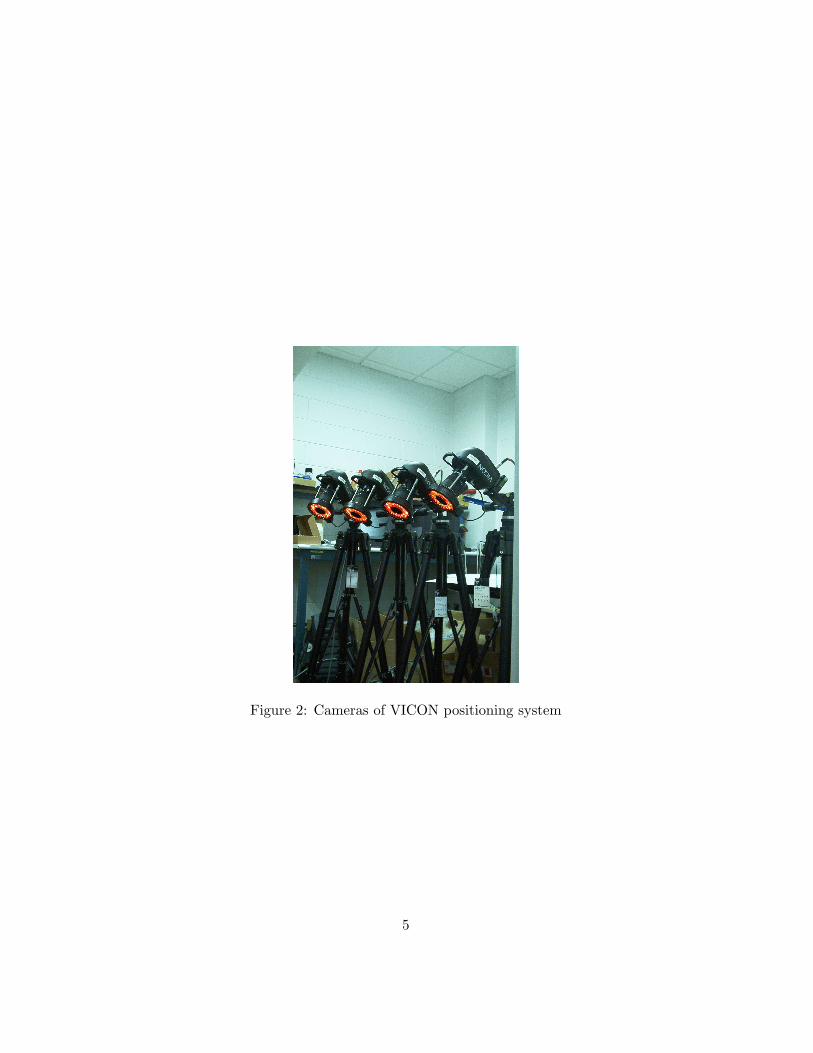
Figure 2: Cameras of VICON positioning system
5

1.3 Landing pad
The landing pad is shown in Fig. 3 and consists of a square, 1.2m × 1.2mpiece of plywood covered with Velcro. This piece of plywood may be easilytilted at various angles.
Figure 3: Landing pad
Complementary Velcro material is mounted under the helicopter land-ing skids, so that upon contact the two elements (the landing pad and thehelicopter landing gear) would effectively bond. While it may be arguedthat such a solution creates artificially favourable conditions for successfullandings, we consider that it constitutes a useful intermediate step towardperforming landings in unequipped areas at unusual attitudes. In addition,with the development of Velcro-like material made out of shape-memory al-loys [Eur], this option may even prove viable in several operational instances.
Experimental layout
Flight tests were conducted in the courtyard of Georgia Tech’s School ofAerospace, a closed area used primarily as temporary parking space. A topview of the camera layout is given in Fig. 4. The VICON cameras werelocated in such a way that accurate position, velocity, attitude and angularvelocity information could be obtained for the helicopter in a corridor con-taining the helicopter initial position and the landing area. This corridoris 6 meters deep, 1 meter wide at maneuver inception and greater than 3meters wide near the landing area. The available corridor height is about 3
6

meters.
Figure 4: Camera Layout
2 Experiments with humans in the loop
The first set of experiments involved an expert human pilot aiming at landingthe helicopter on a moderately pitched target (25 degrees). The humanpilot was chosen for his ability to perform advanced aerobatic maneuvers(including inverted flight, loops, flips, rolls etc.). The flight was performedat night, which challenged the pilot’s ability to precisely locate the helicopterrelative to the target. In particular, the strategy followed by the pilot toland the helicopter failed to exhibit many of the desired characteristics forlanding at high pitch angles: The precise navigation requirements associatedwith helicopter landing forced the pilot to give up on adjusting the helicopter
7
pitch angle so as to match that of the landing pad. Instead, the pilot chose tohover the helicopter horizontally above the landing pad, and then droppedthe helicopter on the pad by bringing the collective control down. Thisexperiment showed that previously developed human-inspired strategies foraggressive flight control [GMF+01, GMF04, ACQN07, NCD+04] could notbe applied to the task described in this paper.
One of the benefits of the piloted experiments, however, was to demon-strate the validity of the “Velcro” landing pad concept, since the helicoptersuccessfully and systematically bonded with the landing pad.
3 Landing maneuver design
This section presents our landing maneuver design philosophy, followed bya detailed presentation of the control laws used to perform the maneuver.
3.1 Overall philosophy
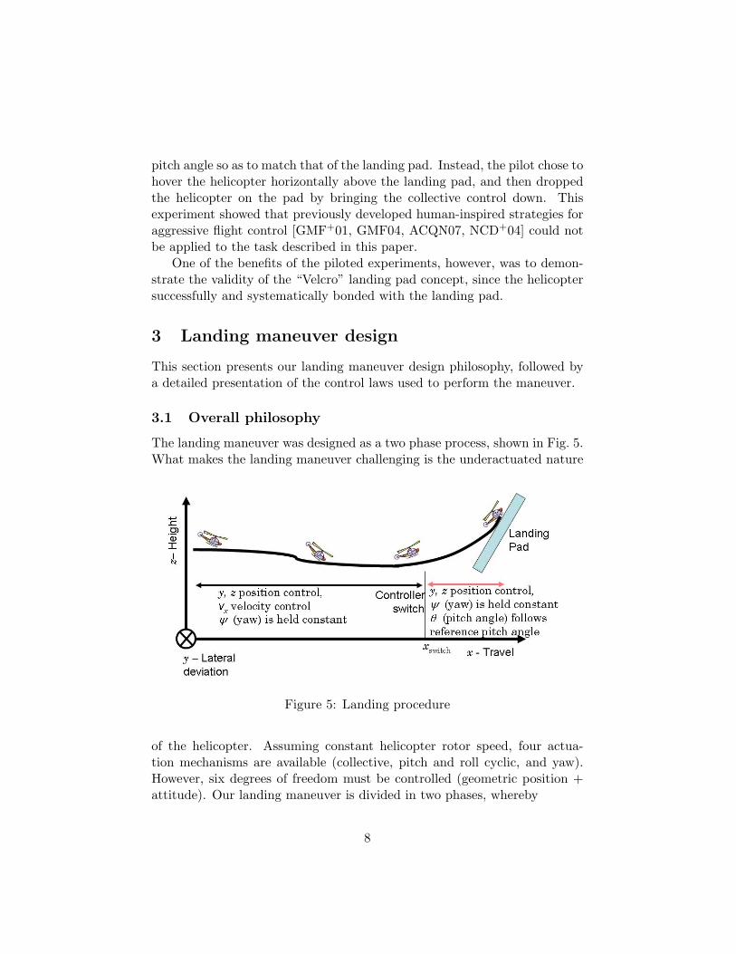
The landing maneuver was designed as a two phase process, shown in Fig. 5.What makes the landing maneuver challenging is the underactuated nature
Figure 5: Landing procedure
of the helicopter. Assuming constant helicopter rotor speed, four actua-tion mechanisms are available (collective, pitch and roll cyclic, and yaw).However, six degrees of freedom must be controlled (geometric position +attitude). Our landing maneuver is divided in two phases, whereby
8

• During approach, the lateral position y, altitude z, forward velocity xand yaw angle ψ of the helicopter are primarily controlled.
• During flare and eventual landing, the pitch (θ) and yaw (ψ) anglesof the helicopter are primarily controlled, together with the helicopterlateral position y and altitude z.
Thus, the vehicle undergoes a controller mode switch during the maneu-ver so as to enable the landing maneuver. This mode switch is reminiscentof strategies previously used in previous demonstrations of aerobatic flightby miniature helicopters [GMF+01, GMF03]. The mode switch is triggeredwhen the longitudinal vehicle position x crosses a specific threshold xswitch.
3.2 Fail safe landing procedure
Owing to sensing limitations and the inherent risks associated with landingat high pitch angle, a fail-safe landing sequence was designed so that thevehicle could recover in case of a missed landing: Following an approachsimilar to that used in fixed-wing Naval operations, an abort maneuver wasprogrammed to be executed whether the landing actually occurs or not.This procedure was based on the observation that once the velcro pads onthe landing pad and on the helicopter are in contact, they provide such astrong bond that any follow-on control sequence from the abort procedureapplied to the helicopter is ineffective at inducing any significant helicoptermotion. On the other hand, should the helicopter fail to get in contact withthe landing pad, the abort procedure can fully recover the helicopter andprevent a crash: Indeed, at high pitch angles, missed contact with the targetmeans that the helicopter immediately enters a glide motion down towardsthe ground, that must be handled immediately. In that regard, the proce-dure is similar to some fixed-wing aircraft naval aircraft operations, wherebylandings are followed by the beginning of an aborted landing procedure incase the aircraft tail hook fails to catch one of the transverse cables.
3.3 Control architecture
The control architecture is given by the diagram in Fig 6. Depending onthe phase of the flight, only part or all of the controller architecture is used:For example, when hover control is desired, the entire control architectureis used. However, the vehicle forward velocity vx may be controlled directlyas well. Likewise, the helicopter pitch angle can be controlled directly.
9
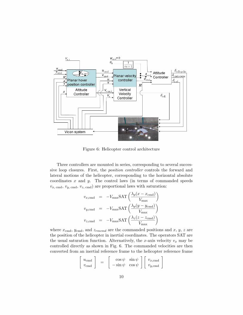
Figure 6: Helicopter control architecture
Three controllers are mounted in series, corresponding to several succes-sive loop closures. First, the position controller controls the forward andlateral motions of the helicopter, corresponding to the horizontal absolutecoordinates x and y. The control laws (in terms of commanded speedsvx, cmd, vy, cmd, vz, cmd) are proportional laws with saturation:
vx,cmd = −VmaxSAT(λp(x− xcmd)
Vmax
)vy,cmd = −VmaxSAT
(λp(y − ycmd)
Vmax
)vz,cmd = −VmaxSAT
(λz(z − zcmd)
Vmax
)where xcmd, ycmd, and zrmcmd are the commanded positions and x, y, z arethe position of the helicopter in inertial coordinates. The operators SAT arethe usual saturation function. Alternatively, the x-axis velocity vx may becontrolled directly as shown in Fig. 6. The commanded velocities are thenconverted from an inertial reference frame to the helicopter reference frame[
ucmd
vcmd
]=
[cosψ sinψ− sinψ cosψ
] [vx,cmd
vy,cmd
]
10

In these expressions, λp and λz are appropriately chosen positive constants.The planar velocity command loop is computed as follows. A second-
order velocity response is sought, such that
d
dtu = λu(ucmd − u+ iu)
d
dtv = λv(vcmd − v + iv)
d
dtiu = kiu(ucmd − u)
d
dtiv = kiv(vcmd − v).
(1)
The presence of integrators (with states iu and iv) aims at guaranteeingzero tracking error. In these expressions, λu, λv, kiu and kiv are appropri-ately chosen positive constants. Assuming the simplified helicopter planardynamics
d
dtu = 1
m(−Tcolθcmd + kdu |u|u)
d
dtv = 1
m(Tcolφcmd + kdv |v| v),(2)
where the mass of the helicopter m and the aerodynamic constants kdu
and kdv are determined experimentally, and inverting the dynamics leads toexpressions for θcmd and φcmd
θcmd = − 1Tcol
(λum(iu + ucmd − u)− kduu |u|)φcmd = 1
Tcol(λvm(iv + vcmd − v)− kdvv |v|)
by combining (1) and (2) together. Alternatively, the pitch angle θ may bedirectly commanded via the input θd. To avoid high-frequency excitationof the helicopter pitch cyclic, θd is subject to low-pass (first-order) filtering.Together with the desired heading ψcmd, the Euler angles θcmd and φcmd
allow us to form the desired attitude, expressed by the rotation matrixRcmd (the reader is invited to consult standard textbooks [Nel98] for theexpression of the rotation matrix Rcmd as a function of φcmd, θcmd, andψcmd). Computing the rotation error mnatrix Rerr = RTcmdR and computingεerr = logRerr (here the log operation applies to matrices as the inverse ofthe matrix exponential), we obtain
εerr =
0 −εz εyεz 0 −εx−εy εx 0
.11
Standard results about rotations indicate that the orientation error Rerr
is a rotation whose axis is [εx εy εz]T and whose angular amplitude is√ε2x + ε2y + ε2z. The proportional control law
δrollcyclic = kφεxδpitchcyclic = kθεy
δrud = kψεz
was chosen for its simplicity and ability to steer R towards Rcmd. Dampingis provided by the helicopter dynamics, including the Hillier stabilizer barsand the built-in gyroscopic yaw damper.
The velocity controller about the z inertial axis was computed using thedesired behavior
d
dtvz = λvz(vz,cmd − vz + ivz)
d
dtivz = kivz
(vz,cmd − vz).
Using the simplified vertical dynamics
vz =1m
(−Tcoll cos θ cosφ+mg − kzvz),
andTcoll = kcollδcoll
yields the desired control law
δcoll =gm− λvzm(ivz + vz − vz,cmd)− kzvz
kcoll cos θ cosφ.
Such a control architecture enables a high-level, discrete control of the he-licopter: The landing sequence may be seen as a discrete sequence of stepinputs to the control architecture as shown in Fig. 7.
Experimental results
The controlled helicopter was able to perform several landings, eventuallyreaching 60 degrees pitch angle at landing. Initial landings were performedat much smaller pitch angles (eg 10 degrees) for the purpose of calibratingthe landing procedure and the abort process, should it be needed. The pitch
12

Figure 7: Landing maneuver sequence
angle of the landing pad was then progressively increased so as to eventu-ally reach 60 degrees. Fig. 8 shows the trajectory followed by the helicopterduring one a successful landing. The corresponding time histories for atti-tude/attitude rates and position/speeds are given in Fig. 9 and Fig. 10. Itmust be noted that the landing maneuver is, so far, performed “open-loop”,that is the exact location of the landing pad was not measured in real-time,leading to several aborted maneuvers. Fig. 11 illustrates one such abortedmaneuver. Starting from a hovering position of at the location (2, 1) meters,the vehicle misses the target and executes an abort maneuver. The resultingmaneuver is fairly ample and the vehicle violates the boundaries of the flightcorridor.
4 Conclusion and further research
This note presented the first published landing of a small helicopter at highpitch angle, with landings on platforms with up to 60 degrees pitch. Suchmaneuvers, together with other aggressive maneuvers, contribute to form-ing the core knowledge that is necessary to enable bird-like behaviors forsmall unmanned air vehicles. Such behaviors include the ability for thesevehicles to alight at unusual attitudes. This interim result shows that these
13

2 3 4 5 6 7 8 90
1
2
3
2 3 4 5 6 7 8 9−1
−0.5
0
0.5
1
Figure 8: Successful landing: Top: Side view. Bottom: Top view. Heli-copter attitude is represented by blue segments. Consecutive segments areseparated by 0.06 sec.
14

0 0.5 1 1.5 2 2.5 3 3.5 4−200
−100
0
100
200
300
roll
(deg
) / p
(de
g/s)
X axis
0 0.5 1 1.5 2 2.5 3 3.5 4−100
0
100
200Y axis
pitc
h (d
eg)
/ q (
deg/
s)
0 0.5 1 1.5 2 2.5 3 3.5 4−50
0
50
100Z axis
Time (s)
yaw
(de
g) /
r (d
eg/s
)
Figure 9: Successful landing: Helicopter attitude/attitude rates.
15

Figure 10: Successful landing: Helicopter position/velocity. Top: Alongtrack position/velocity; Middle: Cross-track position/velocity. Bottom: Al-titude / vertical speed.
16

0 1 2 3 4 5 6 7 8 90
0.5
1
1.5
2
2.5
3
0 1 2 3 4 5 6 7 8 9−1
−0.8
−0.6
−0.4
−0.2
0
0.2
0.4
0.6
0.8
1
Figure 11: Aborted landing: Top: Side view. Bottom: Top view. Heli-copter attitude is represented by blue segments. Consecutive segments areseparated by 0.06 sec
17

high-agility behaviors are within reach of available vehicles and navigationsystems. Further research will include the “robustification” of the landingmaneuvers by effectively providing the vehicle with on-line feedback of itsposition relative to the target. It will also include reaching higher pitch an-gles, including partially inverted landings on overhanging landing sites andlandings on moving platforms. However, such activities will require a morecomprehensive positioning system since such maneuvers exceed our currentnavigation capabilities.
Acknowledgements
This research was supported by the Office of Naval Research under GrantN00014-06-1-1158. The authors would like to thank H. DeBlauwe, M. Gariel,T. Hunter, F. Lokumcu, V. Stojanovska, R. Valenzuela, and the safety pilotJ. Fine for their support during this effort.
References
[ACQN07] P. Abbeel, A. Coates, M. Quigley, and A.Y. Ng. An applicationof reinforcement learning to aerobatic helicopter flight. In Toappear in NIPS 19, 2007.
[Cor04] P. Corke. An inertial and visual sensing system for a smallautonomous helicopter. Journal of Robotic Systems, 21:43–51,2004.
[Eur] European Aeronautic Defence and Space Company.Intelligent metals - Future materials think ahead.http://www.eads.com/1024/en/pressdb/innovation topic/Archiv/Intelligente%20Metalle.html.
[GMF+01] V. Gavrilets, B. Mettler, E. Frazzoli, M. Piedmonte, andE. Feron. Aggressive maneuvering of small autonomous heli-copters: A human-centered approach. Int. J. Robotics Research,20(10):795–807, october 2001.
[GMF03] V. Gavrilets, B. Mettler, and E. Feron. Control logic for au-tomated aerobatic flight of a miniature helicopter. AIAA J.Guidance, Control and Dynamics, 2003.
18

[GMF04] V. Gavrilets, B. Mettler, and E. Feron. Human-inspired con-trol logic for automated maneuvering of a miniature helicopter.AIAA J. on Guidance, Control and Dynamics, 2004.
[GPSM02] P.J. Garcia-Pardo, G.S. Sukhatme, and James F. Montgomery.Towards vision-based safe landing for an autonomous helicopter.Robotics and Autonomous Systems, 38:19–29, 2002.
[IMS03] A. Isidori, L. Marconi, and A. Serrani. Robust nonlinear motioncontrol of a helicopter. IEEE Trans. Aut. Control, 48:413–426,2003.
[KS98] T.J. Koo and S. Sastry. Output tracking control design of ahelicopter model based on approximate linearization. In Proc.IEEE Conf. on Decision and Control, December 1998.
[NCD+04] A.Y. Ng, A. Coates, M. Diel, V. Ganapathi, J. Schulte, B. Tse,E. Berger, and E. Liang. Inverted autonomous helicopter flightvia reinforcement learning. In International Symposium on Ex-perimental Robotics, 2004.
[Nel98] R.C. Nelson. Flight Stability and Automatic Control. McGrawHill, 1998.
[OPA+05] S.-R. Oh, K. Pathak, S.K. Agrawal, H.R. Pota, and M. Garrett.Autonomous helicopter landing on a moving platform using atether. In IEEE International Conference on Robotics and Au-tomation, pages 3960–3965, April 2005.
[Roo07] P. Root. Personal communication. May 2007.
[SKHS98] H. Shim, T.J. Koo, F. Hoffmann, and S. Sastry. A comprehensivestudy of control design for an autonomous vehicle. In Preprint,volume 4, pages 3653–3658, 37th IEEE Conference on Decisionand Control, December 1998.
[SS03] S. Saripalli and G.S. Sukhatme. Landing on a moving targetusing an autonomous helicopter. In International Conference onField and Service Robotics, volume 2, Mt Fuji, Japan, july 2003.
[SSM03] S. Saripalli, G.S. Sukhatme, and J.F. Montgomery. An experi-mental study of the autonomous helicopter landing problem. InExperimental Robotics VIII, volume 5, pages 466–475, 2003.
19

[SSS01] C. Sharp, A. Shakernia, and S. Sastry. A vision system for land-ing unmnanned vehicles. In Proc. IEEE Int. Conf. Robotics andAutomation, Seoul, Korea, May 2001.
[SVS+02] O. Shakernia, R. Vidal, C. Sharp, Y. Ma, and S. Sastry. Multi-ple view motion estimation and control for landing an unmannedaerial vehicle. In Proc. IEEE Int. Conf. Robotics and Automa-tion, Washington, DC, May 2002.
[TSR+05] C. Theodore, S. Sheldon, D. Rowley, T. McLain, W. Dai,and M. Takahashi. Full mission simulation of a rotorcraft un-manned aerial vehicle for landing in a non-cooperative environ-ment. In 61st Annual Forum of the American Helicopter Society,Grapevine, TX, June 2005.
[TVHF06] G. Tournier, M. Valenti, J. How, and E. Feron. Estimation andcontrol of a quadrotor vehicle using monocular vision and moirpatterns. In AIAA Guidance, Navigation and Control Confer-ence, pages 2006–6711, Keystone, Colo., august 2006. AIAA.
[VBF+06] M. Valenti, B. Bethke, G. Fiore, J. How, and E. Feron. Indoormulti-vehicle flight testbed for fault isolation, detection and re-covery. In AIAA Guidance, Navigation, and Control Conferenceand Exhibit, number AIAA paper 2006-6200, pages 98–108, Key-stone, CO, August 2006.
[Wil07] J.R. Wilson. UAV worldwide roundup 2007. Aerospace America,(5):30–37, May 2007.
20