Embed Size (px)
Citation preview
VOL. 11, NO. 24, DECEMBER 2016 ISSN 1819-6608
ARPN Journal of Engineering and Applied Sciences
©2006-2016 Asian Research Publishing Network (ARPN). All rights reserved.
www.arpnjournals.com
14383
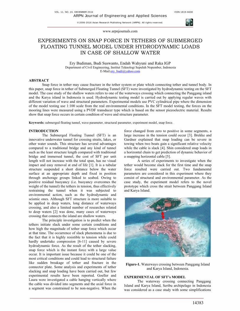
EXPERIMENTS ON SNAP FORCE IN TETHERS OF SUBMERGED FLOATING TUNNEL MODEL UNDER HYDRODYNAMIC LOADS
IN CASE OF SHALLOW WATER
Ery Budiman, Budi Suswanto, Endah Wahyuni and Raka IGP Department of Civil Engineering, Institut Teknologi Sepuluh Nopember, Indonesia
E-Mail:[email protected]
ABSTRACT
Snap force in tether may cause fracture in the tether system or plate which connecting tether and tunnel body. In this paper, snap force in tether of Submerged Floating Tunnel (SFT) were investigated by hydrodynamic testing on the SFT model. The case study of the shallow waters refers to one of the waterways crossing which connecting the Panggang island and the Karya island in Indonesia is used. Hydrodynamic testing model is carried out by applying regular waves with different variation of wave and structural parameters. Experimental models use PVC cylindrical pipe where the dimension of the model testing use 1:100 scale from the real environmental conditions. In the SFT model testing, the forces on the mooring lines were measured using a PVDF transducer type which is based on the sensor piezoelectric material. Results show that snap force occurs in certain condition of wave and structure parameter. Keywords: submerged floating tunnel, wave parameter, structural parameter, experiment model, snap force. INTRODUCTION
The Submerged Floating Tunnel (SFT) is an innovative underwater tunnel for crossing straits, lakes, or other water sounds. This structure has several advantages compared to a traditional bridge and any kind of tunnel such as the least structure length compared with traditional bridge and immersed tunnel, the cost of SFT per unit length will not increase with the total span, has no visual impact and easy removal at end of life [1]. It is a tubular structure suspended a short distance below the water surface at an appropriate depth and fixed in position through anchorage groups linked to seabed. Owing to positive residual buoyancy (i.e. buoyancy overcomes the weight of the tunnel) the tethers in tension, thus effectively restraining the tunnel when it was subjected to environmental action, such as the hydrodynamic and seismic ones. Although SFT structure is more suitable to be applied in deep waters, long distance of waterways crossing, and also a limited number of researches related to deep waters [2] was done, many cases of waterways crossing that connects the island are shallow waters.
The principle investigation is to predict when the tethers initiate slack under some certain conditions and how high the magnitude of tether snap force which occur at that time. The occurrence of slack phenomena is due to the fact that it is highly resistible to tension while could hardly undertake compression [6-11] caused by severe hydrodynamic force. As the result of the tether slacking, snap force which is the instant force with a large value occur. It is important issue because it could be one of the most critical conditions and could lead to structural failure like sudden breakage of tether and fracture in the connector plate. Some analysis and experiments of tether slacking and snap loading have been carried out, but few experimental results have been reported. Goeller and Laura were investigated a cable hanging vertically where the cable was divided into segments and the axial force in a segment was constrained to be non-negative. When the
force changed from zero to positive in some segments, a large increase in the tension could occur [3]. Brekke and Gardner explained that snap loading can be severe in towing when two boats gain a significant relative velocity while the cable is slack [4]. Shin considered snap loads in a horizontal chain to get prediction of dynamic behavior of a snapping horizontal cable [5].
A series of experiments to investigate when the tether would become slack for the first time and the snap force resulted were carried out. Two fundamental parameters are considered in this experiment where they consist of structural and environmental parameter. As the case study, the experiment model refers to the novel prototype which cross the strait between Panggang Island and Karya Island.
Figure-1. Waterways crossing between Panggang Island and Karya Island, Indonesia.
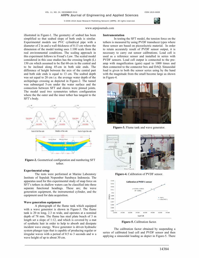
EXPERIMENTAL OF SFT’s MODEL
The waterway crossing connecting Panggang Island and Karya Island, Seribu archipelago in Indonesia was considered as a case study with some simplifications
VOL. 11, NO. 24, DECEMBER 2016 ISSN 1819-6608
ARPN Journal of Engineering and Applied Sciences
©2006-2016 Asian Research Publishing Network (ARPN). All rights reserved.
www.arpnjournals.com
14384
illustrated in Figure-1. The geometry of seabed has been simplified so that seabed slope of both ends is similar. Experimental models use PVC cylindrical pipe with a diameter of 2 in and a wall thickness of 0.13 cm where the dimension of the model testing uses 1:100 scale from the real environmental conditions. The scaling approach in this experiment follows to Froud’s Law. The scaled model considered in this case studies has the crossing length (L) 150 cm which assumed to be flat 60-cm in the central and to be inclined along 45-cm in both side ends. The difference of height between the axis of the central part and both side ends is equal to 13 cm. The seabed depth was set equal to 20 cm i.e. the average water depth of the archipelago crossing as depicted in Figure-2. The tunnel was submerged 5-cm under the water surface and the connection between SFT and shores were pinned joints. The model used two symmetries tethers configuration where the the outer and the inner tether has tangent to the SFT’s body.
Figure-2. Geometrical configuration and numbering SFT tether.
Experimental setup
The tests were performed at Marine Laboratory Institute of Sepuluh Nopember Surabaya Indonesia. The apparatus used for this experimental study of snap force on SFT’s tethers in shallow waters can be classified into three separate functional headings. These are; the wave generation equipment, the instrumented cylinder, and the equipment used for data acquisition. Wave generation equipment
A photograph of the flume tank which equipped with a wave generator is shown in Figure-3. The flume tank is 20 m long, 2.3 m wide, and operates at a nominal depth of 78 mm. The flume has steel plate beach of 3 m length set a slope of 1:12, and which is covered by a mat of synthetic hair in order to help to absorb and dissipate incident wave energy. Wave generator is driven hydraulic system plunger type that is capable of producing regular or irregular waves with a period of 0.5 to 3 seconds and w a wave height of up to about 30 cm.
Instrumentation In testing the SFT model, the tension force on the
tethers is measured by using PVDF transducer types where these sensor are based on piezoelectric material. In order to retain accurately result of PVDF sensor output, it is necessary to carry out sensor calibrations. Load cell is used as a reference sensor and installed in series with PVDF sensors. Load cell output is connected to the pre-amp with magnification (gain) equal to 1000 times and then connected to the connector box and DAQ. Sinusoidal load is given to both the sensor series using by the hand with the magnitude from the small become large as shown in Figure-4.
Figure-3. Flume tank and wave generator.
Figure-4. Calibration of PVDF sensor.
Figure-5. Calibration factor. The calibration factor obtained by suspending a
series of calibrated load cell and PVDF sensor and then applying a sinusoidal loading as depict in Figure-5. There
VOL. 11, NO. 24, DECEMBER 2016 ISSN 1819-6608
ARPN Journal of Engineering and Applied Sciences
©2006-2016 Asian Research Publishing Network (ARPN). All rights reserved.
www.arpnjournals.com
14385
are eight transducers-PVDF type installed on SFT model as shown in Figure-6.
Figure-6. Installing of PVDF sensor.
Data acquisition equipment In addition to physical factor which effect the
magnitude of the tension force on tethers, the accuracy with which this highly dynamic force measured and stored depend on the instrument. After the force is converted to a voltage, the signal is amplified, digitized, and stored as numerical data for further analysis. The accuracy of sampled data corresponding to the force depend on linearity of transducer and amplifiers and their ability to remain drift free between calibration and actual test. Data acquisition (DAQ) is the process of measuring an electrical phenomenon such as voltage with a computer. A DAQ system consists of sensors, DAQ measurement hardware, and a computer with programmable software. Figure-7 shows a flow chart of the apparatus used for acquiring force data during experiment.
Figure-7. Flow chart of data acquisition.
Testing Testing of SFT can be categorized into two types:
static testing and dynamic testing. Static testing aims to design the amount of ballast used in Buoyancy Weight Ratio (BWR) testing type so this testing only involves hydrostatic force and gravity of the structure. The test model is placed in a water bath that is immersed in water with a depth of 5 cm where each of the two ends mounted load cell to measure the reaction of force resultant. Load
cell measurement results represent the difference between buoyant force and the own weight. With knowing buoyant force acting on the body model at specific depths we can design a ballast weight for each value of BWR.
Figure-8. Photograp of model assembly and testing model.
Dynamic testing involves own weight of
structure, buoyant force and wave force. Wave force applied to the test model is regular wave. In this testing there are two parameters to be investigated. These are the wave parameters and structural parameters. Wave parameters investigated consists of wave height and wave period. Structural fundamental parameter investigated consist of Buoyancy Weight Ratio (BWR), Inclined Tether Angle (ITA), tether diameter and end side restraint. The SFT model is moored by tethers into simplified seabed model related to case study. The both ends are restrained into supporting frame as shown in Figure-8. The tethers were connected by PVDF sensor. The Signal generated by PVDF sensor is amplified, digitized and store in DAQ equipment and finally displayed by computer program. RESULTS AND DISCUSSION Effect of wave parameters
The reguler wave is generated in this SFT experiment testing. A series of wave height (1,3,5,7,9 and 11 cm) and wave period (4,6,8,10,12, and 14s) were applied in SFT model. The wave parameter data input used in this research refers to the investigation results of the Java Sea wave by Indonesian Hydrodynamic Laboratory- BPPT as shown in Table-1. According to that investigation, in the 100th year return period, maximum the individual wave height is about 9 m and maximum the individual wave period is about 12 seconds. Both of those wave parameter are used as a reference value in variation of testing parameter .
Effect of wave height
Time series of SFT tether tension subjected to waves with different heights, in which T1 and T2 are tether tensions of No.1 and No.2 respectively, i.e. the outer tether and inner tether. The magnitude of the wave force is a function of water depth where the greater water depth, the lesser the influence of the wave force.
VOL. 11, NO. 24, DECEMBER 2016 ISSN 1819-6608
ARPN Journal of Engineering and Applied Sciences
©2006-2016 Asian Research Publishing Network (ARPN). All rights reserved.
www.arpnjournals.com
14386
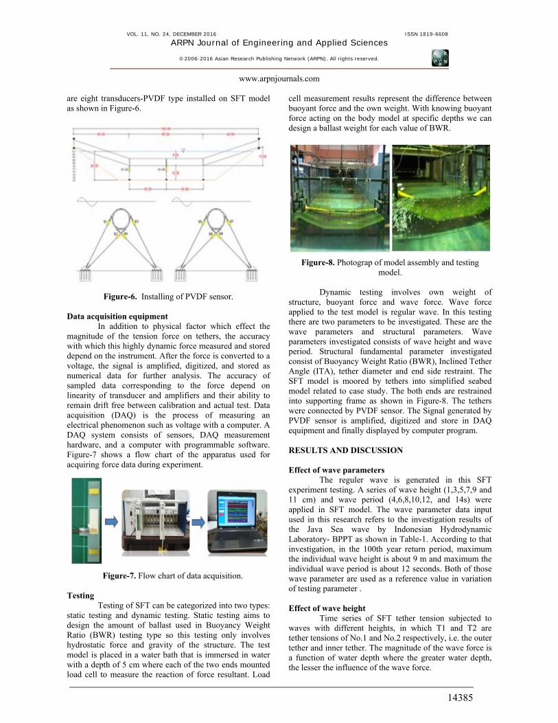
Table-1. Return period of maximum wave height in the northern Gulf of Jakarta, Java Sea (IHL-BPPT, 2011).
(a)
(b)
(c)
Figure-9. Time series of tension tether a) T=12s H=7cm b)T=12s, H=9cm; c) T=12s H=11cm.
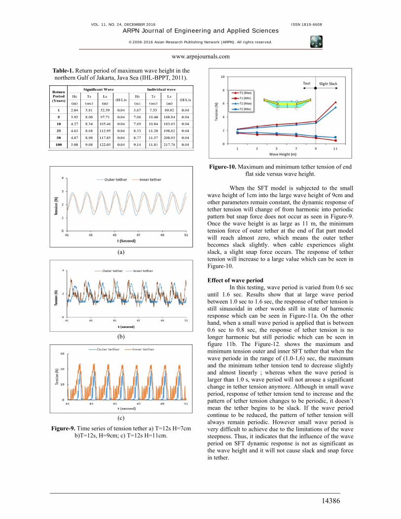
Figure-10. Maximum and minimum tether tension of end flat side versus wave height.
When the SFT model is subjected to the small
wave height of 1cm into the large wave height of 9cm and other parameters remain constant, the dynamic response of tether tension will change of from harmonic into periodic pattern but snap force does not occur as seen in Figure-9. Once the wave height is as large as 11 m, the minimum tension force of outer tether at the end of flat part model will reach almost zero, which means the outer tether becomes slack slightly. when cable experiences slight slack, a slight snap force occurs. The response of tether tension will increase to a large value which can be seen in Figure-10. Effect of wave period
In this testing, wave period is varied from 0.6 sec until 1.6 sec. Results show that at large wave period between 1.0 sec to 1.6 sec, the response of tether tension is still sinusoidal in other words still in state of harmonic response which can be seen in Figure-11a. On the other hand, when a small wave period is applied that is between 0.6 sec to 0.8 sec, the response of tether tension is no longer harmonic but still periodic which can be seen in figure 11b. The Figure-12. shows the maximum and minimum tension outer and inner SFT tether that when the wave periode in the range of (1.0-1,6) sec, the maximum and the minimum tether tension tend to decrease slightly and almost linearly ; whereas when the wave period is larger than 1.0 s, wave period will not arouse a significant change in tether tension anymore. Although in small wave period, response of tether tension tend to increase and the pattern of tether tension changes to be periodic, it doesn’t mean the tether begins to be slack. If the wave period continue to be reduced, the pattern of tether tension will always remain periodic. However small wave period is very difficult to achieve due to the limitations of the wave steepness. Thus, it indicates that the influence of the wave period on SFT dynamic response is not as significant as the wave height and it will not cause slack and snap force in tether.
VOL. 11, NO. 24, DECEMBER 2016 ISSN 1819-6608
ARPN Journal of Engineering and Applied Sciences
©2006-2016 Asian Research Publishing Network (ARPN). All rights reserved.
www.arpnjournals.com
14387
(a)
(b)
Figure-11.Time series of tension tether (a) H=7cm,Ts=1.2s; (b)H=7cm, Ts=0.6.
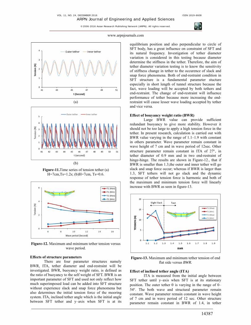
Figure-12. Maximum and minimum tether tension versus wave period.
Effects of structure parameters
There are four parameter structures namely BWR, ITA, tether diameter and end-restraint will be investigated. BWR, buoyancy weight ratio, is defined as the ratio of buoyancy to the self weight of SFT. BWR is an important parameter of SFT and used not only reflect how much superimposed load can be added into SFT structure without experience slack and snap force phenomena but also determines the initial tension force of the mooring system. ITA, inclined tether angle which is the initial angle between SFT tether and y–axis when SFT is at its
equilibrium position and also perpendicular to circle of SFT body, has a great influence on constraint of SFT and its natural frequency. Investigation of tether diameter variation is considered in this testing because diameter determine the stiffness in the tether. Therefore, the aim of tether diameter variation testing is to know the sensitivity of stiffness change in tether to the occurence of slack and snap force phenomena. Both of end-restraint condition in SFT structure is a fundamental parameter stucture especially in short length of tunnel structure because the fact, wave loading will be accepted by both tethers and end-restraint. The change of end-restraint will influence performance of tether because more increasing the end-restraint will cause lesser wave loading accepted by tether and vice versa.
Effect of bouyancy weight ratio (BWR)
Large BWR value can provide sufficient redundant buoyancy to give more stability. However it should not be too large to apply a high tension force in the tether. In present research, calculation is carried out with BWR value varying in the range of 1.1–1.9 with constant in others parameter. Wave parameter remain constant in wave height of 7 cm and in wave period of 12sec. Other structure parameter remain constant in ITA of 27, in tether diameter of 0.9 mm and in two end-restraint of hinge-hinge. The results are shown in Figure-12., that if BWR is smaller than 1.3,the outer and inner tether will go slack and snap force occur; whereas if BWR is larger than 1.3, SFT tethers will not go slack and the dynamic response of tether tension force is harmonic and both of the maximum and minimum tension force will linearly increase with BWR as seen in figure-13.
Figure-13. Maximum and minimum tether tension of end flat side versus BWR.
Effect of inclined tether angle (ITA)
ITA is measured from the initial angle between SFT tether until y–axis when SFT is at its stationary position. The outer tether is varying in the range of 0–54. The both wave and structural parameter remain constant. Wave parameter remain constant in wave height of 7 cm and in wave period of 12 sec. Other structure parameter remain constant in BWR of 1.4, in tether
VOL. 11, NO. 24, DECEMBER 2016 ISSN 1819-6608
ARPN Journal of Engineering and Applied Sciences
©2006-2016 Asian Research Publishing Network (ARPN). All rights reserved.
www.arpnjournals.com
14388
diameter of 0.9 mm and in two SFT end-restraint of hinge-hinge condition. When the ITA reachs 180, the dynamic response of tether appears periodic but slack and snap force does not occur, the snap force begins to occur. Figure-14 shows the relation of the maximum and minimum tether tension force and from which it is seen when ITA is larger than zero slack will occur, but if the angle reaches 18 the tethers remain taut again and the dynamic response of tether tension force is harmonic with both of the maximum and minimum tension force will decrease with the increasing of ITA.
Figure-14. Maximum and minimum tether tension of end flat side versus ITA.
Effect of tether diameter
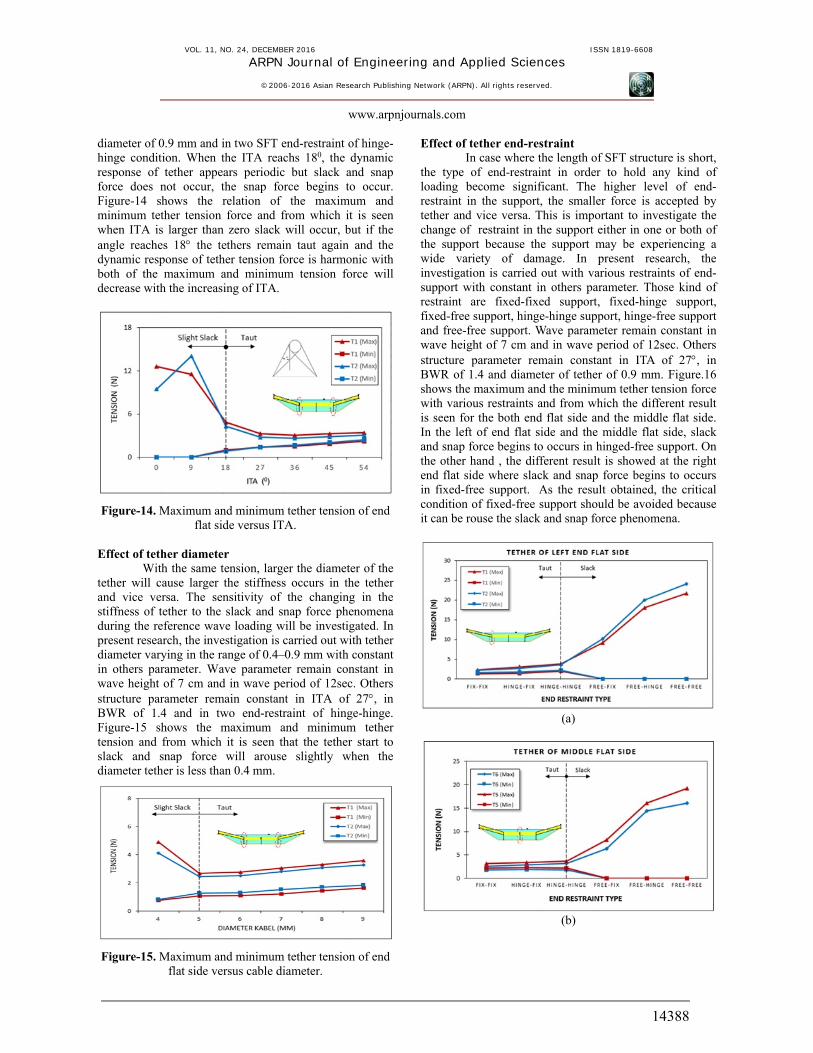
With the same tension, larger the diameter of the tether will cause larger the stiffness occurs in the tether and vice versa. The sensitivity of the changing in the stiffness of tether to the slack and snap force phenomena during the reference wave loading will be investigated. In present research, the investigation is carried out with tether diameter varying in the range of 0.4–0.9 mm with constant in others parameter. Wave parameter remain constant in wave height of 7 cm and in wave period of 12sec. Others structure parameter remain constant in ITA of 27, in BWR of 1.4 and in two end-restraint of hinge-hinge. Figure-15 shows the maximum and minimum tether tension and from which it is seen that the tether start to slack and snap force will arouse slightly when the diameter tether is less than 0.4 mm.
Figure-15. Maximum and minimum tether tension of end flat side versus cable diameter.
Effect of tether end-restraint In case where the length of SFT structure is short,
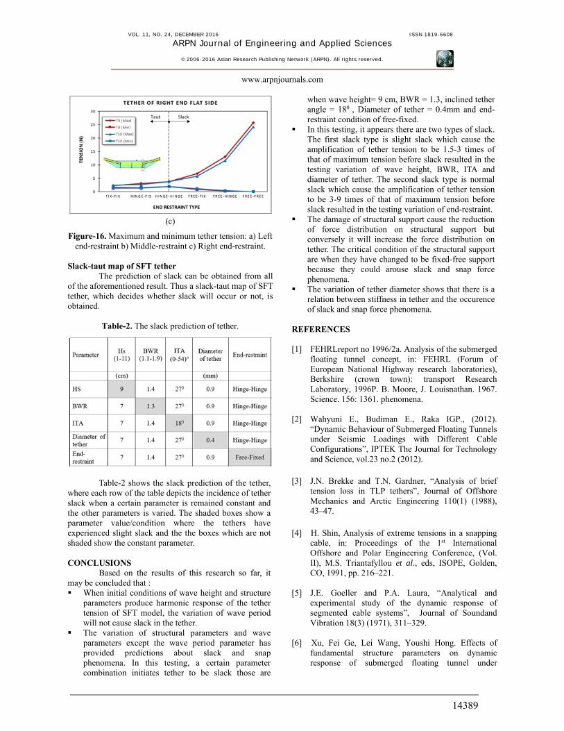
the type of end-restraint in order to hold any kind of loading become significant. The higher level of end-restraint in the support, the smaller force is accepted by tether and vice versa. This is important to investigate the change of restraint in the support either in one or both of the support because the support may be experiencing a wide variety of damage. In present research, the investigation is carried out with various restraints of end-support with constant in others parameter. Those kind of restraint are fixed-fixed support, fixed-hinge support, fixed-free support, hinge-hinge support, hinge-free support and free-free support. Wave parameter remain constant in wave height of 7 cm and in wave period of 12sec. Others structure parameter remain constant in ITA of 27, in BWR of 1.4 and diameter of tether of 0.9 mm. Figure.16 shows the maximum and the minimum tether tension force with various restraints and from which the different result is seen for the both end flat side and the middle flat side. In the left of end flat side and the middle flat side, slack and snap force begins to occurs in hinged-free support. On the other hand , the different result is showed at the right end flat side where slack and snap force begins to occurs in fixed-free support. As the result obtained, the critical condition of fixed-free support should be avoided because it can be rouse the slack and snap force phenomena.
(a)
(b)
VOL. 11, NO. 24, DECEMBER 2016 ISSN 1819-6608
ARPN Journal of Engineering and Applied Sciences
©2006-2016 Asian Research Publishing Network (ARPN). All rights reserved.
www.arpnjournals.com
14389
(c)
Figure-16. Maximum and minimum tether tension: a) Left end-restraint b) Middle-restraint c) Right end-restraint.
Slack-taut map of SFT tether
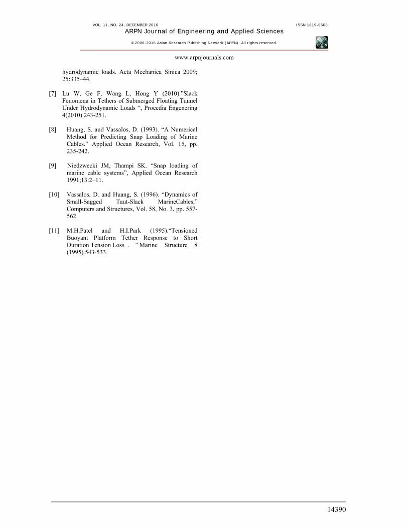
The prediction of slack can be obtained from all of the aforementioned result. Thus a slack-taut map of SFT tether, which decides whether slack will occur or not, is obtained.
Table-2. The slack prediction of tether.
Table-2 shows the slack prediction of the tether, where each row of the table depicts the incidence of tether slack when a certain parameter is remained constant and the other parameters is varied. The shaded boxes show a parameter value/condition where the tethers have experienced slight slack and the the boxes which are not shaded show the constant parameter. CONCLUSIONS
Based on the results of this research so far, it may be concluded that : When initial conditions of wave height and structure
parameters produce harmonic response of the tether tension of SFT model, the variation of wave period will not cause slack in the tether.
The variation of structural parameters and wave parameters except the wave period parameter has provided predictions about slack and snap phenomena. In this testing, a certain parameter combination initiates tether to be slack those are
when wave height= 9 cm, BWR = 1.3, inclined tether angle = 180 , Diameter of tether = 0.4mm and end-restraint condition of free-fixed.
In this testing, it appears there are two types of slack. The first slack type is slight slack which cause the amplification of tether tension to be 1.5-3 times of that of maximum tension before slack resulted in the testing variation of wave height, BWR, ITA and diameter of tether. The second slack type is normal slack which cause the amplification of tether tension to be 3-9 times of that of maximum tension before slack resulted in the testing variation of end-restraint.
The damage of structural support cause the reduction of force distribution on structural support but conversely it will increase the force distribution on tether. The critical condition of the structural support are when they have changed to be fixed-free support because they could arouse slack and snap force phenomena.
The variation of tether diameter shows that there is a relation between stiffness in tether and the occurence of slack and snap force phenomena.
REFERENCES [1] FEHRLreport no 1996/2a. Analysis of the submerged
floating tunnel concept, in: FEHRL (Forum of European National Highway research laboratories), Berkshire (crown town): transport Research Laboratory, 1996P. B. Moore, J. Louisnathan. 1967. Science. 156: 1361. phenomena.
[2] Wahyuni E., Budiman E., Raka IGP., (2012).
“Dynamic Behaviour of Submerged Floating Tunnels under Seismic Loadings with Different Cable Configurations”, IPTEK The Journal for Technology and Science, vol.23 no.2 (2012).
[3] J.N. Brekke and T.N. Gardner, “Analysis of brief
tension loss in TLP tethers”, Journal of Offshore Mechanics and Arctic Engineering 110(1) (1988), 43–47.
[4] H. Shin, Analysis of extreme tensions in a snapping
cable, in: Proceedings of the 1st International Offshore and Polar Engineering Conference, (Vol. II), M.S. Triantafyllou et al., eds, ISOPE, Golden, CO, 1991, pp. 216–221.
[5] J.E. Goeller and P.A. Laura, “Analytical and
experimental study of the dynamic response of segmented cable systems”, Journal of Soundand Vibration 18(3) (1971), 311–329.
[6] Xu, Fei Ge, Lei Wang, Youshi Hong. Effects of
fundamental structure parameters on dynamic response of submerged floating tunnel under
VOL. 11, NO. 24, DECEMBER 2016 ISSN 1819-6608
ARPN Journal of Engineering and Applied Sciences
©2006-2016 Asian Research Publishing Network (ARPN). All rights reserved.
www.arpnjournals.com
14390
hydrodynamic loads. Acta Mechanica Sinica 2009; 25:335–44.
[7] Lu W, Ge F, Wang L, Hong Y (2010).”Slack
Fenomena in Tethers of Submerged Floating Tunnel Under Hydrodynamic Loads “, Procedia Engenering 4(2010) 243-251.
[8] Huang, S. and Vassalos, D. (1993). “A Numerical
Method for Predicting Snap Loading of Marine Cables.” Applied Ocean Research, Vol. 15, pp. 235-242.
[9] Niedzwecki JM, Thampi SK. “Snap loading of
marine cable systems”, Applied Ocean Research 1991;13:2–11.
[10] Vassalos, D. and Huang, S. (1996). “Dynamics of
Small-Sagged Taut-Slack MarineCables,” Computers and Structures, Vol. 58, No. 3, pp. 557-562.
[11] M.H.Patel and H.I.Park (1995).“Tensioned
Buoyant Platform Tether Response to Short Duration Tension Loss . ” Marine Structure 8 (1995) 543-533.