Embed Size (px)
Citation preview

JOURNAL OF THEORETICAL
AND APPLIED MECHANICS
55, 4, pp. 1219-1233, Warsaw 2017DOI: 10.15632/jtam-pl.55.4.1219
EXPERIMENTAL AND NUMERICAL ANALYSIS OF ALUMINUM ALLOYAW5005 BEHAVIOR SUBJECTED TO TENSION AND PERFORATION
UNDER DYNAMIC LOADING
Amine Bendarma
Poznan University of Technology, Institute of Structural Engineering, Poznań, Poland, and
Universiapolis, Ecole Polytechnique d’Agadir Bab Al Madina, Qr Tilila, Agadir, Morocco
e-mail: [email protected]
Tomasz Jankowiak, Tomasz Łodygowski
Poznan University of Technology, Institute of Structural Engineering, Poznań, Poland
e-mail: [email protected]; [email protected]
Alexis Rusinek
Laboratory of Mechanics, Biomechanics, Polymers and Structures (LaBPS),
National Engineering School of Metz (ENIM), Metz, France; e-mail: [email protected]
Maciej Klósak
Universiapolis, Ecole Polytechnique d’Agadir Bab Al Madina, Qr Tilila, Agadir, Morocco, and
The International University of Logistics and Transport in Wrocław, Poland
e-mail: [email protected]
The paper describes mechanical behavior of aluminum alloy AW5005 (EN AW5005) un-der impact loading. The work is focused on tensile tests and the process of perforation ofaluminum alloy AW5005 sheets. Experimental, analytical and numerical investigations arecarried out to analyse in details the perforation process. Based on these approaches, ballisticproperties of the structure impacted by a conical nose shape projectile are studied. Differentfailure criteria are discussed, coupling numerical and experimental analyses for a wide rangeof strain rates. Optimization method functions are used to identify the parameters of thefailure criteria. Finally, good correlation is obtained between the numerical and experimentalresults for both tension and perforation tests.
Keywords: aluminum alloy, AW5005, ballistic behavior, failure criterion
1. Introduction
In this paper, a study on aluminum alloy AW5005 behavior is reported. This alloy containsnominally 0.8% magnesium and it presents a medium strength, good weldability and goodcorrosion resistance in marine atmospheres. The metallurgical state of the aluminum alloy usedin this work is as received. It has a lower density and an excellent thermal conductivity comparedto other aluminum alloys. It is the most commonly used type of aluminum in sheet and plateforms (Kulekci, 2014).
The ballistic behavior and resistance of aluminum sheet plates is strongly dependent on thematerial behavior under dynamic loading. The ballistic properties of the structure are intenselyrelated to the material behavior and to the interaction between the projectile and a thin alumi-num target during the perforation process. Therefore, to find expected curves, many dynamicconstitutive relations have been studied in several works. For instance, Johnson and Cook (1983)proposed a dynamic constitutive relation based on a phenomenological approach. The model has

1220 A. Bendarma et al.
been often used in impact and perforation problems analysis. Verleysen et al. (2011) investiga-ted the effect of strain rate on the forming behavior of sheet metals and described stress-straincurves of the material using the Johnson-cook model. Erice et al. (2014) presented a coupledelastoplastic-damage constitutive model to simulate the failure behavior of inconel plates. Rusi-nek and Rodrıguez-Martınez (2009) provided two extensions of the original Rusinek-Klepaczkoconstitutive relation (Rusinek and Klepaczko, 2001) in order to define the behavior of aluminumalloys at wide ranges of strain rates and temperatures showing a negative strain rate sensitivity.Børvik et al. (2009) studied the influence of a modified Johnson-Cook constitutive relation usingnumerical simulations of steel plate perforation. Jankowiak et al. (2013) considered perforationof different configurations: mild steel and sandwich plates. The effectiveness of these kinds ofstructures was checked. The authors also presented the effect of strain rate sensitivity models(Johnson-Cook and Rusinek-Klepaczko) on the ballistic curve. Additionally, several effects wereconsidered: strain hardening, yield stress and projectile mass. Based on these results, it waspossible to optimize the structure and find the right plate thickness to prevent its perforation.The sandwich configuration containing two sheets of steel is less efficient than a monolithic steelsheet of an equivalent total thickness. It was proven that thickness of the target had an im-portant effect on the ballistic performance. This analysis can be used for the present AW5005structure optimization. Kpenyigba et al. (2013) and Rusinek et al. (2008) studied the influenceof the projectile nose shape (conical, blunt and hemispherical) and the projectile diameter onballistic properties and failure modes of thin steel targets. In order to simulate the behavior ofimpacted and perforated structures, the finite element method with an explicit time integrationprocedure was an effective technique (Kpenyigba et al., 2013; Rusinek et al., 2008; Rusinek andRodrıguez-Martınez, 2008; Quinney and Taylor, 1937; Xue and Belytschko, 2010). Numericalsimulations, in particular by the FE method, are also effective supplements for theoretical andexperimental investigations which were carried out to analyze the dynamic behavior of impactedstructures.
In order to determine mechanical characteristics of the material in quasi-static conditions,tensile tests have been carried out according to the methodology discussed in (Zhong et al.,2016).
2. Experimental approach
There are little references about this material, especially concerning mechanical properties ofthis specific aluminum alloy. However, Kulekci (2014) published that the yield strength is equalto 45 MPa and the tensile strength is 110 MPa. Additionally, it is described that the elongationof this alloy is close to 15%. In the present paper, a tensile test is used to calibrate the materialbehavior. The specimen is machined from a 1.0mm thickness aluminum sheet. The dimensionsof the specimen are presented in Fig. 1. Additionally, the perforation test is used to describeballistic properties of the material and failure modes for the conical projectile nose shape seeFig. 4. Compression using a sandwich specimen (Zhong et al., 2015) and shear tests (Rusinekand Klepaczko, 2001; Bao and Wierzbicki, 2004) also reports for this material but it is out ofscope of this analysis.
2.1. Tensile test
Quasi-static uniaxial tensile tests of AW5005 aluminum have been performed using a conven-tional hydraulic machine. The dimensions of the flat dumbbell-shaped specimen are shown inFig. 1 (Zhong et al., 2016). The first part of the specimen is embedded on 40mm while the otherend of the specimen is fixed to the mobile crosshead. The loading force and the displacementare recorded during the tests for the imposed velocity.

Experimental and numerical analysis of aluminum alloy AW5005... 1221
Fig. 1. Dimensions of the tensile specimens
Fig. 2. Description of kinematic failure for three selected time points: (a) homogeneous deformation,elastic part, (b) strain localization ε = 0.015, (c) shear band before failure ε = 0.045, (d) force versus
displacement curve for strain rate of 0.001 s−1
During the tests, an inclined fracture plane occurs along thickness of the specimens and ashear failure zone is observed along the oblique direction as Fig. 2 shows. The shear fracture isthe main failure mode for AW5005 aluminum alloy subjected to quasi-static tension. A camerahas been used to investigate the specimen behavior during quasi-static tensile tests. The resultsare given in Fig. 2 for a strain rate equal to 0.001 s−1. A set of perpendicular lines is drawn onthe specimen surface with a gap of 2.25mm between them. The tension process is recorded toestimate local deformation along the specimen loaded in tension. The failure process is presen-ted together with the force displacement curve in Fig. 2. The analysis of the three frames A, Band C has allowed one to report the failure development of the specimen. On the frame A, thetensile process starts and the force is increasing together with the displacement. By coupling
1222 A. Bendarma et al.
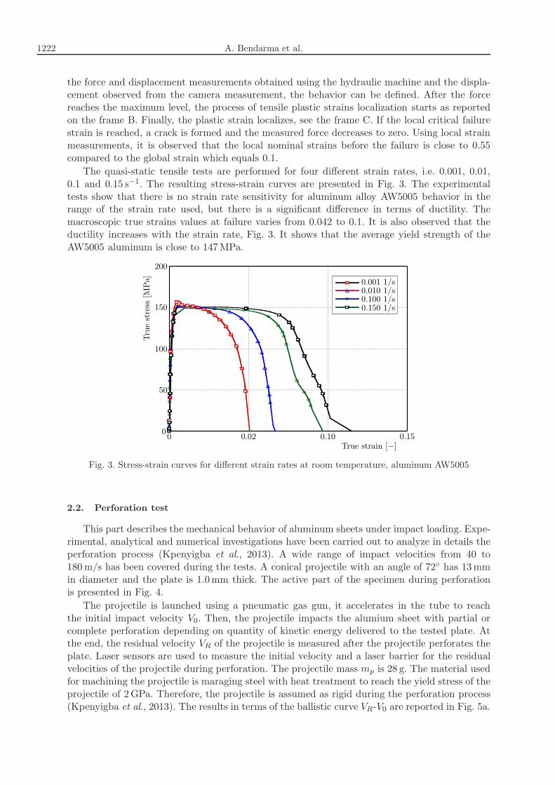
the force and displacement measurements obtained using the hydraulic machine and the displa-cement observed from the camera measurement, the behavior can be defined. After the forcereaches the maximum level, the process of tensile plastic strains localization starts as reportedon the frame B. Finally, the plastic strain localizes, see the frame C. If the local critical failurestrain is reached, a crack is formed and the measured force decreases to zero. Using local strainmeasurements, it is observed that the local nominal strains before the failure is close to 0.55compared to the global strain which equals 0.1.
The quasi-static tensile tests are performed for four different strain rates, i.e. 0.001, 0.01,0.1 and 0.15 s−1. The resulting stress-strain curves are presented in Fig. 3. The experimentaltests show that there is no strain rate sensitivity for aluminum alloy AW5005 behavior in therange of the strain rate used, but there is a significant difference in terms of ductility. Themacroscopic true strains values at failure varies from 0.042 to 0.1. It is also observed that theductility increases with the strain rate, Fig. 3. It shows that the average yield strength of theAW5005 aluminum is close to 147MPa.
Fig. 3. Stress-strain curves for different strain rates at room temperature, aluminum AW5005
2.2. Perforation test
This part describes the mechanical behavior of aluminum sheets under impact loading. Expe-rimental, analytical and numerical investigations have been carried out to analyze in details theperforation process (Kpenyigba et al., 2013). A wide range of impact velocities from 40 to180m/s has been covered during the tests. A conical projectile with an angle of 72◦ has 13mmin diameter and the plate is 1.0mm thick. The active part of the specimen during perforationis presented in Fig. 4.
The projectile is launched using a pneumatic gas gun, it accelerates in the tube to reachthe initial impact velocity V0. Then, the projectile impacts the alumium sheet with partial orcomplete perforation depending on quantity of kinetic energy delivered to the tested plate. Atthe end, the residual velocity VR of the projectile is measured after the projectile perforates theplate. Laser sensors are used to measure the initial velocity and a laser barrier for the residualvelocities of the projectile during perforation. The projectile mass mp is 28 g. The material usedfor machining the projectile is maraging steel with heat treatment to reach the yield stress of theprojectile of 2GPa. Therefore, the projectile is assumed as rigid during the perforation process(Kpenyigba et al., 2013). The results in terms of the ballistic curve VR-V0 are reported in Fig. 5a.

Experimental and numerical analysis of aluminum alloy AW5005... 1223
Fig. 4. Dimensions of the projectile and target used during perforation tests
Fig. 5. (a) Ballistic curve obtained during perforation and determination of ballistic limit, (b) energyabsorbed by plate during impact test, determination of failure energy
The residual velocity of the projectile can be calculated using the following equation proposedby Recht and Ipson (1963)
VR = (Vκ0 − V
κB )
1
κ (2.1)
where V0 is the initial velocity and VB is the ballistic velocity. In the above equation, the constantsVB is equal to 40m/s, and κ is the ballistic curve shape parameter equal to 1.65.The energy absorbed by the plate Ed can be calculated using the following equation
Ed =mP2(V 20 − V
2R) (2.2)
The difference of the initial and residual kinetic energy can be calculated using the experi-mental data, then based on the Recht-Ipson approximation, the energy absorbed by the plate canbe calculated, see Fig. 5b. Using Eq. (2.2), the minimum energy to perforate is 28 J (mP = 28 gand V0 = VB = 40m/s).In Fig. 6, for the initial impact velocity of V0 = 85m/s, the failure pattern is presented
with four petals for the residual velocity of VR = 66.5m/s. The same failure is observed forV0 = 132.3m/s with VR = 120.2m/s, respectively. The number of petals is equal to 4 in thewhole range of impact velocities, i.e. from 40 to 180m/s. A complete description concerning thenumber of petals depending on the projectile shape and the failure mode was published anddiscussed in details in (Atkins and Liu, 1998).

1224 A. Bendarma et al.
Fig. 6. Experimental observation of failure patterns, V0 = 85.3m/s and 132.3m/s
3. Johnson-Cook material model
Using experimental tests, the parameters of the Johnson-Cook (JC) model (Johnson and Cook,1983) have been identified and used to simulate tension and perforation tests. The thermo--viscoplastic behavior of AW5005 aluminum alloy is defined as follows
σ = (A+Bεnpl)(
1 + C lnεplε0
)
(1− T ∗m) (3.1)
where A is the yield stress, B and n are strain hardening coefficients, C is the strain ratesensitivity coefficient, ε0 is the strain rate reference value and m is the temperature sensiti-vity parameter. In this work, isothermal conditions are assumed. Therefore, the last term ofthe JC model related to the non-dimensional temperature T ∗ is not considered. All numericalsimulations are done at room temperature T = 300K.The material constants are obtained by experimental tests. The parameter C has been cal-
culated using the presented experimental tests for a quasi-static loading (strain rates from 0.001to 0.15 s−1). In this range small strain rates sensitivity has been observed. The optimizationusing the minimum least square method gives the value of C equal to 0.003. These constantsare shown in Table 1.
Table 1. Material parameters for the Johnson-Cook model
A [MPa] B [MPa] n [–] C [–]
147 60 0.9 0.003
In order to define the material behavior completely, a failure criterion was proposed byJohnson and Cook (1985). When mixed with their classical constitutive law, Eq. (3.1), it enabledone to reflect failure modes of structures or materials.The Johnson-Cook failure model is applied widely because of the simplicity of formulation.
A number of material parameters that are available in literature were provided by Johnsonand Holmquist (1989). However, Johnson and Cook only determined the positive range of thestress triaxiality based on some tensile tests and shear tests, and no small or negative values ofstress triaxiality were expressed. In order to effectively apply the Johnson-Cook fracture model,researchers extended the model in different ways. Liu et al. (2014) proved that the Johnson-Cookfracture model can be used as damage initiation coupled with damage evolution in metal cuttingsimulations. Moreover, the damage evolution combines two different fracture modes effects.In Fig. 7, the progressive damage model is used for aluminum alloy. The description includes
the elastic part with E0 (part a-b) and the plasticity range (b-c). The damage initiation with theJC criterion can be expressed by Eq. (3.2) (c). Along the line (c-e), the damage variable evolutiongrows from 0 to the maximum degradation ratio Dmax (d), therefore, stiffness of the material is

Experimental and numerical analysis of aluminum alloy AW5005... 1225
degraded and reduced to (1−D)E0 where D is the damage variable and E0 is the initial Youngmodulus. The damage evolution is described by mesh-independent measurements (displacementat failure and damage energy dissipation) in the model. A linear evolution damage rule is usedby defining a value of displacement at failure uf (e). Thus, the maximum degradation of stiffnessas well as the maximum damage have been taken finally as the failure criterion (d). The elementafter reaching the failure criterion is deleted from the mesh in simulation.
Fig. 7. Schematic representation of tensile test data in stress-displacement space for elastic-plasticmaterials (ABAQUS, 2011)
The Johnson-Cook damage initiation model (Johnson and Cook, 1985; Johnson and Hol-
mquist, 1989) describes the strain at damage initiation εplD−init including effects of the stresstriaxiality, strain rate and temperature, as shown in the following equation
εplD−init = [d1 + d2 exp(−d3η)](
1 + d4 lnε
ε0
)
(1 + d5T∗) (3.2)
where d1, d2, d3, d4, d5 are material parameters, η is the stress triaxiality factor, ε0 is the referencestrain rate and T ∗ is the non-dimensional temperature. The first bracket in Eq. (3.2) concerns
the influence of the stress triaxiality factor on the value of strain at damage initiation εplD−init.The value of the first bracket decreases as the stress triaxiality factor increases. The secondbracket represents the influence of the strain rate on that value, while the third one representsthe effect of thermal softening.
Table 2. Failure parameters for tension and perforation
Tensile test Perforation testTest 1 4 3 4
103 s−1 104 s−1(0.001 s−1) (0.01 s−1) (0.1 s−1) (0.15 s−1)
Damage initiation strain εplD−init 0.008 0.03 0.08 0.12 0.9 0.96
Displacement at failure uf 0.0008m
Max. degradation Dmax 0.6
By using those analytical approaches coupled to experiment results, the failure parametershave been deduced and used in the numerical model for both traction and perforation tests.They are presented in Table 2. The tensile test values are obtained from experiments, whereasthe perforation test values are obtained using a numerical analysis and available literature datafor similar materials (Jankowiak et al., 2013, 2014; Kpenyigba et al., 2013). The strain rates forperforation tests ε = 1000 s−1 and ε = 10000 s−1 correspond to initial impact velocities V0 of120m/s and 180m/s, respectively. They have been observed locally using numerical simulations.

1226 A. Bendarma et al.
4. Numerical approach
Numerical models are built using Abaqus/Explicit. The tests using this numerical model areconducted at different strain rates in quasi-static and dynamic conditions with impact velocitiesup to 180m/s. The shell element type S4R with 8 degrees of freedom and 4 nodes with reducedintegration (ABAQUS, 2011) have been used. The same element type with the element size of0.5mm×0.5mm has been proposed for tension and perforation analysis as presented in Fig. 9a.The effectiveness of such elements for this type of analysis was previously proved by Ambatiand Lorenzis (2016), Amiri et al. (2014), Elnasri and Zhao (2016).
In order to extend experimental results, some other thickness of the aluminum plate hasbeen added for both tensile and perforation simulations, therefore, thicknesses of 1.0mm and1.5mm have been used.
4.1. Modelling procedures of tensile and perforation tests
In order to verify the Johnson-Cook constitutive and failure models, tension and perforationtests have been simulated using Abaqus/Explicit version 6.14.
4.1.1. Tensile test
The aim of this numerical analysis has been to reproduce experimental results by checkingthe observed failure mode. The constitutive parameters have been identified based on the experi-mental tests. The constants are reported in Table 1. The number of elements used for meshing is16356, and 16731 is the total number of nodes. The distribution of the equivalent plastic strainscalled PEEQ in Abaqus is presented in Fig. 8b.
Fig. 8. Numerical simulation of tensile test, (a) equivalent plastic strain distribution for macroscopicstrain equal to ε = 0.04, (b) equivalent plastic strain distribution for macroscopic strain ε = 0.045
The numerical simulations are in agreement with experimental observations where the failuremode is by shearing, see Fig. 2c.

Experimental and numerical analysis of aluminum alloy AW5005... 1227
4.1.2. Perforation test
The optimal mesh has been obtained using a convergence method (stability of the resultswithout mesh dependency). The mesh is denser in the projectile-plate contact zone, thickness ofthe plate in this area is 1.0mm and the velocity is defined in predefined fields with the range ofimpact velocities from 40 to 180m/s as conceded in the experiment. This model contains 6048elements in the central part of impact and 6161 using the same element size (0.5mm×0.5mm).
The ballistic curves are reported in the following Section and compared to the experimentalresults. The interior zone of the model allows one to initiate the process of crack propagation ina precise way. The projectile behavior has been defined as rigid, because a kinematic couplingconstraint (rigid body) has been applied to avoid deformation of the projectile. The frictioncoefficient is assumed to be equal to 0.2.
Fig. 9. Numerical model used during numerical simulations and mesh density distribution: (a) mesh,(b) equivalent plastic strain distribution for macroscopic strain ε
A decrease of the number of petals with a nose angle of 72◦ has been observed when thevalue of failure strain is changed. An analytical model for prediction of the number of petalsproposed by Atkins and Liu (1998) has been used and confirmed by FE simulations.
4.2. Failure criterion model
4.3. Model I (Johnson-Cook model)
Using values illustrated in Table 2, the parameters are used to identify the Johnson-Cookdamage initiation model. The triaxiality dependent part is neglected because the triaxialityin all cases is 1/3. The influence of temperature is also ignored since there is no effect on allstrain rates captured by the temperature camera that have been used during the tests. The finalequation used to determine the Johnson-Cook damage initiation strain εplD−init as a function ofstrain rates ε corresponding to aluminum alloy is
εplD−init = [d1][
1 + d4 lnε
ε0
]
(4.1)
In order to determine the parameters d1, d4, an algorithm with Matlab optimization using Eq.(4.1) has been developed, and the adopted values are presented in Table 3.

1228 A. Bendarma et al.
Fig. 10. Plot of damage initiation strain versus plastic strain rate using Model I JC), Eq. (4.1)
For tensile tests cases 2, 3 and 4, the damage initiation Johnson-Cook model gives too highvalues of the initial damage strain because it is linear in the interval of the strain rate. Finally,the global behavior in space stress-strain is too ductile, therefore, another approach has beenproposed.
4.3.1. Failure modeling using optimized Model II
Another function has been proposed to better fit the damage initiation model. This function(Eq. (4.2)) contains three constants E, F and G to be determined by using an optimizationalgorithm. The constants are reported in Table 3
εplD−init = Gexp(E + F ε)
1 + exp(E + F ε)(4.2)
As demonstrated in Fig. 11, there is a good correlation between the fitted curve, the expe-rimental and numerical values, however, there is still a bit of miss-match between some pointsin the middle of the curve.
Fig. 11. Plot of damage initiation strain versus plastic strain rate using optimized Model II, Eq. (4.2)

Experimental and numerical analysis of aluminum alloy AW5005... 1229
4.3.2. Failure modeling using Model III
The next damage initiation criterion (Eq. (4.3)) is defined with two glued functions with fourconstants H, I, J and K. Using an optimization method, a good correlation in a wide range ofstrain rates is obtained (see Fig. 12)
εplD−init =
{
f(ε) = H exp(I log10 ε) if ε ¬ εtransmition
g(ε) = J −K exp(log10 ε) if ε εtransmition(4.3)
The estimated constants are reported in Table 3 with εtransmition = 1 s−1.
Table 3. Parameters for failure models
Model I (JC) Model II Model III
d1 [–] d4 [–] E [–] F [–] G [–] H [–] I [–] J [–] K [–]
0.007 78.722 −0.89 1.13 1.0085 −0.398 1.4523 1.0085 0.6647
Fig. 12. Plot of failure strain versus plastic strain rate using optimized Model III
5. Comparison of numerical and experimental results
5.1. Tensile test comparisons
A comparison has been made between three initiation damage models using test number 3.As it is presented in Fig. 13, the best results are obtained with Model III. This is why this modelhas been adopted for an other analysis.
Initiation damage Model III has been implemented into the numerical model and then com-pared with the experimental data for different strain rates (0.001, 0.01, 0.1 and 0.15 s−1). Theresults are shown in Fig. 14.
As it might be seen in Fig. 15, there is a good correlation between the experimental andnumerical results. In the case of test 3, the numerical model has demonstrated more ductilebehavior at the failure start, whereas for test 4, it has revealed ductility at the terminal phaseof failure.

1230 A. Bendarma et al.
Fig. 13. Comparison between experimental and numerical curves using 3 failure criteria
Fig. 14. Comparison between experimental and numerical curves using optimized initiationdamage model (Model III)
Fig. 15. Numerical result for conical projectile shape, V0 = 120m/s, comparison betweenexperiments and simulations
5.2. Perforation test comparison
During this study, the same model (Model III) has been used to compare the numerical andexperimental results in the dynamic field using the perforation process in Abaqus/Explicit witha wide range of impact velocities from 40 to 180m/s and with target thicknesses of 1.0 and

Experimental and numerical analysis of aluminum alloy AW5005... 1231
1.5mm. As it is shown in Fig. 15, the number of petals is the same as in the experiments, fourpetals are observed. It was reported in (Atkins and Liu, 1989; Landkof and Goldsmith, 1985)that the number of petals N observed during dynamic perforation coupled to a conical projectileshape was related to the nose angle φ. In this work, one angle (72◦) has been used to analyze theresults. In (Kpenyigba et al., 2013) during the analysis of results it was observed that generallythe number of petals N decreased when the projectile angle φ/2 increased.Figure 16 contains both the experimental and the numerical results of simulations with
the same interval of velocity. Damage initiation criterion Model III has been used to verify thecorrelation between the numerical curve and the experiment. There is a good correlation betweenthe experimental and numerical results which adds to the credibility of correctness of the failurecriterion model. It can be observed that for thicker plates than 1.5mm, the value of the ballisticlimit is shifted from 40m/s to 50m/s.
Fig. 16. The ballistic curve in experiment and in simulation
6. Conclusions
Mechanical characteristics of new aluminum alloy AW5005 have been investigated. The identi-fication of material parameters has been done using the coupling of the simulation and expe-rimental techniques. Additionally, three damage initiation criteria have been used in numericalmodelling for both tension and perforation simulations. A good agreement has been observedbetween the experimental results and FE simulations in terms of the stress-strain curve and bal-listic curves as well as the energy absorbed. It confirms the correctness of the damage initiationcriterion.The future work will investigate the behavior of a composite material in form of a sandwich
structure with two plates of aluminum (AW5005) and one internal layer of polyethylene.
References
1. ABAQUS, Abaqus/Explicit User’s Manuals, version 6.11, 2011
2. Ambati M., De Lorenzis L., 2016, Phase-field modeling of brittle and ductile fracture in shellswith isogeometric NURBS-based solid-shell elements, Computer Methods in Applied Mechanics andEngineering, DOI: 10.1016/j.cma.2016.02.017

1232 A. Bendarma et al.
3. Amiri F., Millan D., Shen Y., Rabczuk T., Arroyo M., 2014, Phase-field modeling offracture in linear thin shells, Theoretical and Applied Fracture Mechanics, 69, 102-109
4. Atkins A.G., Liu J.H., 1998, Necking and radial cracking around perforations in thin sheets atnormal incidence, International Journal of Impact Engineering, 21, 521-539
5. Bao Y., Wierzbicki T., 2004, On fracture locus in the equivalent strain and stress triaxialityspace, International Journal of Mechanical Sciences, 46, 81-98
6. Børvik T., Hopperstad O.S., Langseth M., Malo K.A., 2003, Effect of target thickness inblunt projectile penetration of Weldox 460E steel plates, International Journal of Impact Engine-ering, 28, 413-464
7. Børvik T., Dey S., Clausen A.H., 2009, Perforation resistance of five different high-strengthsteel plates subjected to small-arms projectiles, International Journal of Impact Engineering, 36,948-964
8. Elnasri I., Zhao H., 2016, Impact perforation of sandwich panels with aluminum foam core: anumerical and analytical study, International Journal of Impact Engineering, 96, 50-60
9. Erice B., Perez-Martın M.J., Galvez F., 2014, An experimental and numerical study of ducti-le failure under quasi-static and impact loadings of Inconel 718 nickel-base superalloy, InternationalJournal of Impact Engineering, 69, 11-24
10. Hancock J.W., Mackenzie A.C., 1976, On the mechanisms of ductile failure in high-strengthsteels subjected to multi-axial stress-states, Journal of the Mechanics and Physics of Solids, 24,147-160
11. Jankowiak T., Rusinek A., Kpenyigba K.M., Pesci R., 2014, Ballistic behavior of steel sheetsubjected to impact and perforation, Steel and Composite Structures, 16, 595-609
12. Jankowiak T., Rusinek A., Wood P., 2013, A numerical analysis of the dynamic behavior ofsheet steel perforated by a conical projectile under ballistic conditions, Finite Elements in Analysisand Design, 65, 39-49
13. Johnson G.R., Cook W.H., 1983, A constitutive model and data for metals subjected to largestrains, high strain rates and high temperatures, Proceedings of the 7th International Symposiumon Ballistics, 21, 541-547
14. Johnson G.R., Cook W.H., 1985, Fracture characteristics of three metals subjected to variousstrains, strain rates, temperatures and pressures, Engineering Fracture Mechanics, 21, 1, 31-48
15. Johnson G.R., Holmquist T.J., 1989, Test data and computational strength and fracture modelconstants for 23 materials subjected to large strains, high strain rates, and high temperatures. LosAlamos National Laboratory, Los Alamos, NM, Report No. LA-11463-MS
16. Kpenyigba K.M., Jankowiak T., Rusinek A., Pesci R., 2013, Influence of projectile shapeon dynamic behavior of steel sheet subjected to impact and perforation, Thin-Walled Structures,65, 93-104
17. Kulekci M.K., 2014, Effect of the process parameters on tensile shear strength of friction stirspot welded aluminum alloy (EN AW5005), Archives of Metallurgy and Materials, 59, 221-224
18. Landkof, B., Goldsmith, W., 1985, Petalling of thin, metallic plates during penetration bycylindro-conical projectiles, International Journal of Solids and Structures, 21, 245-266
19. Liu J., Bai Y., Xu C., 2014, Evaluation of ductile fracture models in finite element simulation ofmetal cutting processes, Journal of Manufacturing Science and Engineering, 136, 011010
20. Quinney H., Taylor G.I., 1937, The emission of the latent energy due to previous cold workingwhen a metal is heated, Proceedings of the Royal Society of London. Series A, Mathematical andPhysical Sciences, 157-181
21. Recht R.F., Ipson T.W., 1963, Ballistic perforation dynamics, Journal of Applied Mechanics,30, 384-390

Experimental and numerical analysis of aluminum alloy AW5005... 1233
22. Rusinek A., Klepaczko J.R., 2001, Shear testing of a sheet steel at wide range of strain rates anda constitutive relation with strain-rate and temperature dependence of the flow stress, InternationalJournal of Plasticity, 17, 87-115
23. Rusinek A., Rodrıguez-Martınez J.A., 2009, Thermo-viscoplastic constitutive relation foraluminum alloys, modeling of negative strain rate sensitivity and viscous drag effects, Materialsand Design, 30, 4377-4390
24. Rusinek A., Rodrıguez-Martınez J.A., Arias A., Klepaczko J.R., López-Puente J.,2008, Influence of conical projectile diameter on perpendicular impact of thin steel plate, Engine-ering Fracture Mechanics, 75, 2946-2967
25. Verleysen P., Peirs J., Van Slycken J., Faes K., Duchene L., 2011, Effect of strain rate onthe forming behaviour of sheet metals, Journal of Materials Processing Technology, 211, 1457-1464
26. Zhong W.Z., Rusinek A., Jankowiak T., Abed F., Bernier R., Sutter G., 2015, Influenceof interfacial friction and specimen configuration in Split Hopkinson Pressure Bar system, TribologyInternational, 90, 1-14
27. Xue L., Mock W., Belytschko T., 2010, Penetration of DH-36 steel plates with and withoutpolyurea coating, Mechanics of Materials, 42, 981-1003
28. Zhong W.Z., Mbarek I.A., Rusinek A., Bernier R., Jankowiak T., Sutter G., 2016,Development of an experimental set-up for dynamic force measurements during impact and perfo-ration, coupling to numerical simulations, International Journal of Impact Engineering, 91, 102-115
Manuscript received January 3, 2017; accepted for print May 9, 2017