Embed Size (px)
Citation preview
HAL Id: hal-01457277https://hal.archives-ouvertes.fr/hal-01457277
Submitted on 6 Feb 2017
HAL is a multi-disciplinary open accessarchive for the deposit and dissemination of sci-entific research documents, whether they are pub-lished or not. The documents may come fromteaching and research institutions in France orabroad, or from public or private research centers.
L’archive ouverte pluridisciplinaire HAL, estdestinée au dépôt et à la diffusion de documentsscientifiques de niveau recherche, publiés ou non,émanant des établissements d’enseignement et derecherche français ou étrangers, des laboratoirespublics ou privés.
Experimental testing of a low-temperature organicRankine cycle (ORC) engine coupled with concentrating
PV/thermal collectors: Laboratory and field testsGeorge Kosmadakis, Arnaud Landelle, Marija Lazova, Dimitris Manolakos,
Alihan Kaya, Henk Huisseune, Christos-Spyridon Karavas, Nicolas Tauveron,Remi Revellin, Philippe Haberschill, et al.
To cite this version:George Kosmadakis, Arnaud Landelle, Marija Lazova, Dimitris Manolakos, Alihan Kaya, et al.. Ex-perimental testing of a low-temperature organic Rankine cycle (ORC) engine coupled with concen-trating PV/thermal collectors: Laboratory and field tests. Energy, Elsevier, 2016, 117, pp.222 - 236.�10.1016/j.energy.2016.10.047�. �hal-01457277�
lable at ScienceDirect
Energy 117 (2016) 222e236
Contents lists avai
Energy
journal homepage: www.elsevier .com/locate/energy
Experimental testing of a low-temperature organic Rankine cycle(ORC) engine coupled with concentrating PV/thermal collectors:Laboratory and field tests
George Kosmadakis a, *, Arnaud Landelle b, c, d, 1, Marija Lazova e, 1, Dimitris Manolakos a,Alihan Kaya e, Henk Huisseune e, Christos-Spyridon Karavas a, Nicolas Tauveron b,Remi Revellin c, Philippe Haberschill c, Michel De Paepe e, George Papadakis a
a Department of Natural Resources and Agricultural Engineering, Agricultural University of Athens, Iera Odos Street 75, Athens 11855, Greeceb CEA, LITEN, DTBH, SBRT, LS2T, 17 rue des Martyrs, F-38054 Grenoble, Francec Universit�e de Lyon, INSA Lyon, CETHIL UMR5008, F-69621 Villeurbane, Franced ADEME, 20 Avenue du Gr�esill�e, 49004 Angers, Francee Department of Flow, Heat and Combustion Mechanics, Ghent University, Sint-Pietersnieuwstraat 41, Ghent 9000, Belgium
a r t i c l e i n f o
Article history:Received 27 April 2016Received in revised form12 August 2016Accepted 17 October 2016Available online 28 October 2016
Keywords:Organic Rankine cycleConcentrating PV/thermalLow-temperatureScroll expanderEvaporatorDiaphragm pump
* Corresponding author.E-mail address: [email protected] (G. Kosmadakis)URL: http://www.renewables.aua.gr/
1 Second and third author have equal contribution
http://dx.doi.org/10.1016/j.energy.2016.10.0470360-5442/© 2016 Elsevier Ltd. All rights reserved.
a b s t r a c t
A detailed experimental investigation of a small-scale low-temperature organic Rankine cycle (ORC) withR-404A is presented. The tests are first conducted at laboratory conditions for detailed evaluation of themain components at both design and off-design conditions, for variable heat input up to 48 kWth and hotwater temperature in the range of 65e100 �C. A scroll compressor in reverse operation is used asexpansion machine and a dedicated helical coil heat exchanger is installed, suitable for high-pressure andtemperature operation. The ORC pump is a diaphragm pump coupled with an induction motor. Therotational speeds of both the expander and pump are regulated with frequency inverters, in order to havethe full control of the engine operation. The ORC has been then connected with concentrating PV/thermal collectors, which produce electricity and heat and provide it to the ORC. These field tests are alsopresented with the overall focus on the performance of the whole ORC unit and its power contribution tothe solar field. The tests have revealed that such low-temperature ORC unit can have adequate efficiencyand that its coupling with a solar field is feasible, increasing the power production of the whole system.
© 2016 Elsevier Ltd. All rights reserved.
1. Introduction
The organic Rankine cycle (ORC) technology is suitable for heatrecovery applications of temperature even lower than 100 �C [1]. Atsuch conditions its efficiency is rather low, usually in the range of4e6%, but still there are cases where it can be cost effective,especially for waste heat recovery. The main advantage at thistemperature range is the simple and low-cost heat source circuit,since even liquid water can be used at low-pressure, while the useof thermal oil is avoided. Moreover, a simple ORC configuration canbe considered with a single expansion machine and no internalheat exchangers [2,3].
.
.
The challenge is even bigger in small-scale systems with powerproduction of few kW. In such cases although the design is rathersimple to reduce costs, a very careful selection of each component iscrucial, in order to keep an adequate performance. Moreover, low-temperature operation (below 100 �C) brings some additional re-strictions, since a limited number of organic working fluids can beused for such purposes. The most important components in ORCengines are: 1. the ORC pump, for which low attention is givenmostof the times, 2. the expansion machine with intensive researcheffort for producing/adapting expanders suitable for a wide powerrange (of positive displacement type or even turbines for largersystems), and 3. the evaporator, for which new correlations need tobe developed for designing a heat exchanger suitable to operate inORC conditions. When operating at low temperature, thecondenser also becomes an important component, since thermalefficiency becomes highly sensitive to the temperature of the heatrejection medium.
G. Kosmadakis et al. / Energy 117 (2016) 222e236 223
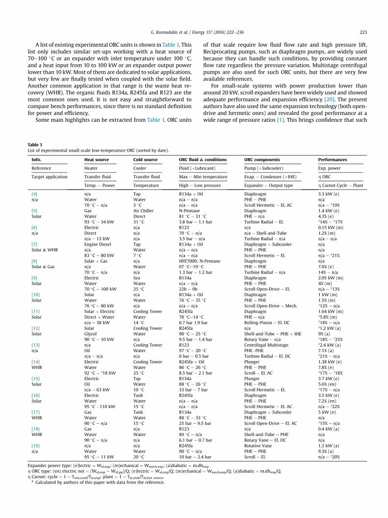
A list of existing experimental ORC units is shown in Table 1. Thislist only includes similar set-ups working with a heat source of70e100 �C or an expander with inlet temperature under 100 �C,and a heat input from 10 to 100 kW or an expander output powerlower than 10 kW. Most of them are dedicated to solar applications,but very few are finally tested when coupled with the solar field.Another common application in that range is the waste heat re-covery (WHR). The organic fluids R134a, R245fa and R123 are themost common ones used. It is not easy and straightforward tocompare bench performances, since there is no standard definitionfor power and efficiency.
Some main highlights can be extracted from Table 1. ORC units
Table 1List of experimental small-scale low-temperature ORC (sorted by date).
Info. Heat source Cold source ORC fluid &
Reference Heater Cooler Fluid (þLub
Target application Transfer fluid Transfer fluid Max e Min
Temp. e Power Temperature High e Low
[4] n/a Tap R134a þ Oin/a Water Water n/a e n/a
70 �C e n/a 5 �C n/a e n/a[5] Gas Air Chiller N-PentaneSolar Water Direct 81 �C e 31
93 �C e 34 kW 31 �C 3.8 bar e 1.[6] Electric n/a R123n/a Direct n/a 70 �C e n/a
n/a e 13 kW n/a 3.5 bar e n/[7] Engine Diesel Tap R134a þ OiSolar & WHR n/a Water n/a e n/a
83 �C e 80 kW 7 �C n/a e n/a[8] Solar þ Gas n/a HFE7000; NSolar & Gas n/a Water 67 �Ce19 �C
70 �C e n/a n/a 1.3 bar e 1.[9] Electric Sea R134aSolar Water Water n/a e n/a
70 �C e 100 kW 25 �C 22b e 9b[10] Solar n/a R134a þ OiSolar Water Water 76 �C e 35
76 �C e 80 kW n/a n/a e n/a[11] Solar þ Electric Cooling Tower R245faSolar Direct þ Water Water 78 �Ce14 �C
n/a e 38 kW 14 �C 6.7 bar 1.9 b[12] Solar Cooling Tower R245faSolar Glycol Water 90 �C e 25
90 �C e 10 kW n/a 9.5 bar e 1.[13] n/a Cooling Tower R123n/a Oil Water 97 �C e 20
n/a e n/a n/a 6 bar e 0.5[14] Electric Cooling Tower R245fa þ OWHR Water Water 86 �C e 26
92 �C e a18 kW 25 �C 8.5 bar e 2.[15] Electric Tap R134aSolar Oil Water 88 �C e 26
n/a e 63 kW 10 �C 33 bar e 7 b[16] Electric Tank R245faSolar Water Water n/a e n/a
95 �C �110 kW 15 �C n/a e n/a[17] Gas Tank R134aWHR Water Water 88 �C e 33
90 �C e n/a 15 �C 25 bar e 9.5[18] Gas n/a R123WHR Water Water 89 �C e n/a
90 �C e n/a n/a 6.1 bar e 0.[19] n/a n/a R245fan/a Water Water 90 �C e n/a
95 �C e 11 kW 20 �C 10 bar e 2.4
Expander power type: (e)lectric ¼ Wel,exp; (m)echanical ¼ Wmech,exp; (a)diabatic ¼ m.dhh ORC type: (en) electric net ¼ (Wel,exp e Wel,pp)/Q; (e)lectric ¼ Wel,exp/Q; (m)echanicalh Carnot: cycle ¼ 1 e Tout,cond/Tin,exp; plant ¼ 1 e Tin,sink/Tin,hot source.
a Calculated by authors of this paper with data from the reference.
of that scale require low fluid flow rate and high pressure lift.Reciprocating pumps, such as diaphragm pumps, are widely usedbecause they can handle such conditions, by providing constantflow rate regardless the pressure variation. Multistage centrifugalpumps are also used for such ORC units, but there are very fewavailable references.
For small-scale systems with power production lower thanaround 20 kW, scroll expanders have beenwidely used and showedadequate performance and expansion efficiency [20]. The presentauthors have also used the same expansion technology (both open-drive and hermetic ones) and revealed the good performance at awide range of pressure ratios [1]. This brings confidence that such
conditions ORC components Performances
ricant) Pump (þSubcooler) Exp. power
temperature Evap. e Condenser (þIHE) h ORC
pressure Expander e Output type h Carnot Cycle e Plant
l Diaphragm 3.3 kW (e)PHE e PHE n/aScroll Hermetic e El. AC n/a e a19%Diaphragm 1.4 kW (e)
�C PHE e n/a 4.3% (e)1 bar Turbine Radial e El. a14% e a17%
n/a 0.15 kW (m)n/a e Shell-and-Tube 1.2% (m)
a Turbine Radial e n/a n/a e n/al Diaphragm þ Subcooler n/a
PHE e PHE n/aScroll Hermetic e El. n/a e a21%
-Pentane Diaphragm n/aPHE e PHE 7.6% (e)
2 bar Turbine Radial e n/a 14% e n/aDiaphragm 2.05 kW (m)PHE e PHE 4% (m)Scroll Open-Drive e El. n/a e a13%
l Diaphragm 1 kW (m)�C PHE e PHE 1.5% (m)
Scroll Open-Drive e Mech. a12% e n/aDiaphragm 1.64 kW (m)PHE e n/a a5.8% (m)
ar Rolling-Piston e El. DC a18% e n/an/a a1.2 kW (a)
�C Shell-and-Tube e PHE þ IHE 9% (a)4 bar Rotary Vane e n/a a18% e a25%
Centrifugal Multistage a2.4 kW (a)�C PHE -PHE 7.1% (a)bar Turbine Radial e El. DC a21% e n/ail Plunger 1.38 kW (e)�C PHE e PHE 7.8% (e)1 bar Scroll e El. AC a17% e a18%
Plunger 3.7 kW (e)�C PHE e PHE 5.6% (en)ar Scroll Hermetic e El. a17% e n/a
Diaphragm 3.5 kW (e)PHE e PHE 7.2% (en)Scroll Hermetic e El. AC n/a e a22%Diaphragm þ Subcooler 5 kW (e)
�C PHE e PHE n/abar Scroll Open-Drive e El. AC a15% e n/a
n/a 0.4 kW (a)Shell-and-Tube e PHE n/a
7 bar Rotary Vane e El. DC n/aRotative Vane 1.2 kW (a)PHE e PHE 9.3% (a)
bar Scroll e El. n/a e a20%
exp.¼ Wmech,exp/Q; (a)diabatic ¼ m.dhexp/Q.
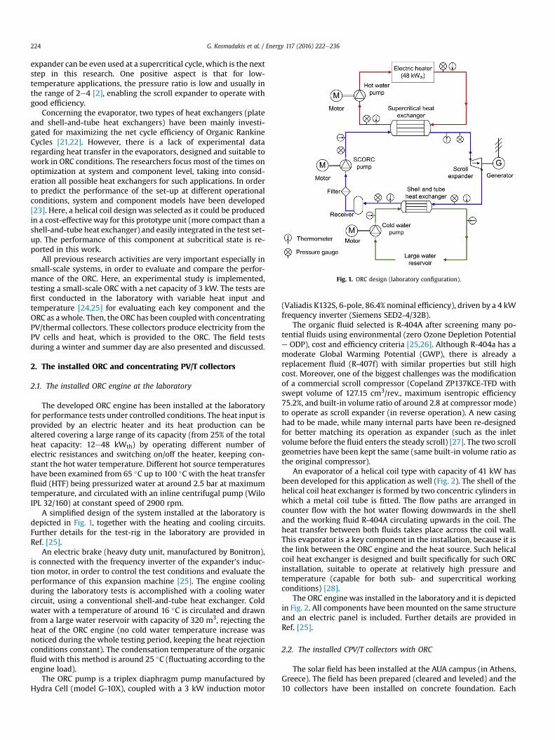
Fig. 1. ORC design (laboratory configuration).
G. Kosmadakis et al. / Energy 117 (2016) 222e236224
expander can be even used at a supercritical cycle, which is the nextstep in this research. One positive aspect is that for low-temperature applications, the pressure ratio is low and usually inthe range of 2e4 [2], enabling the scroll expander to operate withgood efficiency.
Concerning the evaporator, two types of heat exchangers (plateand shell-and-tube heat exchangers) have been mainly investi-gated for maximizing the net cycle efficiency of Organic RankineCycles [21,22]. However, there is a lack of experimental dataregarding heat transfer in the evaporators, designed and suitable towork in ORC conditions. The researchers focus most of the times onoptimization at system and component level, taking into consid-eration all possible heat exchangers for such applications. In orderto predict the performance of the set-up at different operationalconditions, system and component models have been developed[23]. Here, a helical coil designwas selected as it could be producedin a cost-effectiveway for this prototype unit (more compact than ashell-and-tube heat exchanger) and easily integrated in the test set-up. The performance of this component at subcritical state is re-ported in this work.
All previous research activities are very important especially insmall-scale systems, in order to evaluate and compare the perfor-mance of the ORC. Here, an experimental study is implemented,testing a small-scale ORC with a net capacity of 3 kW. The tests arefirst conducted in the laboratory with variable heat input andtemperature [24,25] for evaluating each key component and theORC as awhole. Then, the ORC has been coupledwith concentratingPV/thermal collectors. These collectors produce electricity from thePV cells and heat, which is provided to the ORC. The field testsduring a winter and summer day are also presented and discussed.
2. The installed ORC and concentrating PV/T collectors
2.1. The installed ORC engine at the laboratory
The developed ORC engine has been installed at the laboratoryfor performance tests under controlled conditions. The heat input isprovided by an electric heater and its heat production can bealtered covering a large range of its capacity (from 25% of the totalheat capacity: 12e48 kWth) by operating different number ofelectric resistances and switching on/off the heater, keeping con-stant the hot water temperature. Different hot source temperatureshave been examined from 65 �C up to 100 �C with the heat transferfluid (HTF) being pressurized water at around 2.5 bar at maximumtemperature, and circulated with an inline centrifugal pump (WiloIPL 32/160) at constant speed of 2900 rpm.
A simplified design of the system installed at the laboratory isdepicted in Fig. 1, together with the heating and cooling circuits.Further details for the test-rig in the laboratory are provided inRef. [25].
An electric brake (heavy duty unit, manufactured by Bonitron),is connected with the frequency inverter of the expander's induc-tion motor, in order to control the test conditions and evaluate theperformance of this expansion machine [25]. The engine coolingduring the laboratory tests is accomplished with a cooling watercircuit, using a conventional shell-and-tube heat exchanger. Coldwater with a temperature of around 16 �C is circulated and drawnfrom a large water reservoir with capacity of 320 m3, rejecting theheat of the ORC engine (no cold water temperature increase wasnoticed during the whole testing period, keeping the heat rejectionconditions constant). The condensation temperature of the organicfluid with this method is around 25 �C (fluctuating according to theengine load).
The ORC pump is a triplex diaphragm pump manufactured byHydra Cell (model G-10X), coupled with a 3 kW induction motor
(Valiadis K132S, 6-pole, 86.4% nominal efficiency), driven by a 4 kWfrequency inverter (Siemens SED2-4/32B).
The organic fluid selected is R-404A after screening many po-tential fluids using environmental (zero Ozone Depletion Potentiale ODP), cost and efficiency criteria [25,26]. Although R-404a has amoderate Global Warming Potential (GWP), there is already areplacement fluid (R-407f) with similar properties but still highcost. Moreover, one of the biggest challenges was the modificationof a commercial scroll compressor (Copeland ZP137KCE-TFD withswept volume of 127.15 cm3/rev., maximum isentropic efficiency75.2%, and built-in volume ratio of around 2.8 at compressor mode)to operate as scroll expander (in reverse operation). A new casinghad to be made, while many internal parts have been re-designedfor better matching its operation as expander (such as the inletvolume before the fluid enters the steady scroll) [27]. The two scrollgeometries have been kept the same (same built-in volume ratio asthe original compressor).
An evaporator of a helical coil type with capacity of 41 kW hasbeen developed for this application as well (Fig. 2). The shell of thehelical coil heat exchanger is formed by two concentric cylinders inwhich a metal coil tube is fitted. The flow paths are arranged incounter flow with the hot water flowing downwards in the shelland the working fluid R-404A circulating upwards in the coil. Theheat transfer between both fluids takes place across the coil wall.This evaporator is a key component in the installation, because it isthe link between the ORC engine and the heat source. Such helicalcoil heat exchanger is designed and built specifically for such ORCinstallation, suitable to operate at relatively high pressure andtemperature (capable for both sub- and supercritical workingconditions) [28].
The ORC engine was installed in the laboratory and it is depictedin Fig. 2. All components have been mounted on the same structureand an electric panel is included. Further details are provided inRef. [25].
2.2. The installed CPV/T collectors with ORC
The solar field has been installed at the AUA campus (in Athens,Greece). The field has been prepared (cleared and leveled) and the10 collectors have been installed on concrete foundation. Each
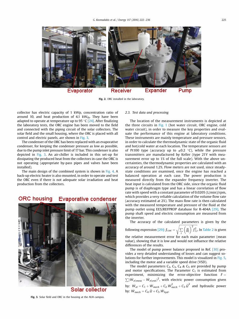
Fig. 2. ORC installed in the laboratory.
G. Kosmadakis et al. / Energy 117 (2016) 222e236 225
collector has electric capacity of 1 kWp, concentration ratio ofaround 10, and heat production of 4.1 kWth. They have beenadapted to operate at temperature up to 95 �C [24]. After finalizingthe laboratory tests, the ORC engine has been moved to the fieldand connected with the piping circuit of the solar collectors. Thesolar field and the small housing, where the ORC is placed with allcontrol and electric panels, are shown in Fig. 3.
The condenser of the ORC has been replacedwith an evaporativecondenser, for keeping the condenser pressure as low as possible,due to the pump inlet pressure limit of 17 bar. This condenser is alsodepicted in Fig. 3. An air-chiller is included in this set-up fordissipating the produced heat from the collectors in case the ORC isnot operating (appropriate by-pass pipes and valves have beeninstalled).
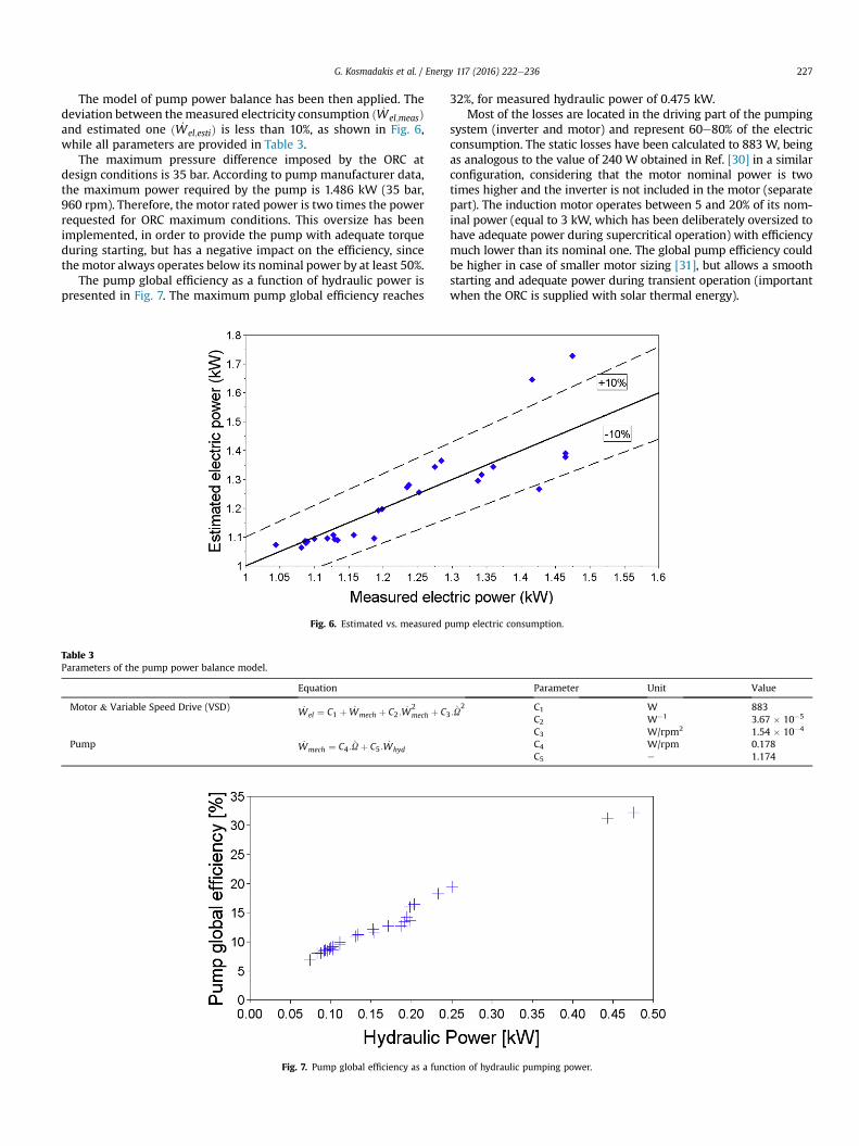
The main design of the combined system is shown in Fig. 4. Aback-up electric heater is also mounted, in order to operate and testthe ORC even if there is not adequate solar irradiation and heatproduction from the collectors.
Fig. 3. Solar field and ORC in the housing at the AUA campus.
2.3. Test data and processing
The location of the measurement instruments is depicted atthe three circuits in Fig. 1 (hot water circuit, ORC engine, coldwater circuit), in order to measure the key properties and eval-uate the performance of this engine at laboratory conditions.These instruments are mainly temperature and pressure sensors,in order to calculate the thermodynamic state of the organic fluidand hot/cold water at each location. The temperature sensors areof Pt100 type (accuracy up to ±0.2 �C), while the pressuretransmitters are manufactured by Keller (type 21Y with mea-surement error up to 1% of the full scale). With the above un-certainties, the thermodynamic properties are calculated with anaccuracy of around 1.2%. Flow meters are not used, since steady-state conditions are examined, once the engine has reached abalanced operation at each case. The power production ismeasured directly from the expander frequency inverter. Theheat input is calculated from the ORC side, since the organic fluidpump is of diaphragm type and has a linear correlation of flowrate with speed with a constant parameter of 0.0205 (L/min)/rpm,which provides a very reliable calculation of the volume flow rate(accuracy estimated at 2%). The mass flow rate is then calculatedwith the measured temperature and pressure of the fluid at thepump outlet using EES/REFPROP database for R-404A [29]. Thepump shaft speed and electric consumption are measured fromthe inverter.
The accuracy of the calculated parameters is given by the
following expression [29]: ft;tot ¼ffiffiffiffiffiffiffiffiffiffiffiffiffiffiffiffiffiffiffiffiffiffiffiffiffiffiPi
�vtvXi
�2f 2t;i
s. In Table 2 is given
the relative measurement error for each main parameter (meanvalue), showing that it is low and would not influence the relativedifferences of the results.
The model of pump power balance proposed in Ref. [30] pro-vides a very detailed understanding of losses and can suggest so-lutions for further improvements. This model is visualized in Fig. 5,including the motor and a variable speed drive (VSD).
The model parameters C2, C3, C4 & C5 are provided by pumpand motor specifications. The Parameter C1 is estimated fromexperiment, minimizing the error-objective function F ¼Pð _Wel;meas � _Wel;estiÞ2, with electric power consumption given
by: _Wel ¼ C1 þ _Wmech þ C2: _W2mech þ C3: _U
2and hydraulic power
by: _Wmech ¼ C4: _Uþ C5: _Whyd.
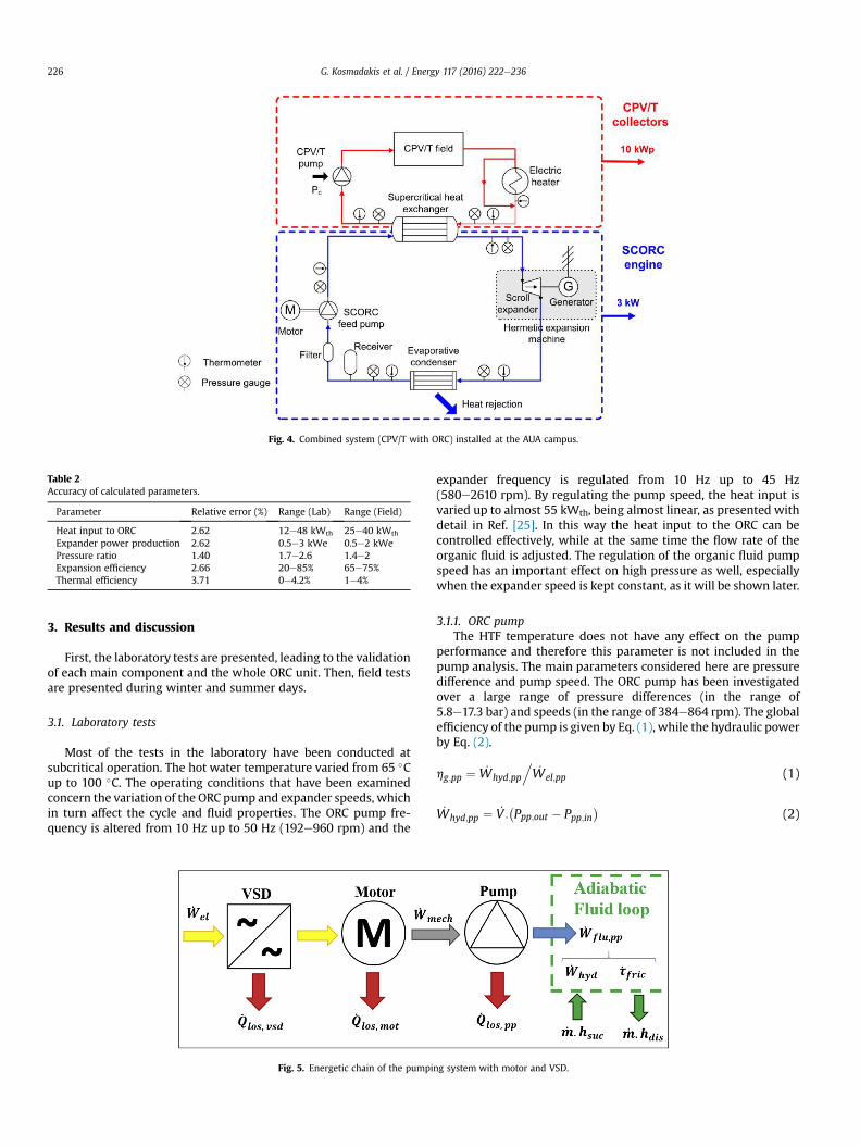
Fig. 4. Combined system (CPV/T with ORC) installed at the AUA campus.
Table 2Accuracy of calculated parameters.
Parameter Relative error (%) Range (Lab) Range (Field)
Heat input to ORC 2.62 12e48 kWth 25e40 kWth
Expander power production 2.62 0.5e3 kWe 0.5e2 kWePressure ratio 1.40 1.7e2.6 1.4e2Expansion efficiency 2.66 20e85% 65e75%Thermal efficiency 3.71 0e4.2% 1e4%
G. Kosmadakis et al. / Energy 117 (2016) 222e236226
3. Results and discussion
First, the laboratory tests are presented, leading to the validationof each main component and the whole ORC unit. Then, field testsare presented during winter and summer days.
3.1. Laboratory tests
Most of the tests in the laboratory have been conducted atsubcritical operation. The hot water temperature varied from 65 �Cup to 100 �C. The operating conditions that have been examinedconcern the variation of the ORC pump and expander speeds, whichin turn affect the cycle and fluid properties. The ORC pump fre-quency is altered from 10 Hz up to 50 Hz (192e960 rpm) and the
Fig. 5. Energetic chain of the pumpi
expander frequency is regulated from 10 Hz up to 45 Hz(580e2610 rpm). By regulating the pump speed, the heat input isvaried up to almost 55 kWth, being almost linear, as presented withdetail in Ref. [25]. In this way the heat input to the ORC can becontrolled effectively, while at the same time the flow rate of theorganic fluid is adjusted. The regulation of the organic fluid pumpspeed has an important effect on high pressure as well, especiallywhen the expander speed is kept constant, as it will be shown later.
3.1.1. ORC pumpThe HTF temperature does not have any effect on the pump
performance and therefore this parameter is not included in thepump analysis. The main parameters considered here are pressuredifference and pump speed. The ORC pump has been investigatedover a large range of pressure differences (in the range of5.8e17.3 bar) and speeds (in the range of 384e864 rpm). The globalefficiency of the pump is given by Eq. (1), while the hydraulic powerby Eq. (2).
hg;pp ¼ _Whyd;pp
._Wel;pp (1)
_Whyd;pp ¼ _V :�Ppp;out � Ppp;in
�(2)
ng system with motor and VSD.
G. Kosmadakis et al. / Energy 117 (2016) 222e236 227
The model of pump power balance has been then applied. Thedeviation between themeasured electricity consumption ð _Wel;measÞand estimated one ð _Wel;estiÞ is less than 10%, as shown in Fig. 6,while all parameters are provided in Table 3.
The maximum pressure difference imposed by the ORC atdesign conditions is 35 bar. According to pump manufacturer data,the maximum power required by the pump is 1.486 kW (35 bar,960 rpm). Therefore, the motor rated power is two times the powerrequested for ORC maximum conditions. This oversize has beenimplemented, in order to provide the pump with adequate torqueduring starting, but has a negative impact on the efficiency, sincethemotor always operates below its nominal power by at least 50%.
The pump global efficiency as a function of hydraulic power ispresented in Fig. 7. The maximum pump global efficiency reaches
Fig. 6. Estimated vs. measured p
Table 3Parameters of the pump power balance model.
Equation
Motor & Variable Speed Drive (VSD) _Wel ¼ C1 þ _Wmech þ C2: _W2mech þ C3
Pump _Wmech ¼ C4: _Uþ C5: _Whyd
Fig. 7. Pump global efficiency as a func
32%, for measured hydraulic power of 0.475 kW.Most of the losses are located in the driving part of the pumping
system (inverter and motor) and represent 60e80% of the electricconsumption. The static losses have been calculated to 883 W, beingas analogous to the value of 240 W obtained in Ref. [30] in a similarconfiguration, considering that the motor nominal power is twotimes higher and the inverter is not included in the motor (separatepart). The induction motor operates between 5 and 20% of its nom-inal power (equal to 3 kW, which has been deliberately oversized tohave adequate power during supercritical operation) with efficiencymuch lower than its nominal one. The global pump efficiency couldbe higher in case of smaller motor sizing [31], but allows a smoothstarting and adequate power during transient operation (importantwhen the ORC is supplied with solar thermal energy).
ump electric consumption.
Parameter Unit Value
: _U2 C1 W 883
C2 W�1 3.67 � 10�5
C3 W/rpm2 1.54 � 10�4
C4 W/rpm 0.178C5 e 1.174
tion of hydraulic pumping power.
G. Kosmadakis et al. / Energy 117 (2016) 222e236228
3.1.2. EvaporatorThe heat exchanger was designed for a heat transfer capacity of
41 kW, inlet temperature of the heat transfer fluid of 95 �C andmass flow rates of the HTF and the organic fluid of 2.5 kg/s and0.25 kg/s, respectively. Using the LMTD method, the design hasbeen concluded. More details on the design procedure and thegeometry can be found in Ref. [28].
The heat transfer is calculated from the measured data, usingEq. (3).
Q ¼ _mORC�hevap;out � hevap;in
�(3)
where Q is the heat transferred, _mORC is the organic fluid mass flowrate, hevap,in and hevap,out are the enthalpies at the inlet and at theoutlet of the evaporator.
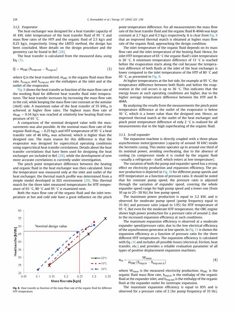
Fig. 8 shows the heat transfer as function of themass flow rate ofthe working fluid for different heat transfer fluid inlet tempera-tures. The heat transfer increases by increasing the mass flow ratein the coil, while keeping themass flow rate constant at the annular(shell) side. A maximum value of the heat transfer of 55 kWth isachieved at higher flow rates. The highest mass flow rate of_mORC ¼ 0.34 kg/s was reached at relatively low heating fluid tem-perature of 65 �C.
A comparison of the nominal designed value with the mea-surements was also possible. At the nominal mass flow rate of theorganic fluid _mORC ¼ 0.25 kg/s and HTF temperature of 95 �C a heattransfer rate of 46 kWth was achieved, which is higher than thedesigned one. The main reason for this difference is that theevaporator was designed for supercritical operating conditionsusing supercritical heat transfer correlations. Details about the heattransfer correlations that have been used for designing the heatexchanger are included in Ref. [28], while the development of newmore accurate correlations is currently under investigation.
The pinch point temperature difference between the heatingand organic fluid in the heat exchanger was then calculated. Sincethe temperature was measured only at the inlet and outlet of theheat exchanger, the thermal match profile was determined from asimple model developed in EES environment [29]. This thermalmatch for the three inlet measured temperatures for HTF temper-ature of 65 �C, 80 �C and 95 �C is examined next.
Both the mass flow rate of the organic fluid and the inlet tem-perature at hot and cold side have a great influence on the pinch
Fig. 8. Heat transfer as function of the mass flow rate of the organic fluid for differentHTF temperature.
point temperature difference. For all measurements the mass flowrate of the heat transfer fluid and the organic fluid R-404Awas keptconstant at 2.7 kg/s and 0.3 kg/s respectively. It is clear from Fig. 8that an improved thermal match is obtained at higher mass flowrate of the organic fluid, approaching the design condition.
The inlet temperature of the organic fluid depends on its massflow rate and the inlet temperature of the heating fluid. Hence, forinlet HTF temperature of 65 �C the organic fluid's inlet temperatureis 26 �C. A minimum temperature difference of 13 �C is reachedbefore the evaporation starts along the coil because the tempera-ture difference of both fluids at the inlet of the heat exchanger islower compared to the inlet temperatures of the HTF of 80 �C and95 �C, as presented in Fig. 9.
At higher temperatures at the hot side, for example at 95 �C, thetemperature difference between both fluids and before the evap-oration in the coil occurs is up to 36 �C. This indicates that theexergy losses at such operating conditions are higher, due to thehigher average temperature difference between the HTF and R-404A.
By analysing the results from the measurements the pinch pointtemperature difference at the outlet of the evaporator is below10 �C, which is a lower value than the designed one. Hence, animproved thermal match at the outlet of the heat exchanger andpinch point temperature difference of only 2 �C is realized for allmeasurements due to the high superheating of the organic fluid.
3.1.3. Scroll expanderThe expansion machine is directly coupled with a three-phase
asynchronous motor/generator (capacity of around 10 kW) insidethe hermetic casing. This motor operates up to around one third ofits nominal power, avoiding overheating, due to the absence ofcooling (in compressor mode it is cooled by the organic fluideusually a refrigerante itself, which enters at low temperature).
The variation of both the pump and expander speed has a strongeffect on electricity production and expansion efficiency. The po-wer production is depicted in Fig. 10 for different pump speeds andHTF temperature as a function of pressure ratio. It should be notedthat for constant pump speed, the pressure ratio is adjustedthrough the variation of expander speed, covering the wholeexpander speed range for high pump speed and a lower one (from10 up to 25e30 Hz) for low pump speed.
The maximum power production is equal to 3.2 kW, and isobserved for moderate pump speed (pump frequency equal to35 Hz) and pressure ratio (equal to 1.95) for HTF temperature of95 �C. But even for the moderate HTF temperature, the ORC engineshows high power production for a pressure ratio of around 2, dueto the increased expansion efficiency at such conditions.
The maximum expansion efficiency is observed at a moderateexpander speed/pressure ratio, due to the low electrical efficiencyof the asynchronous generator at low speeds. In Fig. 11 is shown theexpansion efficiency as a function of pressure ratio for the threedifferent HTF temperatures. The expansion efficiency is calculatedwith Eq. (4) and includes all possible losses (electrical, friction, heattransfer, etc.) and provides a reliable evaluation parameter of alltypes of positive displacement expansion machines.
nex ¼ Wmeas
_mORC�hexp;in � hexp;out;is
� (4)
where Wmeas is the measured electricity production, _mORC is theorganic fluid mass flow rate, hexp,in is the enthalpy of the organicfluid at the expander inlet, and hexp,out is the enthalpy of the organicfluid at the expander outlet for isentropic expansion.
The maximum expansion efficiency is equal to 85% and isobserved for a pressure ratio of 2 (for pump frequency of 35 Hz),
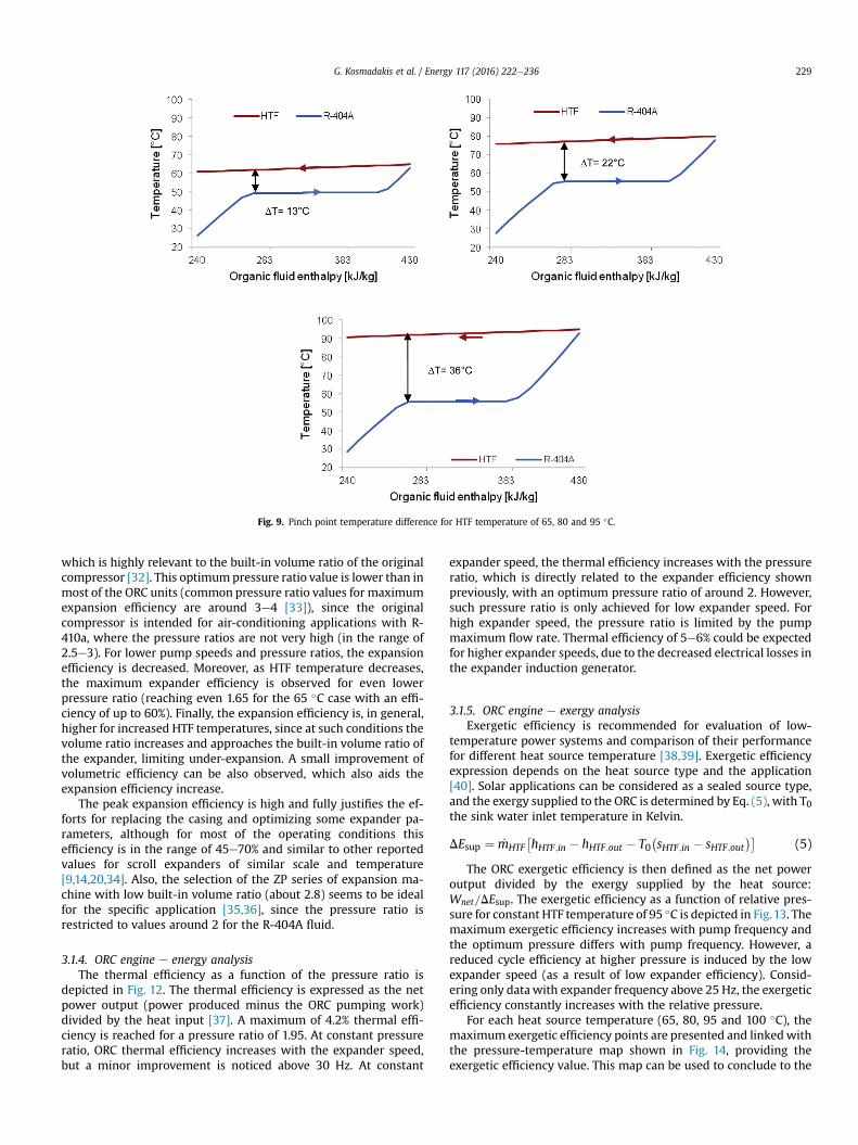
Fig. 9. Pinch point temperature difference for HTF temperature of 65, 80 and 95 �C.
G. Kosmadakis et al. / Energy 117 (2016) 222e236 229
which is highly relevant to the built-in volume ratio of the originalcompressor [32]. This optimumpressure ratio value is lower than inmost of the ORC units (common pressure ratio values for maximumexpansion efficiency are around 3e4 [33]), since the originalcompressor is intended for air-conditioning applications with R-410a, where the pressure ratios are not very high (in the range of2.5e3). For lower pump speeds and pressure ratios, the expansionefficiency is decreased. Moreover, as HTF temperature decreases,the maximum expander efficiency is observed for even lowerpressure ratio (reaching even 1.65 for the 65 �C case with an effi-ciency of up to 60%). Finally, the expansion efficiency is, in general,higher for increased HTF temperatures, since at such conditions thevolume ratio increases and approaches the built-in volume ratio ofthe expander, limiting under-expansion. A small improvement ofvolumetric efficiency can be also observed, which also aids theexpansion efficiency increase.
The peak expansion efficiency is high and fully justifies the ef-forts for replacing the casing and optimizing some expander pa-rameters, although for most of the operating conditions thisefficiency is in the range of 45e70% and similar to other reportedvalues for scroll expanders of similar scale and temperature[9,14,20,34]. Also, the selection of the ZP series of expansion ma-chine with low built-in volume ratio (about 2.8) seems to be idealfor the specific application [35,36], since the pressure ratio isrestricted to values around 2 for the R-404A fluid.
3.1.4. ORC engine e energy analysisThe thermal efficiency as a function of the pressure ratio is
depicted in Fig. 12. The thermal efficiency is expressed as the netpower output (power produced minus the ORC pumping work)divided by the heat input [37]. A maximum of 4.2% thermal effi-ciency is reached for a pressure ratio of 1.95. At constant pressureratio, ORC thermal efficiency increases with the expander speed,but a minor improvement is noticed above 30 Hz. At constant
expander speed, the thermal efficiency increases with the pressureratio, which is directly related to the expander efficiency shownpreviously, with an optimum pressure ratio of around 2. However,such pressure ratio is only achieved for low expander speed. Forhigh expander speed, the pressure ratio is limited by the pumpmaximum flow rate. Thermal efficiency of 5e6% could be expectedfor higher expander speeds, due to the decreased electrical losses inthe expander induction generator.
3.1.5. ORC engine e exergy analysisExergetic efficiency is recommended for evaluation of low-
temperature power systems and comparison of their performancefor different heat source temperature [38,39]. Exergetic efficiencyexpression depends on the heat source type and the application[40]. Solar applications can be considered as a sealed source type,and the exergy supplied to the ORC is determined by Eq. (5), with T0the sink water inlet temperature in Kelvin.
DEsup ¼ _mHTF�hHTF;in � hHTF;out � T0
�sHTF;in � sHTF;out
��(5)
The ORC exergetic efficiency is then defined as the net poweroutput divided by the exergy supplied by the heat source:Wnet=DEsup. The exergetic efficiency as a function of relative pres-sure for constant HTF temperature of 95 �C is depicted in Fig.13. Themaximum exergetic efficiency increases with pump frequency andthe optimum pressure differs with pump frequency. However, areduced cycle efficiency at higher pressure is induced by the lowexpander speed (as a result of low expander efficiency). Consid-ering only datawith expander frequency above 25 Hz, the exergeticefficiency constantly increases with the relative pressure.
For each heat source temperature (65, 80, 95 and 100 �C), themaximum exergetic efficiency points are presented and linkedwiththe pressure-temperature map shown in Fig. 14, providing theexergetic efficiency value. This map can be used to conclude to the
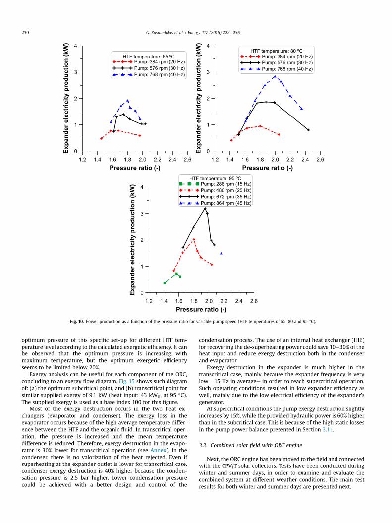
Fig. 10. Power production as a function of the pressure ratio for variable pump speed (HTF temperatures of 65, 80 and 95 �C).
G. Kosmadakis et al. / Energy 117 (2016) 222e236230
optimum pressure of this specific set-up for different HTF tem-perature level according to the calculated exergetic efficiency. It canbe observed that the optimum pressure is increasing withmaximum temperature, but the optimum exergetic efficiencyseems to be limited below 20%.
Exergy analysis can be useful for each component of the ORC,concluding to an exergy flow diagram. Fig. 15 shows such diagramof: (a) the optimum subcritical point, and (b) transcritical point forsimilar supplied exergy of 9.1 kW (heat input: 43 kWth at 95 �C).The supplied exergy is used as a base index 100 for this figure.
Most of the exergy destruction occurs in the two heat ex-changers (evaporator and condenser). The exergy loss in theevaporator occurs because of the high average temperature differ-ence between the HTF and the organic fluid. In transcritical oper-ation, the pressure is increased and the mean temperaturedifference is reduced. Therefore, exergy destruction in the evapo-rator is 30% lower for transcritical operation (see Annex). In thecondenser, there is no valorization of the heat rejected. Even ifsuperheating at the expander outlet is lower for transcritical case,condenser exergy destruction is 40% higher because the conden-sation pressure is 2.5 bar higher. Lower condensation pressurecould be achieved with a better design and control of the
condensation process. The use of an internal heat exchanger (IHE)for recovering the de-superheating power could save 10e30% of theheat input and reduce exergy destruction both in the condenserand evaporator.
Exergy destruction in the expander is much higher in thetranscritical case, mainly because the expander frequency is verylow �15 Hz in averagee in order to reach supercritical operation.Such operating conditions resulted in low expander efficiency aswell, mainly due to the low electrical efficiency of the expander'sgenerator.
At supercritical conditions the pump exergy destruction slightlyincreases by 15%, while the provided hydraulic power is 60% higherthan in the subcritical case. This is because of the high static lossesin the pump power balance presented in Section 3.1.1.
3.2. Combined solar field with ORC engine
Next, the ORC engine has beenmoved to the field and connectedwith the CPV/T solar collectors. Tests have been conducted duringwinter and summer days, in order to examine and evaluate thecombined system at different weather conditions. The main testresults for both winter and summer days are presented next.
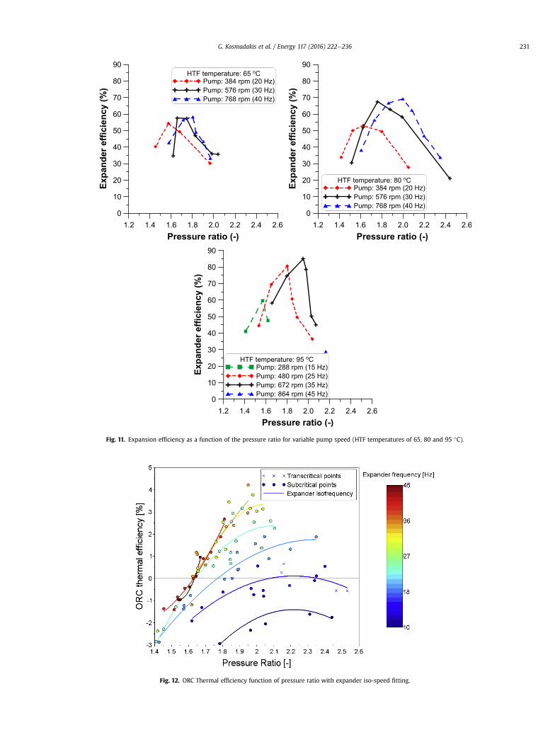
Fig. 11. Expansion efficiency as a function of the pressure ratio for variable pump speed (HTF temperatures of 65, 80 and 95 �C).
Fig. 12. ORC Thermal efficiency function of pressure ratio with expander iso-speed fitting.
G. Kosmadakis et al. / Energy 117 (2016) 222e236 231
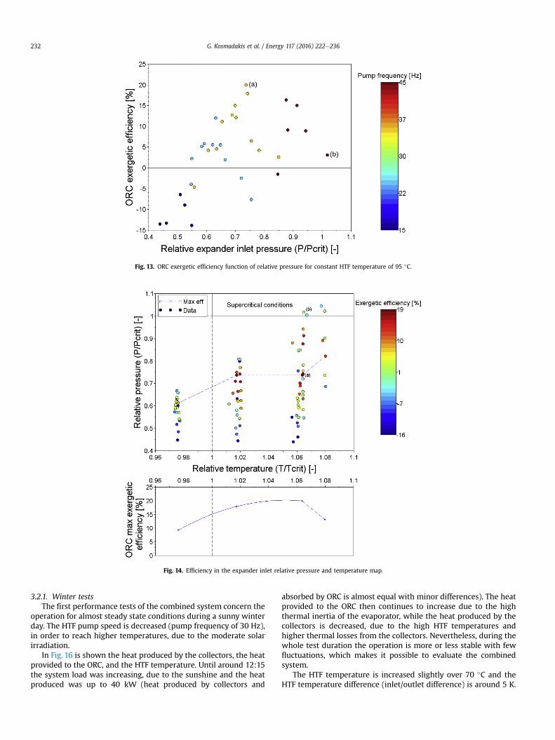
Fig. 13. ORC exergetic efficiency function of relative pressure for constant HTF temperature of 95 �C.
Fig. 14. Efficiency in the expander inlet relative pressure and temperature map.
G. Kosmadakis et al. / Energy 117 (2016) 222e236232
3.2.1. Winter testsThe first performance tests of the combined system concern the
operation for almost steady state conditions during a sunny winterday. The HTF pump speed is decreased (pump frequency of 30 Hz),in order to reach higher temperatures, due to the moderate solarirradiation.
In Fig. 16 is shown the heat produced by the collectors, the heatprovided to the ORC, and the HTF temperature. Until around 12:15the system load was increasing, due to the sunshine and the heatproduced was up to 40 kW (heat produced by collectors and
absorbed by ORC is almost equal with minor differences). The heatprovided to the ORC then continues to increase due to the highthermal inertia of the evaporator, while the heat produced by thecollectors is decreased, due to the high HTF temperatures andhigher thermal losses from the collectors. Nevertheless, during thewhole test duration the operation is more or less stable with fewfluctuations, which makes it possible to evaluate the combinedsystem.
The HTF temperature is increased slightly over 70 �C and theHTF temperature difference (inlet/outlet difference) is around 5 K.
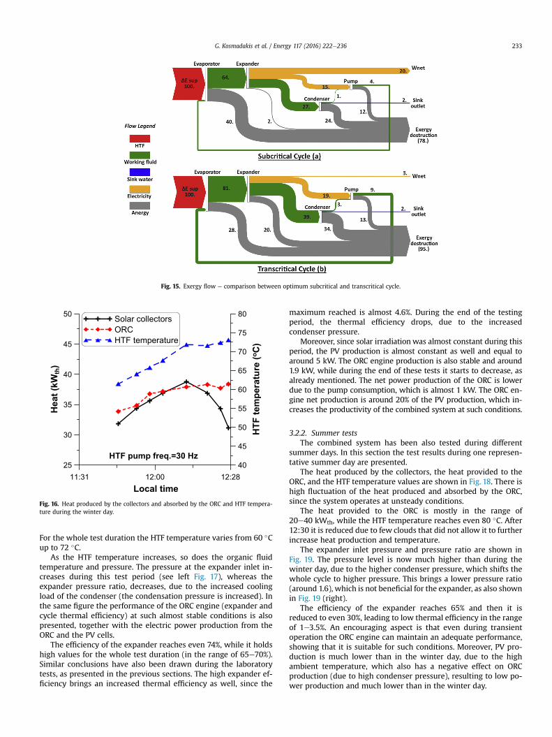
Fig. 15. Exergy flow e comparison between optimum subcritical and transcritical cycle.
Fig. 16. Heat produced by the collectors and absorbed by the ORC and HTF tempera-ture during the winter day.
G. Kosmadakis et al. / Energy 117 (2016) 222e236 233
For the whole test duration the HTF temperature varies from 60 �Cup to 72 �C.
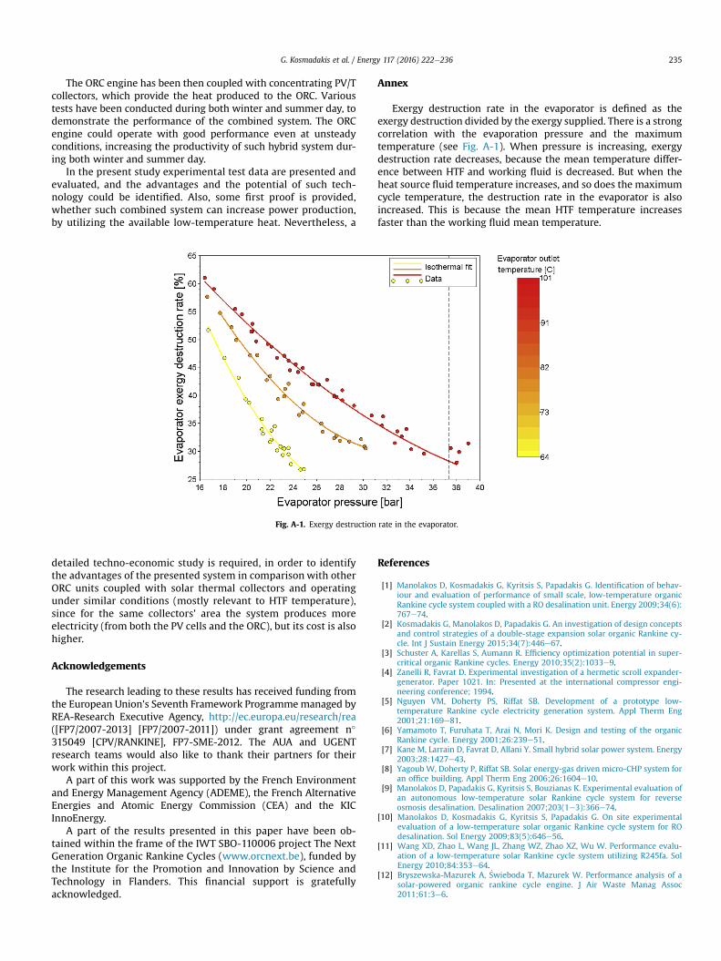
As the HTF temperature increases, so does the organic fluidtemperature and pressure. The pressure at the expander inlet in-creases during this test period (see left Fig. 17), whereas theexpander pressure ratio, decreases, due to the increased coolingload of the condenser (the condensation pressure is increased). Inthe same figure the performance of the ORC engine (expander andcycle thermal efficiency) at such almost stable conditions is alsopresented, together with the electric power production from theORC and the PV cells.
The efficiency of the expander reaches even 74%, while it holdshigh values for the whole test duration (in the range of 65e70%).Similar conclusions have also been drawn during the laboratorytests, as presented in the previous sections. The high expander ef-ficiency brings an increased thermal efficiency as well, since the
maximum reached is almost 4.6%. During the end of the testingperiod, the thermal efficiency drops, due to the increasedcondenser pressure.
Moreover, since solar irradiation was almost constant during thisperiod, the PV production is almost constant as well and equal toaround 5 kW. The ORC engine production is also stable and around1.9 kW, while during the end of these tests it starts to decrease, asalready mentioned. The net power production of the ORC is lowerdue to the pump consumption, which is almost 1 kW. The ORC en-gine net production is around 20% of the PV production, which in-creases the productivity of the combined system at such conditions.
3.2.2. Summer testsThe combined system has been also tested during different
summer days. In this section the test results during one represen-tative summer day are presented.
The heat produced by the collectors, the heat provided to theORC, and the HTF temperature values are shown in Fig. 18. There ishigh fluctuation of the heat produced and absorbed by the ORC,since the system operates at unsteady conditions.
The heat provided to the ORC is mostly in the range of20e40 kWth, while the HTF temperature reaches even 80 �C. After12:30 it is reduced due to few clouds that did not allow it to furtherincrease heat production and temperature.
The expander inlet pressure and pressure ratio are shown inFig. 19. The pressure level is now much higher than during thewinter day, due to the higher condenser pressure, which shifts thewhole cycle to higher pressure. This brings a lower pressure ratio(around 1.6), which is not beneficial for the expander, as also shownin Fig. 19 (right).
The efficiency of the expander reaches 65% and then it isreduced to even 30%, leading to low thermal efficiency in the rangeof 1e3.5%. An encouraging aspect is that even during transientoperation the ORC engine can maintain an adequate performance,showing that it is suitable for such conditions. Moreover, PV pro-duction is much lower than in the winter day, due to the highambient temperature, which also has a negative effect on ORCproduction (due to high condenser pressure), resulting to low po-wer production and much lower than in the winter day.
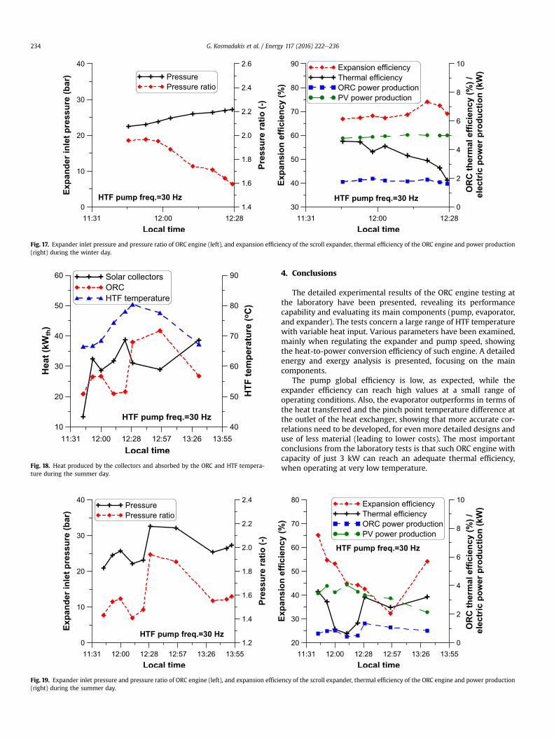
Fig. 17. Expander inlet pressure and pressure ratio of ORC engine (left), and expansion efficiency of the scroll expander, thermal efficiency of the ORC engine and power production(right) during the winter day.
Fig. 18. Heat produced by the collectors and absorbed by the ORC and HTF tempera-ture during the summer day.
Fig. 19. Expander inlet pressure and pressure ratio of ORC engine (left), and expansion effici(right) during the summer day.
G. Kosmadakis et al. / Energy 117 (2016) 222e236234
4. Conclusions
The detailed experimental results of the ORC engine testing atthe laboratory have been presented, revealing its performancecapability and evaluating its main components (pump, evaporator,and expander). The tests concern a large range of HTF temperaturewith variable heat input. Various parameters have been examined,mainly when regulating the expander and pump speed, showingthe heat-to-power conversion efficiency of such engine. A detailedenergy and exergy analysis is presented, focusing on the maincomponents.
The pump global efficiency is low, as expected, while theexpander efficiency can reach high values at a small range ofoperating conditions. Also, the evaporator outperforms in terms ofthe heat transferred and the pinch point temperature difference atthe outlet of the heat exchanger, showing that more accurate cor-relations need to be developed, for even more detailed designs anduse of less material (leading to lower costs). The most importantconclusions from the laboratory tests is that such ORC engine withcapacity of just 3 kW can reach an adequate thermal efficiency,when operating at very low temperature.
ency of the scroll expander, thermal efficiency of the ORC engine and power production
G. Kosmadakis et al. / Energy 117 (2016) 222e236 235
The ORC engine has been then coupled with concentrating PV/Tcollectors, which provide the heat produced to the ORC. Varioustests have been conducted during both winter and summer day, todemonstrate the performance of the combined system. The ORCengine could operate with good performance even at unsteadyconditions, increasing the productivity of such hybrid system dur-ing both winter and summer day.
In the present study experimental test data are presented andevaluated, and the advantages and the potential of such tech-nology could be identified. Also, some first proof is provided,whether such combined system can increase power production,by utilizing the available low-temperature heat. Nevertheless, a
Fig. A-1. Exergy destruction rate in the evaporator.
detailed techno-economic study is required, in order to identifythe advantages of the presented system in comparison with otherORC units coupled with solar thermal collectors and operatingunder similar conditions (mostly relevant to HTF temperature),since for the same collectors' area the system produces moreelectricity (from both the PV cells and the ORC), but its cost is alsohigher.
Acknowledgements
The research leading to these results has received funding fromthe European Union's Seventh Framework Programmemanaged byREA-Research Executive Agency, http://ec.europa.eu/research/rea([FP7/2007-2013] [FP7/2007-2011]) under grant agreement n�
315049 [CPV/RANKINE], FP7-SME-2012. The AUA and UGENTresearch teams would also like to thank their partners for theirwork within this project.
A part of this work was supported by the French Environmentand Energy Management Agency (ADEME), the French AlternativeEnergies and Atomic Energy Commission (CEA) and the KICInnoEnergy.
A part of the results presented in this paper have been ob-tained within the frame of the IWT SBO-110006 project The NextGeneration Organic Rankine Cycles (www.orcnext.be), funded bythe Institute for the Promotion and Innovation by Science andTechnology in Flanders. This financial support is gratefullyacknowledged.
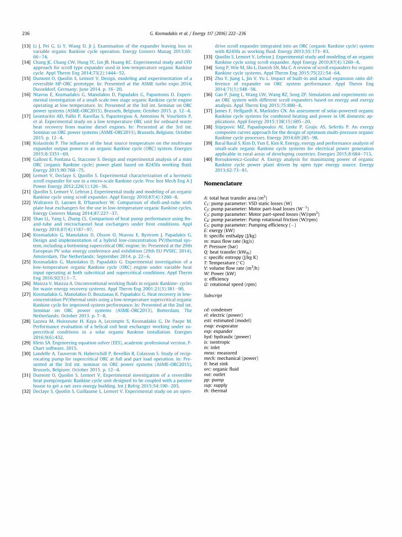
Annex
Exergy destruction rate in the evaporator is defined as theexergy destruction divided by the exergy supplied. There is a strongcorrelation with the evaporation pressure and the maximumtemperature (see Fig. A-1). When pressure is increasing, exergydestruction rate decreases, because the mean temperature differ-ence between HTF and working fluid is decreased. But when theheat source fluid temperature increases, and so does the maximumcycle temperature, the destruction rate in the evaporator is alsoincreased. This is because the mean HTF temperature increasesfaster than the working fluid mean temperature.
References
[1] Manolakos D, Kosmadakis G, Kyritsis S, Papadakis G. Identification of behav-iour and evaluation of performance of small scale, low-temperature organicRankine cycle system coupled with a RO desalination unit. Energy 2009;34(6):767e74.
[2] Kosmadakis G, Manolakos D, Papadakis G. An investigation of design conceptsand control strategies of a double-stage expansion solar organic Rankine cy-cle. Int J Sustain Energy 2015;34(7):446e67.
[3] Schuster A, Karellas S, Aumann R. Efficiency optimization potential in super-critical organic Rankine cycles. Energy 2010;35(2):1033e9.
[4] Zanelli R, Favrat D. Experimental investigation of a hermetic scroll expander-generator. Paper 1021. In: Presented at the international compressor engi-neering conference; 1994.
[5] Nguyen VM, Doherty PS, Riffat SB. Development of a prototype low-temperature Rankine cycle electricity generation system. Appl Therm Eng2001;21:169e81.
[6] Yamamoto T, Furuhata T, Arai N, Mori K. Design and testing of the organicRankine cycle. Energy 2001;26:239e51.
[7] Kane M, Larrain D, Favrat D, Allani Y. Small hybrid solar power system. Energy2003;28:1427e43.
[8] Yagoub W, Doherty P, Riffat SB. Solar energy-gas driven micro-CHP system foran office building. Appl Therm Eng 2006;26:1604e10.
[9] Manolakos D, Papadakis G, Kyritsis S, Bouzianas K. Experimental evaluation ofan autonomous low-temperature solar Rankine cycle system for reverseosmosis desalination. Desalination 2007;203(1e3):366e74.
[10] Manolakos D, Kosmadakis G, Kyritsis S, Papadakis G. On site experimentalevaluation of a low-temperature solar organic Rankine cycle system for ROdesalination. Sol Energy 2009;83(5):646e56.
[11] Wang XD, Zhao L, Wang JL, Zhang WZ, Zhao XZ, Wu W. Performance evalu-ation of a low-temperature solar Rankine cycle system utilizing R245fa. SolEnergy 2010;84:353e64.
[12] Bryszewska-Mazurek A, �Swieboda T, Mazurek W. Performance analysis of asolar-powered organic rankine cycle engine. J Air Waste Manag Assoc2011;61:3e6.
G. Kosmadakis et al. / Energy 117 (2016) 222e236236
[13] Li J, Pei G, Li Y, Wang D, Ji J. Examination of the expander leaving loss invariable organic Rankine cycle operation. Energy Convers Manag 2013;65:66e74.
[14] Chang JC, Chang CW, Hung TC, Lin JR, Huang KC. Experimental study and CFDapproach for scroll type expander used in low-temperature organic Rankinecycle. Appl Therm Eng 2014;73(2):1444e52.
[15] Dumont O, Quoilin S, Lemort V. Design, modeling and experimentation of areversible HP-ORC prototype. In: Presented at the ASME turbo expo 2014,Dusseldorf, Germany; June 2014. p. 16e20.
[16] Ntavou E, Kosmadakis G, Manolakos D, Papadakis G, Papantonis D. Experi-mental investigation of a small-scale two stage organic Rankine cycle engineoperating at low temperature. In: Presented at the 3rd int. Seminar on ORCpower systems (ASME-ORC2015), Brussels, Belgium; October 2015. p. 12e4.
[17] Leontaritis AD, Pallis P, Karellas S, Papastergiou A, Antoniou N, Vourliotis P,et al. Experimental study on a low temperature ORC unit for onboard wasteheat recovery from marine diesel engines. In: Presented at the 3rd int.Seminar on ORC power systems (ASME-ORC2015), Brussels, Belgium; October2015. p. 12e4.
[18] Kolasi�nski P. The influence of the heat source temperature on the multivaneexpander output power in an organic Rankine cycle (ORC) system. Energies2015;8:3351e69.
[19] Galloni E, Fontana G, Staccone S. Design and experimental analysis of a miniORC (organic Rankine cycle) power plant based on R245fa working fluid.Energy 2015;90:768e75.
[20] Lemort V, Declaye S, Quoilin S. Experimental characterization of a hermeticscroll expander for use in a micro-scale Rankine cycle. Proc Inst Mech Eng A JPower Energy 2012;226(1):126e36.
[21] Quoilin S, Lemort V, Lebrun J. Experimental study and modeling of an organicRankine cycle using scroll expander. Appl Energy 2010;87(4):1260e8.
[22] Walraven D, Laenen B, D’haeseleer W. Comparison of shell-and-tube withplate heat exchangers for the use in low-temperature organic Rankine cycles.Energy Convers Manag 2014;87:227e37.
[23] Shao LL, Yang L, Zhang CL. Comparison of heat pump performance using fin-and-tube and microchannel heat exchangers under frost conditions. ApplEnergy 2010;87(4):1187e97.
[24] Kosmadakis G, Manolakos D, Olsson O, Ntavou E, Bystrom J, Papadakis G.Design and implementation of a hybrid low-concentration PV/thermal sys-tem, including a bottoming supercritical ORC engine. In: Presented at the 29thEuropean PV solar energy conference and exhibition (29th EU PVSEC, 2014),Amsterdam, The Netherlands; September 2014. p. 22e6.
[25] Kosmadakis G, Manolakos D, Papadakis G. Experimental investigation of alow-temperature organic Rankine cycle (ORC) engine under variable heatinput operating at both subcritical and supercritical conditions. Appl ThermEng 2016;92(5):1e7.
[26] Maizza V, Maizza A. Unconventional working fluids in organic Rankine- cyclesfor waste energy recovery systems. Appl Therm Eng 2001;21(3):381e90.
[27] Kosmadakis G, Manolakos D, Bouzianas K, Papadakis G. Heat recovery in low-concentration PV/thermal units using a low-temperature supercritical organicRankine cycle for improved system performance. In: Presented at the 2nd int.Seminar on ORC power systems (ASME-ORC2013), Rotterdam, TheNetherlands; October 2013. p. 7e8.
[28] Lazova M, Huisseune H, Kaya A, Lecompte S, Kosmadakis G, De Paepe M.Performance evaluation of a helical coil heat exchanger working under su-percritical conditions in a solar organic Rankine installation. Energies2016;9(6):432.
[29] Klein SA. Engineering equation solver (EES), academic professional version, F-Chart software. 2015.
[30] Landelle A, Tauveron N, Haberschill P, Revellin R, Colasson S. Study of recip-rocating pump for supercritical ORC at full and part load operation. In: Pre-sented at the 3rd int. seminar on ORC power systems (ASME-ORC2015),Brussels, Belgium; October 2015. p. 12e4.
[31] Dumont O, Quoilin S, Lemort V. Experimental investigation of a reversibleheat pump/organic Rankine cycle unit designed to be coupled with a passivehouse to get a net zero energy building. Int J Refrig 2015;54:190e203.
[32] Declaye S, Quoilin S, Guillaume L, Lemort V. Experimental study on an open-
drive scroll expander integrated into an ORC (organic Rankine cycle) systemwith R245fa as working fluid. Energy 2013;55:173e83.
[33] Quoilin S, Lemort V, Lebrun J. Experimental study and modeling of an organicRankine cycle using scroll expander. Appl Energy 2010;87(4):1260e8.
[34] Song P, Wie M, Shi L, Danish SN, Ma C. A review of scroll expanders for organicRankine cycle systems. Appl Therm Eng 2015;75(22):54e64.
[35] Zhu Y, Jiang L, Jin V, Yu L. Impact of built-in and actual expansion ratio dif-ference of expander on ORC system performance. Appl Therm Eng2014;71(1):548e58.
[36] Gao P, Jiang L, Wang LW, Wang RZ, Song ZP. Simulation and experiments onan ORC system with different scroll expanders based on energy and exergyanalysis. Appl Therm Eng 2015;75:880e8.
[37] James F, Hellgardt K, Markides CN. An assessment of solar-powered organicRankine cycle systems for combined heating and power in UK domestic ap-plications. Appl Energy 2015;138(15):605e20.
[38] Stijepovic MZ, Papadopoulos AI, Linke P, Grujic AS, Seferlis P. An exergycomposite curves approach for the design of optimum multi-pressure organicRankine cycle processes. Energy 2014;69:285e98.
[39] Baral Baral S, Kim D, Yun E, Kim K. Energy, exergy and performance analysis ofsmall-scale organic Rankine cycle systems for electrical power generationapplicable in rural areas of developing countries. Energies 2015;8:684e713.
[40] Borsukiewicz-Gozdur A. Exergy analysis for maximizing power of organicRankine cycle power plant driven by open type energy source. Energy2013;62:73e81.
Nomenclature
A: total heat transfer area (m2)C1: pump parameter: VSD static losses (W)C2: pump parameter: Motor part-load losses (W�1)C3: pump parameter: Motor part-speed losses (W/rpm2)C4: pump parameter: Pump rotational friction (W/rpm)C5: pump parameter: Pumping efficiency (�)E: exergy (kW)h: specific enthalpy (J/kg)m: mass flow rate (kg/s)P: Pressure (bar)Q: heat transfer (kWth)s: specific entropy (J/kg K)T: Temperature (�C)V: volume flow rate (m3/h)W: Power (kW)h: efficiencyU: rotational speed (rpm)
Subscript
cd: condenserel: electric (power)esti: estimated (model)evap: evaporatorexp: expanderhyd: hydraulic (power)is: isentropicin: inletmeas: measuredmech: mechanical (power)0: heat sinkorc: organic fluidout: outletpp: pumpsup: supplyth: thermal