Embed Size (px)
Citation preview

J. Cent. South Univ. (2018) 25: 866−878 DOI: https://doi.org/10.1007/s11771-018-3790-z
Experimental study on soil improvement with stone columns and granular blankets
Nima MEHRANNIA1, Farzin KALANTARY2, Navid GANJIAN1
1. Department of Civil Engineering, Tehran Science and Research Branch, Islamic Azad University, Tehran, Iran;
2. Department of Civil Engineering, K.N.Toosi University of Technology, Tehran, Iran
© Central South University Press and Springer-Verlag GmbH Germany, part of Springer Nature 2018
Abstract: Stone column is one of the soil stabilizing methods that is used to increase bearing capacity and decrease the settlement of soft soils. Reinforced and unreinforced granular blankets are now being utilized to overcome the problems of soft soils. In this research, the bearing capacity of stone columns, granular blanket, and a combination of both methods in reinforced and unreinforced modes were studied using scaled physical models. Results show that using granular blanket, stone column, and combination of both improves bearing capacity of soft soils. Using geogrid as the reinforcement of granular blankets and geotextile as stone-column encasement increases the efficiency of granular blankets and stone columns significantly. Additionally, in the case of using geotextile around the stone column, the stress concentration ratio of the stone column will increase as well as its rigidity and bearing capacity. Key words: stone column; bearing capacity; geogrid; geotextile; granular blanket; soil improvement Cite this article as: Nima MEHRANNIA, Farzin KALANTARY, Navid GANJIAN. Experimental study on soil improvement with stone columns and granular blankets [J]. Journal of Central South University, 2018, 25(4): 866–878. DOI: https://doi.org/10.1007/s11771-018-3790-z.
1 Introduction
The problems of soft soil in most parts of the world have been one of the major challenges for geotechnical engineers. Stone columns are created by replacing poor soil with sand or a combination of sand and crushed stones to construct a vertically resistant system. The use of the stone columns is useful, cost-effective and environment-friendly method for resolving such issues. In addition, because of high permeability of stone materials, stone columns speed up the consolidation rate in soft soils and are useful in terms of drainage and in decreasing the potential of liquefaction.
The application of the reinforced soil blankets
has been discussed since long time ago. With the advancement of polymeric products like geotextile and geogrid, their engineering properties will be promoted and will perform well as compared to the unreinforced mode. The role of geosynthetic reinforcement of soil in improving the bearing capacity has been investigated by several researchers [1–10].
Early studies regarding stone column were published by researchers such as GREENWOOD [11]; HUGHES et al [12] and MCKENNA et al [13]. In their researches, they reported the positive performance of the stone column in increasing bearing capacity and reducing settlement. VAN IMPE [14] discussed using geosynthetic to increase bearing capacity of stone columns for the first time.
Received date: 2016−12−27; Accepted date: 2017−03−23 Corresponding author: Farzin KALANTARY; Tel: +98–21–88779474-5(EXT.407); E-mail: [email protected]; ORCID:
0000-0001- 6391-5679

J. Cent. South Univ. (2018) 25: 866–878
867
Lateral confining pressure increased using geotextile around stone columns. Geotextile prevents granular materials of stone column from sinking into the soft soil and as a result, bearing capacity increases significantly. The concept of encasing granular columns with geosynthetics to increase their capacity has been acknowledged by numerous researchers [15–25].
Sufficient lateral confinement may not be available in the case of very soft clays having low undrained shear strengths (cu<15 kPa) [26–28]. MURUGESAN et al [29] explored the bearing capacity improvement of the stone column by geosynthetic rings using numerical analysis with finite element method. Their analysis showed that cylindrical reinforcement around the stone column increases its bearing capacity and rigidity and reduces bulging in compare to ordinary stone column. CHEN et al [30] investigated residual settlement calculation of geocell cushion over gravel piles. The geocell cushion was modeled as a thin flexible plate with large deflection. The results show that gravel piles will improve the spring stiffness and reduce settlement with other conditions remaining the same. Therefore, in engineering practice, it is of significance to enhance the spring stiffness of soft soil to reduce the soil settlement.
GHAZAVI et al [31] explored the bearing capacity of geosynthetic-reinforced stone columns. Stone columns were used with 60, 80, and 100 mm diameters and length of five times their diameters reinforced by geotextile surrounding them. NAZARIAFSHAR et al [32] experimentally studied the bearing capacity of vertical encased stone columns (VESC) and horizontal reinforced stone columns (HRSC). The main objective of this research was to study the efficiency of VESC and HRSC under the same conditions. Experimental results show that the bearing capacity of stone columns increases using vertical or horizontal reinforcing material. Moreover, the bearing capacity of reinforced stone columns increases by increasing the strength of reinforcement in both VESC and HRSC. Also bulging failure mechanism governed in all tests and lateral bulging decreases using geotextiles and increasing strength of reinforcement.
The consolidation theories for soft ground improved by columns are developed on the basis of those for sand-drained well foundation. Significant studies have been made in developing the consolidation theory for soft ground improved by granular column, such as stone column and sand column. GONG et al [33] derived a simplified method for predicating consolidation settlement of soft ground improved by floating soil−cement column.
Problems of similarity between reduced-scale models and equivalent field-scale prototypes lead to uncertainty about whether the behavior and mechanisms observed in reduced scale models typical of the field-scale prototype. IAI [34], WESTINE et al [35], DASH et al [36] and HONG et al [37] reported similarity between reduced-scale models and equivalent field-scale prototypes.
Most of the previous research was done on stone columns without granular blanket and simultaneous application of stone column and granular blanket was rarely studied. Also, in most of these studies, stone columns are settled on stiff beds (unfloating column) and they rarely studied the effect of floating stone columns. Moreover, in most projects, the length of stone column is not so long to reach stone surface and most of the stone columns are floating types. In this study, using large-scale laboratory tests, the bearing capacity of floating stone columns with granular blanket was examined in two type of reinforced and unreinforced mode. To do so, stone columns with 60 mm diameter and 200 mm length were constructed using geotextile to reinforce them. The thicknesses of granular blankets are 40 mm and 75 mm and geogrid was used for reinforcing them. 2 Experimental setup and test procedure
Figure 1 illustrates schematic diagram of experimental setup with or without blanket. A large test chamber (120 cm×120 cm×90 cm) was used for the experimental studies. The dimensions of the stone columns were 60 mm in diameter and 200 mm in length.
MAYERHOF et al [38] observed that the failure zone below a rigid pile extends over a depth of approximately 2 times its diameter. Because the

J. Cent. South Univ. (2018) 25: 866–878
868
Figure 1 Schematic diagram of test setup without
blanket (a) and with blanket (b)
stone columns are flexible, this depth would be less. SELIG et al [39] and CHUMMER [40] indicated that the failure wedge in the foundation bed extends over a distance of approximately 2–2.5 times the footing width (D), away from its center. In the present study, the diameter of the loading plate is 20 cm and the distance of the chamber walls from center of the footing is approximately 3D, so the failure wedge does not interfere with the chamber walls. Also, the diameter of loading plate (D= 200 mm) was approximately in 1:10 scale representation of prototype foundation of 2000 mm in diameter. The dimensions of stone columns are 60 mm in diameter and 200 mm in length were considered constant in all tests. To prevent deformation in the boundary of the experimental box, the walls were made stiff on all sides. Soft clay
construction was done by a unit weight-control method, and the box walls were graded in 5 cm intervals. The soft clay layers were filled into the box in layers with a 5 cm thickness, and then compacted. The loading systems consist of the loading frame, the server motor, the loading plate, and the data-acquisition system. The loading was applied based on the displacement-control method at a rate of 1 mm/min. The steel loading plate with a diameter of 20 cm and a thickness of 3 cm was used, and it was placed in the center of the stone column. The data-acquisition systems included the computer, data logger, and four sensors. Two linear variable differential transformers (LVDT) were placed on the loading plate to record the displacement data. They measured any probable rotation occurring on the loading plate. Figure 1 shows a schematic diagram of an experimental setup with or without a blanket. The load cell employed was class S with a capacity of 3000 kg for measuring total force on a loading plate and a miniature load cell with a capacity of 500 kg mounted on top of the stone column for measuring stone column bearing force. Figure 2(a) illustrates the loading frame and server motor. Figure 2(b) shows the loading plate and sensors for experimental tests.
Figure 2 Testing setup: (a) Loading frame and large test
box; (b) Loading plate and data acquisition instruments
All tests were carried out until the full
penetration of 50 mm displacement was achieved (25% of diameter of loading plate). In total, 12 tests were performed, and it is noted that some repeated tests were performed to ensure that the results are repeatable and consistent. Table 1 summarizes the experimental test details.

J. Cent. South Univ. (2018) 25: 866–878
869
Table 1 Summary of experimental program
Test No. Test name Test property
1 Clay
2 OSC Ordinary stone column
3 ESC Encased stone column
4 URB40 Unreinforced blanket with 40 mm thickness
5 URB75 Unreinforced blanket with 75 mm thickness
6 1RB40 One layered reinforced blanket
with 40 mm thickness
7 1RB75 One layered reinforced blanket
with 75 mm thickness
8 2RB75 Two layered reinforced blanket
with 75 mm thickness
9 OSC+URB40 Ordinary stone column+unreinforced
blanket with 40 mm thickness
10 ESC+URB40 Encased stone column+unreinforced
blanket with 40 mm thickness
11 OSC+1RB75 Ordinary stone column+one layered
reinforced blanket with 75 mm thickness
12 ESC+1RB75 Encased stone column+one layered
reinforced blanket with 75 mm thickness
3 Materials properties 3.1 Clay and stone materials
Clay beds were prepared using a locally available soil. Table 2 represents its properties in experimental tests. To determine the moisture content corresponding to 15 kPa of the undrained shear strength of the clay, a series of unconfined compressive strength tests were carried out on a cylindrical specimen with a diameter of 38 mm and a height of 90 mm. These tests were carried out on different water-content percentages according to ASTM D2166. Figure 3 illustrates the undrained shear strength versus various water-content in clay. It can be seen that the required water-content is 26% to reach an undrained shear strength of 15 kPa. It must be noted that to ensure the water-content required for achieving an undrained shear strength of 15 kPa, an unconsolidated undrained triaxial test was also performed on a cylindrical sample with a diameter of 100 mm in 26% water content, based on ASTM D2850. The triaxial test results are in a good agreement with unconfined compression test results.
Table 3 describes the properties of stone material, and Figure 4 shows the particle-size distribution for stone columns and clay materials.
Table 2 Properties of clay
Parameter Value
Specific gravity 2.7
Liquid limit/% 31
Plastic limit/% 18
Plastic index 13
Optimum moisture content/% 17
Maximum dry unit weight/(kN·m–3) 16.5
Bulk unit weight at 26% water content/(kN·m–3) 19.5
Undrained shear strength at 26% water content/kPa 15
USCS classification symbol CL
Figure 3 Variation of undrained shear strength of clay
with water content
Table 3 Properties of stone column material
Prameter Value
Specific gravity 2.6
Maximum dry unit weight/(kN·m–3) 16.7
Minimum dry unit weight(kN·m–3) 14.5
Bulk unit weight for test at 71% relative density/(kN·m–3)
16
Internal friction angle at 71% relative density/(°) 47
Uniformity coefficient 2
Curvature coefficient 1.23
Unified system classification GP
Crushed stone materials ranging from 2 mm to 10 mm were used for the stone column materials. D10, D50 and D90 are 3.4, 6.4, and 9.1 mm, respectively. The dry unit weight of 16 kN/m3 was chosen as the unit weight of the granular material for the stone column and blanket. The selected unit weight corresponds to relative density of 71%. The triaxial test with a diameter of 100 mm was conducted to determine the internal friction angle of the granular materials.

J. Cent. South Univ. (2018) 25: 866–878
870
Figure 4 Particle size distribution for granular and clay
materials
The ratio of the average aggregate size
(D50=6.4 mm) to the diameter of the stone columns (D=60 mm) was approximately a 1:10 scale representation of the prototype stone columns of 600 mm diameter and an average aggregate size of 64 mm. Also, the size of the crushed stone was chosen in accordance with the guidelines suggested by NAYAK [41] and FATTAH et al [42], in which the particle size is approximately 1/6 to 1/7 of the diameter of the stone columns. A value of 1/6 for this ratio was considered adequate, based on the works of FOX [43], STOEBER [44], and MOHAPATRA et al [28], in which a ratio of approximately 6 for the triaxial specimen diameter to maximum particle size was found to be satisfactory for granular material. In this research, the diameter of the stone column is 60 mm, so the maximum size of the stone column material is limited to 10 mm. 3.2 Reinforcement properties
The type of reinforcement is determined with respect to the effect of the model scale. Based on the scale effect rules presented by IAI [34] and discussed by DASH et al [36], GHAZAVI et al [31], and HONG et al [37], the relationship between the prototype and model reinforcement stiffness can be calculated using Eq. (1).
2
mp JJ (1) where Jp is prototype-reinforcement stiffness; Jm is model-reinforcement stiffness; 1/λ is the model scale that in this research λ is 10.
In most projects, geotextile stiffness varies between 50 and 2000 kN/m, and geogrid stiffness is
below 4000 kN/m (Huesker & Tencate [37]). Because the scale parameter λ=1/10 was used in this research, the reinforcement stiffness was selected and applied based on the scale effect. Table 4 describes the properties of reinforcements. Table 4 Properties of geogrid and geotextile
Parameter Geotextile Geogrid
Yarn material Polypropylene Polypropylene
Ultimate tensile strength/(kN·m–1)
9 6.5
Strain at ultimate strength/%
55 38.6
Stiffness at ultimate strain,J/(kN·m–1)
16.36 16.84
Thickness/mm 1 2
Mass/(g·m–2) 140 —
Mesh aperture/mm — 25
4 Construction of physical models 4.1 Preparation of clay bed
Clay was sieved with a 1 cm aperture to separate any impurities and lumps. Two layers of thick nylon were used to prevent any water content reduction inside the preparation boxes. Primary clay water content was accurately measured to estimate the water required to reach a water content of 26%. The clay was placed in the preparation box in the form of 1 cm layers. The water required to reach water content of 26% was steadily spattered over each layer using a special sprinkler. Then, the sample was covered by nylon and left for one week to reach equal water content. To ensure a soil water content of 26%, a water-content test was performed on soil samples from various parts of soil boxes. To control the thickness of each layer, the main box wall was graded in 5 cm intervals so soft clay samples could be constructed in 5 cm layers using the unit-weight-control method. Before carrying out any tests, the main box walls were coated by a thin layer of grease to reduce any friction between the clay and the walls. To reach a unit weight of 19.5 kN/m3, clay was weighed, and it was placed into the main box in the form of 5 cm layers. The layers were compacted using a special hammer (150 mm×150 mm and w=10 kg). Five steel bars with a diameter of 10 mm and a length of 20 mm were placed under the special hammer for kneading each clay layer. This helped to reduce leftover air voids in the test bed and to connect clay layers to

J. Cent. South Univ. (2018) 25: 866–878
871
one another. Each soil layer was compacted to reach 50 cm in height, and the final soft clay surface was leveled and trimmed to have a proper surface without any cavities. This construction method was replicated for all the experimental tests. Throughout the course of the experiments, the water content was measured to ensure the desired percentage of water. The results showed that the water-content percentage variations were below 1% in all tests. To further reassure the undrained strength of the soft clay sample after each test, an unconfined compression test was carried out on samples. In all the unconfined compression tests, the results approved the presence of the undrained shear strength of 15 kPa, and the water content was 26%. 4.2 Construction of reinforced and unreinforced
stone columns A floating stone column with a diameter of
60 mm and a length of 200 mm was used in this study. Stone columns were reinforced using geotextile. All stone columns were constructed with the replacement method in the center of the main large box. To construct the stone columns, a hollow steel open-ended pipe without any seam was used with a diameter of 60 mm and a thickness of 2 mm. In all tests, the internal and external areas of the steel pipe were coated by oil to reduce the surrounding soil manipulation and also to place the soil inside it easily. The hollow pipe was then vertically settled on the clay and pushed into it. During this procedure, the vertical state was carefully controlled by a special level. After reaching 200 mm in depth, the soil inside was discharged using a steel spiral auger. The diameter of the auger was smaller than the inner diameter of
the pipe. In each step, soil with a maximum thickness of 50 mm was removed. After that, the pipe was pulled out slowly without any deviation from its vertical state. The stone column materials were then weighted and placed into the hole and compacted to reach the thickness of 0.5D (with D being the diameter of the stone column). In all tests, the unit weight of the stone column materials was 16 kN/m3. To achieve a uniform density, a steel circular tamper with a weight of 2 kg and a diameter of 20 mm was employed. Figure 5(a) illustrates an unreinforced stone column, and Figure 5(b) shows a reinforced stone column, respectively.
To construct a reinforced stone column, nonwoven polypropylene geotextile was first cut into a rectangular form. It was constructed in cylindrical form with thermal glue made of polypropylene. The extent of geotextile overlap on the seam was 1.5 cm. It should be mentioned that tension tests confirmed the adequacy of this type of joint. It indicated that the presence of a seam coated by the thermal glue to make a geotextile encasement had no adverse effect on the geotextile strength (Figure 6). After construction, the steel pipe was encased by geotextile reinforcement, and the reinforcement was pushed into the soft clay with the pipe. To prevent the displacement of the reinforcement, an appropriate joint was created at the bottom of the column. Granular materials were then placed and compacted as previously described.
4.3 Constructing reinforced and unreinforced
granular blankets Stone column materials were used to construct
Figure 5 Plan view of unreinforced stone column (a) and reinforced stone column (b)

J. Cent. South Univ. (2018) 25: 866–878
872
Figure 6 Tensile load–strain behavior of geotextile
samples with and without seam
the granular blankets. The blanket thicknesses were 40 mm and 75 mm in which the ratio of the granular blanket depth and the footing width is 0.2 and 0.37. BAI et al [45] considered this ratio equal to 0.2. Granular materials were weighed to reach a unit weight of 16 kN/m3 and the half thickness of the blankets. They were then placed over the soft clay and compacted using a cylindrical hammer (10 mm in diameter) made of polypropylene to reach the specified thickness. In the previous studies, an optimum length was shown for the reinforcements [46–49]. They concluded that lengths over the optimum value do not have a positive effect to increase bearing capacity. This length is about 2 to 8 times the diameter or the width of the loading plate. Apparently, the optimum length of the reinforcements depends on such conditions as the number of reinforcing layers, the type of soil, and the soil density. For instance, MOSALLANEZHAD et al [50] demonstrated that, as the number of the reinforcing layers increases, its optimum length will also increase. In the present research, geogrids in the form of squares with lengths of 3 times the diameter of the loading plate were used to reinforce the granular blanket. They were placed in the middle of the blanket layer. 5 Results and discussion 5.1 Load–settlement behavior of samples
In this part, all the bearing capacity of the tests was measured in 50 mm settlement. The settlement reported is the average of the readings taken at both ends of the loading plate (two LVDTs placed on the loading plate) . Figures 7, 8 and 9 show the
Figure 7 Load–settlement variation of reinforced and
unreinforced stone columns
Figure 8 Load–settlement variation of reinforced and
unreinforced blankets
Figure 9 Load–settlement variation of combination of
granular blankets and stone columns
load–settlement curves of a singular stone column, a singular granular blanket, and a combination of granular blankets and stone columns, respectively. The application of a geogrid in reinforcing the granular blanket and geotextile as the encasement of the stone column improved their performance. Also, the simultaneous use of the stone column and
J. Cent. South Univ. (2018) 25: 866–878
873
the granular blanket considerably increased the bearing capacity of soft soils and had advantages such as horizontal and vertical drainages.
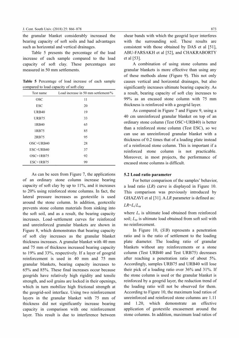
Table 5 presents the percentage of the load increase of each sample compared to the load capacity of soft clay. These percentages are measured in 50 mm settlements.
Table 5 Percentage of load increase of each sample
compared to load capacity of soft clay
Test name Load increase in 50 mm settlement/%
OSC 11
ESC 20
URB40 19
URB75 33
1RB40 65
1RB75 85
2RB75 95
OSC+URB40 28
ESC+URB40 37
OSC+1RB75 92
ESC+1RB75 99
As can be seen from Figure 7, the applications
of an ordinary stone column increase bearing capacity of soft clay by up to 11%, and it increases to 20% using reinforced stone columns. In fact, the lateral pressure increases as geotextile is used around the stone column. In addition, geotextile prevents stone column materials from sinking into the soft soil, and as a result, the bearing capacity increases. Load–settlement curves for reinforced and unreinforced granular blankets are shown in Figure 8, which demonstrates that bearing capacity of soft clay increases as the granular blanket thickness increases. A granular blanket with 40 mm and 75 mm of thickness increased bearing capacity to 19% and 33%, respectively. If a layer of geogrid reinforcement is used in 40 mm and 75 mm granular blankets, bearing capacity increases to 65% and 85%. These final increases occur because geogrids have relatively high rigidity and tensile strength, and soil grains are locked in their openings, which in turn mobilize high frictional strength at the geogrid-soil interface. Using two reinforcement layers in the granular blanket with 75 mm of thickness did not significantly increase bearing capacity in comparison with one reinforcement layer. This result is due to interference between
shear bands with which the geogrid layer interferes with the surrounding soil. These results are consistent with those obtained by DAS et al [51], ABU-FARSAKH et al [52], and CHAKRABORTY et al [53].
A combination of using stone columns and granular blankets is more effective than using any of these methods alone (Figure 9). This not only causes vertical and horizontal drainages, but also significantly increases ultimate bearing capacity. As a result, bearing capacity of soft clay increases to 99% as an encased stone column with 75 mm thickness is reinforced with a geogrid layer.
As compared in Figure 7 and Figure 9, using a 40 cm unreinforced granular blanket on top of an ordinary stone column (Test OSC+URB40) is better than a reinforced stone column (Test ESC), so we can use an unreinforced granular blanket with a thickness of 0.2 times that of a loading plate instead of a reinforced stone column. This is important if a reinforced stone column is not practicable. Moreover, in most projects, the performance of encased stone columns is difficult. 5.2 Load ratio parameter
For better comparison of the samples’ behavior, a load ratio (LR) curve is displayed in Figure 10. This comparison was previously introduced by GHAZAVI et al [31]. A LR parameter is defined as:
LR=Lr/Lnr where Lr is ultimate load obtained from reinforced soil; Lnr is ultimate load obtained from soft soil with no reinforcement.
In Figure 10, (S/B) represents a penetration ratio and is the ratio of settlement to the loading plate diameter. The loading ratio of granular blankets without any reinforcements or a stone column (Test URB40 and Test URB75) decreases after reaching a penetration ratio of about 5%. Accordingly, samples URB75 and URB40 will lose their pick of a loading ratio over 36% and 31%. If the stone column is used or the granular blanket is reinforced by a geogrid layer, the reduction trend of the loading ratio will not be observed for them. According to Figure 10, the maximum load ratios of unreinforced and reinforced stone columns are 1.11 and 1.20, which demonstrate an effective application of geotextile encasement around the stone columns. In addition, maximum load ratios of

J. Cent. South Univ. (2018) 25: 866–878
874
40 mm and 75 mm thick unreinforced granular blankets were 1.27 and 1.50. The maximum load ratios in one layer reinforced by 40 mm and 75 mm granular blankets were 1.64 and 1.83, which show effective application of a geogrid in granular blankets. The load ratio of two reinforced layers in 75 mm granular blanket increased to 1.94 and did not significantly increase bearing capacity in comparison with one reinforcement layer. According to Table 6, using a 40 mm granular blanket over an ordinary stone column increased the maximum LR from 1.11 to 1.28 (a 15% increase), and using a 40 mm granular blanket over an encased stone column increased the maximum LR from 1.20 to 1.38 (a 15% increase). Using a 75 mm reinforced granular blanket over an ordinary stone column increased the maximum LR from 1.11 to 1.92 (a 73% increase), and over an encased stone column, it increased the maximum LR from 1.20 to
Figure 10 Verification of load ratio versus penetration
ratio for samples Table 6 Maximum load ratio in tests
Test name Max load ratio
OSC 1.11
ESC 1.20
UB40 1.27
UB75 1.50
1RB40 1.64
1RB75 1.83
2RB75 1.94
OSC-URB40 1.28
ESC-URB40 1.38
OSC-1RB75 1.92
ESC-1RB75 2.01
2.01 (a 67% increase). Using a 75 mm reinforced granular blanket over an ordinary or reinforced stone column significantly improved the efficiency of a combination of stone columns and granular blankets. In addition, because of the high permeability of stone materials, stone columns and blankets speed up the consolidation rate in soft soils and are useful in terms of drainage and in decreasing the potential of liquefaction. 5.3 Stress concentration ratio
The external load is distributed between the stone column and its surrounding soil. Since the column stabaleiffness is greater than the soft soil, the stresses on the columns are greater than the surrounding soft soil. In the literature, the ratio of the stress in stone columns (Sstone) to the stress in soft clay surrounding soil (Sclay) is defined as the stress concentration ratio (SCR) and is denoted by n. MURUGESAN et al [54], FATTAH et al [42], GHAZAVI et al [31], and DEB et al [55] previously used the SCR to investigate the bearing capacity of stone columns.
The SCR is defined as:
clay
stone
S
Sn
In this study, a hole is located at the back and
the center of the loading plate to place a miniature load cell on the stone column and measure the load on the stone column, which was used to measure the SCR. The loading capacity of the stone column at each settlement can be measured using the miniature load cell. The load on the soil around the stone columns was measured by the difference between the main load and the load on the stone columns at each settlement.
As shown in Figure 11, the SCR of the stone column is increased by using geotextile encasement. The maximum value of n is 2.67 for an unreinforced stone column, and it occurs at S/B=1. Then the SCR descends, and after a 25% reduction, it reaches 2. In a reinforced stone column, the maximum of this ratio is 3.5. It occurs at S/B=11, and after a 12% reduction, it reaches 3.05. In reinforced stone columns, due to the increased stiffness of stone columns that corresponds to an increase in soil lateral pressure, bulging is reduced, and bearing capacity is increased.

J. Cent. South Univ. (2018) 25: 866–878
875
Figure 11 Verification of stress concentration ratio
versus penetration ratio for samples
5.4 Deformations and failure mode
Bulging mechanism usually occurs depending on whether the tip of the column is floating in soft soil or resting on a firm bearing layer. Also the failure of stone columns depends on the ratio of length to diameter of stone columns. As discussed by previous researchers, in a stone column, with a length to diameter ratio over 5 (long stone column), failure occurs due to the bulging. This bulging occurred at a distance about 1.5 to 3 times the stone column diameter from the top of the stone column [31, 37, 56–58]. In a floating stone column, with a length to diameter ratio less than 3 (short stone column), the ultimate bearing capacity is controlled by punching mechanism. ABOSHI et al [59] studied this type of failure. General shear occurs in short stone columns that rely on a hard bed. WONG [60], MADHAV et al [61], and BARKSDALE et al [56] studied this type of failure.
In this research, the deformations and failure mode of floating stone columns were examined for two reinforced and unreinforced stone columns. Also, the effect of the presence of a granular blanket over the stone column on its deformation and failure mode was studied. After carrying out experimental tests, the stone column deformation and failure mode were accurately examined and measured by filling paste of plaster of pairs in stone column and dented place of loading plate. In unreinforced stone columns, the failure mode was punching with little bulging. This bulging was seen at a depth of the stone column diameter (D) from the column head.
In the case of a reinforced stone column, no bulging was seen, and a punching mode happened.
In reinforced and unreinforced stone columns placed under the granular blanket, only a punching mode was observed, and bulging was not seen in any stone columns. In all tests, stone columns deformations were symmetrical, and no lateral deformation was seen. 6 Conclusions
Large-scale experimental tests were carried out on a singular stone column, a singular granular blanket, and combination of stone column and granular blanket. Granular blanket was examined in two thickness including 40 mm and 75 mm. The stone column was reinforced by geotextile and the granular blanket by geogrid. Based on the results of this study, there are suggestions for designers and it can be concluded that:
1) Using granular blanket, stone column, and a combination of both increase ultimate bearing capacity and as a result simultaneous use of the stone column and the granular blanket considerably increased the bearing capacity of soft soils and have advantages such as horizontal and vertical drainage.
2) Using geogrid as a granular blanket reinforcement and geotextile as the stone column, encasement leads to a better efficiency of granular blanket and stone column and increases the rigidity of the reinforced soil. Geogrids have relatively high rigidity and tensile strength, and soil grains are locked in their openings, which in turn mobilize high frictional strength at the geogrid-soil interface. In addition, geotextile prevents stone column materials from sinking into the soft soil, and as a result, the bearing capacity increases.
3) We can use an unreinforced granular blanket with a thickness of 0.2 times that of a loading plate instead of a reinforced stone column. This is important if a reinforced stone column is not practicable. Moreover, in most projects, the performance of encased stone columns is difficult.
4) If the stone column is used or the granular blanket is reinforced by a geogrid layer, the reduction trend of the loading ratio will not be observed for them. Using a 75 mm reinforced granular blanket over an ordinary or reinforced stone column significantly increased maximum load ratio and improved the efficiency of a combination of stone columns and granular blankets.
5) By using geotextile encasement in stone

J. Cent. South Univ. (2018) 25: 866–878
876
column stress concentration ratio, bearing capacity and the stiffness of stone column increases.
6) In unreinforced stone columns, the failure mode was punching with little bulging. This bulging was seen at a depth of the stone column diameter (D) from the column head. In the case of a reinforced stone column, no bulging was seen, and a punching mode happened. In reinforced and unreinforced stone columns placed under the granular blanket, only a punching mode was observed, and bulging was not seen in any stone columns. In all tests, stone columns deformations were symmetrical, and no lateral deformation was seen. Acknowledgements
The authors would like to thank Dr. J. NAZARIAFSHAR for fruitful discussions and valuable advices on the use of theoretical and experimental set up. The authors acknowledge the help rendered by Mr. A. SEDAGHAT at various stages during this research.
References [1] AKIMUSURU J O, AKINBOLADE J A. Stability of loaded
footing on reinforced soil [J]. Journal of Geotechnical and
Geoenvironmental Engineering, ASCE, 1981, 107(6):
819–827.
[2] GUIDO V, BIESIADECKI G, SULLIVAN M. Bearing
capacity of a geotextile reinforced foundation [C]//
Proceedings of the 11th International Conference on Soil
Mechanics and Foundation Engineering. 1985: 1777–1780.
[3] YETIMOGLU T, WU J T, SAGLAMER A. Bearing capacity
of rectangular footings on geogrid-reinforced sand [J].
Journal of Geotechnical Engineering, 1994, 120: 2083–2099.
[4] HATAF N, BAZIAR A. Use of tire shreds for bearing
capacity improvement of shallow footing on sand [C]//
Proceedings of the 3rd Int Conf on Ground Improvement
Techniques. 2000: 189–194.
[5] ABDRABBO F M, GAAVER K E, ELWAKIL A Z. Behavior
of square footing on single reinforced soil [C]// Procceding
of Geo-Support, ASCE. Orlando, Florida, 2004: 1015–1026
[6] PATRA C, DAS B, ATALAR C. Bearing capacity of
embedded strip foundation on geogrid-reinforced sand [J].
Geotextiles and Geomembranes, 2005, 23: 454–462.
[7] SITHARAM T, SIREESH S. Behavior of embedded footings
supported on geogrid cell reinforced foundation beds [J].
Geotechnical Testing Journal, 2005, 28(5): 1–12.
[8] ZIDAN A. Numerical study of behavior of circular footing
on geogrid-reinforced sand under static and dynamic loading
[J]. Geotechnical and Geological Engineering, 2012, 30:
499–510.
[9] KUMAR A, WALIA B. Bearing capacity of square footings
on reinforced layered soil [J]. Geotechnical and Geological
Engineering, 2006, 24: 1001–1008.
[10] ADAMS M T, COLLIN J G. Large model spread footing
load tests on geosynthetic reinforced soil foundations [J].
Journal of Geotechnical and Geoenvironmental Engineering,
1997, 123: 66–72.
[11] GREENWOOD D A. Mechanical improvement of soils
below ground surface [C]// Proceedings of Ground
Improvement Conference. Institute of Civil Engineering,
1970: 9–29.
[12] HUGHES J M O, WITHERS N J. Reinforcing of soft
cohesive soils with stone columns [J]. Ground Engineering,
1974, 7(3): 42–49.
[13] MCKENNA J, EYRE W, WOLSTENHOLME D.
Performance of an embankment supported by stone columns
in soft ground [J]. Geotechnique, 1975, 25: 51–59.
[14] VAN IMPE W F. Soil improvement techniques and their
evolution [M]. Rotterdam, Netherlands: Balkema, 1989.
[15] MURUGESAN S, RAJAGOPAL K. Shear load tests on
stone columns with and without geosynthetic encasement [J].
Geotechnical Testing Journal, 2009, 32(1): 1–10.
[16] YOO C. Performance of geosynthetic-encased stone columns
in embankment construction: numerical investigation [J].
Journal of Geotechnical and Geoenvironmental Engineering,
2010, 136: 1148–1160.
[17] YOO C, LEE D. Performance of geogrid-encased stone
columns in soft ground: Full-scale load tests [J].
Geosynthetics International, 2012, 19: 480–490.
[18] ZHANG Y, CHAN D, WANG Y. Consolidation of composite
foundation improved by geosynthetic-encased stone columns
[J]. Geotextiles and Geomembranes, 2012, 32: 10–17.
[19] ALMEIDA M, HOSSEINPOUR I, RICCIO M. Performance
of a geosynthetic-encased column (GEC) in soft ground:
Numerical and analytical studies [J]. Geosynthetics
International, 2013, 20: 252–262.
[20] DASH S K, BORA M C. Influence of geosynthetic
encasement on the performance of stone columns floating in
soft clay [J]. Canadian Geotechnical Journal, 2103, 50:
754–765.
[21] ELSAWY M. Behaviour of soft ground improved by
conventional and geogrid-encased stone columns, based on
FEM study [J]. Geosynthetics International, 2013, 20:
276–285.
[22] MAHESHWARI P, CHAUHAN V B. Beams on extensible
geosynthetics and stone-column-improved soil [J].
Proceedings of the Institution of Civil Engineers-Ground
Improvement, 2013, 166: 233–247.
[23] MCCABE B, KAMRAT-PIETRASZEWSKA D, EGAN D.
Ground heave induced by installing stone columns in clay
soils [J]. Proceedings of the Institution of Civil Engineers-
Geotechnical Engineering, 2013, 166: 589–593.
[24] SHAHU J, REDDY Y. Estimating long-term settlement of
floating stone column groups [J]. Canadian Geotechnical
Journal, 2014, 51: 770–781.
[25] ALI K, SHAHU J, SHARMA K. Model tests on single and
groups of stone columns with different geosynthetic
reinforcement arrangement [J]. Geosynthetics International,
2014, 21: 103–118.
[26] RAITHEL M, KEMPFERT H G, KIRCHNER A. Geotextile-

J. Cent. South Univ. (2018) 25: 866–878
877
encased columns (GEC) for foundation of a dike on very soft
soils [C]// Proceedings of the Seventh International
Conference on Geosynthetics. Nice, France, 2002:
1025–1028.
[27] MURUGESAN S, RAJAGOPAL K. Model tests on
geosynthetic encased granular columns [J]. Geosynthetics
International, 2007, 14(6): 346–354.
[28] MOHAPATRA S R, RAJAGOPAL K, SHARMA J. Direct
shear tests on geosynthetic-encased granular columns [J].
Geotextiles and Geomembranes, 2016, 44: 396–405.
[29] MURUGESAN S, RAJAGOPAL K. Geosynthetic-encased
stone columns: Numerical evaluation [J]. Geotextiles and
Geomembranes, 2006, 24: 349–358.
[30] CHEN C F, YANG Y, XIAO S J, ZHOU Z J. Residual
settlement calculation of geocell cushion over gravel piles [J].
Journal of Central South University of Technology, 2008, 15:
21–27.
[31] GHAZAVI M, NAZARIAFSHAR J. Bearing capacity of
geosynthetic encased stone columns [J]. Geotextiles and
Geomembranes, 2013, 38: 26–36.
[32] NAZARIAFSHAR J, GHAZAVI M. Experimental studies on
bearing capacity of geosynthetic reinforced stone columns
[J]. Arabian Journal for Science and Engineering, 2014, 39:
1559–1571.
[33] GONG X N, TIAN X J, HU W T. Simplified method for
predicating consolidation settlement of soft ground improved
by floating soil-cement column [J]. Journal of Central South
University, 2015, 22: 2699–2706.
[34] IAI S. Similitude for shaking table tests on soil-structure
fluid models in 1g gravitational field [J]. Soils and
Foundations, 1989, 29(1): 105–118.
[35] WESTINE P, DODGE F, BAKER W. Similarity methods in
engineering dynamics: Theory and Practice of Scale
Modeling [M]. Elsevier, 2012.
[36] DASH S K, BORA M C. Improved performance of soft clay
foundations using stone columns and geocell-sand mattress
[J]. Geotextiles and Geomembranes, 2013, 41: 26–35.
[37] HONG Y S, WU C S, YU Y S. Model tests on geotextile-
encased granular columns under 1-g and undrained
conditions [J]. Geotextiles and Geomembranes, 2016, 44:
13–27.
[38] MEYERHOF G, SASTRY V. Bearing capacity of piles in
layered soils Part 2. Sand overlying clay [J]. Canadian
Geotechnical Journal, 1978, 15: 183–189.
[39] SELIG E, MCKEE K. Static and dynamic behavior of small
footings [J]. Journal of the Soil Mechanics and Foundations
Division, 1961, 87: 29–50.
[40] CHUMMER A V. Bearing capacity theory from experimental
results [J]. J Soil Mech Found Div, ASCE, 1972, 98(12):
1311–1324.
[41] NAYAK N V. Recent Advances in Ground Improvements by
Stone Column [C]// Proceedings of Indian Geotechnical
Conference, IGC-83. Madras, India, 1983, 1: 5–19.
[42] FATTAH M Y, SHLASH K T, AL-WAILY M J. Stress
concentration ratio of model stone columns in soft clays [J].
Geotechnical Testing Journal, 2011, 34(1): 1–11.
[43] FOX Z P. Critical state, dilatancy and particle breakage of
mine waste rock [D]. Fort Collins, USA: Colorado State
University, 2011.
[44] STOEBER J N. Effects of maximum particle size and sample
scaling on the mechanical behavior of mine waste rock: A
critical state approach [D]. Fort Collins, USA, Colorado
State University, 2012.
[45] BAI X H, HUANG X Z, ZHANG W. Bearing capacity of
square footing supported by a geobelt-reinforced crushed
stone cushion on soft soil [J]. Geotextiles and
Geomembranes, 2013, 38: 37–42.
[46] GUIDO V A, CHANG D K, SWEENEY M A. Comparison
of geogrid and geotextile reinforced earth slabs [J]. Canadian
Geotechnical Journal, 1986, 23: 435–440.
[47] OMAR M, DAS B, PURI V, YEN S. Ultimate bearing
capacity of shallow foundations on sand with geogrid
reinforcement [J]. Canadian Geotechnical Journal, 1993, 30:
545–549.
[48] LATHA G M, SOMWANSHI A. Bearing capacity of square
footings on geosynthetic reinforced sand [J]. Geotextiles and
Geomembranes, 2009, 27: 281–294.
[49] DEB K, SAMADHIYA N K, NAMDEO J B. Laboratory
model studies on unreinforced and geogrid-reinforced sand
bed over stone column-improved soft clay [J]. Geotextiles
and Geomembranes, 2011, 29: 190–196.
[50] MOSALLANEZHAD M, HATAF N, GHAHRAMANI A.
Three dimensional bearing capacity analysis of granular soil,
reinforced with innovative grid-anchor system [J]. Iranian
Journal of Science & Technology, Transaction B:
Engineering, 2010, 34(B4): 419–431.
[51] DAS B, KHING K. Foundation on layered soil with geogrid
reinforcement—Effect of a void [J]. Geotextiles and
Geomembranes, 1994, 13: 545–553.
[52] ABU-FARSAKH M, CHEN Q, SHARMA R. An
experimental evaluation of the behavior of footings on
geosynthetic-reinforced sand [J]. Soils and Foundations,
2013, 53: 335–348.
[53] CHAKRABORTY M, KUMAR J. Bearing capacity of
circular foundations reinforced with geogrid sheets [J]. Soils
and Foundations, 2014, 54: 820–832.
[54] MURUGESAN S, RAJAGOPAL K. Studies on the behavior
of single and group of geosynthetic encased stone columns
[J]. Journal of Geotechnical and Geoenvironmental
Engineering, 2009, 136: 129–139.
[55] DEB K, MOHAPATRA S R. Analysis of stone
column-supported geosynthetic-reinforced embankments [J].
Applied Mathematical Modelling, 2013, 37: 2943–2960.
[56] BARKSDALE R D, BACHUS R C. Design and construction
of stone column volume I final report, FHWA/RD-83/026
[R]. Department of Transportation, Federal Highway
Administration, US, 1983.
[57] SHAHU J T, MADHAV M R, HAYASHI S. Analysis of soft
ground-granular pile granular mat system [J]. Computers and
Geotechnics, 2000, 27: 45–62.
[58] CHRISTOULAS S T, BOUCKOVALAS G, GIANNAROS C
H. An experimental study on model stone columns [J]. Soils
and Foundations Journal, 2000, 40(6): 11–22.
[59] ABOSHI H, ICHIMOTO E, HARADA K, EMOKI M. The
composer-a method to improve the characteristics of soft
clays by inclusion of large diameter sand columns [C]//
Proceedings of International Conference on Soil
Reinforcement. Paris, 1979: 211–216.

J. Cent. South Univ. (2018) 25: 866–878
878
[60] WONG H Y. Vibroflotation e its effect on weak cohesive
soils [J]. Civil Engineering (London), 1975, 82: 44–76.
[61] MADHAV M R, VITKAR R P. Strip footing on weak clay
stabilized with a granular trench or pile [J]. Canadian
Geotechnical Journal, 1975, 15(4): 605–609.
(Edited by HE Yun-bin)
中文导读
石柱与颗粒覆盖增强土壤的实验研究 摘要:石柱是稳定土壤的方法之一,用以增加承载能力和减少软土的沉降。增强和非增强颗粒覆盖现
在也被用以解决软土问题。本文采用缩小物理模型,研究石柱、颗粒覆盖和两者组合在增强和非增强
的模式下对土壤承载能力的影响。结果表明,采用颗粒覆盖、石柱或两者组合可提高软土的承载能力。
利用土工格栅对颗粒覆盖进行增强以及利用土工布包裹石柱可显著提高颗粒覆盖和石柱的效率。此
外,采用土工布包裹石柱,石柱的应力集中比,刚性和承载能力都得到提高。 关键词:石柱;承载能力;土工格栅;土工布;颗粒覆盖;土壤增强