Embed Size (px)
Citation preview
Experimental study on motion of air bubbles in seawater (terminal velocity and drug coefficient of air bubble rising in seawater)
N. ~ u ~ o u ' , K. 1shid2 & A. yoshida3 ' ~h iyoda Advanced Solutions Corporation, Japan 2 Kobe University of Mercantile Marine, Japan 3 ~ o b e University of Mercantile Marine Graduate School Japan
Abstract
From an environmental conservation viewpoint, it is often required to eliminate air bubbles contained in the cooling seawater discharged from industrial plants to the sea. There is a de-aeration chamber as a technology to eliminate these bubbles from the discharged seawater. A terminal velocity, U, and a drug coefficient, Cd of air bubbles rising in seawater are essential engineering information for the design of de-aeration chamber. However, there is no quantitative investigation for U, and Cd of air bubbles rising in seawater though many studies have been carried out for those in water. Therefore, U, of a single air bubble rising freely in stagnant seawater of 28.7 and 32.9 salinity, and also artificial seawater of 34.1 salinity and distilled water, were measured for air bubbles on the equivalent bubble diameter d, from 1.5 to 5.4mm, and Cd for seawater was calculated. Furthermore, U, of a crowd of air bubbles rising in seawater of 28.7 salinity, were measured for air bubbles on d, around 2.5,4, and 5mm. Consequently, (1) U, of single air bubble in seawater became asymptotically higher as d, became larger, and it was in the range from 146 to 229mds. (2) Cd of single air bubble became larger as Reynolds number of 271 to 1,432 became higher, and it was in the range from 0.8 to 1.6. (3) For d, smaller than 3mm, U, of single air bubble in seawater became almost same as that in artificial seawater and lower than that in distilled water. On the other hand, for d, larger than 3mm, U, in seawater was around 220 m d s and almost same as that in artificial seawater and distilled water. (4) U, of a crowd of air bubbles rising in seawater became higher than that of single air bubble due to the occurrence of upward flow of seawater.
Transactions on the Built Environment vol 68, © 2003 WIT Press, www.witpress.com, ISSN 1743-3509

1 Introduction
Most of industrial plants such as refinery, petrochemical plant, LNG plant and power plant usually use water for the process cooling. Especially, in the large industrial plant, huge seawater is used as the cooling media, and the capacity becomes several ten thousands cubic meters per hour. In a seawater cooling system of large industrial plants, the seawater after passing heat exchanger is usually discharged to sea area through a discharge basin and a discharge pipe. This seawater discharge basin have a weir to keep the sufficient back pressure of the seawater cooling system, and so as not to cause the piping damage due to cavitation and two phase flow induced vibration by less back pressure. In the seawater discharge basin, the air is often entrained into the seawater at the downstream of weir due to the waterfall flow (hereafter called nappe flow), and the air bubbles having various sizes and shapes are generated in seawater. Those air bubbles rise in seawater due to buoyancy and will be maintained without vanishing for a time even after those reach the surface of seawater. On the other hand, if the air bubbles are generated in freshwater such as tap water, those will vanish immediately when those have been reached the surface of water. It is clearly that this survival of air bubbles on the surface of seawater causes the dissolved salts in seawater. Furthermore, it is known that this air bubbles stabilize without vanishing any more when the marine organic materials containing in seawater are adsorbed on the interface between air and seawater in the air bubble, e.g. Abe [l]. This stabilized air bubbles are often observed in the seawater cooling system on our experiences. From the viewpoint of an environmental conservation, it is often required to eliminate the air bubbles contained in the cooling seawater discharged to sea area. There is a de-aeration chamber as a technology to eliminate these bubbles from the discharged seawater. The de-aeration chamber is installed at downstream of the discharge basin and separates air containing the seawater by using the buoyancy of the air bubbles. To perform the optimum design of the de-aeration chamber, the volume and size distribution of the air bubbles generated in the seawater by the nappe at the weir, and a terminal velocity of air bubbles rising in seawater, become important and essential engineering information. For the air entrainment and the motion of air bubble in the liquids, there are many studies [2,3,4,5], however, there is no quantitative investigation for the volume and size distribution of air bubbles entrained and generated in the seawater, and the terminal velocity and drug coefficient of air bubbles rising in seawater. Then, in this paper, as the results continuously developed from our former study [6], the measured terminal velocity of single air bubble rising freely in stagnant seawater, and also artificial seawater and distilled water, are shown for air bubbles on the equivalent bubble diameter from 1.5mm to 5.4mm, of which the terminal velocity will be strongly affected by the surface-active contaminants in water [4]. For the single air bubble in seawater, the drug coefficient is also investigated. Furthermore, the measured terminal velocity of a crowd of air bubbles rising in seawater, is shown for air bubbles on the equivalent bubble diameters around 2.5, 4, and 5mm, and compared with that of single air bubble.
Transactions on the Built Environment vol 68, © 2003 WIT Press, www.witpress.com, ISSN 1743-3509
2 Major factor to affect motion of air bubble rising in seawater
2.1 Forces acting on bubble rising in liquid
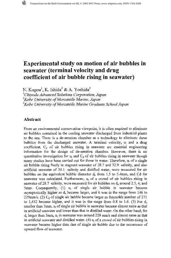
In a spherical bubble rising freely in the infmite stagnant liquid, when the velocity is in steady state, in other words, the bubble moves on the terminal velocity, the motion is in condition on the balance of buoyancy, weight force, and drag force acting on the gas bubble. Then, it is expressed by eqn (1).
From eqn (l), the terminal velocity and the drag coefficient can be written as follows.
2.2 Major Factor Affect the Terminal Velocity
Many past studies [4,5] show that the bubble size, density of liquids, viscosity of liquid and surface tension give an influence on the terminal velocity with varying the shapes and motion of bubble in the liquids. Clift et al. 141, showed the following three dimensionless numbers to presume the shapes and the terminal velocity of bubble.
Re means the dimensionless terminal velocity of bubble, Eo means the ratio of buoyancy and surface tension for the bubble, and M means the value for the influences of viscosity and surface tension against the bubble. By using eqns (4) to (6), eqn (2) is expressed as eqns (7) and (8).
From eqns (7) and (S), it can be understood that the terminal velocity will be affected by the bubble size, density of liquids, viscosity of liquid and surface tension. In seawater, various salts are dissolved, and the salinity and seawater temperature will affect the seawater properties of density, viscosity, and surface tension, etc. Generally, the density, viscosity, and surface tension become higher, as the salinity becomes higher or the seawater temperature becomes lower. Furthermore, for a single air bubble rising in water, Clift et al. [4], showed the terminal velocity of air bubble from 0.5 to 15mm is affected by the surface-active
Transactions on the Built Environment vol 68, © 2003 WIT Press, www.witpress.com, ISSN 1743-3509

contaminants. When the surface-active contaminants in water are absorbed on the interface of air bubble and water, the viscosity and surface tension on the surface of air bubble locally increase and reduce, respectively. A few surface-active contaminants in water decrease the terminal velocity of air bubble. In seawater, various marine organic materials such as plankton are contained, and those will act like the surface-active contaminants. From above, the major factors which affect the terminal velocity of air bubble rising in seawater, are the seawater properties (density, viscosity, and surface tension), the salinity, the air bubble size, and the marine organic materials.
2.3 Seawater properties, salinity, and BOD
As described in section 2.2, it is important to c o n f i i the seawater properties (density, viscosity, and surface tension), the salinity, and the marine organic materials, with the terminal velocity of air bubble rising in seawater. The coastal natural seawater (hereafter called seawater) was sampled in Kobe, Japan, and the salinity and kinetic viscosity of seawater were measured. The density and surface tension of seawater were calculated based on the salinity and temperature measured for seawater. To c o n f i i the influence of the marine organic materials in seawater, the terminal velocity of air bubble rising in artificial seawater in which there are no marine organic materials, was measured and compared with that in seawater.
2.3.1 Salinity and BOD Salinity is defied as the sum total of concentration of dissolved salts, and expressed as weight gram of dissolved salts per one kilogram of seawater. In this study, the chlorinity was measured by using an ion chromatograph (DIONEX DX-AQ, analytical columns: AS 12A and AG 12A, eluent: 0.3mM NaOH-2.7mM Na2C03 mixed solution, detector: electric conductivity detector), and converted into the salinity from eqn (9) [7].
BOD (Biochemical Oxygen Demand) is an index which shows quantity of organic material in seawater, and it was measured as the quantity of oxygen consumed by the aerobic bacteria during 5 days at 20°C in accordance with diaphragm electrode method [g]. Table 1 shows the salinity and BOD of seawater and artificial seawater.
Table 1. Salinitv and BOD
Seawater-l
Seawater-2
Artificial seawater
Salinity (%) 32.9
BOD (mg/l)
3.2
28.7
34.1
2.8
Transactions on the Built Environment vol 68, © 2003 WIT Press, www.witpress.com, ISSN 1743-3509
As shown in Table 1, two kinds of seawater were used in this study, and the salinity and BOD of seawater-l arc higher than those of seawater-2. The accuracy of measurement is&0.1%0 for salinity, and t o . l mgll for BOD.
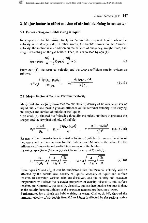
2.3.2 Kinetic viscosity For seawater and artificial seawater in the temperature of 10.3 to 34.6OC, the kinetic viscosity was measured by using a glass capillary viscometer (KABURAGI, Type-OA) and a water bath with temperature control in accordance with JIS [9]. Table 2 shows the kinetic viscosities for three samples as shown in Table 1. The accuracy of measurement is estimated to be 8%.
Table 2. Kinetic viscositv Temperature ("C) [upper]
From Table 2, it is observed that the kinetic viscosity of seawater and artificial seawater becomes lower as the temperature becomes higher. Furthermore, it is found that the marine organic materials on BOD of 2.8 to 3.2 mg/l hardly affect the kinetic viscosity of seawater. However, when the marine organic materials are absorbed and concentrated on the air bubble rising in seawater as mentioned in section 2.2, those may affect the terminal velocity.
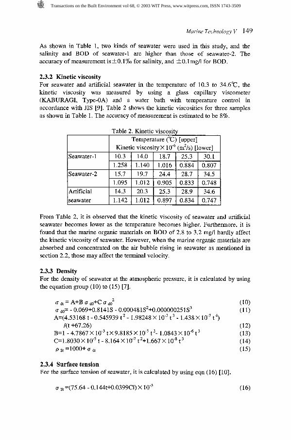
2.3.3 Density For the density of seawater at the atmospheric pressure, it is calculated by using the equation group (10) to (15) [7].
2.3.4 Surface tension For the surface tension of seawater, it is calculated by using eqn (16) 1101.
Transactions on the Built Environment vol 68, © 2003 WIT Press, www.witpress.com, ISSN 1743-3509
3 Experimental apparatus and condition
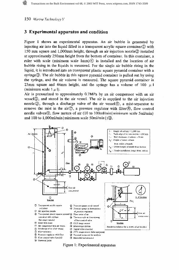
Figure 1 shows an experimental apparatus. An air bubble is generated by injecting air into the liquid filed in a transparent acrylic square containera with 150 mm square and 1,000mm height, through an air injection nozzle@ installed at approximately 250mm height from the bottom of container. In this container, a ruler with scale (minimum scale lmm)@ is installed and the location of air bubble rising in the liquids is measured. For the single air bubble rising in the liquid, it is introduced into an transparent plastic square pyramid container with a syringe@. The air bubble in this square pyramid container is pulled out by using the syringe, and the air volume is measured. The square pyramid container is 23mm square and 44mm height, and the syringe has a volume of 100 p 1 (minimum scale 1 ,U 1). Air is pressurized to approximately 0.7MPa by an air compressor with an air vessela, and stored in the air vessel. The air is supplied to the air injection nozzle@, through a discharge valve of the air vessel@, a mist-separator to remove the mist in the airs, a pressure regulator with filter@, flow control needle valves@, flow meters of air (10 to lOOml/min{minimum scale S d m i n ) and 100 to l,OOOml/min{minimum scale SOmI/min))@.
Air u ble f fom air compressor
. . . . . . . . .
h : Height of column = 1,000 mm i : Each edge of square section = 150 mm t : Wall thickness of column = 5 mm hl : Helght of water column
from outlet of nozzle h, : Outlet height of nozzle fom bottom
hb : Nozzle installation height from bottom
0 Transparent a w l i c square @D Pressure gauge on air vessel container @ Pressure gauge at downstream
@ Air injection nozzle of pressure regulator O Tramparent piastic square pyramid @ Flow meter of air
container ~ 7 t h syringe @ Thermocouple at downstream (for smgle bubble)
- - - - . . - . of flow control valve
@ Ruler with scale E9 CCD image sensor a Air compressor with ar vessel @ Microscope system Nozzle installation for a crowd of a ~ r bubbles 8 Discharge valve of air vessel @ Distal *deo recorder 0 Mist-separator @ CCD image sensor slide equipment @ Pressure regulator withfilter @ Personal computer for analysis 8 Flow control valve (needle) @ Mercurial thermometer Q3 Universal Joint
Figure 1 : Experimental apparatus
Transactions on the Built Environment vol 68, © 2003 WIT Press, www.witpress.com, ISSN 1743-3509

The air injection nozzle@can be exchanged for the several sizes by using the universal joint@, and the different sizes of air bubble can be generated. The temperature of liquid is measured by using a mercurial thermometer@ installed in the square containera. The temperature of air injected in the liquid is measured by using type-T thermocouple@ installed at the downstream of the flow control needle valve. The motion of air bubble rising in the liquid is recorded in Hi-8 digital video tape by a digital video recorder (30 frames per second)@ through a high-resolution quick microscope system@. The high-resolution quick microscope system@ has a CCD image sensor (1/2", 0.9M pixels)@, and the CCD image sensor can be manually moved upward with a CCD image sensor slide equipment@ in the same speed as rising air bubble. The digital movie of air bubble is imported from the digital video recorder@ to a personal computer@, and stop motion digital photographs of air bubble are made by dividing the movie frame by frame. The locations and projected areas of air bubble can be measured and observed from the stop motion digital photographs, by using a digital photograph measurement and analysis software in the personal computer@. Figure 2 shows an air bubble supply cup. In this experiment, the air bubble supply cup is also used to serve a single air bubble instead of the air injection nozzle@, especially when the velocity of air bubble does not reach to the terminal velocity within the height of the square container@ due to the high initial velocity in the air injection nozzle of smaller size. In this case, a known volume of air is injected into the air bubble supply cup made of the transparent plastic and shaped three forth of hemispherical cup with 31mm diameters, by using the syringe as same as that on the transparent plastic square pyramid container with a syringe@. This cup is set at lOOmm upper from bottom of the square container@. This cup can be rotated with a wire and an elastic band connected the cup, and the air bubble can be released from the cup without the initial velocity.
Figure 2: Air bubble supply cup
Water surface
Flow area of a crowd of air bubbles
Air injection nozzle
te of air : Qa
Figure 3: Flow area in a crowd of air bubbles
Transactions on the Built Environment vol 68, © 2003 WIT Press, www.witpress.com, ISSN 1743-3509

In generating of a crowd of air bubbles, the air injection nozzle@ is used. In this case, the nozzle outlet is pointed at the direction of 45 degree downward as shown in the lower right of Figure 1, to eliminate the effect of the initial upward velocity in the air injection. Table 3 shows the experimental condition. In this study, three kinds of water such as seawater, artificial seawater, and distilled water, were used to confirm the influence on the dissolved salts and the organic materials for the single air bubble in seawater. For the experiment on a crowd of air bubbles, seawater was used.
Table 3. Experimental condition l ~ e s t water Ifor single air l~eawater (32.9%0, 28.7%0), Artificial
l bubble l seawater (34.1 %o), Distilled water (one I l time distillation for tar, water)
Injection gas l Air Internal Ifor single air 10.19,0.51, 1.50,4.01
for a crowd of air bubble
Seawater (28.7%0)
diameter of air injection 4 (mm)
4 Method of analysis
Water head @outlet of nozzle Temperature of test water
4.1 Equivalent bubble diameter
bubble
for a crowd of air bubble
Approximately 0.58 m - 0.82m Atmospheric Temperature (16.3"C - 30.4"C)
The shapes of air bubble will vary according to the volume of air bubble and fluid properties, for instance, sphere, ellipsoid, etc. Therefore, for the characteristic length of air bubble, the equivalent bubble diameter which is the diameter of sphere having the equivalent volume is usually used. Then, the equivalent bubble diameter for the single air bubble is calculated by using eqn (17) based on the measured volume of air bubble. On the other hand, for a crowd of air bubbles, it is difficult to measure the volume of any air bubbles. Then, in this study, the equivalent bubble diameter for a crowd of air bubbles is calculated by using eqn (18) based on the measured projected area of any air bubble on the stop motion digital photographs.
0.51,0.70,0.90
d, = (for single air bubble)
(for a crowd of air bubbles)
Transactions on the Built Environment vol 68, © 2003 WIT Press, www.witpress.com, ISSN 1743-3509
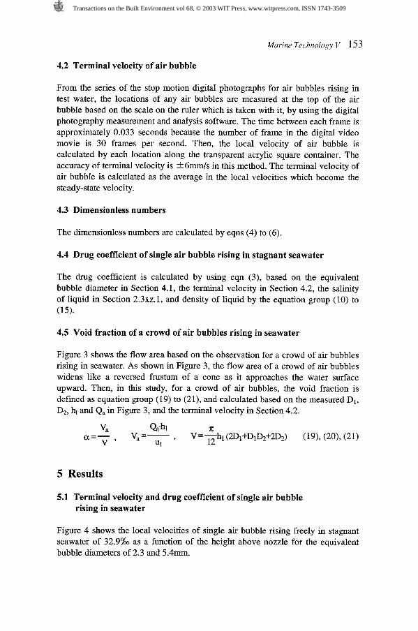
4.2 Terminal velocity of air bubble
From the series of the stop motion digital photographs for air bubbles rising in test water, the locations of any air bubbles are measured at the top of the air bubble based on the scale on the ruler which is taken with it, by using the digital photography measurement and analysis software. The time between each frame is approximately 0.033 seconds because the number of frame in the digital video movie is 30 frames per second. Then, the local velocity of air bubble is calculated by each location along the transparent acrylic square container. The accuracy of terminal velocity is k6mrnIs in this method. The terminal velocity of air bubble is calculated as the average in the local velocities which become the steady-state velocity.
4.3 Dimensionless numbers
The dimensionless numbers are calculated by eqns (4) to (6).
4.4 Drug coefficient of single air bubble rising in stagnant seawater
The drug coefficient is calculated by using eqn (3), based on the equivalent bubble diameter in Section 4.1, the terminal velocity in Section 4.2, the salinity of liquid in Section 2.3xz.1, and density of liquid by the equation group (10) to (15).
4.5 Void fraction of a crowd of air bubbles rising in seawater
Figure 3 shows the flow area based on the observation for a crowd of air bubbles rising in seawater. As shown in Figure 3, the flow area of a crowd of air bubbles widens like a reversed frustum of a cone as it approaches the water surface upward. Then, in this study, for a crowd of air bubbles, the void fraction is defined as equation group (19) to (21), and calculated based on the measured D,, DZ, h, and Q, in Figure 3, and the terminal velocity in Section 4.2.
5 Results
5.1 Terminal velocity and drug coefficient of single air bubble rising in seawater
Figure 4 shows the local velocities of single air bubble rising freely in stagnant seawater of 32.9% as a function of the height above nozzle for the equivalent bubble diameters of 2.3 and 5.4mm.
Transactions on the Built Environment vol 68, © 2003 WIT Press, www.witpress.com, ISSN 1743-3509

0 100 200 300 400 500 600 Height above nozzle z (mm)
Figure 4: Velocity of single air bubble rising in seawater as a function of height above nozzle
In Figure 4, the local velocities of air bubble asymptotically approach to steady- state value. The initial local velocity higher than the steady-state velocity is caused by the inertia of injected air bubble from nozzle. The oscillation of the local velocity would relate to the zigzag or spiral trajectory due to the wake as shown in previous studies [4] and the changing on shapes of air bubble rising in seawater. The terminal velocity of air bubble was calculated as average in the local velocities which become the steady-state velocity.
Figure 5 shows the comparison between terminal velocities of single air bubble rising freely in stagnant seawater, artificial seawater, and distilled water as a function of the equivalent bubble diameter. The accuracy of equivalent bubble diameter is i0.15mm. In Figure 5, also shown is the curve of the terminal velocity of air bubble rising in pure water at 20°C by Clift, et al. 141.
400 I l I A : Seawater (l). 32.9% salinity, - 350 16.39: - 25.69:. nozzle
1 : Seawater (2). 28.7% salinity. 27.6% - 30.4%. cup - 300 0 : Distilled water,
3
h 250 .- 0
g 200 a
150
G 100
1 .O 2.0 3 .O 4.0 5 .O 6.0 Equivalent bubble diameter d. (mm)
Figure 5: Comparison between terminal velocities of single air bubble rising in seawater, artificial seawater, distilled water as a function of equivalent bubble diam
Transactions on the Built Environment vol 68, © 2003 WIT Press, www.witpress.com, ISSN 1743-3509

From Figure 5, it is observed for air bubbles on the equivalent bubble diameter of 1.5 to 5.4mm as follows. (1) The terminal velocities in seawater and artificial seawater are almost same
and become asymptotically higher as the equivalent bubble diameter becomes larger. The terminal velocities are in the range from 146 to 2 2 9 d s .
(2) For the equivalent bubble diameter smaller than 3mm, the terminal velocities in seawater become lower than those in distilled water. On the other hand, for the equivalent bubble diameter larger than 3mm, the terminal velocities are almost same as those in distilled water, and around 2 2 0 d s .
(3) The terminal velocities in seawater become lower than those in pure water. Especially, for the equivalent bubble diameter smaller than 2mm, the terminal velocity becomes more than 40% lower as compared with that in pure water.
From above observations, it is found that the marine organic materials on BOD of 2.8 to 3.2 mgfl give little influence on the terminal velocity because the terminal velocity in seawater is almost same as that in artificial seawater. On the other hand, the dissolved salts affect the terminal velocity for the air bubbles of 2 to 3mm because the terminal velocities in seawater and artificial seawater are maximum 30% lower than that in distilled water. In this bubble size, Clift et al. [4] showed that the terminal velocity becomes especially sensitive for contaminants, then, this lower terminal velocity would mainly cause some contaminants in seawater including the dissolved salts.
Figure 6 shows the drug coefficient of single air bubble rising freely in stagnant seawater as a function of Reynolds number of 271 to 1,432. Table 4 shows the terminal velocity, dimensionless numbers, and drug coefficient for single air bubble rising freely in stagnant seawater. From Figure 6, the drug coefficient becomes larger as Reynolds number becomes higher in the region of Reynolds number of 271 to 1,432, and it is in the range from 0.8 to 1.6. In this region of Reynolds number, the shapes of air bubbles were ellipsoidal.
0 300 600 900 1,200 1,500 Reynolds number Re
Figure 6: Drug coefficient as function of Reynolds number for single air bubble rising in seawatewr
Transactions on the Built Environment vol 68, © 2003 WIT Press, www.witpress.com, ISSN 1743-3509
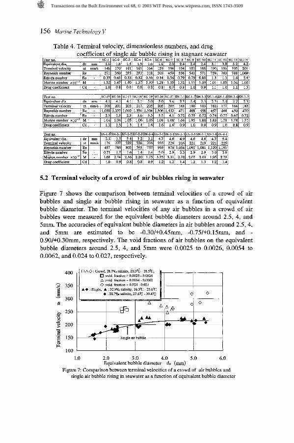
Table 4. Terminal velocity, dimensionless numbers, and drug coefficient of single air bubble rising in stagnant seawater
5.2 Terminal velocity of a crowd of air bubbles rising in seawater
Figure 7 shows the comparison between terminal velocities of a crowd of air bubbles and single air bubble rising in seawater as a function of equivalent bubble diameter. The terminal velocities of any air bubbles in a crowd of air bubbles were measured for the equivalent bubble diameters around 2.5, 4, and 5mm. The accuracies of equivalent bubble diameters in air bubbles around 2.5,4, and 5mrn are estimated to be -0.30/+0.45mm, -0.75/+0.15mm, and - 0.90/+0.30rnm, respectively. The void fractions of air bubbles on the equivalent bubble diameters around 2.5, 4, and 5mm were 0.0025 to 0.0026, 0.0054 to 0.0062, and 0.024 to 0.027, respectively.
OAO :Crowd, 28.7% salinity, 20.393 - 28.593, :void fraction = 0.0025 - 0.0026
A :void fraction = 0.0054 - 0.0062 0 :void fraction = 0.024 - 0.027
A+ : Single, A : 32.9% salinity, 16.393 - 25.693 + : 28.7% salinity. 27.693 - 30.493
Single air bubble S 1 .O 2.0 3.0 4.0 5 .O 6.0
Equivalent bubble diameter d, (mm) Figure 7: Comparison between terminal velocities of a crowd of air bubbles and
single air bubble rising in seawater as a function of equivalent bubble diameter
Transactions on the Built Environment vol 68, © 2003 WIT Press, www.witpress.com, ISSN 1743-3509

From Figure 7, it is observed for air bubbles on the equivalent bubble diameters around 2 . 5 ~ ( a =0.0025 to 0.0026), 4mm ( a =0.0054 to 0.0062), and 5mm ( a =0.024 to 0.027) as follows. (1) The terminal velocities are 251 to 2 6 4 d s , 248 to 2 8 5 d s , and 279 to
3 2 2 d s for the air bubbles around 2.5, 4, and 5mm, respectively. The terminal velocity tends to be higher as the equivalent diameter becomes larger.
(2) The terminal velocities of the air bubbles around 2.5, 4, and 5mm are 60 to 7lmmh (31 to 37%), 33 to 7 6 d s (15 to 36%), and 64 to 106mm/s (29 to 49%) higher as compared with the single air bubble, respectively.
This increase of terminal velocity as compared with the single air bubble would be mainly caused by the seawater upward flow which occurs due to the difference between air-seawater two phase density and seawater density.
6 Conclusion
The terminal velocities of a single air bubble rising freely in stagnant seawater of 28.7 and 32.9% salinity, and also artificial seawater of 34.1% salinity and distilled water, were measured for air bubbles on the equivalent bubble diameter from 1.5 to 5.4mm. Then, the drug coefficient of single air bubble freely in stagnant seawater was investigated based on the measured terminal velocities. Furthermore, the terminal velocities of a crowd of air bubbles rising in seawater of 28.7% salinity, were also measured for air bubbles on the equivalent bubble diameters around 2.5,4, and 5mm. From experimental results, it is concluded as follows. (1) The terminal velocity of single air bubble rising freely in stagnant seawater
becomes asymptotically higher as the equivalent bubble diameter becomes larger, and it is in the range from 146 to 2 2 9 d s .
(2) The drug coefficient of single air bubble rising freely in stagnant seawater becomes larger as Reynolds number becomes higher in the region of Reynolds number of 271 to 1,432, and it is in the range from 0.8 to 1.6.
(3) For the equivalent bubble diameter smaller than 3mm, the terminal velocities of single air bubble rising freely in stagnant seawater become almost same as those in artificial seawater and lower than those in distilled water. On the other hand, for the equivalent bubble diameter larger than 3mm, the terminal velocities in seawater are around 2 2 0 d s and almost same as those in artificial seawater and distilled water.
(4) In a crowd of air bubbles rising in seawater, the terminal velocities of air bubbles around 2.5mm ( a =0.0025 to 0.0026), 4mm ( a =0.0054 to 0.0062), and 5mm (a=0.024 to 0.027), become 60 to 7 l d s (31 to 37%), 33 to 7 6 d s (15 to 36%), and 64 to 1 0 6 d s (29 to 49%) higher as compared with the single air bubble, respectively.
Our data will be provided for a basic engineering design and further investigation on the de-aeration in the seawater cooling system.
Transactions on the Built Environment vol 68, © 2003 WIT Press, www.witpress.com, ISSN 1743-3509
158 Marine Trchnologv V
Nomenclature
Ab : projected area of air bubble (m2), Cd : drug coefficient (dimensionless) , Cl : chlorinity ( S ) , d, : equivalent bubble diameter defied as eqns (17) and (18) (m), D1 : diameter of flow area in a crowd of air bubbles at the nozzle outlet as shown in Figure 3 (m), D2 : diameter of flow area in a crowd of air bubbles at the water surface as shown in Figure 3 (m), Eo : E6tv6s number, g : acceleration of gravity (m/s2), hl : height from nozzle outlet to water surface in transparent acrylic square container (m), M : Morton number, n : number of the series of the stop motion digital photographs for any air bubbles in a crowd of air bubbles, Q, : flow rate of air injected in transparent acrylic square container (m3/s), Re : Reynolds number, S : salinity ( S ) , t : temperature ("C), U, : terminal velocity (m/s), U, : local velocity at location z (m/s), V : volume of flow area for a crowd of air bubbles in Figure 3 (m3), V, : total air volume in transparent acrylic square container (m3), Vb : volume of a bubble (m3), z : height above nozzle of experimental apparatus (m), (Y. : void fraction defied as equation group (19) to (21), p L: viscosity of liquid (Pa-S), p G: density of gas (kg/m3), p L: density of liquid (kg/m3), p S,:
density of seawater at t°C (kg/m3), o : surface tension (Nlm), a S,: surface tension of seawater at t°C (Nlm), a dt: sigma value for seawater density at t°C, a
sigma value for seawater density at 0°C.
References
Abe, T., Ka iyou no Kagaku, Japan Broadcast Publishing Co., Ltd.: Tokyo, pp. 44-47,126-129,155-164, 1975. (in Japanese)
Harada, T., 4@' Symposium of JSCE, II-274, pp. 646-647, 1993. (in Japanese) Chanson, H., Air-Bubble Entrainment in Free-Su$ace Turbulent Shear Flows, Academic Press : London and San Diego, 1996. Clift, R., Grace, J. R. & Weber, M. E., Bubbles, Drops, and Particles, Academic Press : New York and London, 1978. Bhaga, D. & Weber, M. E., Bubbles in viscous liquids : shapes, wakes and velocities, J. of Fluid Mech., Vo1.105, pp.61-85, 1981. Kugou, N., Ishida, K. & Yoshida, A., Study on motion of air bubbles in seawater (terminal velocity of single air bubble rising in seawater), 6gh Annual Meeting of JIME, ISlO1, pp. 11-1 8,2002. Nishimura, M., Kaiyou Kagaku, Sangyou Tosyo: Tokyo, pp. 10-12, 15, 1983. (in Japanese) JIS K-0102,21., 32.3,1998. (in Japanese) JIS K-2283,5., 2000. (in ~ a ~ a n e s e )
[l01 The Central Meteorological Observatory, Hydrographical Tables, pp. 87, Japan Weather Association, 198 1. (in Japanese)
[l11 JSME, Handbook of Gas-Liquid Two- Phase Flow Technology, Corona Publishing Co., Ltd. : Tokyo, 1989. (in Japanese)
Transactions on the Built Environment vol 68, © 2003 WIT Press, www.witpress.com, ISSN 1743-3509