Embed Size (px)
Citation preview
Experimental Study on impact of temperature variations in
CNC Milling, during dry machining and wet machining for
Al and CI material
Balasubramanian S1, Vinayagamoorthi M.A
2, Mohan Kumar R.S
3, Rubakumar K
4, Sounder R
5
Abstract - The study of heat has become prominent in metal cutting as it has very critical
influence on machining processes. Any machining process involves three basic elements viz.,
chip, tool and workpiece. Heat developed among these three elements is vital and may cause
considerable effect in the machining performance. The heat is generated due to several factors
among which friction between the tool and the chip is one of the reasons. The effect of heat
generation can be viewed in two forms, one from the workpiece and another form the cutting
tool. In this paper a review has been done on the various sources of heat generation and its
considerable effects on the life of cutting tool and the quality of the machined part. A study has
also been conducted on the temperature distribution on the different regions. Generation of heat
can be controlled by various machining parameters and cutting tool geometry, this paper also
focuses on various factors that influences on the temperature generation. Although any amount of
heat can be generated during machining, the determination of cutting temperature is also one of
the important factors. A review is also done on various measurement techniques of cutting
temperature. For the betterment of the machining, the perspective of heat generation in metal
cutting is a prominent factor.
Index Terms - CNC milling, cutting temperature, dry machining, depth of cut, heat generation,
spindle speed, wet machining
1 INTRODUCTION
As a large amount of plastic strain
is involved in metal cutting, almost 99%
of heat is transferred to chip, cutting tool
and the work piece, while more than 1%
of work is stored as an elastic energy. The
three sources of heat generation include
Shear-plane (AB), where the actual
plastic deformation occurs, second is the
Tool-chip interface (BC), due to the
friction between tool and chip and the
final source is where Tool-work piece
interface (BD), which occurs at flank
surface. As a large amount of plastic
strain is involved in metal cutting, almost
99% of heat is transferred to chip, cutting
tool and the workpiece, while more than
1% of work is stored as an elastic energy.
The three sources of heat generation
include Shear-plane (AB), where the
actual plastic deformation occurs, second
is the Tool-chip interface (BC), due to the
friction between tool and chip and the
final source is where Tool-work piece
interface (BD), which occurs at flank
surface.
1Associate Professor, Department of Mechanical Engineering, Kumaraguru College of
Technology, Coimbatore, Tamil Nadu, India. E-mail : [email protected] 2,3
Assistant Professor, Department of Mechanical Engineering, Kumaraguru College of
Technology, Coimbatore, Tamil Nadu, India. E-mail : [email protected],
Student, Department of Mechanical Engineering, Kumaraguru College of Technology,
Coimbatore, Tamil Nadu, India. E-mail : [email protected], [email protected]
International Journal of Scientific & Engineering Research Volume 11, Issue 7, July-2020 ISSN 2229-5518
224
IJSER © 2020 http://www.ijser.org
IJSER
Due to the thermal distortion and thermal
expansion during cutting, there may
chance of dimensional inaccuracy of the
job Because of the oxidation, there is a
chance of surface damage. In some cases,
micro cracks at the surface, corrosion and
burning of job can also be seen. The
reduction in the life of tool and the poor
quality of the job is the cause for
temperature generation
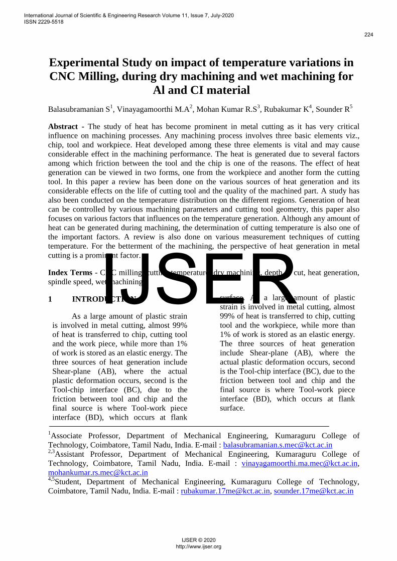
Fig.1 Cutting Speed Vs Percentage of
total heat
From this study it can be concluded that
heat distribution in the chip, workpiece and
tool are in the ratio 80:10:10.
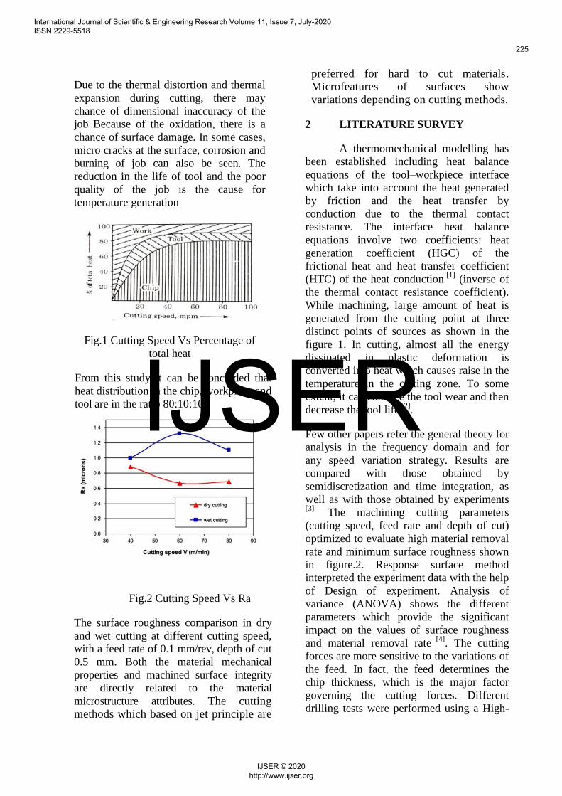
Fig.2 Cutting Speed Vs Ra
The surface roughness comparison in dry
and wet cutting at different cutting speed,
with a feed rate of 0.1 mm/rev, depth of cut
0.5 mm. Both the material mechanical
properties and machined surface integrity
are directly related to the material
microstructure attributes. The cutting
methods which based on jet principle are
preferred for hard to cut materials.
Microfeatures of surfaces show
variations depending on cutting methods.
2 LITERATURE SURVEY
A thermomechanical modelling has
been established including heat balance
equations of the tool–workpiece interface
which take into account the heat generated
by friction and the heat transfer by
conduction due to the thermal contact
resistance. The interface heat balance
equations involve two coefficients: heat
generation coefficient (HGC) of the
frictional heat and heat transfer coefficient
(HTC) of the heat conduction [1]
(inverse of
the thermal contact resistance coefficient).
While machining, large amount of heat is
generated from the cutting point at three
distinct points of sources as shown in the
figure 1. In cutting, almost all the energy
dissipated in plastic deformation is
converted into heat which causes raise in the
temperature in the cutting zone. To some
extent, it can enhance the tool wear and then
decrease the tool life [2]
.
Few other papers refer the general theory for
analysis in the frequency domain and for
any speed variation strategy. Results are
compared with those obtained by
semidiscretization and time integration, as
well as with those obtained by experiments
[3]. The machining cutting parameters
(cutting speed, feed rate and depth of cut)
optimized to evaluate high material removal
rate and minimum surface roughness shown
in figure.2. Response surface method
interpreted the experiment data with the help
of Design of experiment. Analysis of
variance (ANOVA) shows the different
parameters which provide the significant
impact on the values of surface roughness
and material removal rate [4]
. The cutting
forces are more sensitive to the variations of
the feed. In fact, the feed determines the
chip thickness, which is the major factor
governing the cutting forces. Different
drilling tests were performed using a High-
International Journal of Scientific & Engineering Research Volume 11, Issue 7, July-2020 ISSN 2229-5518
225
IJSER © 2020 http://www.ijser.org
IJSER
Speed Steel drill with a 10 mm diameter and
a point angle of 118° in order to determine
the effect of feed and alloys on cutting
forces [5]
.
Particular attention is given to modeling of
the tool-chip, chip-work piece and tool-work
piece interfaces. Since the direct
temperature measurement at the chip-tool
interface are very complex, this work
proposes the estimation of the temperature
and the heat flux at the chip-tool interface
using the inverse heat conduction problem
technique. The shear energy created in the
primary zone, the friction energy produced
at the rake facechip contact zone and the
heat balance between the moving chip and
the stationary tool are considered. The
temperature distribution is solved using
finite difference method [6]
. The heat fluxes
generated by cutting processes lead to
thermal deformations in the tools.
Particularly, in precision machining it is
essential to know the amount of the process
heat and its distribution of heat fluxes into
tool, workpiece and chips. This paper
presents an extended methodology for the
calculation of these heat fluxes in machining
operations. Additionally, by comparison of
experimental results with finite element
simulations, the thermally caused tool center
point (TCP) displacements in turn-milling
operations are discussed [7]
. Chip-tool
interface temperature is closely connected to
cutting speed. With increase of cutting
speed, friction increases, this induces an
increase in temperature in the cutting zone.
With the increase in feed rate, section of
chip increases and consequently friction
increases this involves the increase in
temperatures [8]
.
To investigate the influence of material
microstructure changes on residual stresses
[9]. As main results, it was firstly
demonstrated by surface topography
analysis as both the white and dark layer are
the result of microstructural alterations
mainly due to rapid heating and quenching
[10]. Furthermore, it was found as both the
presence of white and dark layers influence
the residual stress profile [9]
. Microstructure
of cut surfaces is affected from the kind of
cutting process. Microstructural changes
during cutting of the materials are observed
with all of the cutting process other than
Abrasive water jet. Abrasive water jet
method can be effectively used in industrial
applications where no microstructural
changes and hardness reduction is essential
[10].
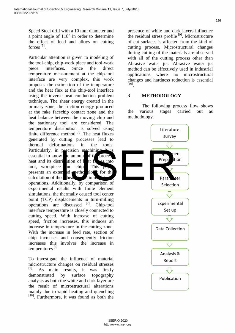
3 METHODOLOGY
The following process flow shows
the various stages carried out as
methodology.
Literature
survey
Parameter
Selection
Data Collection
Analysis &
Report
Publication
Experimental
Set up
Specimen Preparation
International Journal of Scientific & Engineering Research Volume 11, Issue 7, July-2020 ISSN 2229-5518
226
IJSER © 2020 http://www.ijser.org
IJSER
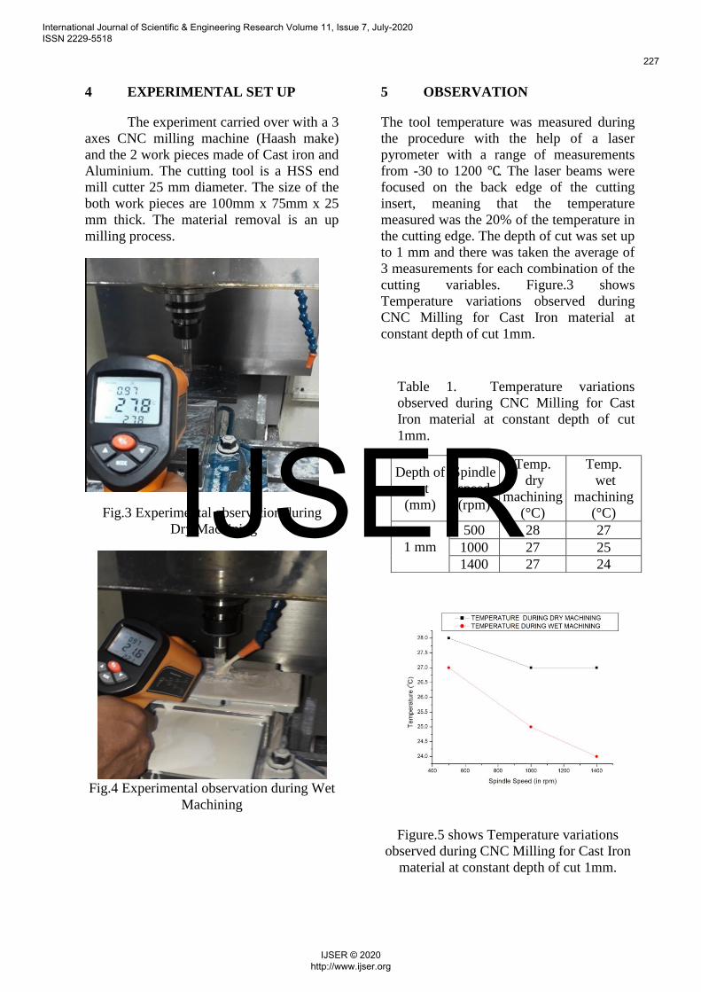
4 EXPERIMENTAL SET UP
The experiment carried over with a 3
axes CNC milling machine (Haash make)
and the 2 work pieces made of Cast iron and
Aluminium. The cutting tool is a HSS end
mill cutter 25 mm diameter. The size of the
both work pieces are 100mm x 75mm x 25
mm thick. The material removal is an up
milling process.
Fig.3 Experimental observation during
Dry Machining
Fig.4 Experimental observation during Wet
Machining
5 OBSERVATION
The tool temperature was measured during
the procedure with the help of a laser
pyrometer with a range of measurements
from -30 to 1200 ℃. The laser beams were
focused on the back edge of the cutting
insert, meaning that the temperature
measured was the 20% of the temperature in
the cutting edge. The depth of cut was set up
to 1 mm and there was taken the average of
3 measurements for each combination of the
cutting variables. Figure.3 shows
Temperature variations observed during
CNC Milling for Cast Iron material at
constant depth of cut 1mm.
Figure.5 shows Temperature variations
observed during CNC Milling for Cast Iron
material at constant depth of cut 1mm.
Table 1. Temperature variations
observed during CNC Milling for Cast
Iron material at constant depth of cut
1mm.
Depth of
cut
(mm)
Spindle
speed
(rpm)
Temp.
dry
machining
(°C)
Temp.
wet
machining
(°C)
1 mm
500 28 27
1000 27 25
1400 27 24
International Journal of Scientific & Engineering Research Volume 11, Issue 7, July-2020 ISSN 2229-5518
227
IJSER © 2020 http://www.ijser.org
IJSER
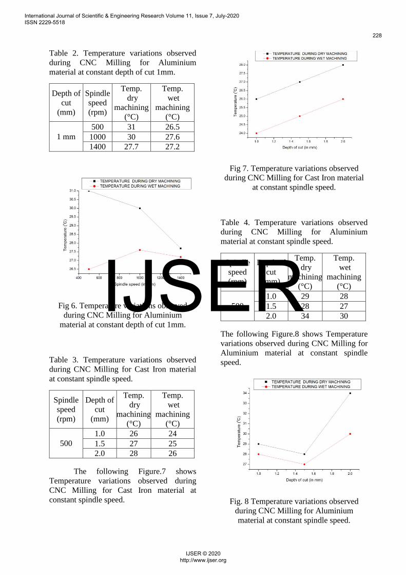
Table 2. Temperature variations observed
during CNC Milling for Aluminium
material at constant depth of cut 1mm.
Depth of
cut
(mm)
Spindle
speed
(rpm)
Temp.
dry
machining
(°C)
Temp.
wet
machining
(°C)
1 mm
500 31 26.5
1000 30 27.6
1400 27.7 27.2
Fig 6. Temperature variations observed
during CNC Milling for Aluminium
material at constant depth of cut 1mm.
Table 3. Temperature variations observed
during CNC Milling for Cast Iron material
at constant spindle speed.
Spindle
speed
(rpm)
Depth of
cut
(mm)
Temp.
dry
machining
(°C)
Temp.
wet
machining
(°C)
500
1.0 26 24
1.5 27 25
2.0 28 26
The following Figure.7 shows
Temperature variations observed during
CNC Milling for Cast Iron material at
constant spindle speed.
Fig 7. Temperature variations observed
during CNC Milling for Cast Iron material
at constant spindle speed.
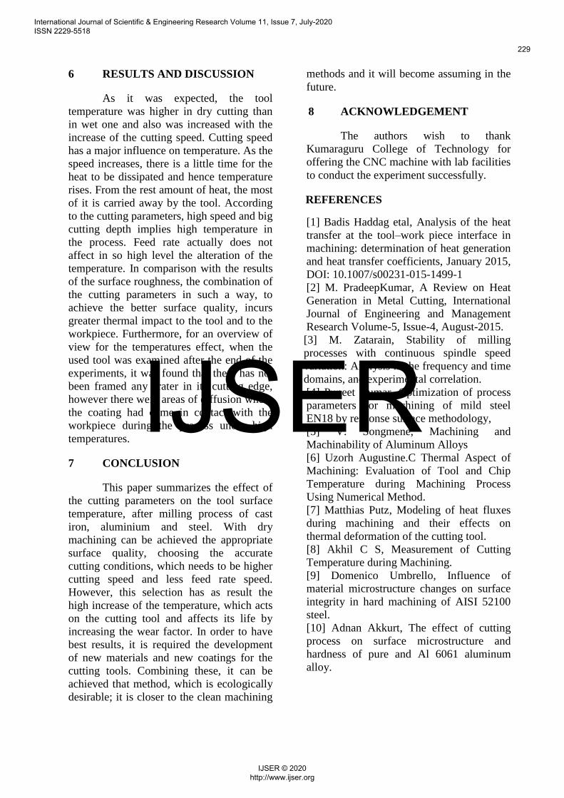
Table 4. Temperature variations observed
during CNC Milling for Aluminium
material at constant spindle speed.
Spindle
speed
(rpm)
Depth of
cut
(mm)
Temp.
dry
machining
(°C)
Temp.
wet
machining
(°C)
500
1.0 29 28
1.5 28 27
2.0 34 30
The following Figure.8 shows Temperature
variations observed during CNC Milling for
Aluminium material at constant spindle
speed.
Fig. 8 Temperature variations observed
during CNC Milling for Aluminium
material at constant spindle speed.
International Journal of Scientific & Engineering Research Volume 11, Issue 7, July-2020 ISSN 2229-5518
228
IJSER © 2020 http://www.ijser.org
IJSER
6 RESULTS AND DISCUSSION
As it was expected, the tool
temperature was higher in dry cutting than
in wet one and also was increased with the
increase of the cutting speed. Cutting speed
has a major influence on temperature. As the
speed increases, there is a little time for the
heat to be dissipated and hence temperature
rises. From the rest amount of heat, the most
of it is carried away by the tool. According
to the cutting parameters, high speed and big
cutting depth implies high temperature in
the process. Feed rate actually does not
affect in so high level the alteration of the
temperature. In comparison with the results
of the surface roughness, the combination of
the cutting parameters in such a way, to
achieve the better surface quality, incurs
greater thermal impact to the tool and to the
workpiece. Furthermore, for an overview of
view for the temperatures effect, when the
used tool was examined after the end of the
experiments, it was found that there has not
been framed any crater in its cutting edge,
however there were areas of diffusion where
the coating had come in contact with the
workpiece during the process under high
temperatures.
7 CONCLUSION
This paper summarizes the effect of
the cutting parameters on the tool surface
temperature, after milling process of cast
iron, aluminium and steel. With dry
machining can be achieved the appropriate
surface quality, choosing the accurate
cutting conditions, which needs to be higher
cutting speed and less feed rate speed.
However, this selection has as result the
high increase of the temperature, which acts
on the cutting tool and affects its life by
increasing the wear factor. In order to have
best results, it is required the development
of new materials and new coatings for the
cutting tools. Combining these, it can be
achieved that method, which is ecologically
desirable; it is closer to the clean machining
methods and it will become assuming in the
future.
8 ACKNOWLEDGEMENT
The authors wish to thank
Kumaraguru College of Technology for
offering the CNC machine with lab facilities
to conduct the experiment successfully.
REFERENCES
[1] Badis Haddag etal, Analysis of the heat
transfer at the tool–work piece interface in
machining: determination of heat generation
and heat transfer coefficients, January 2015,
DOI: 10.1007/s00231-015-1499-1
[2] M. PradeepKumar, A Review on Heat
Generation in Metal Cutting, International
Journal of Engineering and Management
Research Volume-5, Issue-4, August-2015.
[3] M. Zatarain, Stability of milling
processes with continuous spindle speed
variation: Analysis in the frequency and time
domains, and experimental correlation.
[4] Puneet Kumar, Optimization of process
parameters for machining of mild steel
EN18 by response surface methodology,
[5] V. Songmene, Machining and
Machinability of Aluminum Alloys
[6] Uzorh Augustine.C Thermal Aspect of
Machining: Evaluation of Tool and Chip
Temperature during Machining Process
Using Numerical Method.
[7] Matthias Putz, Modeling of heat fluxes
during machining and their effects on
thermal deformation of the cutting tool.
[8] Akhil C S, Measurement of Cutting
Temperature during Machining.
[9] Domenico Umbrello, Influence of
material microstructure changes on surface
integrity in hard machining of AISI 52100
steel.
[10] Adnan Akkurt, The effect of cutting
process on surface microstructure and
hardness of pure and Al 6061 aluminum
alloy.
International Journal of Scientific & Engineering Research Volume 11, Issue 7, July-2020 ISSN 2229-5518
229
IJSER © 2020 http://www.ijser.org
IJSER