Embed Size (px)
Citation preview

International Journal of Applied Engineering Research ISSN 0973-4562 Volume 12, Number 5 (2017) pp. 744-754
© Research India Publications. http://www.ripublication.com
744
Experimental Study of Two Way Half Slab Precast Using Triangular Rigid
Connection of Precast Concrete Component
Djoko Irawan1, Data Iranata1 and Priyo Suprobo1
1Department of Civil Engineering, Institut Teknologi Sepuluh Nopember, Indonesia.
Abstract
Precast concrete half slab system, which consists of precast
concrete at the bottom part and cast-in-site concrete at the
overtopping, is widely used as floor slab and commonly behave
as a one-way slab. However, the problems occur when the
precast half slab is designed as the two-way slab system. In this
system, the connection of between precast concrete slabs
should able to handle the two-way moment of the whole panel,
without causing any significant damages. Hence, an innovative
rigid connection between precast concrete slab components in
two-way half slab system is presented in this paper. The
objectives of this research are to conduct the experimental
study for proposed connection between precast concrete slab
components that behave as two-way half slab system. The 2200
mm × 2200 mm size of samples are performed using the
triangular shape of the rigid connection between precast
concrete slabs. The test is conducted using mid-span
concentrated loading-unloading up to failure condition.
The test results are observed and verified with the response of
monolith reinforced concrete slab system using the same
loading pattern. The verification results show that proposed
half slab system are able to withstand the two-way moment
loading. Although the carrying capacity is still slightly lower
than the monolith reinforced concrete slab system, the proposed
half slab system is able to apply as the structural component.
Keyword: half slab, precast concrete, reinforced concrete, rigid
connection, loading-unloading
INTRODUCTION
The precast concrete half slab is a structural slab system that
consists of two different concrete type at the half bottom and
the top part of the slab. The bottom part of the slab is made up
of the precast concrete component, while the top part is
contained of cast-in-site concrete material that so-called
overtopping, as presented in Fig.1. Generally, precast concrete
half slab system is acting limited as one-way slab only (ly/lx >
2), which is the primary moment loading is acting parallel to
the connection between precast concrete components.
Therefore, since such connection only resists the minor
moment loading, the simple connection is commonly applied
between the precast concrete components (as shown in Fig.2),
as presented by Wijanto and Takim [1]. However, the problems
occur when the precast half slab is designed as the two-way slab
system. Since the moment loading act in both X and Y
direction, the connection between the precast concrete
components should be able to handle the acting moment in the
corresponding direction. Otherwise, the crack damages will
occur along the corresponding direction. The real case of port
design that using the simple connection for two-way precast
concrete half slab system is presented by Irawan et al [2]. Fig.3
shows the simple connection of the precast concrete slab
component that applied in the port design. Furthermore, the
crack that occurs in the bottom part of the slab due to the
lacking capacity of the precast connection is depicted in Fig 4.
Concrete crack only occurs parallel to the connection between
precast concrete slabs.
This phenomenon indicates that the simple connection between
precast concrete slabs cannot resist the moment loading to the
corresponding direction. Hence, it is necessary to develop the
rigid connection that applied in this connection system that can
withstand the corresponding moment loading.
Figure 1. Half Slab Precast Concrete System
Figure 2. The simple connection is commonly applied
between the precast concrete components
Figure 3. The simple connection at the bottom part of half
slab precast
International Journal of Applied Engineering Research ISSN 0973-4562 Volume 12, Number 5 (2017) pp. 744-754
© Research India Publications. http://www.ripublication.com
745
Many studies about the connection of precast concrete half slab
have done previously by researchers. Hieber et al. [3] presented
the interlocking connection that able to withstand the shear
loading. Hence, the slab could be performed as diaphragm
appropriately. Kim and Shim [4] investigated the performance
of pre-tensioned half slab in the transverse direction and used
the looping connection in the longitudinal direction. Kim and
Shim [5] also investigated the crack width of half precast slab
using looping connection between precast components. Using
precast concrete also can reduce operation time substantially
comparing to cast in situ concrete. Moreover, Yardim [6]
proposed the connection for a precast thin panel that acts as
composite slabs for the permanent framework in a residential
building. Siswosukarto [7] proposed semi-precast slab as an
alternative method to promote the green construction
residential house project. Research about the flexure-shear
behavior of precast concrete deck panels with cast-in-place
concrete topping is also performed by Dowell. et al [8]. The
failure prediction of the panel is analyzed using modified.
However, this study only focused for the slab in one direction.
Additionally, Santos and Julio, [9] has studied about horizontal
friction between old and new concrete slab in half precast
system. The load transfer mechanism at the concrete to the
concrete interface is determined by several factors, such as
cohesion behavior, friction coefficient, and dowel action. Lee
at al [10] also studied about deflection of Reinforced Concrete
Half Slab. Vakhsouri, [11] studied about the length of
reinforcement adjacent to the crack where the compatibility of
strain between the steel and concrete is not maintained because
of partially bond breakdown and slip. However, most of those
previous study is limited for one-way half slab precast system.
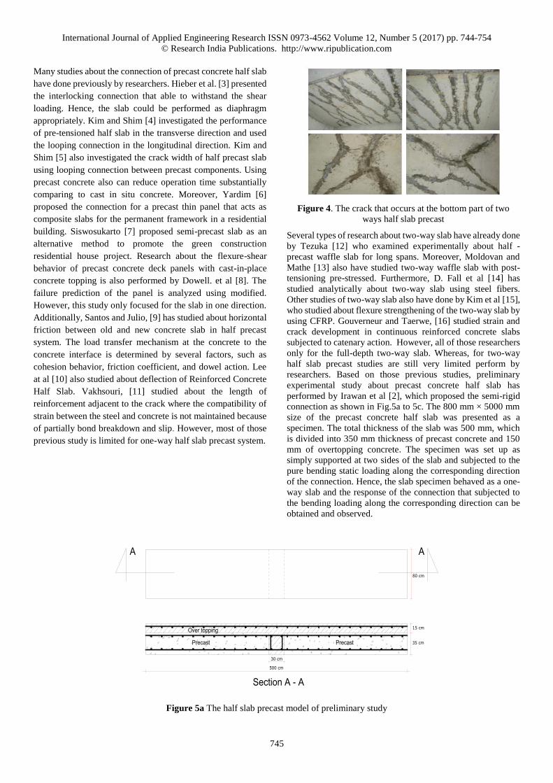
Figure 4. The crack that occurs at the bottom part of two
ways half slab precast
Several types of research about two-way slab have already done
by Tezuka [12] who examined experimentally about half -
precast waffle slab for long spans. Moreover, Moldovan and
Mathe [13] also have studied two-way waffle slab with post-
tensioning pre-stressed. Furthermore, D. Fall et al [14] has
studied analytically about two-way slab using steel fibers.
Other studies of two-way slab also have done by Kim et al [15],
who studied about flexure strengthening of the two-way slab by
using CFRP. Gouverneur and Taerwe, [16] studied strain and
crack development in continuous reinforced concrete slabs
subjected to catenary action. However, all of those researchers
only for the full-depth two-way slab. Whereas, for two-way
half slab precast studies are still very limited perform by
researchers. Based on those previous studies, preliminary
experimental study about precast concrete half slab has
performed by Irawan et al [2], which proposed the semi-rigid
connection as shown in Fig.5a to 5c. The 800 mm × 5000 mm
size of the precast concrete half slab was presented as a
specimen. The total thickness of the slab was 500 mm, which
is divided into 350 mm thickness of precast concrete and 150
mm of overtopping concrete. The specimen was set up as
simply supported at two sides of the slab and subjected to the
pure bending static loading along the corresponding direction
of the connection. Hence, the slab specimen behaved as a one-
way slab and the response of the connection that subjected to
the bending loading along the corresponding direction can be
obtained and observed.
Figure 5a The half slab precast model of preliminary study
35 cm
15 cm
30 cm
500 cm
80 cm
Over topping
Precast
AA
Section A - A
Precast

International Journal of Applied Engineering Research ISSN 0973-4562 Volume 12, Number 5 (2017) pp. 744-754
© Research India Publications. http://www.ripublication.com
746
Figure 5b The monolithic slab model of preliminary Study
Figure 5c. Experimental set up of preliminary study
Based on the experimental result, which presented in Table 1,
it was showed that the capacity of proposed precast concrete
half slab to resist the cracking moment was 16% lower than
monolith system. Therefore, to improve and increase the
capacity of the precast concrete half slab, this paper present
experimental study for proposed rigid connection between
precast concrete slab components in two-way half slab system.
Table 1. Comparison P crack and M crack between monolithic
slab and slab with connection
RESEARCH METHOD
This experimental study present 2200 mm × 2200 mm size of
the specimen using the rectangular shape of the rigid
connection between precast concrete slabs. The total thickness
of the proposed concrete half slab is 200 mm, which is divided
into 120 mm thickness of precast concrete and 80 mm of
overtopping concrete. Moreover, in order to prevent slip
between precast concrete and overtopping, several shear
connectors are added to its interface. Furthermore, the simply
supported at four sides of the precast concrete half slab are
applied. The detail experimental setup is illustrated in Fig. 6a
and 6b.
Figure 6a. Half slab precast model with triangular connection
50 cm
80 cm
MONOLIT
500 cm
BB
Section B - B
100 cm100 cm 100 cm 100 cm 100 cm
LOAD
Specimen
10 - 15
15.00
70.00
5.00 15.00
8 - 15
10 - 15
2.50
9.50
75.00
12.60
6.0270.00
2.50
9.50
75.00
70.00
2.50
9.50
70.00
60.10
5.00
75.00
5.007.50
15.00
220.00
7.505.00
70.00 75.007.50
15.00
12.50
74.32
5.007.50
3.918.59
12.5012.50
3.70
7.904.62
15.00
10.00
12.00
8.00
75.005.007.5052.50
International Journal of Applied Engineering Research ISSN 0973-4562 Volume 12, Number 5 (2017) pp. 744-754
© Research India Publications. http://www.ripublication.com
747
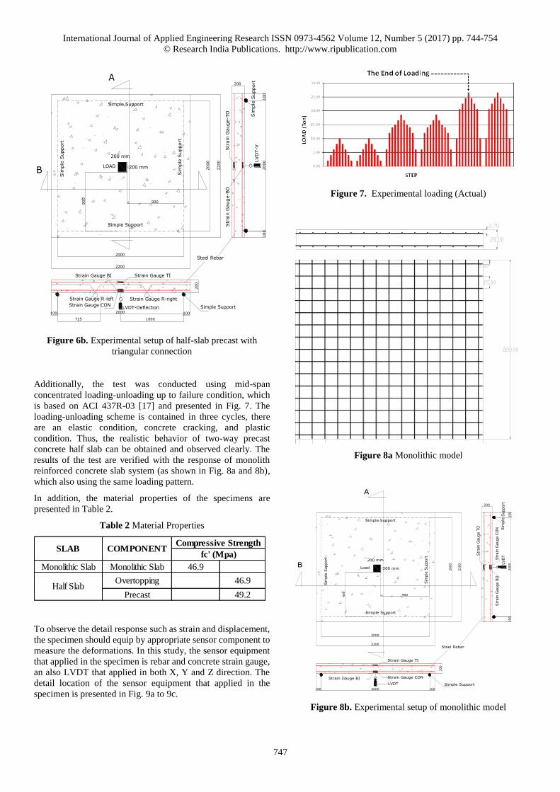
Figure 6b. Experimental setup of half-slab precast with
triangular connection
Additionally, the test was conducted using mid-span
concentrated loading-unloading up to failure condition, which
is based on ACI 437R-03 [17] and presented in Fig. 7. The
loading-unloading scheme is contained in three cycles, there
are an elastic condition, concrete cracking, and plastic
condition. Thus, the realistic behavior of two-way precast
concrete half slab can be obtained and observed clearly. The
results of the test are verified with the response of monolith
reinforced concrete slab system (as shown in Fig. 8a and 8b),
which also using the same loading pattern.
In addition, the material properties of the specimens are
presented in Table 2.
Table 2 Material Properties
To observe the detail response such as strain and displacement,
the specimen should equip by appropriate sensor component to
measure the deformations. In this study, the sensor equipment
that applied in the specimen is rebar and concrete strain gauge,
an also LVDT that applied in both X, Y and Z direction. The
detail location of the sensor equipment that applied in the
specimen is presented in Fig. 9a to 9c.
Figure 7. Experimental loading (Actual)
Figure 8a Monolithic model
Figure 8b. Experimental setup of monolithic model
2000
2200
2000
2200
LOAD
Simple Support
Sim
ple
Support
Sim
ple
Support
200 mm
200 mm
Simple Support
900900
Strain Gauge TI
100
200
2000100
LVD
T-VStr
ain
Gauge-T
O
100
200
2000
100
Strain Gauge CON
1000725
Strain Gauge BI
LVDT-Deflection
Str
ain
Gauge-B
O
B
Sim
ple
Support
Steel Rebar
A
Simple Support
Strain Gauge R-left Strain Gauge R-right
Monolithic Slab Monolithic Slab 46.9
Overtopping 46.9
Precast 49.2Half Slab
Compressive Strength
fc' (Mpa)SLAB COMPONENT
2000
2200
2000
2200
Load
200 mm
200 mm
900900
Strain Gauge CON
100
200
2000100
LVD
TStr
ain
Gauge T
O
100
2002000
100
Strain Gauge TI
LVDT
Str
ain
Gauge B
OStr
ain
Gauge C
ON
Simple Support
Sim
ple
Support
Sim
ple
Support
Simple Support
Steel Rebar
Simple Support
Sim
ple
Support
Strain Gauge BI
A
B
International Journal of Applied Engineering Research ISSN 0973-4562 Volume 12, Number 5 (2017) pp. 744-754
© Research India Publications. http://www.ripublication.com
748
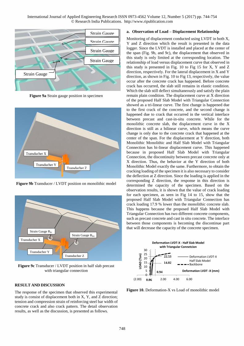
Figure 9a Strain gauge position in specimen
Figure 9b Transducer / LVDT position on monolithic model
Figure 9c Transducer / LVDT position in half slab precast
with triangular connection
RESULT AND DISCUSSION
The response of the specimen that observed this experimental
study is consist of displacement both in X, Y, and Z direction;
tension and compression strain of reinforcing steel bar width of
concrete crack and also crack pattern. The detail observation
results, as well as the discussion, is presented as follows.
a. Observation of Load – Displacement Relationship
Monitoring of displacement conducted using LVDT in both X,
Y and Z direction which the result is presented in the data
logger. Since the LVDT is installed and placed at the center of
the span (Fig. 9b, and 9c), the displacement that observed in
this study is only limited at the corresponding location. The
relationship of load versus displacement curve that observed in
this study is presented in Fig. 10 to Fig 15 for X, Y and Z
direction, respectively. For the lateral displacement in X and Y
direction, as shown in Fig. 10 to Fig 13, respectively, the value
occur after the concrete crack has happened. Before concrete
crack has occurred, the slab still remains in elastic condition.
Which the slab still deflect simultaneously and satisfy the plain
remain plain condition. The displacement curve at X direction
of the proposed Half Slab Model with Triangular Connection
showed as a tri-linear curve. The first change is happened due
to the first crack of the concrete, and the second change is
happened due to crack that occurred in the vertical interface
between precast and cast-in-situ concrete. While for the
monolithic concrete slab, the displacement curve in the X
direction is still as a bilinear curve, which means the curve
change is only due to the concrete crack that happened at the
center of the span. For the displacement at Y direction, both
Monolithic Monolithic and Half Slab Model with Triangular
Connection has bi-linear displacement curve. This happened
because in proposed Half Slab Model with Triangular
Connection, the discontinuity between precast concrete only at
X direction. Thus, the behavior at the Y direction of both
Monolithic Model exactly the same. Furthermore, to obtain the
cracking loading of the specimen it is also necessary to consider
the deflection at Z direction. Since the loading is applied in the
corresponding Z direction, the response in this direction is
determined the capacity of the specimen. Based on the
observation results, it is shown that the value of crack loading
for each specimen, as seen in Fig 14 to 15, show that the
proposed Half Slab Model with Triangular Connection has
crack loading 17.9 % lower than the monolithic concrete slab.
This happens because the proposed Half Slab Model with
Triangular Connection has two different concrete components,
such as precast concrete and cast in situ concrete. The interface
between those components is becoming the discontinue part
that will decrease the capacity of the concrete specimen.
Figure 10. Deformation-X vs Load of monolithic model
Transducher Z Transducher Y
Transducher X
Strain Gauge Rkr
Transducher Y
Strain Gauge Rkn
Transducher X
Transducher Z
Strain Gauge
CON
Strain Gauge
Strain Gauge
BI Strain Gauge
BO
Strain Gauge
0
510
15
2025
30
(2.00) - 2.00 4.00 6.00
LOA
D (
Ton
)
Deformation LVDT -X (mm)
Deformation LVDT-X - Half Slab Model with Triangular Connetcion
Deformation LVDT-XHalf Slab ModelBackbone
22.53
14.02
0.94
0.06

International Journal of Applied Engineering Research ISSN 0973-4562 Volume 12, Number 5 (2017) pp. 744-754
© Research India Publications. http://www.ripublication.com
749
Figure 11. Deformation-X vs Load of half slab precast with
triangular connection
Figure 12. Deformation-Y vs Load of monolithic model
Figure 13. Deformation-Y vs Load of half slab precast with
triangular connection
Figure 14 Deflection vs Load of monolithic model
Figure 15. Deflection vs Load of half slab precast with
triangular connection
b. Observation of Load – Rebar Stress Relationship
Monitoring of rebar strain conducted using strain gauge in both
X and Y direction which the result is presented in the data
logger. The strain gauge is installed and placed in both tension
and compression reinforcing steel bar. The relationship of load
versus stress curve for both tension and compression
reinforcing steel bar that observed in this study is presented in
Fig. 16 to Fig. 23, respectively. The response of the steel bar is
similar with the concrete displacement.
The rebar that located in the X direction of the proposed Half
Slab Model with Triangular Connection has a tri-linear curve.
Again, this happened due to the discontinuity between precast
concrete components. The first change of the tri-linear curve is
happened due to the first crack of the concrete slab, and the
second change is happened due to crack that occurred in the
vertical interface between precast and cast-in-situ concrete.
Figure 16 Stress-BO vs Load of monolithic model
Figure 17 Stress-BO vs Load of half slab precast with
triangular connection
0
5
10
15
20
25
30
(2.00) - 2.00 4.00 6.00
LOA
D (
Ton
)
Deformation LVDT-X (mm)
Deformation LVDT-X - Monolithic Model
Deformation LVDT-XMonolithic Model
Backbone
16.53
0.10
0
5
10
15
20
25
30
- 1.00 2.00
LOA
D (T
on
)
Deflection (mm)
Deflection - Monolithic Model
Deflection -Monolithic Model
Backbone16.53
0.26
0
5
10
15
20
25
30
- 1.00 2.00
LOA
D (
Ton
)
Deflection (mm)
Deflection Half Slab Modelwith Triangular Connection
Deflection - HalfSlab Model
Backbone
14.02
0.39
0
5
10
15
20
25
30
- 100.00 200.00 300.00
LOA
D (
Ton
)
Stress (MPa)
Stress BO - Monolithic Model
Stress BO -Monolithic Model
Backbone
16.53
18.80
0
10
20
30
- 200.00 400.00
LOA
D (
Ton
)
Stress (MPa)
Stress BO - Half Slab Modelwith Triangular Connection
Stress BO - Half SlabModel
Backbone
14.02
27.20

International Journal of Applied Engineering Research ISSN 0973-4562 Volume 12, Number 5 (2017) pp. 744-754
© Research India Publications. http://www.ripublication.com
750
Fig. 16 and Fig. 17 show the relationship between load and
stress that occurred in the BO strain gauge. BO strain gauge
installed on the bottom concrete reinforcement outer layer,
indicating that the stress of bottom reinforcing steel of
Monolithic Model and B. The relationship curve of load versus
stress is linear-shaped before cracked. After the concrete has
cracked, the movement of the backbone of the stress curve still
linear but the slope of the curve has already changed. BO stress
value for the Monolithic Model at the beginning of the crack is
18.80 Mpa and Half Slab Model with Triangular Connection is
16.20 Mpa. Furthermore, for BI strain gauge, which installed
on the bottom concrete reinforcement inner layer, has a trend
similar to the BO strain gauge, but the value is smaller than of
BO stress.
The value of BI stress at the beginning of the crack is equal to
16.60 Mpa at 16.53 ton load for Monolithic Model and 11.87
Mpa at 14.02 ton load for Half Slab Model with Triangular
ConnectionThe relationship of load versus the value of BI
stress can be seen in Fig. 18 to 19.
Figure 18 Stress-BI vs Load of monolithic model
Figure 19 Stress-BI vs Load of half slab precast with
triangular connection
The relationship of load versus stress value of TO and TI can
be seen in Fig. 20 to Fig. 23. TO strain gauge which is installed
on the upper concrete reinforcement outer layer, indicating that
the stress of upper reinforcing steel of Monolithic and half slab
model. Stress that occurs in reinforcement is the compression
stress. At the beginning of the crack, the stress of reinforcement
in Monolithic Model is -16.45 Mpa and for Half Slab Model
with Triangular Connection is -10.52 Mpa. The value of stress
will continue to increase if the load is increased. But at the
certain load, acceleration of the increasing stress will decrease.
This happens due to the shifting position of the neutral axis is
getting to the top fiber. Furthermore, TI strain gauge has a trend
similar to the TO strain gauge, but the value is smaller than of
TO stress. TI stress value at the beginning of the crack is equal
to -16.45 Mpa at 16.53 ton load for Monolithic Model and -8.40
Mpa at 14.02 ton load for Half Slab Model with Triangular
Connection
Figure 20 Stress-TO vs Load of monolithic model
Figure 21 Stress-TO vs Load of half slab precast with
triangular connection
Figure 22 Stress-TI vs Load of monolithic model
0
10
20
30
- 200.00 400.00
LOA
D (
Ton
)
Stress (MPa)
Stress BI - Monolithic Model
Stress BI -MonolithicModel
16.53
16.60
0
5
10
15
20
25
30
- 100.00 200.00 300.00
LOA
D (
Ton
)
Stress (MPa)
Stress BI - Half Slab Model with Triangular Connection
Stress BI -Half Slab Model
Backbone14.02
11.87
0
5
10
15
20
25
30
-60.00-40.00-20.000.00
LOA
D (
Ton
)
Stress (MPa)
Stress TO - Monolithic Model
Stress TO-MonolithicModel
Backbone
16.53
-16.45 -40.40
24.54
0
10
20
30
-60.00-40.00-20.000.00
LOA
D (
Ton
)
Stress (MPa)
Stress TO - Half Slab Model with Triangular Connection
Stress TO - HalfSlab Model
Backbone
22.53
14.02
-20.10 -10.52
International Journal of Applied Engineering Research ISSN 0973-4562 Volume 12, Number 5 (2017) pp. 744-754
© Research India Publications. http://www.ripublication.com
751
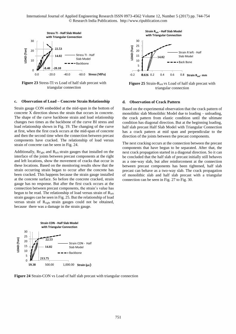
Figure 23 Stress-TI vs Load of half slab precast with
triangular connection
c. Observation of Load – Concrete Strain Relationship
Strain gauge CON embedded at the mid-span in the bottom of
concrete X direction shows the strain that occurs in concrete.
The shape of the curve backbone strain and load relationship
changes two times as the backbone of the curve BI stress and
load relationship shown in Fig. 19. The changing of the curve
at first, when the first crack occurs at the mid-span of concrete
and then the second time when the connection between precast
components have cracked. The relationship of load versus
strain of concrete can be seen in Fig. 24.
Additionally, Rright and Rleft strain gauges that installed on the
interface of the joints between precast components at the right
and left locations, show the movement of cracks that occur in
these locations. Based on the monitoring results show that the
strain occurring strain began to occur after the concrete has
been cracked. This happens because the strain gauge installed
at the concrete surface. So before the concrete cracked, strain
gauge has no response. But after the first crack occurs at the
connection between precast components, the strain’s value has
begun to be read. The relationship of load versus strain of Rleft
strain gauges can be seen in Fig. 25. But the relationship of load
versus strain of Rright strain gauges could not be obtained,
because there was a damage in the strain gauge.
Figure 25 Strain-Rleft vs Load of half slab precast with
triangular connection
d. Observation of Crack Pattern
Based on the experimental observation that the crack pattern of
monolithic slab Monolithic Model due to loading – unloading,
the crack pattern from elastic condition until the ultimate
condition has diagonal direction. But at the beginning loading,
half slab precast Half Slab Model with Triangular Connection
has a crack pattern at mid span and perpendicular to the
direction of the joints between the precast components.
The next cracking occurs at the connection between the precast
components that have begun to be separated. After that, the
next crack propagation started in a diagonal direction. So it can
be concluded that the half slab of precast initially still behaves
as a one-way slab, but after reinforcement at the connection
between precast components has been tightened, half slab
precast can behave as a two-way slab. The crack propagation
of monolithic slab and half slab precast with a triangular
connection can be seen in Fig. 27 to Fig. 30.
Figure 24 Strain-CON vs Load of half slab precast with triangular connection
0
10
20
30
-60.0-40.0-20.00.0
LOA
D (
Ton
)
Stress (MPa)
Stress TI - Half Slab Model with Triangular Connection
Stress TI - HalfSlab Model
Backbone
22.53
-20.10
14.02
-8.40 0
5
10
15
20
25
30
-0.2 0 0.2 0.4 0.6 0.8
LOA
D (
Ton
)
Strain Rleft- mm
Strain Rleft - Half Slab Model with Triangular Connection
Strain R left - HalfSlab Model
Back Bone
14.02
0.026
0
5
10
15
20
25
30
- 500.00 1,000.00
LOA
D (
Ton
)
Strain (me)
Strain CON - Half Slab Model with Triangular Connection
Strain CON - HalfSlab Model
Backbone
59.38
213.75
22.53
14.02

International Journal of Applied Engineering Research ISSN 0973-4562 Volume 12, Number 5 (2017) pp. 744-754
© Research India Publications. http://www.ripublication.com
752
Figure 27 Initial crack of Monolithic and Half Slab Model at crack load
Figure 28 Initial crack of Monolithic and Half Slab Model at crack load
Figure 29 Crack propagation of slab model A and B at 24.54 ton load
Crack propagation
of monolithick
model at 16.53
ton
Crack propagation
of half slab model
at 14.02 ton
Co
nn
ecti
on
Lin
e
Co
nn
ecti
on
Lin
e
Pola Retak Model-A,
Benda Uji-5 pada
Beban Retak Awal
16.53 Ton
Pola Retak Model-B,
Benda Uji-5 pada
Beban Retak Awal
15.02 Ton
First Crack
Connection Line
Load Position
Crack propagation
of monolithic
model at 18.53
ton
Crack propagation
of half slab model
at 18.53 ton
Pola Retak Model-A,
Benda Uji-5 pada
Pembebanan 18.53 Ton
Co
nn
ecti
on
Lin
e
Co
nn
ecti
on
Lin
e
Load Position
Connection Line
Crack propagation
of monolithic
model at 24.54
ton
Crack propagation
of half slab model
at 24.54 ton
Pola Retak Model-A,
Benda Uji-5 pada
Pembebanan 24.54 Ton
Pola Retak Model-C,
Benda Uji-5 pada
Pembebanan 24.54 Ton
Conn
ecti
on
Lin
e
Conn
ecti
on
Lin
e
Load Position
Connection Line

International Journal of Applied Engineering Research ISSN 0973-4562 Volume 12, Number 5 (2017) pp. 744-754
© Research India Publications. http://www.ripublication.com
753
Figure 29 Crack propagation of slab model A and B at 24.54 ton load
CONCLUSION
Base on experimental results, the two-way half slab precast
with a triangular connection has a deflection is higher than the
monolithic slab. The differences is reached 12%. The crack
load of two-way half slab precast with Triangular Connection
has a crack load smaller than a crack load of the monolithic
slab, but not less than 18%.
The reduction of crack load shows not many differences
compared with the model proposed in the preliminary study.
The differences reach 16.5%. However, half slab precast with
triangular connection does not require formwork to be installed
underneath between precast components as required in the
model preliminary study.
The strain of monolithic slab at mid-span X direction has a
strain’s value higher than half slab precast. This happens
because in the half slab precast has a connection between a
precast component in the X direction. So it can be made
reducing the strain in concrete.
The propagation of half slab of precast initially still behaves as
a one-way slab, but after reinforcement at the connection
between precast components has been tightened, half slab
precast can behave as a two-way slab.
The tension reinforcement of half slab precast in X direction
will increase after the initial crack and will increase again after
the connection between precast components has begun to be
separated. So the backbone of the curve that shows relationship
load versus reinforcement stress has three linear shape as
shown in Fig. 19. Because of in Y direction there is no
connection, then the backbone of the curve has a bi-linear shape
as shown in Fig. 17.
The value of stress in compression reinforcement will continue
to increase if the load is increased. But at the certain load,
acceleration of the increasing stress will decrease. This happens
due to the shifting position of the neutral axis is getting to the
top.
REFERENCE
[1] Wijanto and Takim (2008), “State of The Art: Research
and Application of Precast / Prestressed Concrete
Systems in Indonesia”, World Conference on
Earthquake Engineering, Beijing China (2008).
[2] D. Irawan, D. Iranata, P. Suprobo. (2012),
“Experimental Study of Joint Connection Between
Precast Component of Half Slab Precast System (Case
Study of Jetty Slab Structure at Petrokimia
Corporation)”, Research in Structural Laboratory Civil
Engineering Department, Sepuluh Nopember Institute
of Technology.
[3] D.G. Hieber, J.M. Wacker, M.O. Eberhard, J.F. Stanton,
(2005), “State-of-the-Art Report on Precast Concrete
Systems for Rapid Construction of Bridges”, Final
Technical Report Contract T2695, Task 53, Bridge
Rapid Construction, Department of Civil and
Environmental Engineering University of Washington.
[4] D.W. Kim, C.S. Shim, (2014), ”Structural Performance
of Pre-tensioned Half-depth Precast Panels”, Structural
Engineering and Mechanic Journal, Vol.34, Issue 6, pp
1707-1721.
[5] D.W. Kim, C.S. Shim, (2015), ”Crack Width Control on
Concrete Slab using Haf Depth Precast Panels with
Loop Joint”, Structural Engineering and Mechanic
Journal, Vol.35, Issue 1, pp 19-29.
[6] Y. Yardim, (2013), Performance of Precast Thin Panel
as a Permanent Formwork for Precast Composite Slabs.
2nd International Balkans Conference on Challenges of
Civil Engineering, BCCCE, 23-25 May, Epoka
University, Tirana, Albania.
[7] Siswosukarto (2013), “Semi Precast Slab as an
Alternative Method to Promote Green Construction
Residential House Project”, Proceeding the 6th Civil
Pola Retak Model-A,
Benda Uji-5 pada
Pembebanan Akhir
36.56 Ton
Crack propagation
of monolithic
model at 36.56
ton
Crack propagation
of half slab model
at 30.56 ton
Pola Retak Model-C,
Benda Uji-5 pada
Pembebanan Akhir
30.55 Ton
Connection Line
Load Position
Conn
ecti
on
Lin
e
Conn
ecti
on
Lin
e
International Journal of Applied Engineering Research ISSN 0973-4562 Volume 12, Number 5 (2017) pp. 744-754
© Research India Publications. http://www.ripublication.com
754
Engineering Conference, Asia Region: Embracing the
Future through Sustainability ISBN 978-602-8605-08-3.
[8] R.K. Dowell, and R. Auer, (2011),”Flexure-Shear
Behavior of Precast Concrete Deck Panel with Cast-in-
Place Concrete Topping”, PCI Journal, Summer (2011).
[9] P.M.D. Santos, and E.N.B.S. Júlio, (2012), “A state-of-
the-art review on shear-friction”, Journal of
Engineering Structures 45, pp 435–448.
[10] Y.L. Lee, A.T.A. Karim, A.R. Ismail, T.J. Chai, H.B.
Koh, S. Nagapan, D. Yeoh, (2013), “Deflection of
Reinforced Concrete Half Slab”, International Journal
of Construction Technology and Management Vol.1,
No.1, pp 6 – 12.
[11] Vakhsouri, B.(2016), “Time-dependent bond transfer
length under pure tension in one way slab”, Structural
Engineering and Mechanics Journal, Vol 60, No.2, pp
301 – 312.
[12] Tezuka (1994), “Prestressed Half Slab Waffle Slab for
Long-Span Structure”, Shimizu Tech. Res. Bull. No. 13.
[13] I. Moldovan, and A. Mathe, (2015), “A Study on Two -
Way Post-Tensioned Concrete Waffle Slab”,
International Conference Interdisciplinarity in
Engineering, INTER-ENG 8-9, Tirgu - Mures,
Rumania, Published by Elsevier Ltd.
[14] D. Fall, J. Shu, R.R.K. Lundgren, K. Zand, (2014),
“Experimental Investigation of Load Redistributions in
Steel Fibre Reinforced Concrete”, Engineering
Structure Journal, 80, pp 61-74.
[15] J.Y. Kim, M., Jesse, J.M. Longworth, R.G. Wight, and
M.F. Green, (2008),”Flexure of Two-Way Slabs
Strengthened with Prestressed or Non-prestressed CFRP
Sheets”, Journal of Composites for Construction, ASCE
July / August
[16] D. Gouverneur , R.C.L. Taerwe, (2015), “Strain and
Crack Development in Continuous Reinforced Slabs
Subjected to Catenary Action”, Structural Engineering
and Mechanics Journal, Vol 53, No.1, pp 173 – 188.
[17] ACI 437R-03 (2003), “Strength Evaluation of Existing
Concrete Building”, Reported by ACI Committee 437.