Embed Size (px)
Citation preview

ORIGINAL RESEARCH
Experimental study of geotextile as plinth beam in a pilegroup-supported modeled building frame
C. Ravi Kumar Reddy1 • T. D. Gunneswara Rao2
Received: 21 October 2016 / Accepted: 13 September 2017 / Published online: 20 September 2017
� The Author(s) 2017. This article is an open access publication
Abstract This paper presents the experimental results of
static vertical load tests on a model building frame with
geotextile as plinth beam supported by pile groups
embedded in cohesionless soil (sand). The experimental
results have been compared with those obtained from the
nonlinear FEA and conventional method of analysis. The
results revealed that the conventional method of analysis
gives a shear force of about 53%, bending moment at the
top of the column about 17% and at the base of the column
about 50–98% higher than that by the nonlinear FEA for
the frame with geotextile as plinth beam.
Keywords Soil structure interaction � Plinth beam �Geotextile � Pile group � Cohesionless soil � Building frame
Introduction
Soil settlement is a function of the flexural rigidity of the
superstructure. The influence caused by the settlement of
the supporting ground on the response of framed structures
was often ignored in structural design. The structural
stiffness can have a significant influence on the distribution
of the column loads and moments transmitted to the
foundation of the structure. Previous studies have, how-
ever, indicated that the effect of interaction between soil
and structure can be quite significant. Interaction analyses
have been reported in numerous previous studies such as
Meyerhof (1947, 1953), Chamecki (1956), Morris (1966),
Lee and Harrison (1970), Lee and Brown (1972), Subbarao
et al. (and even a few studies in the recent past such as
Deshmukh and Karmarkar (1991), Noorzaei et al. (Noor-
zaei et al. 1995), Srinivasa Rao et al. (1995), Dasgupta
et al. (1998), Mandal et al. (1999), Basack (2008) and
Basack and Purkayastha (2007). The common practice of
obtaining foundation loads from the structural analysis
without allowance for foundation settlement may, there-
fore, result in extra cost that might have been avoided had
the effect of soil–structure interaction been taken into
account in determining the settlements. This requires that
the engineers not only understand the properties of the
ground but they also need to know how the building
responds to deformation and what the consequences of
such deformation will be to the function of the building. In
this regard, many analytical works have been reported on
the building frames founded on pile groups by Buragohain
et al. (1977), Ingle and Chore (2007) and Chore and Ingle
(2008), Chore et al. and the experimental work by Reddy
and Rao (2011). But no significant light was thrown on the
direction of the effect of soil interaction on building frames
with geotextile as plinth beam founded on pile groups.
The aim of this paper is to present an experimental
investigation as well as numerical analysis through the
nonlinear finite element analysis (FEA) of a model plane
frame with geotextile as plinth beam supported by pile
groups embedded in cohesionless soil (sand) under the
static loads (central-concentrated load, uniformly dis-
tributed load (UDL) and eccentric-concentrated load). The
need for consideration of soil interaction in the analysis of
building frame with geotextile as plinth beam is empha-
sized by the experimental investigation by comparing the
behavior of the frame obtained from the experimental and
& C. Ravi Kumar Reddy
1 Department of Civil Engineering, KHIT, Guntur,
A. P 522019, India
2 Department of Civil Engineering, NIT, Warangal 506004,
India
123
Int J Adv Struct Eng (2017) 9:353–363
https://doi.org/10.1007/s40091-017-0171-z

numerical analysis with that by the conventional method of
analysis. An attempt is made to quantify the soil interaction
effect on the response of the building frame in terms of
displacements, rotations, shears and bending moments
through the experimental investigation.
Analytical programme
Analysis programme using ANSYS
The analysis of the model plane frame with geotextile as
plinth beam is carried out using ANSYS for the following
cases:
1. Frame with fixed bases to evaluate the shear force and
bending moment in the column, which is the usual
practice done known as the conventional method.
2. Nonlinear analyses to evaluate the lateral displace-
ments, vertical displacements and rotations, shear
forces and bending moments on the frame.
3. Frame with bases released by imposing the lateral
displacements, vertical displacements and rotations
measured from the experiments for the corresponding
loading on the frame to get the back-figured shear
forces and bending moments generated in the columns.
Nonlinear finite element analysis
The nonlinear analyses were performed for the single-bay
single-storeyed model plane frame with plinth beam founded
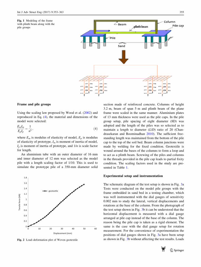
on 2 9 2 pile groups in a sandy soil (Fig. 1). The columns,
beams and piles are modeled using the 3D elastic two-noded
BEAM elements. The pile cap is modeled using the four-
noded elastic SHELL elements. The soil around the indi-
vidual piles was modeled with nonlinear load transfer curves
using the COMBIN39 elements. Geotextile which is used as
plinth beam was also modeled using COMBIN39 elements.
The nonlinear constitutive soil models given by
Eqs. (1)–(3) are employed for the present problem.
The lateral load transfer curves given by Eq. (1) were
used as the API (1987) model,
p ¼ �AsPs tanhkZ�AsPu
y
� �; ð1Þ
where As is the adjustment coefficient for the static p–y
curves,Ps governing ultimate soil resistance, k initial subgrade
reaction constant, Z depth, and Pu ultimate soil resistance.
The axial load transfer curves suggested by McVay et al.
(1989) are used in this study. Also used are the vertical s-Z
springs along the side of the pile as described by the
equation below:
Z ¼ r0s0
Gi
lnðrm � bÞðr0 � bÞ þ
bðrm � r0Þðrm � bÞ � ðr0 � bÞ
� �; ð2Þ
where b = r0s0/sf; r0 is the radius of the pile; s0 shear
stress transferred to the soil for a given Z displacement; rm
radius out from the pile where shear stress is negligible; Gi
initial shear modulus; sf ultimate shear stress at the point of
interest on the pile.
As for the nonlinear tip spring (Q–Z), the following
relation given by the following equation is used:
Z ¼ Qbð1 � mÞ4r0Gi 1 � Qb
Qf
� � ; ð3Þ
where Qf ultimate tip resistance, Gi initial shear modulus, mPoisson’s ratio of the soil, r0 radius of the pile, and Qb
mobilized tip resistance for the given displacement Z.
The following soil properties are used for sand to rep-
resent its resistance in both the lateral and axial directions:
angle of internal friction / (evaluated from the laboratory
experiments), Poisson’s ratio m (a typical value of 0.3 is
used), ultimate skin friction sf (evaluated from Tomlin-
son’s equation), ultimate tip resistance Qf, and shear
modulus Gi (Kulhawy and Mayne 1990). For the analysis
reported herein, the following properties were employed
for the loose sand: angle of internal friction / of 30�, shear
modulus Gi of 9.615 MN/m2, unit weight of soil of 17 kN/
m3 and relative density of 35%.
The frame is loaded with a central-concentrated load,
UDL and eccentric-concentrated load at a nominal eccen-
tricity of 10% of length of the beam (with eccentricity
measured from the center of the beam) in increments as
applied in the experimental program and the response in
terms of deformations, rotations, shear forces and bending
moments is obtained for each load increment.
Experimental program
Geotextile
The wide-width tensile strength test is a popular method to
evaluate properties of various geosynthetics. Various
studies have been conducted by many researchers about the
effects of sample preparation on the test results. However,
it is known that there is no universal relationship between
specimen sizes and test results (Koerner 1998). In this
study, a woven geotextile of 200 mm width by 500 mm
length was chosen for the specimen to satisfy the ASTM
recommendations. The load-deformation property obtained
from the wide-width tensile test is plotted in Fig. 2 which
resembles the behavior reported by Kim and Frost (2005).
354 Int J Adv Struct Eng (2017) 9:353–363
123
Frame and pile groups
Using the scaling law proposed by Wood et al. (2002) and
reproduced in Eq. (4), the material and dimensions of the
model were selected:
EmIm
EpIp¼ 1
n5; ð4Þ
where Em is modulus of elasticity of model, Ep is modulus
of elasticity of prototype, Im is moment of inertia of model,
Ip is moment of inertia of prototype, and 1/n is scale factor
for length.
An aluminium tube with an outer diameter of 16 mm
and inner diameter of 12 mm was selected as the model
pile with a length scaling factor of 1/10. This is used to
simulate the prototype pile of a 350-mm diameter solid
section made of reinforced concrete. Columns of height
3.2 m, beam of span 5 m and plinth beam of the plane
frame were scaled in the same manner. Aluminium plates
of 13 mm thickness were used as the pile caps. In the pile
group setup, pile spacing of eight diameter (8D) was
adopted and the length of the piles was so selected as to
maintain a length to diameter (L/D) ratio of 20 (Chan-
drasekaran and Boominadhan 2010). The sufficient free-
standing length was maintained from the bottom of the pile
cap to the top of the soil bed. Beam column junctions were
made by welding for the fixed condition. Geotextile is
wound around the bases of the columns to form a loop and
to act as a plinth beam. Screwing of the piles and columns
in the threads provided in the pile cap leads to partial fixity
condition. The scaling factors used in the study are pre-
sented in Table 1.
Experimental setup and instrumentation
The schematic diagram of the test setup is shown in Fig. 3a
Tests were conducted on the model pile groups with the
frame embedded in sand bed in a testing chamber, which
was well instrumented with the dial gauges of sensitivity
0.002 mm to study the lateral, vertical displacements and
rotations at the base of the column. From the photograph of
the test setup shown in Fig. 3b it can be understood that the
horizontal displacement is measured with a dial gauge
arranged at pile cap instead of the base of the column. The
reason being the pile cap is taken as a rigid element. The
same is the case with the dial gauge setup for rotation
measurement. For the convenience of experimentation the
positions of dial gauges shown in Fig. 3a have been setup
as shown in Fig. 3b without affecting the test results. Loads
Fig. 1 Modeling of the frame
with plinth beam along with the
pile groups
0
0.2
0.4
0.6
0.8
1
1.2
1.4
1.6
1.8
0 10 20 30 40 50 60
Tensile
force(kN)
Displacement (mm)
geotex�le
Fig. 2 Load–deformation plot of Woven geotextile
Int J Adv Struct Eng (2017) 9:353–363 355
123

on the frame were applied through the hooks provided to
the beam at required locations according to the type of
loads on the beam. The model frame was placed at the
center of the testing chamber using the templates. The sand
is then poured into the testing chamber gently through the
pores of a steel tray in layers to attain the loose state and
uniformity for the sand bed. The installation procedure
simulates the bored pile condition.
Test procedure
Static vertical loads were applied on the model frame
with geotextile as plinth beam by placing weights on the
hangers. The loads were applied in increments and were
maintained for a minimum period to allow the deflec-
tions to stabilize, which means that the short-term
deflections are considered for the analysis and long-term
deflections of soil are neglected. During the application
of static loads, the lateral, vertical displacements at the
base of the column and the rotation of the pile cap were
measured using the instrumentation setup as described
earlier.
Testing phases
Static vertical load tests were conducted on the model
frame with geotextile as plinth beam supported on pile
groups embedded in the sand bed shown in Fig. 3a. Tests
were conducted in the following sequence:
1. Central-concentrated load is applied in increments (1,
2, 3 kg, etc.) at the center of the beam.
2. The beam is loaded at third point with equal loads in
increments (3, 6, 9 kg, etc.) to simulate the uniformly
distributed load (UDL) condition.
3. Eccentric-concentrated load is applied in increments
(1, 2, 3 kg, etc.) at a nominal eccentricity of 10% of the
span of the beam.
Results and discussion
Lateral displacement, settlement and rotation
at the base of the column from the experimental
results and nonlinear FEA
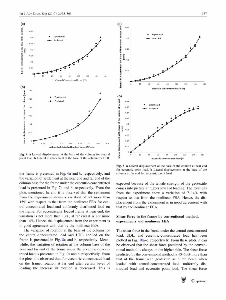
Figure 4a, b represents the variation of the lateral dis-
placement with the static load applied on the frame as
central-concentrated load and uniformly distributed load.
From the plots shown herein, it is observed that the dis-
placement from the experiment shows a variation of not
more than 15% with respect to that from the nonlinear
FEA. Hence, the displacement from the experiment is in
good agreement with that by the nonlinear FEA.
Figure 5a, b represents the variation of the lateral dis-
placement with the static load applied on the frame as
eccentric-concentrated load. From the plots shown herein,
it is observed that the behavior of frame with geotextile as
plinth beam at far end after certain level of loading, the
increase in the lateral displacement is decreased. In case of
frame with geotextile as plinth beam the base of the col-
umn at near end and far end moves outward when the load
applied on the frame is less. As the load on the frame
increases the displacement at far end gets reduces because
of the rigidity of the plinth beam. The displacement from
the experiment shows a variation of not more than 15%
with respect to that from the nonlinear FEA. Hence, the
displacement from the experiment is in good agreement
with that by the nonlinear FEA.
The variation of settlement at the base of the column
with respect to the central-concentrated load and UDL on
Table 1 Scaling factors used in
the studyVariable Length Density Stiffness Stress Strain Force
Scaling factors 1/10 1 1/10 1/10 1 1/103
Fig. 3 a Schematic diagram of the test setup. b Photograph of the test
setup
356 Int J Adv Struct Eng (2017) 9:353–363
123
the frame is presented in Fig. 6a and b, respectively, and
the variation of settlement at the near end and far end of the
column base for the frame under the eccentric-concentrated
load is presented in Fig. 7a and b, respectively. From the
plots mentioned herein, it is observed that the settlement
from the experiment shows a variation of not more than
15% with respect to that from the nonlinear FEA for cen-
tral-concentrated load and uniformly distributed load on
the frame. For eccentrically loaded frame at near end, the
variation is not more than 13%, at far end it is not more
than 14%. Hence, the displacement from the experiment is
in good agreement with that by the nonlinear FEA.
The variation of rotation at the base of the column for
the central-concentrated load and UDL applied on the
frame is presented in Fig. 8a and b, respectively. Mean-
while, the variation of rotation at the column base of the
near and far end of the frame under the eccentric-concen-
trated load is presented in Fig. 9a and b, respectively. From
the plots it is observed that, for eccentric-concentrated load
on the frame, rotation at far end after certain level of
loading the increase in rotation is decreased. This is
expected because of the tensile strength of the geotextile
comes into picture at higher level of loading. The rotations
from the experiment show a variation of 7–14% with
respect to that from the nonlinear FEA. Hence, the dis-
placement from the experiment is in good agreement with
that by the nonlinear FEA.
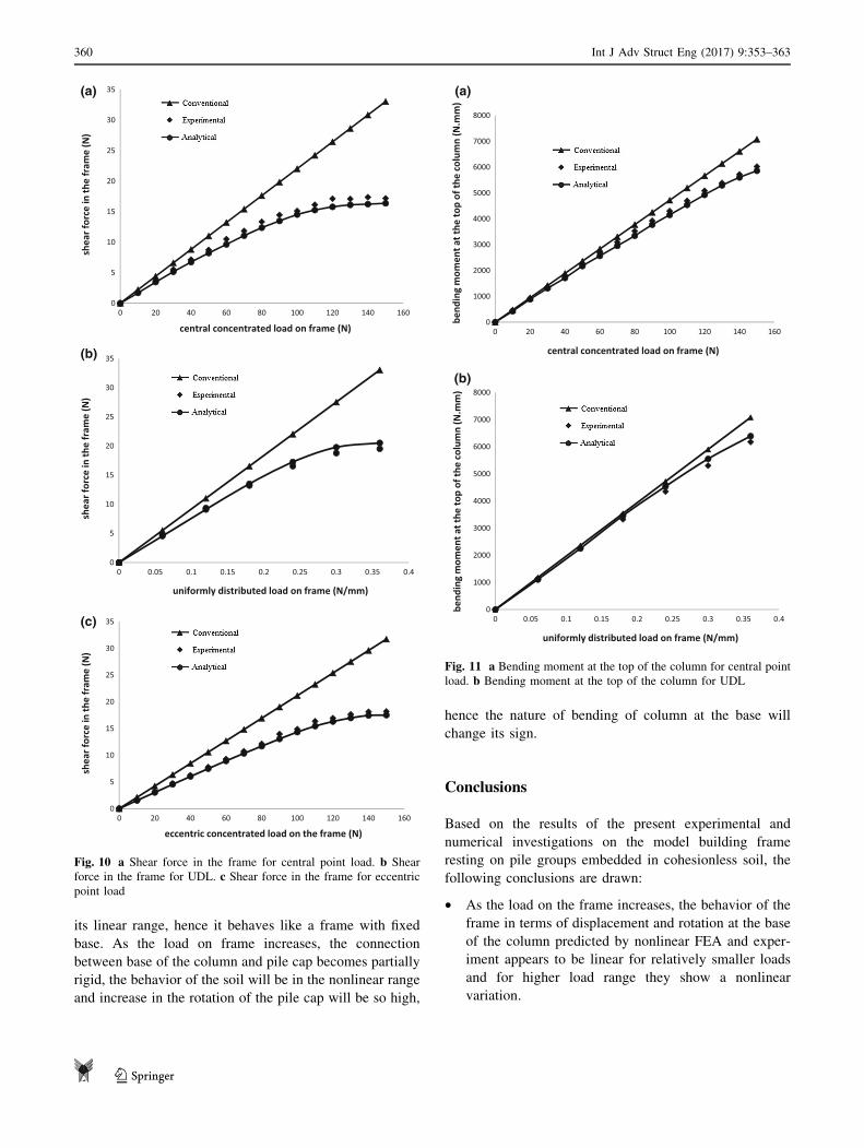
Shear force in the frame by conventional method,
experiments and nonlinear FEA
The shear force in the frame under the central-concentrated
load, UDL, and eccentric-concentrated load has been
plotted in Fig. 10a–c, respectively. From these plots, it can
be observed that the shear force predicted by the conven-
tional method is always on the higher side. The shear force
predicted by the conventional method is 40–50% more than
that of the frame with geotextile as plinth beam when
loaded with central-concentrated load, uniformly dis-
tributed load and eccentric point load. The shear force
0
0.05
0.1
0.15
0.2
0.25
0.3
0.35
0 20 40 60 80 100 120 140 160
Late
ral d
ispl
acem
ent a
t the
bas
e of
the
colu
mn
(mm
)
Central Concentrated Load (N)
0
0.05
0.1
0.15
0.2
0.25
0.3
0 0.05 0.1 0.15 0.2 0.25 0.3 0.35 0.4lateraldisplacem
enta
tthe
base
ofthecolumn(m
m)
uniformly distributed load on frame (N/mm)
(a)
(b)
Fig. 4 a Lateral displacement at the base of the column for central
point load. b Lateral displacement at the base of the column for UDL
0
0.05
0.1
0.15
0.2
0.25
0 20 40 60 80 100 120 140 160
lateraldisplacem
enta
t the
base
ofthecolumnat
near
end
(mm)
eccentric concentrated load (N)
0
0.02
0.04
0.06
0.08
0.1
0.12
0.14
0.16
0.18
0 20 40 60 80 100 120 140 160
lateraldiaplacem
enta
tthe
base
ofthecolumnat
fare
nd(m
m)
eccentric concentrated load (N)
(b)
(a)
Fig. 5 a Lateral displacement at the base of the column at near end
for eccentric point load. b Lateral displacement at the base of the
column at far end for eccentric point load
Int J Adv Struct Eng (2017) 9:353–363 357
123

obtained from the experiment deviates by 8–10% of that
given by the nonlinear FEA, which indicates that the
nonlinear soil model is in good agreement with the
experimental results.
Bending moment at top of the column
by conventional method, experiments and nonlinear
FEA
The bending moment at the top of the column of the
frame under the central-concentrated load and UDL is
plotted in Fig. 11a and b, respectively, and the one of
the near end and far end, respectively, of the frame
under the eccentric load is plotted in Fig. 12a, b. From
the above figures, it is observed that the bending moment
predicted by the conventional method is higher than that
by the other methods of analysis, indicating that the
conventional method of analysis for obtaining the design
moment is uneconomical. When the geotextile is used as
plinth beam the bending moment at top is reduced by
10–17% compared with the conventional method. This
indicates the need for consideration of soil interaction
and use of geotextile as plinth beam in evaluating the
design parameters in a building frame. The values of
bending moment predicted by the nonlinear FEA and
experiments differ by 2–5% only, which indicates that
the nonlinear soil model is well suited for representing
the nonlinear behavior of soil. The point to be noted
with respect to the bending moments at the top of the
column of the frame predicted by different methods is
that though the percentages of variation may not be
great, the differences are significant because the mag-
nitudes of bending moment are of multiples of
thousands.
0
0.2
0.4
0.6
0.8
1
1.2
0 20 40 60 80 100 120 140 160
se�lemen
t atthe
base
ofthecolumn(m
m)
Central Concentrated Load (N)
0
0.2
0.4
0.6
0.8
1
1.2
1.4
0 0.05 0.1 0.15 0.2 0.25 0.3 0.35 0.4
se�lemen
tatthe
base
ofthecolumn(m
m)
Uniformly distributed load on frame (N/mm)
(a)
(b)
Fig. 6 a Settlement at the base of the column for central point load.
b Settlement at the base of the column for UDL
0
0.2
0.4
0.6
0.8
1
1.2
0 20 40 60 80 100 120 140 160
se�lemen
tatthe
base
ofthecolumnat
near
end
(mm)
eccentric concentrated load on the frame (N)
0
0.1
0.2
0.3
0.4
0.5
0.6
0 20 40 60 80 100 120 140 160se�lemen
tatthe
base
ofthecolumnat
fare
nd(m
m)
eccentric concentrated load on the frame (N)
(a)
(b)
Fig. 7 a Settlement at the base of the column at near end for
eccentric point load. b Settlement at the base of the column at far end
for eccentric point load
358 Int J Adv Struct Eng (2017) 9:353–363
123

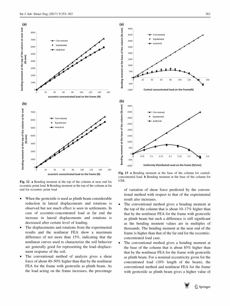
Bending moment at the base of the column
by the conventional method, experiments
and nonlinear FEA
The variation of bending moment at the base of the column
of the frame under the central-concentrated load and UDL
has been plotted in Fig. 13a and b, respectively. Figure 14a
and b shows the variation of bending moment at the base of
the column of the near end and far end, respectively, of the
frame under the eccentric-concentrated load. These fig-
ures show that the conventional method gives a bending
moment 90% higher value than that of the bending moment
of frame with geotextile as plinth beam. Hence, from the
above, it is to be noted that the soil interaction of frame
with geotextile as plinth beam is greatly reducing the
bending moment which will emphasize the need to use the
geotextile as plinth beam.
The bending moments given by the experiments agree
well with those by the nonlinear FEA with a variation of
5–15%. Moreover, the bending moment at the base of the
column changes its sign, when the load reaches some
value. The sign change of the bending moment is observed
to occur at an earlier stage of loading at near end than at
the far end for eccentric-concentrated load. This is due to
the fact that for relatively smaller loads on the frame, the
column is rigidly connected to the pile cap and the soil is in
0
0.01
0.02
0.03
0.04
0.05
0.06
0.07
0.08
0 20 40 60 80 100 120 140 160
rota�o
nat
theba
seof
thecolumn(degrees)
central concentrated load on the frame (N)
0
0.01
0.02
0.03
0.04
0.05
0.06
0.07
0.08
0 0.05 0.1 0.15 0.2 0.25 0.3 0.35 0.4
rota�o
nat
theba
seof
thecolumn(degrees)
uniformly distributed load on the frame (N/mm)
(a)
(b)
Fig. 8 a Rotation at the base of the column for central point load.
b Rotation at the base of the column for UDL
0
0.01
0.02
0.03
0.04
0.05
0.06
0 20 40 60 80 100 120 140 160
rota�o
nat
theba
seof
thecolumnat
near
end(degrees)
eccentric concentrated load on the frame (N)
0
0.005
0.01
0.015
0.02
0.025
0.03
0.035
0.04
0.045
0 20 40 60 80 100 120 140 160rota�o
nat
theba
seof
thecolumnat
fare
nd(degrees)
eccentric concentrated load on the frame (N)
(a)
(b)
Fig. 9 a Rotation at the base of the column at near end for eccentric
point load. b Rotation at the base of the column at far end for
eccentric point load
Int J Adv Struct Eng (2017) 9:353–363 359
123
its linear range, hence it behaves like a frame with fixed
base. As the load on frame increases, the connection
between base of the column and pile cap becomes partially
rigid, the behavior of the soil will be in the nonlinear range
and increase in the rotation of the pile cap will be so high,
hence the nature of bending of column at the base will
change its sign.
Conclusions
Based on the results of the present experimental and
numerical investigations on the model building frame
resting on pile groups embedded in cohesionless soil, the
following conclusions are drawn:
• As the load on the frame increases, the behavior of the
frame in terms of displacement and rotation at the base
of the column predicted by nonlinear FEA and exper-
iment appears to be linear for relatively smaller loads
and for higher load range they show a nonlinear
variation.
0
5
10
15
20
25
30
35
0 20 40 60 80 100 120 140 160
shearforce
inthefram
e(N)
central concentrated load on frame (N)
0
5
10
15
20
25
30
35
0 0.05 0.1 0.15 0.2 0.25 0.3 0.35 0.4
shearforce
inthefram
e(N)
uniformly distributed load on frame (N/mm)
0
5
10
15
20
25
30
35
0 20 40 60 80 100 120 140 160
shearforce
inthefram
e(N)
eccentric concentrated load on the frame (N)
(a)
(b)
(c)
Fig. 10 a Shear force in the frame for central point load. b Shear
force in the frame for UDL. c Shear force in the frame for eccentric
point load
0
1000
2000
3000
4000
5000
6000
7000
8000
0 20 40 60 80 100 120 140 160
bend
ingmom
enta
tthe
topof
thecolumn(N.m
m)
central concentrated load on frame (N)
0
1000
2000
3000
4000
5000
6000
7000
8000
0 0.05 0.1 0.15 0.2 0.25 0.3 0.35 0.4
bend
ingmom
enta
tthe
topof
thecolumn(N.m
m)
uniformly distributed load on frame (N/mm)
(b)
(a)
Fig. 11 a Bending moment at the top of the column for central point
load. b Bending moment at the top of the column for UDL
360 Int J Adv Struct Eng (2017) 9:353–363
123
• When the geotextile is used as plinth beam considerable
reduction in lateral displacements and rotations is
observed but not much effect is seen in settlements. In
case of eccentric-concentrated load at far end the
increase in lateral displacements and rotations is
decreased after certain level of loading.
• The displacements and rotations from the experimental
results and the nonlinear FEA show a maximum
difference of not more than 15%, indicating that the
nonlinear curves used to characterize the soil behavior
are generally good for representing the load–displace-
ment response of the soil.
• The conventional method of analysis gives a shear
force of about 40–50% higher than that by the nonlinear
FEA for the frame with geotextile as plinth beam. As
the load acting on the frame increases, the percentage
of variation of shear force predicted by the conven-
tional method with respect to that of the experimental
result also increases.
• The conventional method gives a bending moment at
the top of the column that is about 10–17% higher than
that by the nonlinear FEA for the frame with geotextile
as plinth beam but such a difference is still significant
as the bending moment values are in multiples of
thousands. The bending moment at the near end of the
frame is higher than that of the far end for the eccentric-
concentrated load case.
• The conventional method gives a bending moment at
the base of the column that is about 85% higher than
that by the nonlinear FEA for the frame with geotextile
as plinth beam. For a nominal eccentricity given for the
concentrated load (10% length of the beam), the
conventional method and nonlinear FEA for the frame
with geotextile as plinth beam gives a higher value of
0
1000
2000
3000
4000
5000
6000
7000
8000
0 20 40 60 80 100 120 140 160
bend
ingmom
enta
tthe
topof
thecolumnat
near
end
(N.m
m)
eccentric concentrated load on the frame (N)
0
1000
2000
3000
4000
5000
6000
7000
0 20 40 60 80 100 120 140 160bend
ingmom
enta
tthe
topof
thecolumnat
far e
nd(N.m
m)
eccentric concentrated load on the frame (N)
(b)
(a)
Fig. 12 a Bending moment at the top of the column at near end for
eccentric point load. b Bending moment at the top of the column at far
end for eccentric point load
1000
500
0
500
1000
1500
2000
2500
3000
3500
4000
0 20 40 60 80 100 120 140 160
Bend
ingmom
enta
tthe
base
ofthecolumn(N.m
m)
Central concentrated load on the frame(N)
1000
500
0
500
1000
1500
2000
2500
3000
3500
4000
0 0.05 0.1 0.15 0.2 0.25 0.3 0.35 0.4
Bend
ingmom
enta
tthe
base
ofthecolumn(N.m
m)
Uniformly Distributed Load on the frame (N/mm)
(b)
(a)
Fig. 13 a Bending moment at the base of the column for central-
concentrated load. b Bending moment at the base of the column for
UDL
Int J Adv Struct Eng (2017) 9:353–363 361
123

bending moment at the column base of the far end from
the load than the one of the near end. The reason behind
this behavior is the displacements and rotations at far
end were reduced when geotextile is used as plinth
beam.
The response of the frame in terms of the design
parameters (i.e., shear and bending moment) from the
conventional method of analysis is always on the higher
side irrespective of the level of loading, which reveals the
need for consideration of the interaction between the
building frame with geotextile as plinth beam, pile foun-
dation, and soil.
Open Access This article is distributed under the terms of the
Creative Commons Attribution 4.0 International License (http://crea
tivecommons.org/licenses/by/4.0/), which permits unrestricted use,
distribution, and reproduction in any medium, provided you give
appropriate credit to the original author(s) and the source, provide a
link to the Creative Commons license, and indicate if changes were
made.
References
American petroleum Institute (1987) Recommended practice for
planning, designing, and constructing fixed offshore platforms,
2A, 17th edn. API Recommended Practice
Basack S (2008) A boundary element analysis of soil–pile interaction
under lateral cyclic loading in soft cohesive soil. Asian J Civ Eng
(Building and Housing) 4(9):377–388
Basack S, Purkayastha RD (2007) Behaviour of single pile under
lateral cyclic load in marine clay. Asian J Civ Eng (Building and
Housing) 4(8):443–458
Buragohain DN, Raghavan N, Chandrasekaran VS (1977) Interaction
of frames with pile foundation. In: Proceedings of International
Symposium on Soil–Structure Interaction, Roorkee, India
Chamecki C (1956) Structural rigidity in calculating settlements.
J Soil Mech Found Div ASCE 82(1):1–19
Chandrasekaran SS, Boominadhan A (2010) Group interaction effects
on laterally loaded piles in clay. J Geotech Geoenviron Eng
ASCE 136:573–582
Chore HS, Ingle RK (2008) Interaction analysis of building frame
supported on pile group. Indian Geotech J 38(4):483–501
Dasgupta S, Dutta SC, Bhattacharya G (1998) Effect of soil–structure
interaction on building frames on isolated footings. J Struct Eng
SERC 26(2):129–134
Deshmukh AM, Karmarkar SR (1991) Interaction of plane frames
with soil. In: Proceedings of Indian Geotechnical Conference
Surat India
Ingle RK, Chore HS (2007) Soil–structure interaction analysis of
building frames-an overview. J Struct Eng SERC
34(5):201–209
Kim D, Frost JD (2005) Multi-scale assessment of geotextile–
geomembrane interaction. In: NAGS 2005/GRI 19 Conference
Las Vegas 8–9
Koerner RM (1998) Designing with geosynthetics. Prince Hall
Fourth, Upper Saddle River, pp 761–762
Kulhawy FH, Mayne PW (1990) Manual on estimating soil properties
for foundation design. EPRI Rep 5(1):5–25
Lee IK, Brown PT (1972) Structures and foundation interaction
analysis. J Struct Div ASCE 11:2413–2431
Lee IK, Harrison HB (1970) Structures and foundation interaction
theory. J Struct Div ASCE 96(2):177–198
Mandal A, Moitra D, Dutta SC (1999) Soil–structure interaction on
building frame: a small scale model study. Int J Struct Roorkee
18(2):92–107
McVay MC, Townsend FC, Bloomquist DG, O’Brien M, Caliendo JA
(1989) Numerical analysis of vertically loaded pile groups. Proc
Found Eng Curr Princ Pract ASCE New York 1:675–690
Meyerhof G (1947) The settlement analysis of building frames. Struct
Eng 25:369–409
Meyerhof G (1953) Some recent foundation research and its
application to design. Struct Eng 31(6):151–167
Morris D (1966) Interaction of continuous frames and soil media.
J Struct Div ASCE 5:13–43
1000
500
0
500
1000
1500
2000
2500
3000
3500
0 20 40 60 80 100 120 140 160
Bend
ingmom
enta
tthe
base
ofthecolumnat
thene
aren
d(N.m
m)
Eccentric concentrated load on the frame (N)
2000
1000
0
1000
2000
3000
4000
0 20 40 60 80 100 120 140 160
Bend
ingmom
enta
tthe
base
ofthecolumnat
thefare
nd(N.m
m)
Eccentric concentrated load on the frame (N)
(a)
(b)
Fig. 14 a Bending moment at the base of the column at near end for
eccentric point load. b Bending moment at the base of the column at
far end for eccentric point load
362 Int J Adv Struct Eng (2017) 9:353–363
123
Noorzaei J, Viladkar MN, Godbole PN (1995) Elasto-plastic analysis
for soil–structure interaction in framed structures. Comput Struct
55(5):797–807
Rao PS, Rambabu KV, Allam MM (1995) Representation of soil
support in analysis of open plane frames. Comput Struct
56:917–925
Ravi KR, Gunneswara R (2011) Experimental study of a modeled
building frame supported by pile groups embedded in cohesion-
less soil. Interact Multiscale Mech 4(4):321–336
Wood DM, Crew A, Taylor C (2002) Shaking table testing of
geotechnical models. Int J Phys Model Geotech 1:1–13
Publisher’s Note
Springer Nature remains neutral with regard to jurisdictional claims in
published maps and institutional affiliations.
Int J Adv Struct Eng (2017) 9:353–363 363
123