Embed Size (px)
Citation preview
EXPERIMENTAL STUDIES ON HEAT TRANSFER AUGMENATATION
USING MODIFIED REDUCED WIDTH TWISTED TAPES (RWTT) AS
INSERTS FOR TUBE SIDE FLOW OF LIQUIDS
A THESIS SUBMITTED IN PARTIAL FULFILLMENT OF THE
REQUIREMENTS FOR THE DEGREE OF
Bachelor of Technology
In
Chemical Engineering
Under the Guidance of
Prof. S.K.Agarwal
By
Gaurav Johar
(10600023)
&
Virendra Hasda
(10600006)
Department of Chemical Engineering
National Institute of Technology
Rourkela
2010
ii
National Institute of Technology, Rourkela
CERTIFICATE
This is to certify that the thesis entitled, “EXPERIMENTAL STUDIES ON HEAT
TRANSFER AUGMENTATION USING MODIFIED REDUCED WIDTH TWISTED
TAPES (RWTT) AS INSERTS FOR TUBE SIDE FLOW OF LIQUIDS” submitted by
Gaurav Johar & Virendra Hasda in partial fulfilments for the requirements for the
award of Bachelor of Technology Degree in Chemical Engineering at National Institute of
Technology, Rourkela (Deemed University) is an authentic work carried out by them under my
supervision and guidance.
To the best of my knowledge, the matter embodied in this thesis has not been submitted
to any other University / Institute for the award of any Degree or Diploma.
Date _____________________
Prof.S.K.Agarwal
Dept .of Chemical Engineering
National Institute of Technology
Rourkela – 769008
iii
ACKNOWLEDGEMENT
We express our deepest appreciation and sincere gratitude to Prof. S. K. Agarwal for his
valuable guidance, constructive crticism and timely suggestions during the entire duration of this
project work, without which this work would not have been possible.
We are also thankful to Prof.H.M.Jena and Prof.R.K.Singh (Project coordinators) for
their valuable guidance.
We would also like to thank Mr S.Majhi, Mr. R.Tirkey & Mr.S.Mohanty (TA) for their
help towards fabrication of twisted tapes.
Date: ___________________
Gaurav Johar
(10600023)
____________________
Virendra Hasda
(10600006)
iv
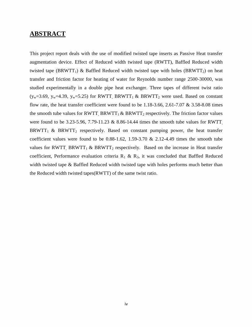
ABSTRACT
This project report deals with the use of modified twisted tape inserts as Passive Heat transfer
augmentation device. Effect of Reduced width twisted tape (RWTT), Baffled Reduced width
twisted tape (BRWTT1) & Baffled Reduced width twisted tape with holes (BRWTT2) on heat
transfer and friction factor for heating of water for Reynolds number range 2500-30000, was
studied experimentally in a double pipe heat exchanger. Three tapes of different twist ratio
(yw=3.69, yw=4.39, yw=5.25) for RWTT, BRWTT1 & BRWTT2 were used. Based on constant
flow rate, the heat transfer coefficient were found to be 1.18-3.66, 2.61-7.07 & 3.58-8.08 times
the smooth tube values for RWTT, BRWTT1 & BRWTT2 respectively. The friction factor values
were found to be 3.23-5.96, 7.79-11.23 & 8.86-14.44 times the smooth tube values for RWTT,
BRWTT1 & BRWTT2 respectively. Based on constant pumping power, the heat transfer
coefficient values were found to be 0.88-1.62, 1.59-3.70 & 2.12-4.49 times the smooth tube
values for RWTT, BRWTT1 & BRWTT2 respectively. Based on the increase in Heat transfer
coefficient, Performance evaluation criteria R1 & R3, it was concluded that Baffled Reduced
width twisted tape & Baffled Reduced width twisted tape with holes performs much better than
the Reduced width twisted tapes(RWTT) of the same twist ratio.

v
CONTENTS
Chapter Topic Page No.
Abstract iv
List of Figures vii
List of Tables viii
Nomenclature ix
Chapter 1 Introduction 1
Chapter 2 Literature Review 3
2.1
Classification of enhancement techniques 4
2.2 Performance Evaluation Criteria 6
2.3 Treated Surfaces 8
2.4 Rough Surfaces 9
2.5 Extended Surfaces 10
2.6 Displacement Enhanced Devices 11
2.7 Swirl Flow Devices 12
2.8 Coiled Tubes 13
2.9 Additives for liquids 14
2.10 Twisted tape in laminar flow 14
2.11 Twisted tape in turbulent flow 19
Chapter 3 Present experimental work 24

vi
3.1 Specifications of Heat exchanger used 25
3.2 Types of inserts used 25
3.3 Fabrication of twisted tapes 27
3.4 Experimental Setup 28
3.5 Experimental Procedure 31
3.6 Standard equations used 33
3.7 Precautions 34
Chapter 4 Sample Calculations 35
4.1 Rotameter Calibration 36
4.2 Pressure drop & Friction factor calculations 36
4.3 Heat transfer coefficient calculation 37
Chapter 5 Results & Discussion 41
5.1 Friction Factor Results 42
5.2 Heat Transfer Coefficient Results 47
5.3 Testing of experimental data for repeatability 51
Chapter 6 Conclusion 52
Chapter 7 Scope for future work 55
References 57
Appendix 62
vii
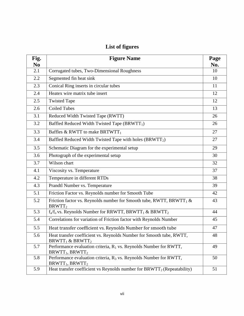
List of figures
Fig.
No
Figure Name Page
No. 2.1 Corrugated tubes, Two-Dimensional Roughness 10
2.2 Segmented fin heat sink 10
2.3 Conical Ring inserts in circular tubes 11
2.4 Heatex wire matrix tube insert 12
2.5 Twisted Tape 12
2.6 Coiled Tubes 13
3.1 Reduced Width Twisted Tape (RWTT) 26
3.2 Baffled Reduced Width Twisted Tape (BRWTT1) 26
3.3 Baffles & RWTT to make BRTWTT1 27
3.4 Baffled Reduced Width Twisted Tape with holes (BRWTT2) 27
3.5 Schematic Diagram for the experimental setup 29
3.6 Photograph of the experimental setup 30
3.7 Wilson chart 32
4.1 Viscosity vs. Temperature 37
4.2 Temperature in different RTDs 38
4.3 Prandtl Number vs. Temperature 39
5.1 Friction Factor vs. Reynolds number for Smooth Tube 42
5.2 Friction factor vs. Reynolds number for Smooth tube, RWTT, BRWTT1 &
BRWTT2
43
5.3 fa/fo vs. Reynolds Number for RRWTT, BRWTT1 & BRWTT2 44
5.4 Correlations for variation of Friction factor with Reynolds Number 45
5.5 Heat transfer coefficient vs. Reynolds Number for smooth tube 47
5.6 Heat transfer coefficient vs. Reynolds Number for Smooth tube, RWTT,
BRWTT1 & BRWTT2
48
5.7 Performance evaluation criteria, R1 vs. Reynolds Number for RWTT,
BRWTT1, BRWTT2
49
5.8 Performance evaluation criteria, R3 vs. Reynolds Number for RWTT,
BRWTT1, BRWTT2
50
5.9 Heat transfer coefficient vs Reynolds number for BRWTT2 (Repeatability) 51
viii
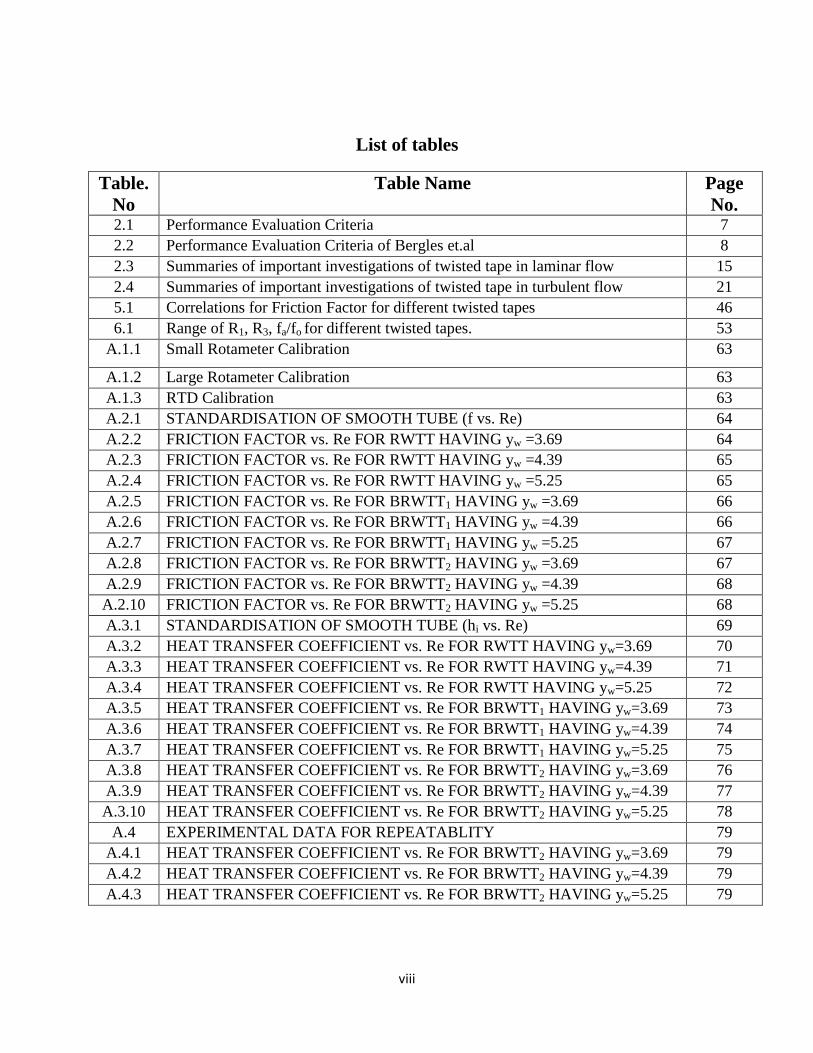
List of tables
Table.
No
Table Name Page
No. 2.1 Performance Evaluation Criteria 7
2.2 Performance Evaluation Criteria of Bergles et.al 8
2.3 Summaries of important investigations of twisted tape in laminar flow 15
2.4 Summaries of important investigations of twisted tape in turbulent flow 21
5.1 Correlations for Friction Factor for different twisted tapes 46
6.1 Range of R1, R3, fa/fo for different twisted tapes. 53
A.1.1 Small Rotameter Calibration 63
A.1.2 Large Rotameter Calibration 63
A.1.3 RTD Calibration 63
A.2.1 STANDARDISATION OF SMOOTH TUBE (f vs. Re) 64
A.2.2 FRICTION FACTOR vs. Re FOR RWTT HAVING yw =3.69 64
A.2.3 FRICTION FACTOR vs. Re FOR RWTT HAVING yw =4.39 65
A.2.4 FRICTION FACTOR vs. Re FOR RWTT HAVING yw =5.25 65
A.2.5 FRICTION FACTOR vs. Re FOR BRWTT1 HAVING yw =3.69 66
A.2.6 FRICTION FACTOR vs. Re FOR BRWTT1 HAVING yw =4.39 66
A.2.7 FRICTION FACTOR vs. Re FOR BRWTT1 HAVING yw =5.25 67
A.2.8 FRICTION FACTOR vs. Re FOR BRWTT2 HAVING yw =3.69 67
A.2.9 FRICTION FACTOR vs. Re FOR BRWTT2 HAVING yw =4.39 68
A.2.10 FRICTION FACTOR vs. Re FOR BRWTT2 HAVING yw =5.25 68
A.3.1 STANDARDISATION OF SMOOTH TUBE (hi vs. Re) 69
A.3.2 HEAT TRANSFER COEFFICIENT vs. Re FOR RWTT HAVING yw=3.69 70
A.3.3 HEAT TRANSFER COEFFICIENT vs. Re FOR RWTT HAVING yw=4.39 71
A.3.4 HEAT TRANSFER COEFFICIENT vs. Re FOR RWTT HAVING yw=5.25 72
A.3.5 HEAT TRANSFER COEFFICIENT vs. Re FOR BRWTT1 HAVING yw=3.69 73
A.3.6 HEAT TRANSFER COEFFICIENT vs. Re FOR BRWTT1 HAVING yw=4.39 74
A.3.7 HEAT TRANSFER COEFFICIENT vs. Re FOR BRWTT1 HAVING yw=5.25 75
A.3.8 HEAT TRANSFER COEFFICIENT vs. Re FOR BRWTT2 HAVING yw=3.69 76
A.3.9 HEAT TRANSFER COEFFICIENT vs. Re FOR BRWTT2 HAVING yw=4.39 77
A.3.10 HEAT TRANSFER COEFFICIENT vs. Re FOR BRWTT2 HAVING yw=5.25 78
A.4 EXPERIMENTAL DATA FOR REPEATABLITY 79
A.4.1 HEAT TRANSFER COEFFICIENT vs. Re FOR BRWTT2 HAVING yw=3.69 79
A.4.2 HEAT TRANSFER COEFFICIENT vs. Re FOR BRWTT2 HAVING yw=4.39 79
A.4.3 HEAT TRANSFER COEFFICIENT vs. Re FOR BRWTT2 HAVING yw=5.25 79
ix
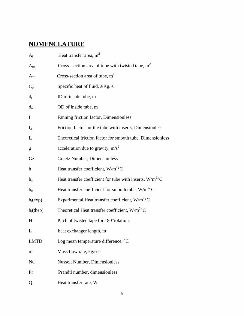
NOMENCLATURE
Ai Heat transfer area, m2
Axa Cross- section area of tube with twisted tape, m2
Axo Cross-section area of tube, m2
Cp Specific heat of fluid, J/Kg.K
di ID of inside tube, m
do OD of inside tube, m
f Fanning friction factor, Dimensionless
fa Friction factor for the tube with inserts, Dimensionless
fo Theoretical friction factor for smooth tube, Dimensionless
g acceleration due to gravity, m/s2
Gz Graetz Number, Dimensionless
h Heat transfer coefficient, W/m2°C
ha Heat transfer coefficient for tube with inserts, W/m2°C
ho Heat transfer coefficient for smooth tube, W/m2°C
hi(exp) Experimental Heat transfer coefficient, W/m2°C
hi(theo) Theoretical Heat transfer coefficient, W/m2°C
H Pitch of twisted tape for 180°rotation,
L heat exchanger length, m
LMTD Log mean temperature difference, °C
m Mass flow rate, kg/sec
Nu Nusselt Number, Dimensionless
Pr Prandtl number, dimensionless
Q Heat transfer rate, W

x
Re Reynolds Number, Dimensionless
R1 Performance evaluation criteria based on constant flow rate, Dimensionless
R3 Performance evaluation criteria based on constant pumping power, Dimensionless
Ui Overall heat transfer coefficient based on inside surface area, W/m2°C
v flow velocity, m/s2
W Width of twisted tape, m
w Width ratio (W/di), Dimensionless
yw Twist ratio of twisted tape (H/W), Dimensionless
Greek letters
∆h Height difference in manometer, m
∆P Pressure difference across heat exchanger, N/m2
µ Viscosity of the fluid, N s/m2
µb Viscosity of fluid at bulk temperature, N s/m2
µw Viscosity of fluid at wall temperature, N s/m2
ρ Density of the fluid, kg/m3

1
CHAPTER 1
INTRODUCTION
2
INTRODUCTION:
Heat exchangers are used in different processes ranging from conversion, utilisation
& recovery of thermal energy in various industrial, commercial & domestic applications.
Some common examples include steam generation & condensation in power & cogeneration
plants; sensible heating & cooling in thermal processing of chemical, pharmaceutical &
agricultural products; fluid heating in manufacturing & waste heat recovery etc. Increase in
Heat exchanger’s performance can lead to more economical design of heat exchanger which
can help to make energy, material & cost savings related to a heat exchange process.
The need to increase the thermal performance of heat exchangers, thereby effecting
energy, material & cost savings have led to development & use of many techniques termed as
―Heat transfer Augmentation‖. These techniques are also referred as ―Heat transfer
Enhancement‖ or ―Intensification‖. Augmentation techniques increase convective heat
transfer by reducing the thermal resistance in a heat exchanger.
Use of Heat transfer enhancement techniques lead to increase in heat transfer
coefficient but at the cost of increase in pressure drop. So, while designing a heat exchanger
using any of these techniques, analysis of heat transfer rate & pressure drop has to be done.
Apart from this, issues like long term performance & detailed economic analysis of heat
exchanger has to be studied. To achieve high heat transfer rate in an existing or new heat
exchanger while taking care of the increased pumping power, several techniques have been
proposed in recent years and are discussed in the following sections.
Twisted tapes-a type of passive heat transfer augmentation techniques have shown
significantly good results in past studies. For experimental work, Reduced width twisted
tapes, having width less than ID of inside tube (W/di=0.727)) are used. Different designs of
twisted tapes used are-Reduced width twisted tapes (RWTT), Baffled reduced width twisted
tapes (BRWTT1) & Baffled reduced width twisted tape with holes (BRWTT2). All these tapes
have been studied with three different twist ratios (yw=3.69, yw=4.39, yw= 5.25)

3
CHAPTER 2
LITERATURE REVIEW
4
2.1 CLASIFICATION OF ENHANCEMENT TECHNIQUES: [1, 2]
Heat transfer enhancement or augmentation techniques refer to the improvement of thermo-
hydraulic performance of heat exchangers. Existing enhancement techniques can be broadly
classified into three different categories:
1. Passive Techniques
2. Active Techniques
3. Compound Techniques.
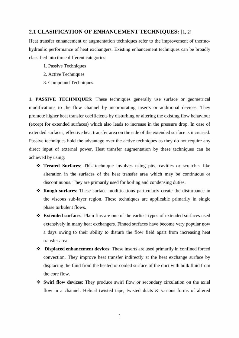
1. PASSIVE TECHNIQUES: These techniques generally use surface or geometrical
modifications to the flow channel by incorporating inserts or additional devices. They
promote higher heat transfer coefficients by disturbing or altering the existing flow behaviour
(except for extended surfaces) which also leads to increase in the pressure drop. In case of
extended surfaces, effective heat transfer area on the side of the extended surface is increased.
Passive techniques hold the advantage over the active techniques as they do not require any
direct input of external power. Heat transfer augmentation by these techniques can be
achieved by using:
Treated Surfaces: This technique involves using pits, cavities or scratches like
alteration in the surfaces of the heat transfer area which may be continuous or
discontinuous. They are primarily used for boiling and condensing duties.
Rough surfaces: These surface modifications particularly create the disturbance in
the viscous sub-layer region. These techniques are applicable primarily in single
phase turbulent flows.
Extended surfaces: Plain fins are one of the earliest types of extended surfaces used
extensively in many heat exchangers. Finned surfaces have become very popular now
a days owing to their ability to disturb the flow field apart from increasing heat
transfer area.
Displaced enhancement devices: These inserts are used primarily in confined forced
convection. They improve heat transfer indirectly at the heat exchange surface by
displacing the fluid from the heated or cooled surface of the duct with bulk fluid from
the core flow.
Swirl flow devices: They produce swirl flow or secondary circulation on the axial
flow in a channel. Helical twisted tape, twisted ducts & various forms of altered
5
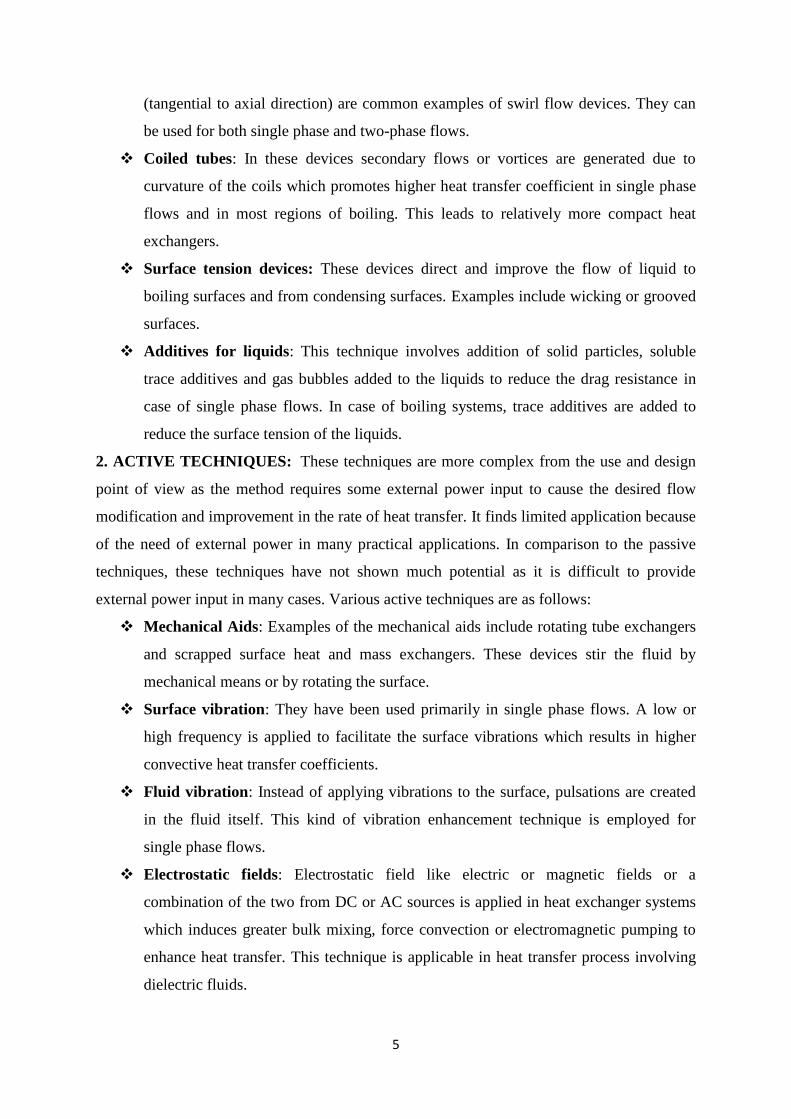
(tangential to axial direction) are common examples of swirl flow devices. They can
be used for both single phase and two-phase flows.
Coiled tubes: In these devices secondary flows or vortices are generated due to
curvature of the coils which promotes higher heat transfer coefficient in single phase
flows and in most regions of boiling. This leads to relatively more compact heat
exchangers.
Surface tension devices: These devices direct and improve the flow of liquid to
boiling surfaces and from condensing surfaces. Examples include wicking or grooved
surfaces.
Additives for liquids: This technique involves addition of solid particles, soluble
trace additives and gas bubbles added to the liquids to reduce the drag resistance in
case of single phase flows. In case of boiling systems, trace additives are added to
reduce the surface tension of the liquids.
2. ACTIVE TECHNIQUES: These techniques are more complex from the use and design
point of view as the method requires some external power input to cause the desired flow
modification and improvement in the rate of heat transfer. It finds limited application because
of the need of external power in many practical applications. In comparison to the passive
techniques, these techniques have not shown much potential as it is difficult to provide
external power input in many cases. Various active techniques are as follows:
Mechanical Aids: Examples of the mechanical aids include rotating tube exchangers
and scrapped surface heat and mass exchangers. These devices stir the fluid by
mechanical means or by rotating the surface.
Surface vibration: They have been used primarily in single phase flows. A low or
high frequency is applied to facilitate the surface vibrations which results in higher
convective heat transfer coefficients.
Fluid vibration: Instead of applying vibrations to the surface, pulsations are created
in the fluid itself. This kind of vibration enhancement technique is employed for
single phase flows.
Electrostatic fields: Electrostatic field like electric or magnetic fields or a
combination of the two from DC or AC sources is applied in heat exchanger systems
which induces greater bulk mixing, force convection or electromagnetic pumping to
enhance heat transfer. This technique is applicable in heat transfer process involving
dielectric fluids.
6
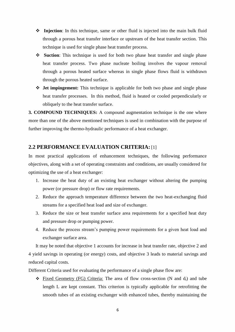
Injection: In this technique, same or other fluid is injected into the main bulk fluid
through a porous heat transfer interface or upstream of the heat transfer section. This
technique is used for single phase heat transfer process.
Suction: This technique is used for both two phase heat transfer and single phase
heat transfer process. Two phase nucleate boiling involves the vapour removal
through a porous heated surface whereas in single phase flows fluid is withdrawn
through the porous heated surface.
Jet impingement: This technique is applicable for both two phase and single phase
heat transfer processes. In this method, fluid is heated or cooled perpendicularly or
obliquely to the heat transfer surface.
3. COMPOUND TECHNIQUES: A compound augmentation technique is the one where
more than one of the above mentioned techniques is used in combination with the purpose of
further improving the thermo-hydraulic performance of a heat exchanger.
2.2 PERFORMANCE EVALUATION CRITERIA: [1]
In most practical applications of enhancement techniques, the following performance
objectives, along with a set of operating constraints and conditions, are usually considered for
optimizing the use of a heat exchanger:
1. Increase the heat duty of an existing heat exchanger without altering the pumping
power (or pressure drop) or flow rate requirements.
2. Reduce the approach temperature difference between the two heat-exchanging fluid
streams for a specified heat load and size of exchanger.
3. Reduce the size or heat transfer surface area requirements for a specified heat duty
and pressure drop or pumping power.
4. Reduce the process stream’s pumping power requirements for a given heat load and
exchanger surface area.
It may be noted that objective 1 accounts for increase in heat transfer rate, objective 2 and
4 yield savings in operating (or energy) costs, and objective 3 leads to material savings and
reduced capital costs.
Different Criteria used for evaluating the performance of a single phase flow are:
Fixed Geometry (FG) Criteria: The area of flow cross-section (N and di) and tube
length L are kept constant. This criterion is typically applicable for retrofitting the
smooth tubes of an existing exchanger with enhanced tubes, thereby maintaining the
7
same basic geometry and size (N, di, L). The objectives then could be to increase the
heat load Q for the same approach temperature ∆Ti and mass flow rate m or pumping
power P; or decrease ∆Ti or P for fixed Q and m or P; or reduce P for fixed Q.
Fixed Number (FN) Criteria - The flow cross sectional area (N and di) is kept
constant, and the heat exchanger length is allowed to vary. Here the objectives are to
seek a reduction in either the heat transfer area (A L) or the pumping power P for a
fixed heat load.
Variable Geometry (VN) Criteria - The flow frontal area (N and L) is kept constant,
but their diameter can change. A heat exchanger is often sized to meet a specified heat
duty Q for a fixed process fluid flow rate m. Because the tube side velocity reduces in
such cases so as to accommodate the higher friction losses in the enhanced surface
tubes, it becomes necessary to increase the flow area to maintain constant m. This is
usually accomplished by using a greater number of parallel flow circuits.
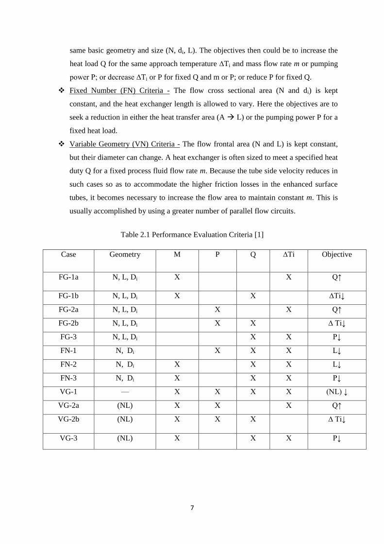
Table 2.1 Performance Evaluation Criteria [1]
Case Geometry M P Q ∆Ti Objective
FG-1a N, L, Di Х Х Q↑
FG-1b N, L, Di Х Х ∆Ti↓
FG-2a N, L, Di Х Х Q↑
FG-2b N, L, Di Х Х ∆ Ti↓
FG-3 N, L, Di Х Х P↓
FN-1 N, Di Х Х Х L↓
FN-2 N, Di Х Х Х L↓
FN-3 N, Di Х Х Х P↓
VG-1 — Х Х Х Х (NL) ↓
VG-2a (NL) Х Х Х Q↑
VG-2b (NL) Х Х Х ∆ Ti↓
VG-3 (NL) Х Х Х P↓
8
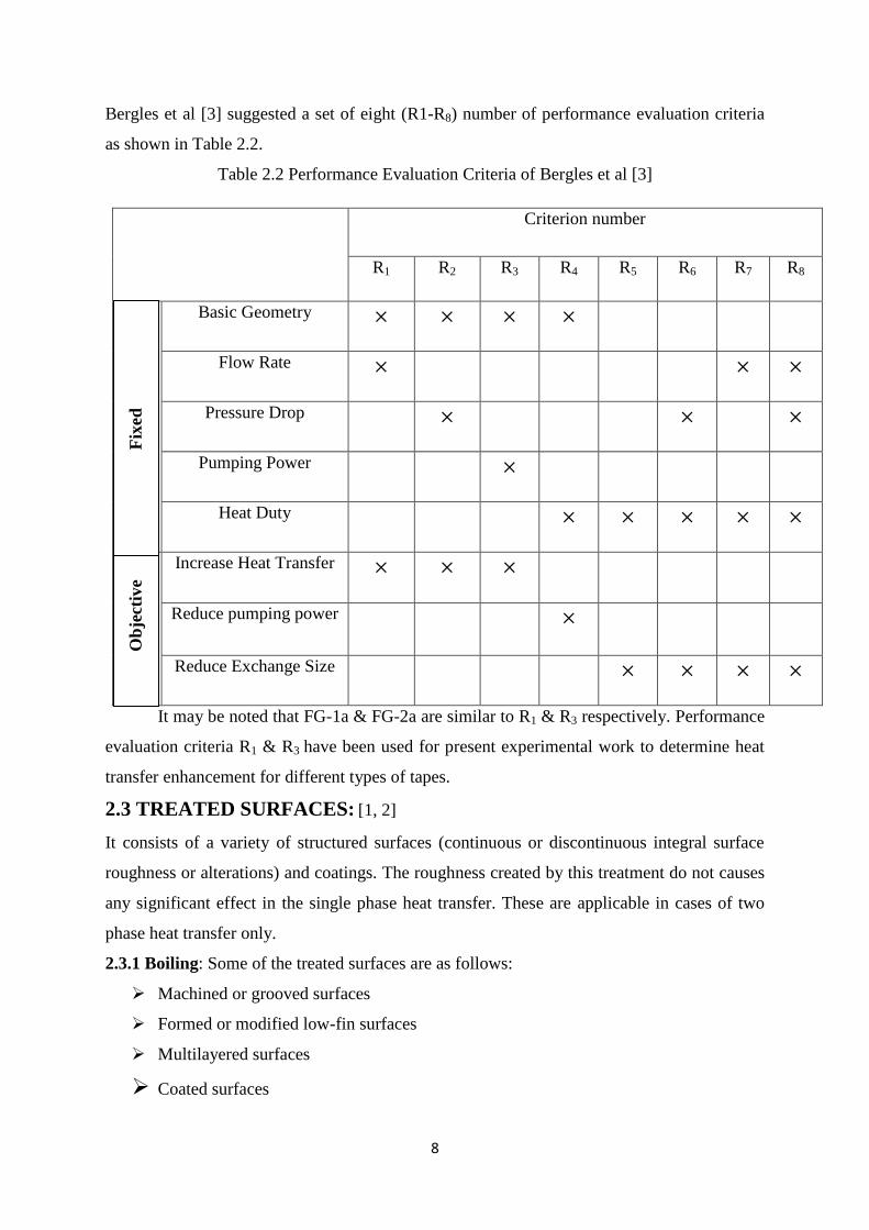
Bergles et al [3] suggested a set of eight (R1-R8) number of performance evaluation criteria
as shown in Table 2.2.
Table 2.2 Performance Evaluation Criteria of Bergles et al [3]
Criterion number
R1 R2 R3 R4 R5 R6 R7 R8
Basic Geometry × × × ×
Flow Rate × × ×
Pressure Drop × × ×
Pumping Power ×
Heat Duty × × × × ×
Increase Heat Transfer × × ×
Reduce pumping power ×
Reduce Exchange Size × × × ×
It may be noted that FG-1a & FG-2a are similar to R1 & R3 respectively. Performance
evaluation criteria R1 & R3 have been used for present experimental work to determine heat
transfer enhancement for different types of tapes.
2.3 TREATED SURFACES: [1, 2]
It consists of a variety of structured surfaces (continuous or discontinuous integral surface
roughness or alterations) and coatings. The roughness created by this treatment do not causes
any significant effect in the single phase heat transfer. These are applicable in cases of two
phase heat transfer only.
2.3.1 Boiling: Some of the treated surfaces are as follows:
Machined or grooved surfaces
Formed or modified low-fin surfaces
Multilayered surfaces
Coated surfaces
F
ixed
O
bje
ctiv
e
9
In enhanced boiling treated surfaces provide a large number of stable vapour traps or
nucleation sites on the surface for bubble formation. In case of highly wetting fluids like
refrigerants, organic liquids, cryogens and alkali liquid metals the normal cavities present on
the heated surfaces tend to experience sub-cooled liquid flooding. For high surface tension
fluids, coatings of non-wetting material (e.g. Teflon) on either the heated surface or its pits
and cavities were found to be effective in nucleate boiling. Stainless steel surface along with
Teflon can be spread to create spots of the no-wetting material on the heated surface which
results in three to four times higher heat transfer coefficients.
2.3.2 Condensing: In condensation of vapours, treated surfaces promote drop wise
condensation which is ideal for preventing surface wetting and break up the condensate film
into droplets. This process provides better drainage and more effective vapour removal at
cold heat transfer interface. This technique increases heat transfer by a factor of 10 to 100 in
drop wise condensation when compared with that in film wise condensation as proposed by
Bergles. Non- wetting inorganic compound or a noble metals or an organic polymer can be
used effectively for coating the heat transfer surfaces. Among these, organic coatings have
been used considerably in steam systems.
2.4 ROUGH SURFACES: [1, 2]
Small scale roughness or surface modification promotes turbulence in the flow field near the
wall region by disturbing the viscous laminar sub layer. This disturbance causes higher
momentum and heart transfer. This small scale roughness has little effect in laminar flows,
but is very effective in turbulent single phase flows. Nowadays instead of natural roughness,
artificial and structured roughness is used in most applications. Structured roughness can be
integral to the surface. Wire coil type inserts can be inserted inside the tube to provide
protuberances in the surface. In case of structured roughness almost an infinite number of
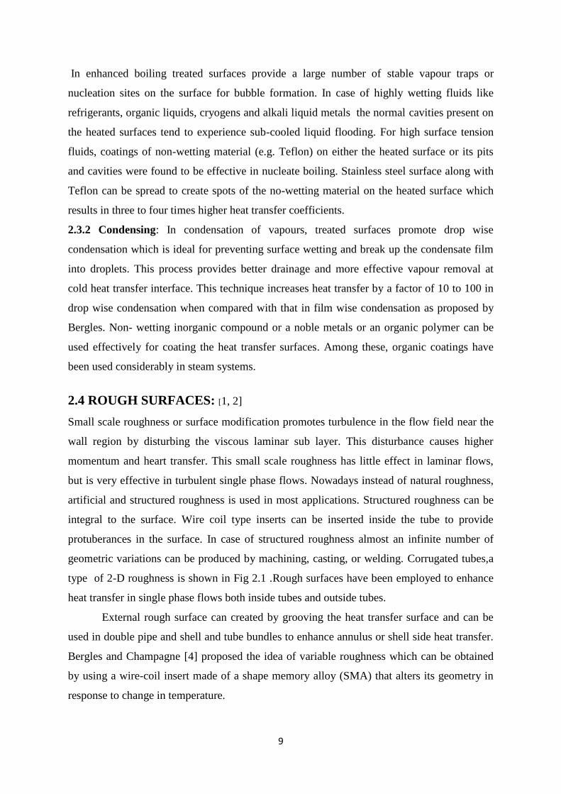
geometric variations can be produced by machining, casting, or welding. Corrugated tubes,a
type of 2-D roughness is shown in Fig 2.1 .Rough surfaces have been employed to enhance
heat transfer in single phase flows both inside tubes and outside tubes.
External rough surface can created by grooving the heat transfer surface and can be
used in double pipe and shell and tube bundles to enhance annulus or shell side heat transfer.
Bergles and Champagne [4] proposed the idea of variable roughness which can be obtained
by using a wire-coil insert made of a shape memory alloy (SMA) that alters its geometry in
response to change in temperature.
10
Fig. 2.1: Corrugated tubes, Two-Dimensional Roughness
2.5 EXTENDED SURFACES: [1, 2]
Extended or finned surfaces increase the heat transfer area which could be very
effective in case of fluids with low heat transfer coefficients. This technique includes finned
tube for shell & tube exchangers, plate fins for compact heat exchanger and finned heat sinks
for electronic cooling.
Finned surfaces enhance heat transfer in natural or forced convection which can be used for
cooling of electrical and electronic devices. The use of extended surfaces for cooling
electronic devices is not restricted to the natural convection heat transfer regime but also can
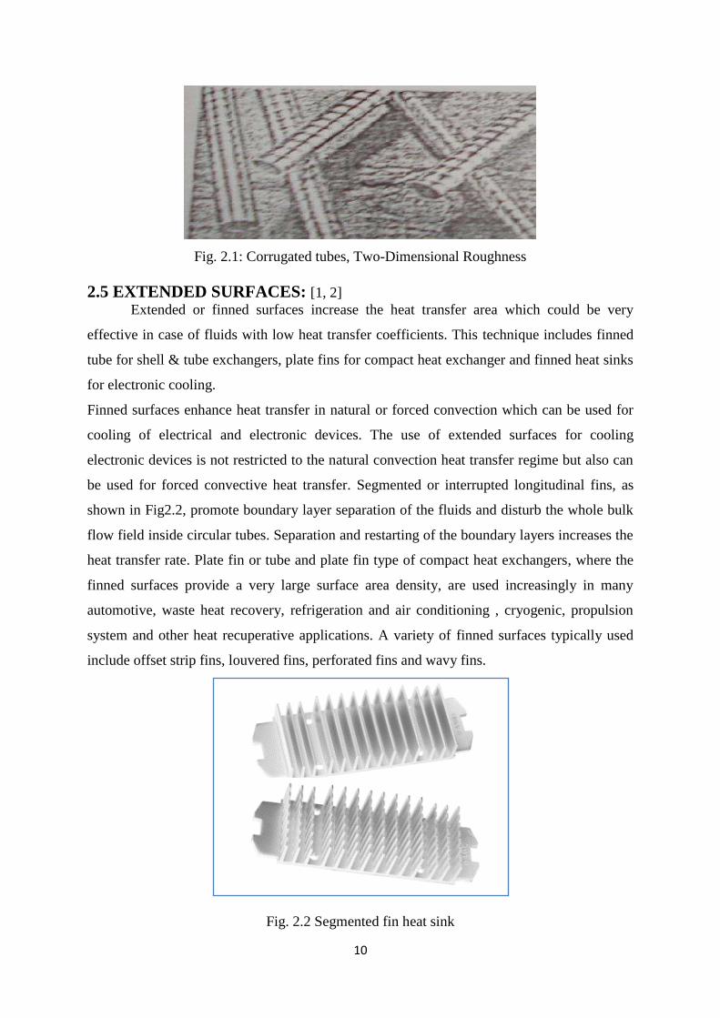
be used for forced convective heat transfer. Segmented or interrupted longitudinal fins, as
shown in Fig2.2, promote boundary layer separation of the fluids and disturb the whole bulk
flow field inside circular tubes. Separation and restarting of the boundary layers increases the
heat transfer rate. Plate fin or tube and plate fin type of compact heat exchangers, where the
finned surfaces provide a very large surface area density, are used increasingly in many
automotive, waste heat recovery, refrigeration and air conditioning , cryogenic, propulsion
system and other heat recuperative applications. A variety of finned surfaces typically used
include offset strip fins, louvered fins, perforated fins and wavy fins.
Fig. 2.2 Segmented fin heat sink
11
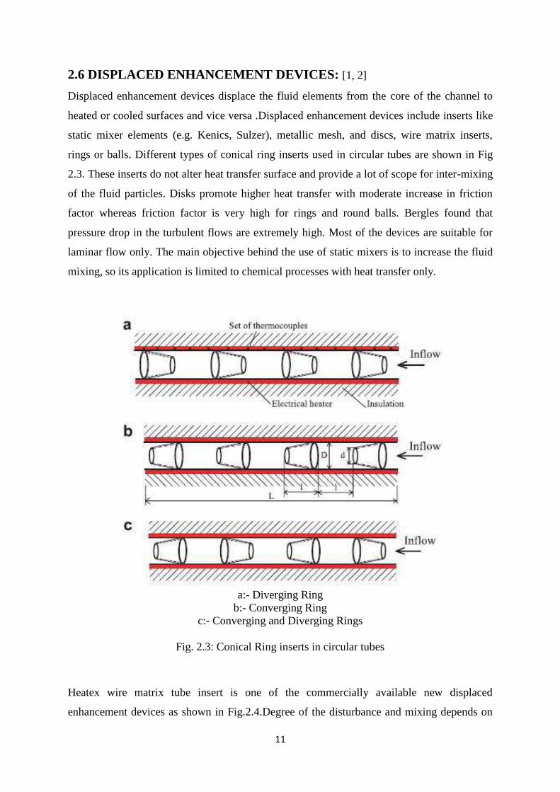
2.6 DISPLACED ENHANCEMENT DEVICES: [1, 2]
Displaced enhancement devices displace the fluid elements from the core of the channel to
heated or cooled surfaces and vice versa .Displaced enhancement devices include inserts like
static mixer elements (e.g. Kenics, Sulzer), metallic mesh, and discs, wire matrix inserts,
rings or balls. Different types of conical ring inserts used in circular tubes are shown in Fig
2.3. These inserts do not alter heat transfer surface and provide a lot of scope for inter-mixing
of the fluid particles. Disks promote higher heat transfer with moderate increase in friction
factor whereas friction factor is very high for rings and round balls. Bergles found that
pressure drop in the turbulent flows are extremely high. Most of the devices are suitable for
laminar flow only. The main objective behind the use of static mixers is to increase the fluid
mixing, so its application is limited to chemical processes with heat transfer only.
a:- Diverging Ring
b:- Converging Ring
c:- Converging and Diverging Rings
Fig. 2.3: Conical Ring inserts in circular tubes
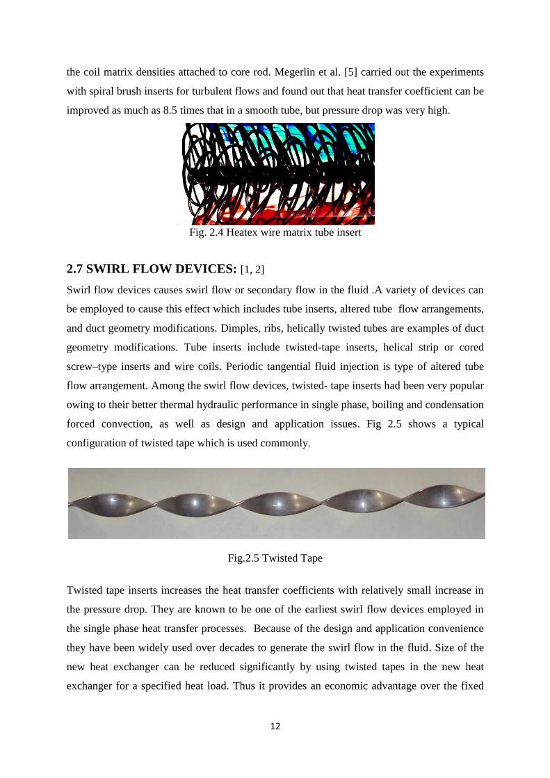
Heatex wire matrix tube insert is one of the commercially available new displaced
enhancement devices as shown in Fig.2.4.Degree of the disturbance and mixing depends on
12
the coil matrix densities attached to core rod. Megerlin et al. [5] carried out the experiments
with spiral brush inserts for turbulent flows and found out that heat transfer coefficient can be
improved as much as 8.5 times that in a smooth tube, but pressure drop was very high.
Fig. 2.4 Heatex wire matrix tube insert
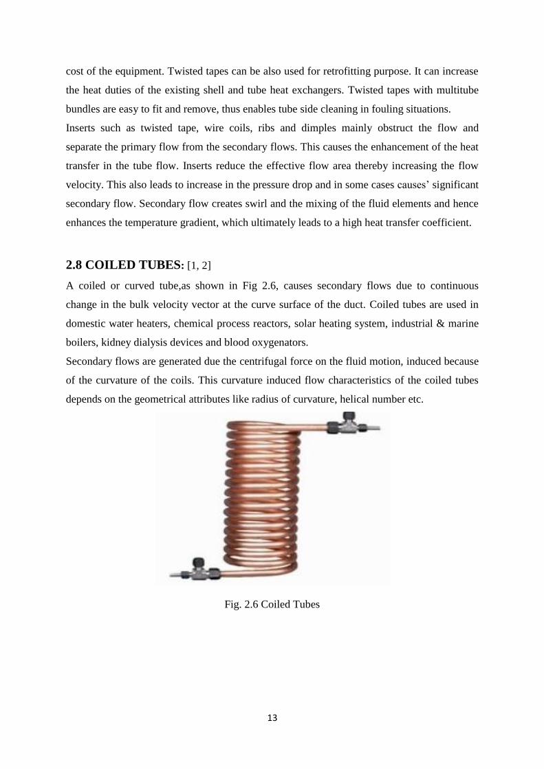
2.7 SWIRL FLOW DEVICES: [1, 2]
Swirl flow devices causes swirl flow or secondary flow in the fluid .A variety of devices can
be employed to cause this effect which includes tube inserts, altered tube flow arrangements,
and duct geometry modifications. Dimples, ribs, helically twisted tubes are examples of duct
geometry modifications. Tube inserts include twisted-tape inserts, helical strip or cored
screw–type inserts and wire coils. Periodic tangential fluid injection is type of altered tube
flow arrangement. Among the swirl flow devices, twisted- tape inserts had been very popular
owing to their better thermal hydraulic performance in single phase, boiling and condensation
forced convection, as well as design and application issues. Fig 2.5 shows a typical
configuration of twisted tape which is used commonly.
Fig.2.5 Twisted Tape
Twisted tape inserts increases the heat transfer coefficients with relatively small increase in
the pressure drop. They are known to be one of the earliest swirl flow devices employed in
the single phase heat transfer processes. Because of the design and application convenience
they have been widely used over decades to generate the swirl flow in the fluid. Size of the
new heat exchanger can be reduced significantly by using twisted tapes in the new heat
exchanger for a specified heat load. Thus it provides an economic advantage over the fixed
13
cost of the equipment. Twisted tapes can be also used for retrofitting purpose. It can increase
the heat duties of the existing shell and tube heat exchangers. Twisted tapes with multitube
bundles are easy to fit and remove, thus enables tube side cleaning in fouling situations.
Inserts such as twisted tape, wire coils, ribs and dimples mainly obstruct the flow and
separate the primary flow from the secondary flows. This causes the enhancement of the heat
transfer in the tube flow. Inserts reduce the effective flow area thereby increasing the flow
velocity. This also leads to increase in the pressure drop and in some cases causes’ significant
secondary flow. Secondary flow creates swirl and the mixing of the fluid elements and hence
enhances the temperature gradient, which ultimately leads to a high heat transfer coefficient.
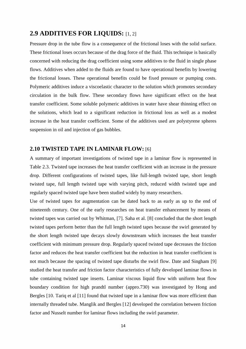
2.8 COILED TUBES: [1, 2] A coiled or curved tube,as shown in Fig 2.6, causes secondary flows due to continuous
change in the bulk velocity vector at the curve surface of the duct. Coiled tubes are used in
domestic water heaters, chemical process reactors, solar heating system, industrial & marine
boilers, kidney dialysis devices and blood oxygenators.
Secondary flows are generated due the centrifugal force on the fluid motion, induced because
of the curvature of the coils. This curvature induced flow characteristics of the coiled tubes
depends on the geometrical attributes like radius of curvature, helical number etc.
Fig. 2.6 Coiled Tubes
14
2.9 ADDITIVES FOR LIQUIDS: [1, 2]
Pressure drop in the tube flow is a consequence of the frictional loses with the solid surface.
These frictional loses occurs because of the drag force of the fluid. This technique is basically
concerned with reducing the drag coefficient using some additives to the fluid in single phase
flows. Additives when added to the fluids are found to have operational benefits by lowering
the frictional losses. These operational benefits could be fixed pressure or pumping costs.
Polymeric additives induce a viscoelastic character to the solution which promotes secondary
circulation in the bulk flow. These secondary flows have significant effect on the heat
transfer coefficient. Some soluble polymeric additives in water have shear thinning effect on
the solutions, which lead to a significant reduction in frictional loss as well as a modest
increase in the heat transfer coefficient. Some of the additives used are polystyrene spheres
suspension in oil and injection of gas bubbles.
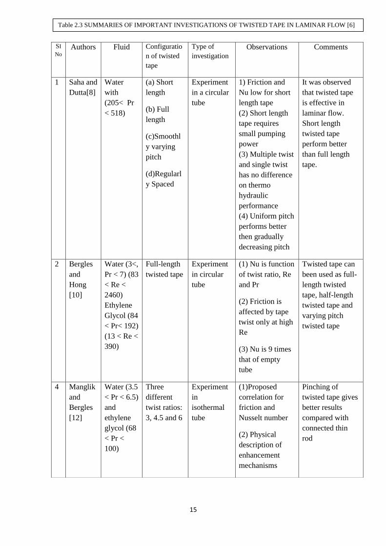
2.10 TWISTED TAPE IN LAMINAR FLOW: [6]
A summary of important investigations of twisted tape in a laminar flow is represented in
Table 2.3. Twisted tape increases the heat transfer coefficient with an increase in the pressure
drop. Different configurations of twisted tapes, like full-length twisted tape, short length
twisted tape, full length twisted tape with varying pitch, reduced width twisted tape and
regularly spaced twisted tape have been studied widely by many researchers.
Use of twisted tapes for augmentation can be dated back to as early as up to the end of
nineteenth century. One of the early researches on heat transfer enhancement by means of
twisted tapes was carried out by Whitman, [7]. Saha et al. [8] concluded that the short length
twisted tapes perform better than the full length twisted tapes because the swirl generated by
the short length twisted tape decays slowly downstream which increases the heat transfer
coefficient with minimum pressure drop. Regularly spaced twisted tape decreases the friction
factor and reduces the heat transfer coefficient but the reduction in heat transfer coefficient is
not much because the spacing of twisted tape disturbs the swirl flow. Date and Singham [9]
studied the heat transfer and friction factor characteristics of fully developed laminar flows in
tube containing twisted tape inserts. Laminar viscous liquid flow with uniform heat flow
boundary condition for high prandtl number (appro.730) was investigated by Hong and
Bergles [10. Tariq et al [11] found that twisted tape in a laminar flow was more efficient than
internally threaded tube. Manglik and Bergles [12] developed the correlation between friction
factor and Nusselt number for laminar flows including the swirl parameter.
15
SI
No Authors Fluid Configuratio
n of twisted
tape
Type of
investigation Observations Comments
1 Saha and
Dutta[8]
Water
with
(205< Pr
< 518)
(a) Short
length
(b) Full
length
(c)Smoothl
y varying
pitch
(d)Regularl
y Spaced
Experiment
in a circular
tube
1) Friction and
Nu low for short
length tape
(2) Short length
tape requires
small pumping
power
(3) Multiple twist
and single twist
has no difference
on thermo
hydraulic
performance
(4) Uniform pitch
performs better
then gradually
decreasing pitch
It was observed
that twisted tape
is effective in
laminar flow.
Short length
twisted tape
perform better
than full length
tape.
2 Bergles
and
Hong
[10]
Water (3<,
Pr < 7) (83
< Re <
2460)
Ethylene
Glycol (84
< Pr< 192)
(13 < Re <
390)
Full-length
twisted tape
Experiment
in circular
tube
(1) Nu is function
of twist ratio, Re
and Pr
(2) Friction is
affected by tape
twist only at high
Re
(3) Nu is 9 times
that of empty
tube
Twisted tape can
been used as full-
length twisted
tape, half-length
twisted tape and
varying pitch
twisted tape
4 Manglik
and
Bergles
[12]
Water (3.5
< Pr < 6.5)
and
ethylene
glycol (68
< Pr <
100)
Three
different
twist ratios:
3, 4.5 and 6
Experiment
in
isothermal
tube
(1)Proposed
correlation for
friction and
Nusselt number
(2) Physical
description of
enhancement
mechanisms
Pinching of
twisted tape gives
better results
compared with
connected thin
rod
Table 2.3 SUMMARIES OF IMPORTANT INVESTIGATIONS OF TWISTED TAPE IN LAMINAR FLOW [6]

16
5 Saha et
al. [13]
Fluids
with 205 <
Pr<518
Twisted
tape
(regularly
spaced)
Experiment
in circular
tube
(1) Pinching of
twisted tape gives
better results than
connecting thin
rod for thermo
hydraulic
performance
(2) Reducing tape
width gives poor
results; larger
than zero phase
angle not
effective
6 Lokanat
h and
Misal
[14]
Water (3 <
Pr <6.5
and lube
oil (Pr
418)
Twisted
tape
Experiment
in plate heat
exchanger
and shell
and tube
heat
exchanger
(1) Large value
of overall heat
transfer
coefficient
produced in
water-to water
mode with oil-to
water mode
7 Lokanat
h [15]
Water
(240 < Re
< 2300)
(2.6 < Pr <
5.4)
Full-length
and half-
length
twisted
tapes
Experimenta
l in
horizontal
tube
(1) On unit
pressure drop
basis and on unit
pumping power
basis, half-length
twisted tape is
more effective
than full-length
twisted tape
8 Liao and
Xin[17]
(1) Water
(2)
Ethylene
glycol
(3)
Turbine
oil 5.5 <
Pr < 590,
80 < Re<
50000
Segmented
twisted tape
and three-
dimensional
extended
surfaces
Experiment
in tube flow
(1) In a tube with
three-dimensional
Extended
surfaces and
twisted tape
increases average
Stanton number
up to 5.8 times
compared with
empty smooth
tube
17
9 Ujhidy
[18]
Water Twisted
tape
Experiment
in channel
(1) Explained
flow structure
(2) Proved
existence of
secondary flow in
tubes with helical
static elements.
10 Suresh
Kumar
[19]
Water Twisted
tape
Experiment
in large
diameter
annulus
(1) Observed
relatively large
values of friction
factor
(2) Measured
heat transfer in
annulus with
different
configurations of
twisted tapes
11 Saha and Chakrabort
y [20]
Water
(145 <
Re<1480)
(4.5 < Pr <
5.5)
Twisted
tape
(regularly
spaced)
(1.92<y<5.0
)
Experiment
in circular
tube flow
(1) Larger
number of turns
may yield
improved thermo
hydraulic
performance
compared with
single turn
12 Saha and
Bhunia
[22]
Servotherm
medium
oil (205 <
Pr <
512,45<
Re < 840)
Twisted
tape (twist
ratio 2.5<y
<10)
Experiment
in circular
tube
(1) Heat transfer
characteristics
depend on twist
ratio, Re and Pr
Uniform pitch
twisted tape
performs better
than gradually
varying pitch
twisted tape
13 Agarwal
and Raja
Rao[23]
Servotherm
oil Twisted
tape
Experiment
in circular
tube
Nusselt number
for augmented
tube is more than
plain tube
18
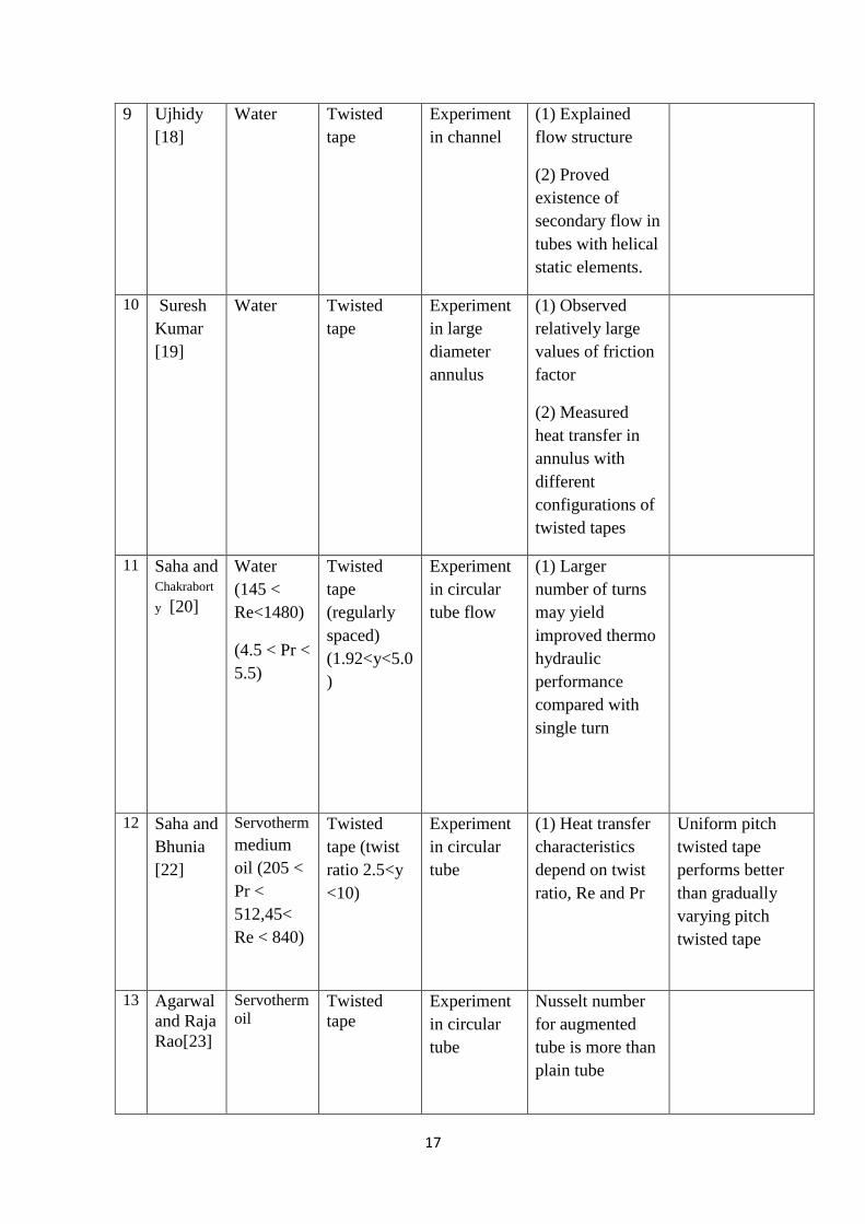
Saha et al. [13] found that placing twisted tape concentric to the inside tube gives
better heat transfer performance than a twisted tape inserted by a loose fit. Lokanath and
Misal [14] studied twisted tapes in shell and tube heat exchanger for different fluids. Their
study revealed that twisted tapes of tighter twists are expected to give higher overall heat
transfer coefficients. Lokanath [15] investigated the laminar flow experimentally using the
tube fitted with half length tapes. He concluded that half length twisted tapes gives better
performance than full length twisted tapes on the basis of unit pumping power
AI-Fahed et al. [16] investigated that , for high pressure drop and low twist ratio (y = 5.4)
and, a loose fit twisted tape is a better option for the heat exchanger owing to it’s easy
installation and removal for cleaning purposes. For other twist ratios tight fit gives better
performance that the loose- fit twisted tapes. Liao and Xin [17] carried out experimental work
on compound heat transfer enhancement technique with three dimensional internal extended
surfaces by using segmented twisted tape inserts. Results revealed the reduction in the
friction factor with small decrease in Stanton number. The Stanton number is the ratio of heat
transfer rate to the enthalpy difference and gives a measure of the heat transfer coefficient.
Ujhidy et al. [18] proposed a modified dean number for the laminar flow in coils and tubes
containing twisted tapes and helical elements. Dean number compensates for the curvature of
the coiled tubes or helical elements and gives the measure of the magnitude of the secondary
flows. Thermo-hydraulic performance of twisted tape inserts in a large hydraulic diameter
annulus was reported by Suresh Kumar et al., [19].
In laminar flow, the dominant thermal resistance is distributed entirely over the cross section
of the tube. Thus, a twisted tape insert is more effective than other technique as it mixes the
bulk flow.
Saha and Chakraborty [20] observed the drastic reduction in the pressure drop compared to
the reduction in the heat transfer in their experiment carried out with regularly spaced twisted
tapes for laminar flow conditions. It was concluded that for a constant pumping power a large
number of turns gives a better thermo-hydraulic performance than the single turn in the
twisted tapes.
P.Sivashanmugam and S.Suresh [21] investigated heat transfer and friction factor
characteristics of circular tube fitted with full length helical screw elements of different twist
ratio and helical screw inserts with spacer length 100,200,300,400 mm with uniform heat flux
under laminar flow conditions. They found that regularly spaced helical screw elements can
safely be used for heat transfer augmentation without much increase in pressure drop than full
length helical screw inserts. S.K.Agarwal and M.Raja Rao [23] experimentally determined
19
the isothermal and non-isothermal friction factors and mean Nusselt Numbers for uniform
wall temperature heating and cooling of Servotherm oil for flow in a circular tube with
twisted tape insert.
2.11 TWISTED TAPE IN TURBULENT FLOW: [6]
Unlike laminar flows where thermal resistance exist entirely over the cross section, it is
limited to the thin viscous sub layer. So the main objective of the twisted tape in the turbulent
region is to reduce that resistance near the wall to promote better heat transfer. Besides, a
tube inserted with a twisted tape produces swirl and cause intermixing of the fluid which
leads to better performance than a plain tube. Heat transfer rate is improved effectively with
the increase in the frictional losses. A summary of important investigations of twisted tape in
turbulent flow is represented in Table 2.4.
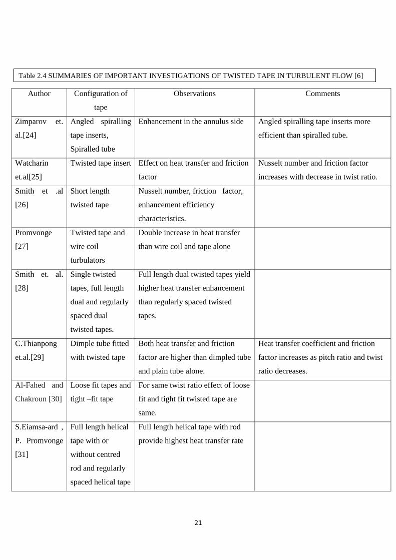
Ventisislav D.Zimparov, Plamen J.Penchev and Joshua P. Meyer [24] evaluated the
performance of angled spiralling tape inserts, a round tube inside a twisted square tube and
spiralled tube inside the annulus for enhancement in the annulus side of tube-in-tube Heat
exchanger. The results showed that for most of the cases, angled spiralling tube inserts
technique is the most efficient. Watcharin Noothong, Smith Eiamsa-ard and Pongjet
Promvonge [25] studied experimentally the effect of twisted tape insert on heat transfer and
friction factor characteristics in concentric tube heat exchanger for Reynolds number 2000 to
12000. They found that enhancement efficiency and Nusselt number increases with
decreasing the twist ratio and friction factor also increase with decreasing the twist ratio.
Smith et. al [26] carried out experimental study on the mean Nusselt number; friction factor
and enhancement efficiency characteristics in a round tube with short-length twisted tape
insert under uniform wall heat flux boundary conditions for Re 4000 to 20000. Pongjet
Promvonge [27] examined the thermal augmentation in a circular tube with twisted tape and
wire coil turbulators for Reynolds Number 3000 to 18000.The report indicate that presence of
wire coils together with the twisted tape lead to double increase in the heat transfer over the
use of wire coil or twisted tape alone. Smith et. al. [28] investigated the heat transfer
enhancement and pressure loss by insertion of single twisted tape, full length dual and
regularly spaced dual twisted tapes as swirl generators in round tube under axially uniform
wall heat flux conditions. Chinaruk Thianpong et.al. [29] experimentally investigated the
friction and compound heat transfer behavior in dimpled tube fitted with twisted tape swirl
generator for a fully developed flow for Reynolds number in the range of 12000 to 44000.
20
Al-Fahed and Chakroun [30] studied the effect of tube -tape clearance for a fully developed
turbulent flow in an isothermal condition. Their results revealed that for low twist ratio loose
fit tape shows nearly the same enhancement as the tight-fit of the twist ratio. Such behavior
indicates the presence of an optimum tape width. Smith Eiamsa-ard and Pongjet Promvonge
[31] carried out the experiments with full length helical tape with or without centered rod and
regularly spaced helical tube.
T.S.Ravigururajan and A.E.Bergles [32] developed the correlations for pressure drop and
heat transfer in single phase turbulent flow in enhanced tubes. Results were found to be
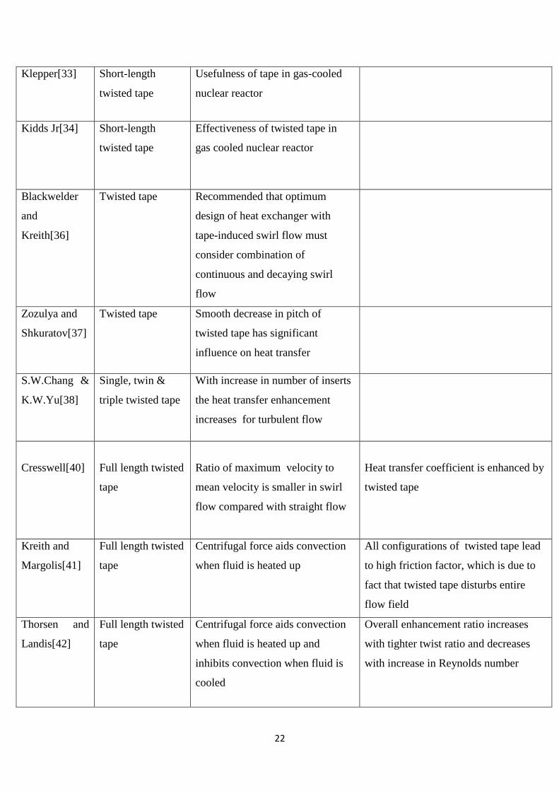
applicable to a wide range of Prandtl number.Klepper [33] and Kidd Jr [34] studied the short-
length twisted tape and compared the results with full length tape. They observed better
performance of the short length twisted tapes over the full length in gas cooled nuclear
reactors. Saha [35] revealed that swirl generated by the tapes breaks down in between the
spacing of regularly spaces twisted tapes. So for a constant heat flux boundary conditions full
length twisted tapes are found to give better performance than the regularly spaced tapes.
Blackwelder and Kreith [36] gave the concept of continuous and decaying swirl flow
generated by the twisted tapes in the turbulent flow. Zozulya and Shkuratov [37] studied the
effect of the pitch of the twisted tapes in the heat transfer process and reported the increase in
the heat transfer coefficient for small reduction in pitch.
Shyy Woei Chang & Ker Wei Yu [38] investigated the effect of increase in number of
inserts. They found that the heat transfer rate increases for turbulent flow (based on same
pumping power consumption) but the same is not true for the laminar flow where negative
effect has been observed. Rao and Sastri [39], studied the rotating tube with a twisted tape
insert, observed that increase in heat transfer rate compensates for the increase in frictional
losses.
21
Author Configuration of
tape
Observations Comments
Zimparov et.
al.[24]
Angled spiralling
tape inserts,
Spiralled tube
Enhancement in the annulus side Angled spiralling tape inserts more
efficient than spiralled tube.
Watcharin
et.al[25]
Twisted tape insert Effect on heat transfer and friction
factor
Nusselt number and friction factor
increases with decrease in twist ratio.
Smith et .al
[26]
Short length
twisted tape
Nusselt number, friction factor,
enhancement efficiency
characteristics.
Promvonge
[27]
Twisted tape and
wire coil
turbulators
Double increase in heat transfer
than wire coil and tape alone
Smith et. al.
[28]
Single twisted
tapes, full length
dual and regularly
spaced dual
twisted tapes.
Full length dual twisted tapes yield
higher heat transfer enhancement
than regularly spaced twisted
tapes.
C.Thianpong
et.al.[29]
Dimple tube fitted
with twisted tape
Both heat transfer and friction
factor are higher than dimpled tube
and plain tube alone.
Heat transfer coefficient and friction
factor increases as pitch ratio and twist
ratio decreases.
Al-Fahed and
Chakroun [30]
Loose fit tapes and
tight –fit tape
For same twist ratio effect of loose
fit and tight fit twisted tape are
same.
S.Eiamsa-ard ,
P. Promvonge
[31]
Full length helical
tape with or
without centred
rod and regularly
spaced helical tape
Full length helical tape with rod
provide highest heat transfer rate
Table 2.4 SUMMARIES OF IMPORTANT INVESTIGATIONS OF TWISTED TAPE IN TURBULENT FLOW [6]
22
Klepper[33] Short-length
twisted tape
Usefulness of tape in gas-cooled
nuclear reactor
Kidds Jr[34] Short-length
twisted tape
Effectiveness of twisted tape in
gas cooled nuclear reactor
Blackwelder
and
Kreith[36]
Twisted tape Recommended that optimum
design of heat exchanger with
tape-induced swirl flow must
consider combination of
continuous and decaying swirl
flow
Zozulya and
Shkuratov[37]
Twisted tape Smooth decrease in pitch of
twisted tape has significant
influence on heat transfer
S.W.Chang &
K.W.Yu[38]
Single, twin &
triple twisted tape
With increase in number of inserts
the heat transfer enhancement
increases for turbulent flow
Cresswell[40]
Full length twisted
tape
Ratio of maximum velocity to
mean velocity is smaller in swirl
flow compared with straight flow
Heat transfer coefficient is enhanced by
twisted tape
Kreith and
Margolis[41]
Full length twisted
tape
Centrifugal force aids convection
when fluid is heated up
All configurations of twisted tape lead
to high friction factor, which is due to
fact that twisted tape disturbs entire
flow field
Thorsen and
Landis[42]
Full length twisted
tape
Centrifugal force aids convection
when fluid is heated up and
inhibits convection when fluid is
cooled
Overall enhancement ratio increases
with tighter twist ratio and decreases
with increase in Reynolds number

23
Colburn and
King[43]
Inserts like baffled
tube and
short-length
twisted tape
Short-length twisted tapes more
effective than full-length twisted
tapes
Seymour[44] Short-length
twisted tape
Short-length twisted tapes more
effective than full-length twisted
tapes
Kreith and
Sonju[45]
Short-length
twisted tape
Short-length (25–45 per cent of
tube length) tapes perform better
than full-length tapes
Huang and
Tsou[46]
Twisted tape Studied free swirl flow

24
CHAPTER 3
PRESENT EXPERIMENTAL WORK
25
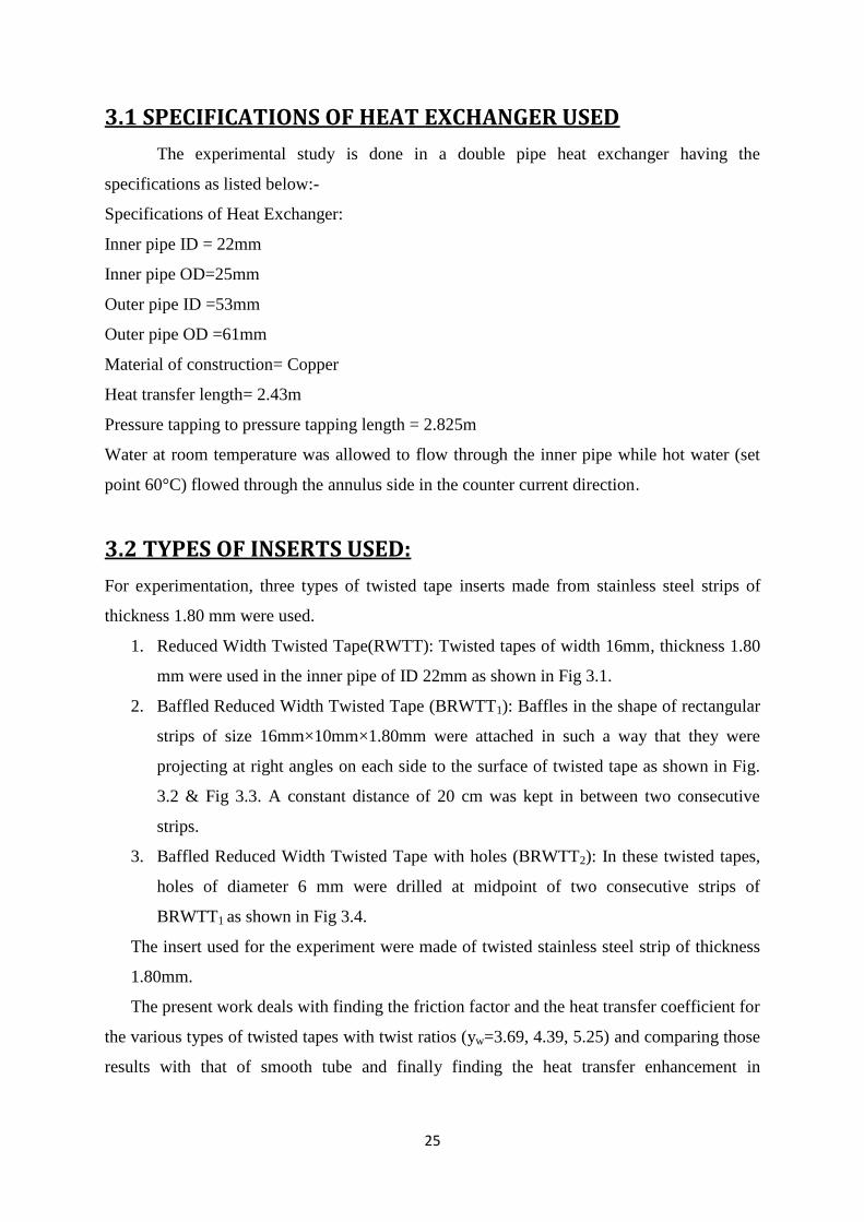
3.1 SPECIFICATIONS OF HEAT EXCHANGER USED
The experimental study is done in a double pipe heat exchanger having the
specifications as listed below:-
Specifications of Heat Exchanger:
Inner pipe ID = 22mm
Inner pipe OD=25mm
Outer pipe ID =53mm
Outer pipe OD =61mm
Material of construction= Copper
Heat transfer length= 2.43m
Pressure tapping to pressure tapping length = 2.825m
Water at room temperature was allowed to flow through the inner pipe while hot water (set
point 60°C) flowed through the annulus side in the counter current direction.
3.2 TYPES OF INSERTS USED:
For experimentation, three types of twisted tape inserts made from stainless steel strips of
thickness 1.80 mm were used.
1. Reduced Width Twisted Tape(RWTT): Twisted tapes of width 16mm, thickness 1.80
mm were used in the inner pipe of ID 22mm as shown in Fig 3.1.
2. Baffled Reduced Width Twisted Tape (BRWTT1): Baffles in the shape of rectangular
strips of size 16mm×10mm×1.80mm were attached in such a way that they were
projecting at right angles on each side to the surface of twisted tape as shown in Fig.
3.2 & Fig 3.3. A constant distance of 20 cm was kept in between two consecutive
strips.
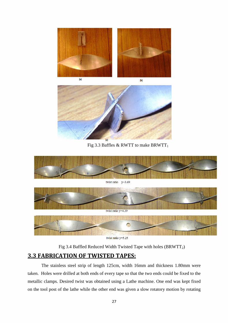
3. Baffled Reduced Width Twisted Tape with holes (BRWTT2): In these twisted tapes,
holes of diameter 6 mm were drilled at midpoint of two consecutive strips of
BRWTT1 as shown in Fig 3.4.
The insert used for the experiment were made of twisted stainless steel strip of thickness
1.80mm.
The present work deals with finding the friction factor and the heat transfer coefficient for
the various types of twisted tapes with twist ratios (yw=3.69, 4.39, 5.25) and comparing those
results with that of smooth tube and finally finding the heat transfer enhancement in
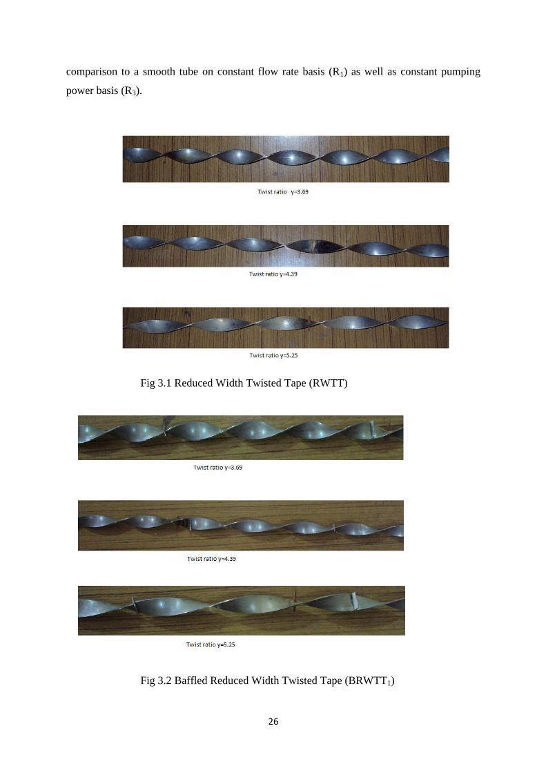
26
comparison to a smooth tube on constant flow rate basis (R1) as well as constant pumping
power basis (R3).
Fig 3.1 Reduced Width Twisted Tape (RWTT)
Fig 3.2 Baffled Reduced Width Twisted Tape (BRWTT1)
27
Fig 3.3 Baffles & RWTT to make BRWTT1
Fig 3.4 Baffled Reduced Width Twisted Tape with holes (BRWTT2)
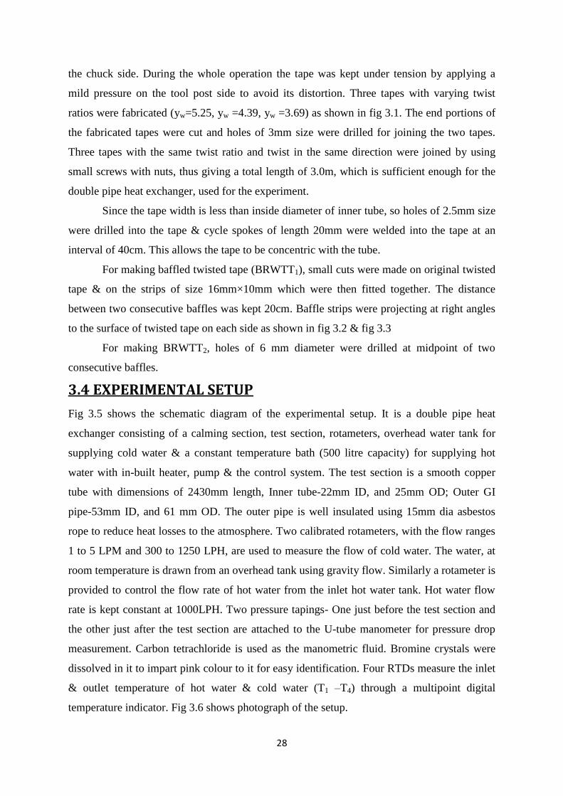
3.3 FABRICATION OF TWISTED TAPES:
The stainless steel strip of length 125cm, width 16mm and thickness 1.80mm were
taken. Holes were drilled at both ends of every tape so that the two ends could be fixed to the
metallic clamps. Desired twist was obtained using a Lathe machine. One end was kept fixed
on the tool post of the lathe while the other end was given a slow rotatory motion by rotating
28
the chuck side. During the whole operation the tape was kept under tension by applying a
mild pressure on the tool post side to avoid its distortion. Three tapes with varying twist
ratios were fabricated (yw=5.25, yw =4.39, yw =3.69) as shown in fig 3.1. The end portions of
the fabricated tapes were cut and holes of 3mm size were drilled for joining the two tapes.
Three tapes with the same twist ratio and twist in the same direction were joined by using
small screws with nuts, thus giving a total length of 3.0m, which is sufficient enough for the
double pipe heat exchanger, used for the experiment.
Since the tape width is less than inside diameter of inner tube, so holes of 2.5mm size
were drilled into the tape & cycle spokes of length 20mm were welded into the tape at an
interval of 40cm. This allows the tape to be concentric with the tube.
For making baffled twisted tape (BRWTT1), small cuts were made on original twisted
tape & on the strips of size 16mm×10mm which were then fitted together. The distance
between two consecutive baffles was kept 20cm. Baffle strips were projecting at right angles
to the surface of twisted tape on each side as shown in fig 3.2 & fig 3.3
For making BRWTT2, holes of 6 mm diameter were drilled at midpoint of two
consecutive baffles.
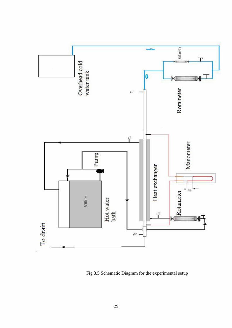
3.4 EXPERIMENTAL SETUP
Fig 3.5 shows the schematic diagram of the experimental setup. It is a double pipe heat
exchanger consisting of a calming section, test section, rotameters, overhead water tank for
supplying cold water & a constant temperature bath (500 litre capacity) for supplying hot
water with in-built heater, pump & the control system. The test section is a smooth copper
tube with dimensions of 2430mm length, Inner tube-22mm ID, and 25mm OD; Outer GI
pipe-53mm ID, and 61 mm OD. The outer pipe is well insulated using 15mm dia asbestos
rope to reduce heat losses to the atmosphere. Two calibrated rotameters, with the flow ranges
1 to 5 LPM and 300 to 1250 LPH, are used to measure the flow of cold water. The water, at
room temperature is drawn from an overhead tank using gravity flow. Similarly a rotameter is
provided to control the flow rate of hot water from the inlet hot water tank. Hot water flow
rate is kept constant at 1000LPH. Two pressure tapings- One just before the test section and
the other just after the test section are attached to the U-tube manometer for pressure drop
measurement. Carbon tetrachloride is used as the manometric fluid. Bromine crystals were
dissolved in it to impart pink colour to it for easy identification. Four RTDs measure the inlet
& outlet temperature of hot water & cold water (T1 –T4) through a multipoint digital
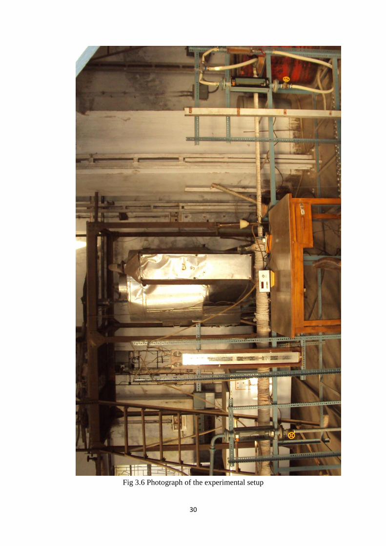
temperature indicator. Fig 3.6 shows photograph of the setup.
29
Fig 3.5 Schematic Diagram for the experimental setup
30
Fig 3.6 Photograph of the experimental setup
31
3.5 EXPERIMENTAL PROCEDURE:
1. All the rotameters & RTD are calibrated first.
i. For rotameter calibration, water is collected in a bucket. Weight of water
collected & time of collection is noted to calculate mass flow rate of water.
ii. A minimum of 3 readings are taken for each flow rate & average flow rate is
used for calculations. The readings are given in A.1.1 & A.1.2
iii. For RTD calibration, all the RTDs are dipped in a constant water bath &
readings shown by each RTD are noted. Temperature shown by one of the
RTD (T1) was taken as reference & corrections were made to other RTDs
values (i.e. T2-T4) accordingly.
2. Twist Ratio(y) of the twisted tapes were calculated.
Twist Ratio, yw = H/W
Where H = Linear distance of the tape for 180° rotation
W = Width of twisted tape
3. Standardization of the set-up:
Before starting the experimental study on friction & heat transfer in heat
exchanger using inserts, standardization of the experimental setup is done by
obtaining the friction factor & heat transfer results for the smooth tube &
comparing them with the standard equations available.
4. For friction factor determination: Pressure drop is measured for each flow rate with
the help of manometer at room temperature.
a. The U-tube manometer used carbon tetrachloride as the manometric liquid. A
little of bromine crystals were added to it to impart a colour to the CCl4.
b. Air bubbles are removed from the manometer so that the liquid levels in both the
limbs were equal when the flow is stopped.
c. Water at room temperature is allowed to flow through the inner pipe of the heat
exchanger.
d. The manometer reading is noted.
5. For heat transfer coefficient calculation:
a) Then, heater is put on to heat the water to 60°C in a constant temperature water
tank of capacity 500 litres. The tank is provided with a centrifugal pump & a
bypass valve for recirculation of hot water to the tank & to the experimental
setup.
32
b) Hot water at about 60°C is allowed to pass through the annulus side of heat
exchanger at 1000LPH (mh=0.2715 Kg/sec).
c) Cold water is now allowed to pass through the tube side of heat exchanger in
counter current direction at a desired flow rate.
d) The water inlet and outlet temperatures for both hot water & cold water (T1-T4)
are recorded only after temperature of both the fluids attains a constant value.
e) The procedure was repeated for different cold water flow rates ranging from
0.0331-0.3492 Kg/sec.
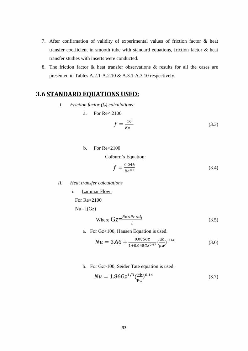
6. Preparation of Wilson chart:
+Rd (3.1)
where Rd is the dirt resistance
All the resistances, except the first term on the RHS of equation (1), are constant for
this set of experiments.
For Re>10000, Seider Tate equation for smooth tube is of the form:
hi=A ×Re0.8
Therefore Eq. (3.1) can be written as
, where K is a constant. (3.2)
K is to be found from the Wilson chart (1/Ui vs. 1/Re0.8
) as the intercept on the y-axis.
K=6.613×10⁻⁴
(Refer Fig 3.7)
Fig 3.7 Wilson chart
y = 0.742x + 6.6132R² = 0.9579
8
8.5
9
9.5
10
10.5
11
11.5
2 2.5 3 3.5 4 4.5 5 5.5 6
10
00
0/U
i
10000/Re^0.8
Wilson Chart
33
7. After confirmation of validity of experimental values of friction factor & heat
transfer coefficient in smooth tube with standard equations, friction factor & heat
transfer studies with inserts were conducted.
8. The friction factor & heat transfer observations & results for all the cases are
presented in Tables A.2.1-A.2.10 & A.3.1-A.3.10 respectively.
3.6 STANDARD EQUATIONS USED:
I. Friction factor (f0) calculations:
a. For Re< 2100
(3.3)
b. For Re>2100
Colburn’s Equation:
(3.4)
II. Heat transfer calculations
i. Laminar Flow:
For Re<2100
Nu= f(Gz)
Where Gz= (3.5)
a. For Gz<100, Hausen Equation is used.
( ) 0.14 (3.6)
b. For Gz>100, Seider Tate equation is used.
(3.7)
34
ii. Transition Zone:
For 2100<Re<10000, Hausen equation is used
(3.8)
iii. Turbulent Zone:
For Re>10000, Seider-Tate equation is used.
(3.9)
Viscosity correction Factor is assumed to be equal to 1 for all
calculations as this value for water in present case will be very close to 1 & the
data for wall temperatures is not measured.
3.7 PRECAUTIONS:
1. While fabricating twisted tapes, exact number of rotations should be measured
for a given twist so that other tapes could be made of exact twist ratio.
2. Rotameters should be calibrated properly to measure exact flow rate of water
for a given rotameter reading.
3. RTDs should be calibrated properly. This is done by measuring temperature the
temperature of water bath by all RTDs at the same time & then taking one of
them as reference.
4. Air bubbles are removed from manometer so that liquid levels in both the limbs
are equal when the flow is stopped. The presence of air bubbles in manometer
can lead to inaccurate readings because of density difference.
5. Temperature readings should be taken only when the inlet & outlet temperature
of both the liquids reach a constant value.

35
CHAPTER 4
SAMPLE CALCULATIONS
36
4.1 ROTAMETER CALIBRATION:
SMALL ROTAMETER
For 4 lpm (Table No. A1.1)
Observation No.1
Weight of water collected=10.2 kg
Time=156 sec
m1=0.06538 kg/sec
Observation No.2
Weight of water collected=10.4 kg
Time=159 sec
m2=0.06541 kg/sec
Observation No.3
Weight of water collected=10.8 kg
Time=165 sec
m3=0.06545 kg/sec
m= =0.06542kg/sec
% difference= = 1.87%
4.2 PRESSURE DROP & FRICTION FACTOR CALULATIONS:
For BRWTT1 having yw=3.69 (Table No.A2.5)
m=0.2090 Kg/sec
Experimental friction factor
Area A= = 3.8 10-4
m2
=0.55m/sec
= (1603-1000) 9.81 0.831=4916 N/m2
= =63.29×10⁻³
37
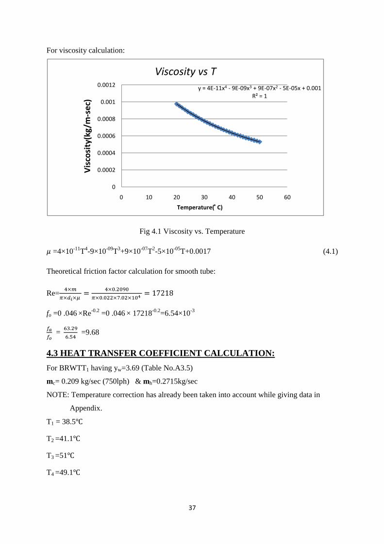
For viscosity calculation:
Fig 4.1 Viscosity vs. Temperature
=4×10-11
T4-9×10
-09T
3+9×10
-07T
2-5×10
-05T+0.0017 (4.1)
Theoretical friction factor calculation for smooth tube:
Re=
fo =0 .046 ×Re-0.2
=0 .046 × 17218-0.2
=6.54×10-3
= =9.68
4.3 HEAT TRANSFER COEFFICIENT CALCULATION:
For BRWTT1 having yw=3.69 (Table No.A3.5)
mc= 0.209 kg/sec (750lph) & mh=0.2715kg/sec
NOTE: Temperature correction has already been taken into account while giving data in
Appendix.
T1 = 38.5
T2 =41.1
T3 =51
T4 =49.1
y = 4E-11x4 - 9E-09x3 + 9E-07x2 - 5E-05x + 0.001R² = 1
0
0.0002
0.0004
0.0006
0.0008
0.001
0.0012
0 10 20 30 40 50 60
Vis
cosi
ty(k
g/m
-se
c)
Temperature( ͦ C)
Viscosity vs T
38
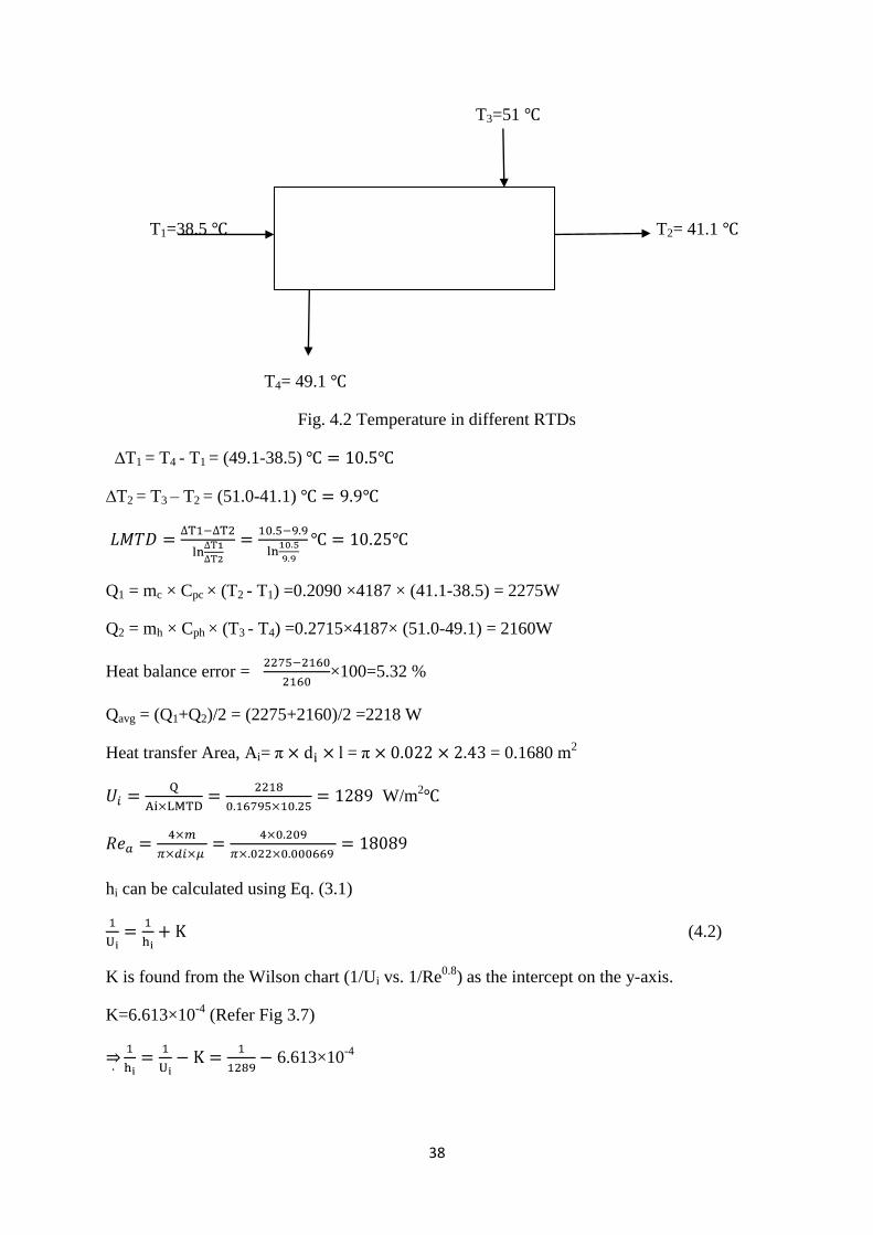
T3=51
T1=38.5 T2= 41.1
T4= 49.1
Fig. 4.2 Temperature in different RTDs
∆T1 = T4 - T1 = (49.1-38.5)
∆T2 = T3 – T2 = (51.0-41.1)
Q1 = mc × Cpc × (T2 - T1) =0.2090 ×4187 × (41.1-38.5) = 2275W
Q2 = mh × Cph × (T3 - T4) =0.2715×4187× (51.0-49.1) = 2160W
Heat balance error = ×100=5.32 %
Qavg = (Q1+Q2)/2 = (2275+2160)/2 =2218 W
Heat transfer Area, Ai= = = 0.1680 m2
W/m2
hi can be calculated using Eq. (3.1)
(4.2)
K is found from the Wilson chart (1/Ui vs. 1/Re0.8
) as the intercept on the y-axis.
K=6.613×10⁻⁴
(Refer Fig 3.7)
6.613×10⁻⁴
39
8721 W/m2 °
C
Theoretical Calculation for smooth tube
(4.3)
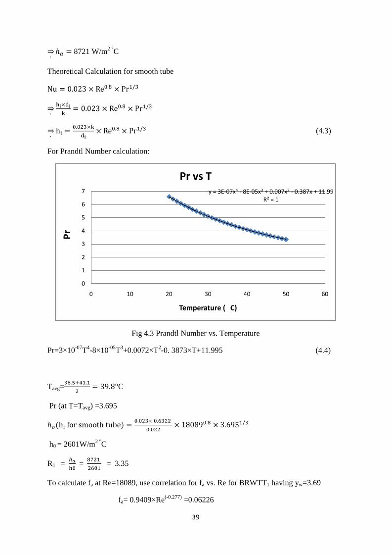
For Prandtl Number calculation:
Fig 4.3 Prandtl Number vs. Temperature
Pr=3×10-07
T4-8×10
-05T
3+0.0072×T
2-0. 3873×T+11.995 (4.4)
Tavg= °C
Pr (at T=Tavg) =3.695
h0 = 2601W/m2 °
C
R1 = = = 3.35
To calculate fa at Re=18089, use correlation for fa vs. Re for BRWTT1 having yw=3.69
fa= 0.9409×Re(-0.277)
=0.06226
y = 3E-07x4 - 8E-05x3 + 0.007x2 - 0.387x + 11.99R² = 1
0
1
2
3
4
5
6
7
0 10 20 30 40 50 60
Pr
Temperature ( C)
Pr vs T
40
For equal pumping power,
(f×Re3×Ax)a= (f×Re
3×Ax)o (4.5)
Axo= ×di2= ×0.022
2 =3.80×10
-4
Axa ×di2-t×w = ×0.022
2 -0.002×0.016=3.48×10
-4
fo×Reo3=( fa×Rea
3×Axa/Axo)
Reo = 39341
ho at Reo(Equivalent Reynolds number in the smooth tube for same pumping power)
ho= =4843 W/m2°
C
R3= = =1.80

41
CHAPTER 5
RESULTS & DISCUSSION
42
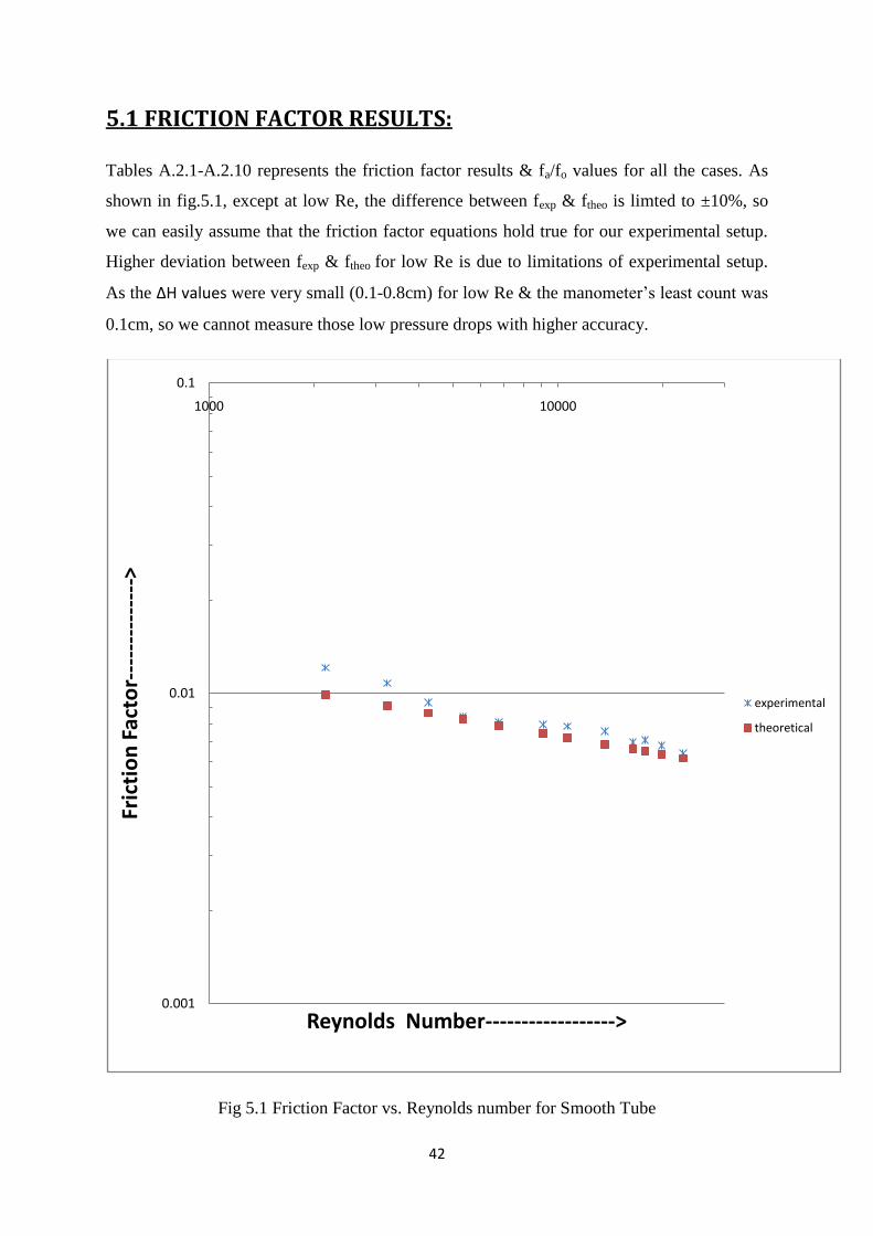
5.1 FRICTION FACTOR RESULTS:
Tables A.2.1-A.2.10 represents the friction factor results & fa/fo values for all the cases. As
shown in fig.5.1, except at low Re, the difference between fexp & ftheo is limted to ±10%, so
we can easily assume that the friction factor equations hold true for our experimental setup.
Higher deviation between fexp & ftheo for low Re is due to limitations of experimental setup.
As the ∆H values were very small (0.1-0.8cm) for low Re & the manometer’s least count was
0.1cm, so we cannot measure those low pressure drops with higher accuracy.
Fig 5.1 Friction Factor vs. Reynolds number for Smooth Tube
0.001
0.01
0.1
1000 10000
Fric
tio
n F
acto
r---
----
----
--->
Reynolds Number------------------>
experimental
theoretical
43
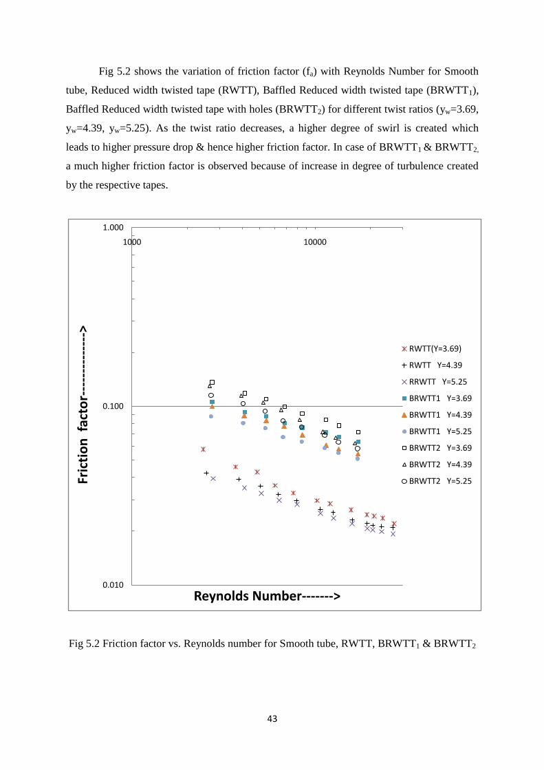
Fig 5.2 shows the variation of friction factor (fa) with Reynolds Number for Smooth
tube, Reduced width twisted tape (RWTT), Baffled Reduced width twisted tape (BRWTT1),
Baffled Reduced width twisted tape with holes (BRWTT2) for different twist ratios (yw=3.69,
yw=4.39, yw=5.25). As the twist ratio decreases, a higher degree of swirl is created which
leads to higher pressure drop & hence higher friction factor. In case of BRWTT1 & BRWTT2,
a much higher friction factor is observed because of increase in degree of turbulence created
by the respective tapes.
Fig 5.2 Friction factor vs. Reynolds number for Smooth tube, RWTT, BRWTT1 & BRWTT2
0.010
0.100
1.000
1000 10000
Fric
tio
n f
acto
r---
----
----
--->
Reynolds Number------->
RWTT(Y=3.69)
RWTT Y=4.39
RRWTT Y=5.25
BRWTT1 Y=3.69
BRWTT1 Y=4.39
BRWTT1 Y=5.25
BRWTT2 Y=3.69
BRWTT2 Y=4.39
BRWTT2 Y=5.25
44
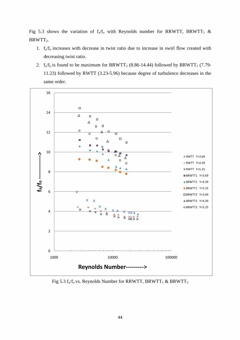
Fig 5.3 shows the variation of fa/fo with Reynolds number for RRWTT, BRWTT1 &
BRWTT2.
1. fa/fo increases with decrease in twist ratio due to increase in swirl flow created with
decreasing twist ratio.
2. fa/fo is found to be maximum for BRWTT2 (8.86-14.44) followed by BRWTT1 (7.79-
11.23) followed by RWTT (3.23-5.96) because degree of turbulence decreases in the
same order.
Fig 5.3 fa/fo vs. Reynolds Number for RRWTT, BRWTT1 & BRWTT2
0
2
4
6
8
10
12
14
16
1000 10000 100000
fa/f
o--
----
----
-->
Reynolds Number--------->
RWTT Y=3.69
RWTT Y=4.39
RWTT Y=5.25
BRWTT1 Y=3.69
BRWTT1 Y=4.39
BRWTT1 Y=5.25
BRWTT2 Y=3.69
BRWTT2 Y=4.39
BRWTT2 Y=5.25
45
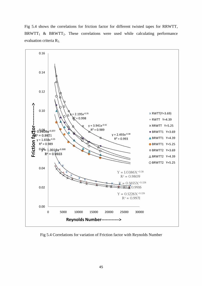
Fig 5.4 shows the correlations for friction factor for different twisted tapes for RRWTT,
BRWTT1 & BRWTT2. These correlations were used while calculating performance
evaluation criteria R3.
Fig 5.4 Correlations for variation of Friction factor with Reynolds Number
y = 1.0386x-0.38
R² = 0.9809
y = 0.5655x-0.328
R² = 0.9916
y = 0.5226x-0.326
R² = 0.9971
y = 0.9409x-0.277
R² = 0.9971
y = 1.658x-0.35
R² = 0.989
y = 1.0016x-0.305
R² = 0.9923
y = 2.195x-0.35
R² = 0.998
y = 3.941x-0.42
R² = 0.989
y = 2.493x-0.38
R² = 0.993
0.00
0.02
0.04
0.06
0.08
0.10
0.12
0.14
0.16
0 5000 10000 15000 20000 25000 30000
Fric
tio
n f
acto
r---
----
----
->
Reynolds Number------------>
RWTT(Y=3.69)
RWTT Y=4.39
RRWTT Y=5.25
BRWTT1 Y=3.69
BRWTT1 Y=4.39
BRWTT1 Y=5.25
BRWTT2 Y=3.69
BRWTT2 Y=4.39
BRWTT2 Y=5.25
46
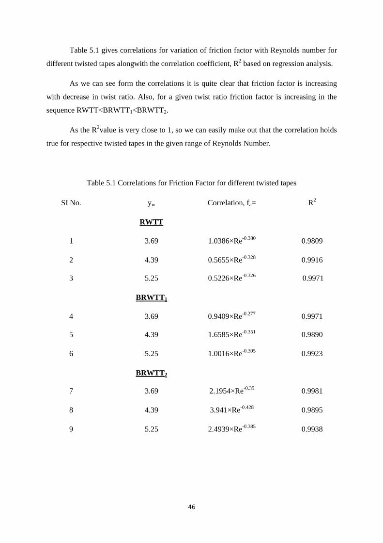
Table 5.1 gives correlations for variation of friction factor with Reynolds number for
different twisted tapes alongwith the correlation coefficient, R2 based on regression analysis.
As we can see form the correlations it is quite clear that friction factor is increasing
with decrease in twist ratio. Also, for a given twist ratio friction factor is increasing in the
sequence RWTT<BRWTT1<BRWTT2.
As the R2value is very close to 1, so we can easily make out that the correlation holds
true for respective twisted tapes in the given range of Reynolds Number.
Table 5.1 Correlations for Friction Factor for different twisted tapes
SI No. yw Correlation, fa= R2
RWTT
1 3.69 1.0386×Re-0.380
0.9809
2 4.39 0.5655×Re-0.328
0.9916
3 5.25 0.5226×Re-0.326
0.9971
BRWTT1
4 3.69 0.9409×Re-0.277
0.9971
5 4.39 1.6585×Re-0.351
0.9890
6 5.25 1.0016×Re-0.305
0.9923
BRWTT2
7 3.69 2.1954×Re-0.35
0.9981
8 4.39 3.941×Re-0.428
0.9895
9 5.25 2.4939×Re-0.385
0.9938
47
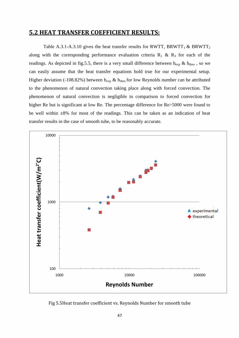
5.2 HEAT TRANSFER COEFFICIENT RESULTS:
Table A.3.1-A.3.10 gives the heat transfer results for RWTT, BRWTT1 & BRWTT2
along with the corresponding performance evaluation criteria R1 & R3 for each of the
readings. As depicted in fig.5.5, there is a very small difference between hexp & htheo , so we
can easily assume that the heat transfer equations hold true for our experimental setup.
Higher deviation (-108.82%) between hexp & htheo for low Reynolds number can be attributed
to the phenomenon of natural convection taking place along with forced convection. The
phenomenon of natural convection is negligible in comparison to forced convection for
higher Re but is significant at low Re. The percentage difference for Re>5000 were found to
be well within ±8% for most of the readings. This can be taken as an indication of heat
transfer results in the case of smooth tube, to be reasonably accurate.
Fig 5.5Heat transfer coefficient vs. Reynolds Number for smooth tube
100
1000
10000
1000 10000 100000
He
at t
ran
sfe
r co
effi
cie
nt(
W/m
2° C
)
Reynolds Number
exp
theo
48
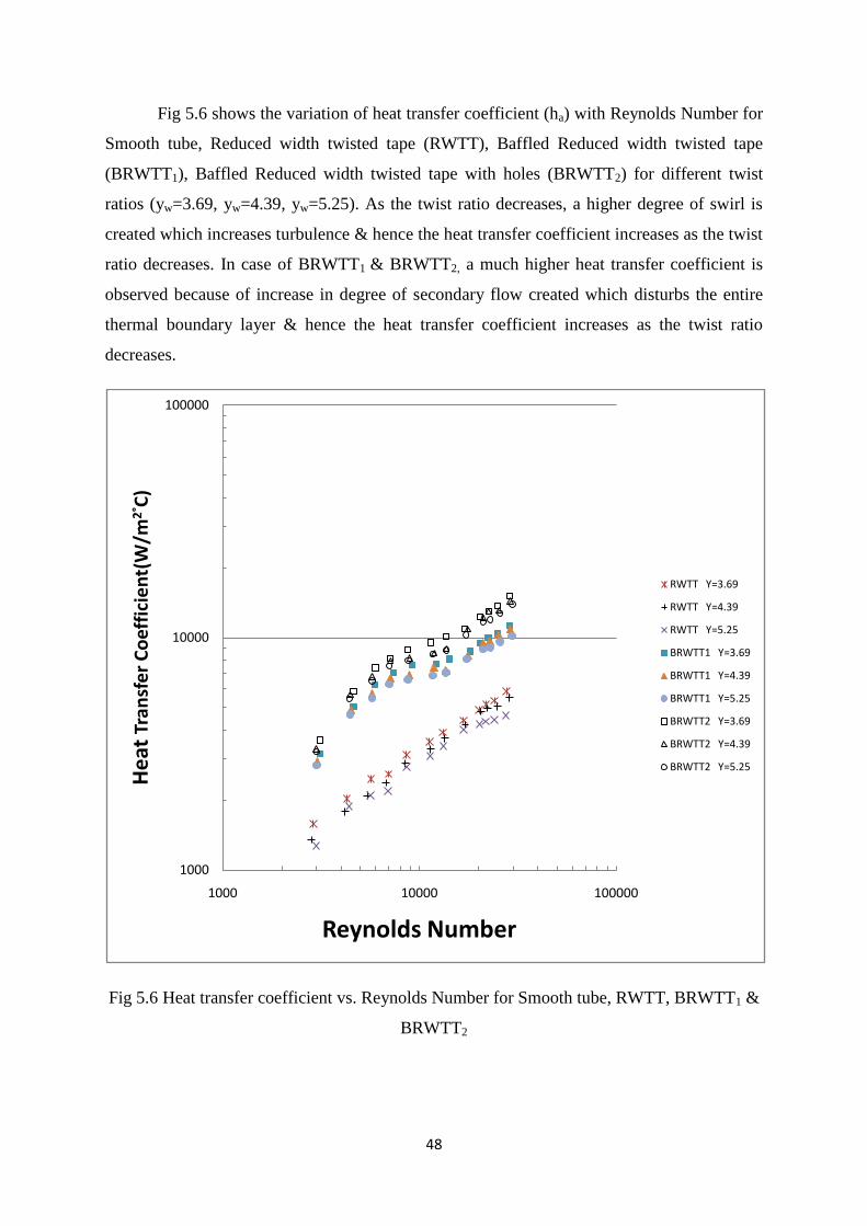
Fig 5.6 shows the variation of heat transfer coefficient (ha) with Reynolds Number for
Smooth tube, Reduced width twisted tape (RWTT), Baffled Reduced width twisted tape
(BRWTT1), Baffled Reduced width twisted tape with holes (BRWTT2) for different twist
ratios (yw=3.69, yw=4.39, yw=5.25). As the twist ratio decreases, a higher degree of swirl is
created which increases turbulence & hence the heat transfer coefficient increases as the twist
ratio decreases. In case of BRWTT1 & BRWTT2, a much higher heat transfer coefficient is
observed because of increase in degree of secondary flow created which disturbs the entire
thermal boundary layer & hence the heat transfer coefficient increases as the twist ratio
decreases.
Fig 5.6 Heat transfer coefficient vs. Reynolds Number for Smooth tube, RWTT, BRWTT1 &
BRWTT2
1000
10000
100000
1000 10000 100000
He
at T
ran
sfe
r C
oef
fici
en
t(W
/m2
° C)
Reynolds Number
RWTT Y=3.69
RWTT Y=4.39
RWTT Y=5.25
BRWTT1 Y=3.69
BRWTT1 Y=4.39
BRWTT1 Y=5.25
BRWTT2 Y=3.69
BRWTT2 Y=4.39
BRWTT2 Y=5.25
49
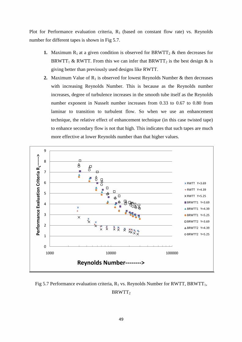
Plot for Performance evaluation criteria, R1 (based on constant flow rate) vs. Reynolds
number for different tapes is shown in Fig 5.7.
1. Maximum R1 at a given condition is observed for BRWTT2 & then decreases for
BRWTT1 & RWTT. From this we can infer that BRWTT2 is the best design & is
giving better than previously used designs like RWTT.
2. Maximum Value of R1 is observed for lowest Reynolds Number & then decreases
with increasing Reynolds Number. This is because as the Reynolds number
increases, degree of turbulence increases in the smooth tube itself as the Reynolds
number exponent in Nusselt number increases from 0.33 to 0.67 to 0.80 from
laminar to transition to turbulent flow. So when we use an enhancement
technique, the relative effect of enhancement technique (in this case twisted tape)
to enhance secondary flow is not that high. This indicates that such tapes are much
more effective at lower Reynolds number than that higher values.
Fig 5.7 Performance evaluation criteria, R1 vs. Reynolds Number for RWTT, BRWTT1,
BRWTT2
0
1
2
3
4
5
6
7
8
9
1000 10000 100000
Per
form
ance
Eva
luat
ion
Cri
teri
a R
1--
----
>
Reynolds Number-------->
RWTT Y=3.69
RWTT Y=4.39
RWTT Y=5.25
BRWTT1 Y=3.69
BRWTT1 Y=4.39
BRWTT1 Y=5.25
BRWTT2 Y=3.69
BRWTT2 Y=4.39
BRWTT2 Y=5.25
50
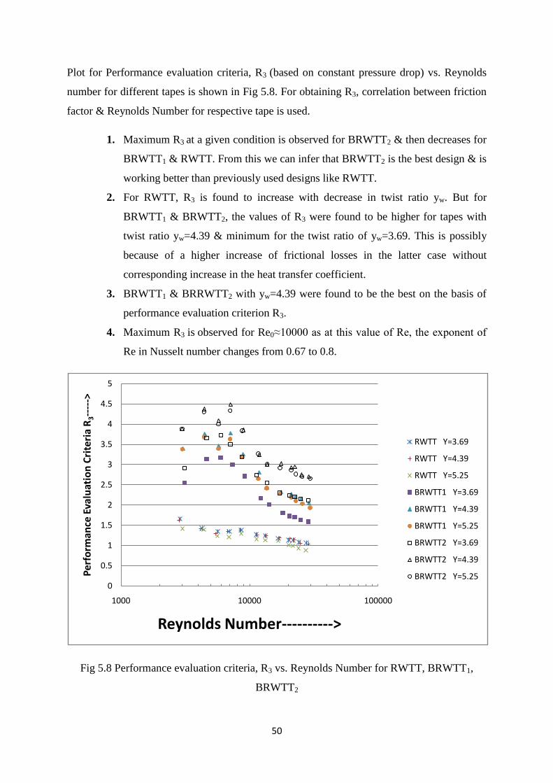
Plot for Performance evaluation criteria, R3 (based on constant pressure drop) vs. Reynolds
number for different tapes is shown in Fig 5.8. For obtaining R3, correlation between friction
factor & Reynolds Number for respective tape is used.
1. Maximum R3 at a given condition is observed for BRWTT2 & then decreases for
BRWTT1 & RWTT. From this we can infer that BRWTT2 is the best design & is
working better than previously used designs like RWTT.
2. For RWTT, R3 is found to increase with decrease in twist ratio yw. But for
BRWTT1 & BRWTT2, the values of R3 were found to be higher for tapes with
twist ratio yw=4.39 & minimum for the twist ratio of yw=3.69. This is possibly
because of a higher increase of frictional losses in the latter case without
corresponding increase in the heat transfer coefficient.
3. BRWTT1 & BRRWTT2 with yw=4.39 were found to be the best on the basis of
performance evaluation criterion R3.
4. Maximum R3 is observed for Re0≈10000 as at this value of Re, the exponent of
Re in Nusselt number changes from 0.67 to 0.8.
Fig 5.8 Performance evaluation criteria, R3 vs. Reynolds Number for RWTT, BRWTT1,
BRWTT2
0
0.5
1
1.5
2
2.5
3
3.5
4
4.5
5
1000 10000 100000
Per
form
ance
Eva
luat
ion
Cri
teri
a R
3--
--->
Reynolds Number---------->
RWTT Y=3.69
RWTT Y=4.39
RWTT Y=5.25
BRWTT1 Y=3.69
BRWTT1 Y=4.39
BRWTT1 Y=5.25
BRWTT2 Y=3.69
BRWTT2 Y=4.39
BRWTT2 Y=5.25
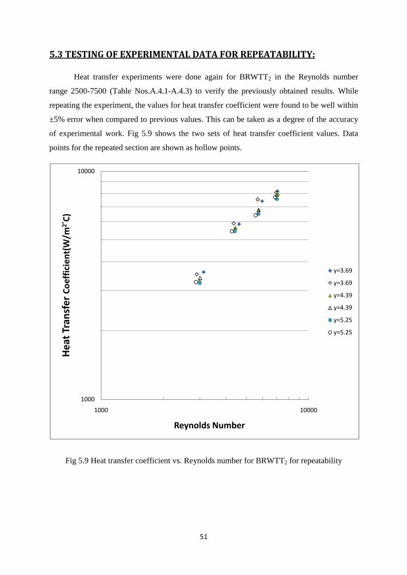
51
5.3 TESTING OF EXPERIMENTAL DATA FOR REPEATABILITY:
Heat transfer experiments were done again for BRWTT2 in the Reynolds number
range 2500-7500 (Table Nos.A.4.1-A.4.3) to verify the previously obtained results. While
repeating the experiment, the values for heat transfer coefficient were found to be well within
±5% error when compared to previous values. This can be taken as a degree of the accuracy
of experimental work. Fig 5.9 shows the two sets of heat transfer coefficient values. Data
points for the repeated section are shown as hollow points.
Fig 5.9 Heat transfer coefficient vs. Reynolds number for BRWTT2 for repeatability
1000
10000
1000 10000
He
at T
ran
sfe
r C
oef
fici
en
t(W
/m2
° C)
Reynolds Number
y=3.69
y=3.69
y=4.39
y=4.39
y=5.25
y=5.25

52
CHAPTER 6
CONCLUSION
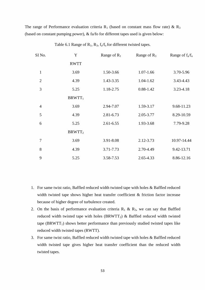
53
The range of Performance evaluation criteria R1 (based on constant mass flow rate) & R3
(based on constant pumping power), & fa/fo for different tapes used is given below:
Table 6.1 Range of R1, R3, fa/fo for different twisted tapes.
SI No. Y Range of R1 Range of R3 Range of fa/fo
RWTT
1 3.69 1.50-3.66 1.07-1.66 3.70-5.96
2 4.39 1.43-3.35 1.04-1.62 3.43-4.43
3 5.25 1.18-2.75 0.88-1.42 3.23-4.18
BRWTT1
4 3.69 2.94-7.07 1.59-3.17 9.68-11.23
5 4.39 2.81-6.73 2.05-3.77 8.29-10.59
6 5.25 2.61-6.55 1.93-3.68 7.79-9.28
BRWTT2
7 3.69 3.91-8.08 2.12-3.73 10.97-14.44
8 4.39 3.71-7.73 2.70-4.49 9.42-13.71
9 5.25 3.58-7.53 2.65-4.33 8.86-12.16
1. For same twist ratio, Baffled reduced width twisted tape with holes & Baffled reduced
width twisted tape shows higher heat transfer coefficient & friction factor increase
because of higher degree of turbulence created.
2. On the basis of performance evaluation criteria R1 & R3, we can say that Baffled
reduced width twisted tape with holes (BRWTT2) & Baffled reduced width twisted
tape (BRWTT1) shows better performance than previously studied twisted tapes like
reduced width twisted tapes (RWTT).
3. For same twist ratio, Baffled reduced width twisted tape with holes & Baffled reduced
width twisted tape gives higher heat transfer coefficient than the reduced width
twisted tapes.
54
4. The correlations derived from friction factor values have R2(Correlation coefficient)
values very close to 1. So, the correlations can be used for finding friction factor
values for respective designs in the given range of Reynolds number.
5. With decrease in twist ratio, heat transfer coefficient increases but at the same time
pressure drop also increases.
6. For RWTT, R3 is found to increase with decrease in twist ratio yw. But for BRWTT1
& BRWTT2, the values of R3 were found to be higher for tapes with twist ratio
yw=4.39 & minimum for the twist ratio of yw=3.69. This is possibly because of a
higher increase of frictional losses in the case of yw=3.69 without a corresponding
increase in heat transfer coefficient.
7. On the basis of performance evaluation criterion R3, twisted tapes-BRWTT1 &
BRRWTT2 with yw=4.39 were found to be the best tape for heat transfer
augmentation.

55
CHAPTER 7
SCOPE FOR FUTURE WORK

56
Further studies can be done using this study as base. Some of the possibilities are mentioned
below:
1. Experimental work can be done at low Reynolds number using viscous liquids, as
the tapes have shown comparatively better results at low Reynolds number.
2. Distance between two consecutive baffles & holes can be varied to see their effect
on heat transfer & friction factor.
3. Geometry of baffles:
a. Circular baffles instead of rectangular baffles can be used.
b. Baffles can be kept at an angle to flow of liquid instead of putting them
perpendicular to flow of liquid.
c. Size of baffles can be varied.
4. The proposed designs can be used for cooling of liquids.
57
REFERENCES:
1. B.Adrian and K. Allan D. Heat transfer enhancement. In Heat Transfer Handbook,
Chapter 14, pg.1033, -1101, Wiley-interscience, 2003.
2. Bergles, A.E. ―Techniques to augment heat transfer.‖ In Handbook of Heat Transfer
Applications (Ed.W.M. Rosenhow), 1985, Ch.3 (McGraw-Hill, New York).
3. Bergles, A.E. and Blumenkrantz, A.R. ―Performance evaluation criteria for enhanced
heat transfer surfaces‖. Proc. Of 5th
Int. Heat Conf., Tokyo, Vol 2, 239-243(1974)
4. Champagne, P.R. and Bergles, A.E. "Development and testing of a novel, variable
roughness technique to enhance, on demand, heat transfer in a single-phase heat
exchanger." Journal of Enhanced Heat Transfer 8, Vol 5 (2001) 341-352.
5. Megerlin et al., 1974. F.E. Megerlin, R.W. Murphy and A.E. Bergles, ―Augmentation
of heat transfer in tubes by use of mesh and brush inserts‖. J. Heat Transfer, 145–
151(1974)
6. A. Dewan, P. Mahanta, K Sumithraju, P. Suresh kumar ―Review of passive heat
transfer augmentation techniques‖. Proc. Institution of Mechanical Engineers Vol. 218
Part A (2004): Journal of Power and Energy.
7. Whitham, J. M. The effects of retarders in fire tubes of steam boilers. Street Railway.
1896, 12(6), 374.
8. Saha, S. K. and Dutta, A. ―Thermo-hydraulic study of laminar swirl flow through a
circular tube fitted with twisted tapes.‖ Trans. ASME, J. Heat Transfer, 2001, 123,
417–421.
9. Date, A. W. and Singham, J. R. Numerical prediction of friction and heat transfer
characteristics of fully developed laminar flow in tubes containing twisted tapes.
Trans. ASME, J. Heat Transfer, 1972, 17, 72.
10. Hong, S. W. and Bergles, A. E. Augmentation of laminar flow heat transfer in tubes by
means of twisted-tape inserts.Trans. ASME J. Heat Transfer, 1976, 98, 251–256.
11. Tariq, A., Kant, K. and Panigrahi, P. K. Heat transfer enhancement using an internally
threaded tube. In Proceedings of 4th ISHMT–ASME Heat and Mass Transfer
Conference, India, 2000, pp. 277–281 (Tata McGraw-Hill, New Delhi).
58
12. Manglik, R. M. and Bergles, A. E. ―Heat transfer and pressure drop correlations for
twisted tape insert in isothermal tubes.‖ Part 1: laminar flows. Trans. ASME, J. Heat
Transfer, 1993, 116, 881–889.
13. Saha, S. K., Dutta, A. and Dhal, S. K. Friction and heat transfer characteristics of
laminar swirl flow through a circular tube fitted with regularly spaced twisted-tape
elements. Int.J. Heat and Mass Transfer, 2001, 44, 4211–4223
14. Lokanath, M. S. and Misal, R. D. An experimental study on the performance of plate
heat exchanger and an augmented shell and tube heat exchanger for different types of
fluids for marine applications. In Proceedings of 5th ISHMT– ASME Heat and Mass
Transfer Conference, India, 2002, pp. 863–868 (Tata McGraw-Hill, New Delhi).
15. Lokanath, M. S. ―Performance evaluation of full length and half length twisted tape
inserts on laminar flow heat transfer in tubes‖. In Proceedings of 3rd ISHMT–ASME
Heat and Mass Transfer Conference, India, 1997, pp. 319–324 (Tata McGraw-Hill,
New Delhi).
16. Al-Fahed, S., Chamra, L. M. and Chakroun, W. Pressure drop and heat transfer
comparison for both micro-fin tube and twisted-tape inserts in laminar flow.
Experimental Thermal and Fluid Sci., 1999, 18, 323–333.
17. Q. Liao, M.D. Xin ―Augmentation of convective heat transfer inside tubes with three-
dimensional internal extended surfaces and twisted-tape inserts’ Chemical Engineering
Journal 78 (2000).
18. Ujhidy et. al, Fluid flow in tubes with helical elements, Chemical Engineering and
Processing 42 (2003), pp. 1–7.
19. Suresh Kumar, P., Mahanta, P. and Dewan, A. Study of laminar flow in a large
diameter annulus with twisted tape inserts. In Proceedings of 2nd International
Conference on Heat Transfer, Fluid Mechanics, and Thermodynamics, Victoria Falls,
Zambia, 2003, paper KP3.
20. Saha, S. K. and Chakraborty, D. ―Heat transfer and pressure drop characteristics of
laminar flow through a circular tube fitted with regularly spaced twisted tape elements
with multiple twists‖. In Proceedings of 3rd ISHMT–ASME Heat and Mass Transfer
Conference, India, 1997, pp. 313–318 (Tata McGraw-Hill, New Delhi).
21. Sivashanmugam, P. and Suresh, S. ―Experimental studies on heat transfer and friction
factor characteristics of turbulent flow through a circular tube fitted with regularly
spaced helical screw tape inserts‖, Experimental Thermal and Fluid Science 31
(2007).301-308.

59
22. Saha, S. K. and Bhunia, K. ―Heat transfer and pressure drop characteristics of varying
pitch twisted-tape-generated laminar smooth swirl flow.‖ 4th ISHMT–ASME Heat and
Mass Transfer Conference, India, 2000, pp. 423–428 (Tata McGraw-Hill, New Delhi).
23. Agarwal, S. K. and Raja Rao, M. Heat transfer augmentation for flow of viscous liquid
in circular tubes using twisted tape inserts. Int. J. Heat Mass Transfer, 1996, 99, 3547–
3557.
24. V. D.Zimparov, P. J.Penchev, and J. P. Meyer. ―Performance evaluation of tube-in-
tube heat exchangers with heat transfer enhancement in the annulus‖. Thermal Science,
vol. 10. (2006), No.1, pp.45-56.
25. Watcharin Noothong, Smith Eiamsa-ard and Pongjet Promvonge ―Effect of Twisted-
tape Inserts on Heat Transfer in a Tube‖. The 2nd Joint International Conference on
―Sustainable Energy and Environment (SEE 2006)‖, 21-23 November 2006, Bangkok,
Thailand
26. Smith Eiamsa-ard, Chinaruk Thianpong, Petpices Eiamsa-ard, Pongjet Promvonge.
―Convective heat transfer in a circular tube with short-length twisted tape insert‖.
Int. communications in heat and mass transfer (2009).
27. Pongjet Promvonge‖ Thermal augmentation in circular tube with twisted tape and
wire coil turbulators‖ Energy Conversion and Management 49 (2008)
2949-2955,Elsevier.
28. Smith Eiamsa-ard, Chinaruk Thianpong, Petpices Eiamsa-ard, Pongjet Promvonge
―Thermal characteristics in a heat exchanger tube fitted with dual twisted tape
elements in tandem‖.Int. communications in heat and mass transfer (2009).
29. Chinaruk Thianpong, Petpices Eiamsa-ard, Khwanchit Wongcharee, Smith Eiamsa-
ard ―Compound heat transfer enhancement of a dimpled tube with a twisted tape swirl
generator‖. International Communications in Heat and Mass Heat and Mass Transfer
36 (2009)698-704.
30. Al-Fahed and Chakroun. Effect of tube- tape clearance on heat transfer for fully
developed turbulent flow in a horizontal isothermal tube‖.Int. J Heat and fluid flow:
17, 173-178, 1996.
31. Smith Eiamsa-ard, Pongjet Promvonge. Enhancement of heat transfers in a tube with
regularly-spaced helical tape swirl generator. Solar Energy 78 (2005) 483–494
60
32. T.S.Ravigururajan and A.E.Bergles. Development and verification of general
correlations for Pressure Drop and Heat transfer in single–phase turbulent flow in
enhanced tubes. Experimental Thermal and Fluid Science, 1996.
33. Klepper, O. H. Heat transfer performance of short twisted tapes. AIChE J., 1972, 35,
1–24.
34. Kidd Jr, Heat transfer and pressure drop for nitrogen flowing in tubes containing
twisted tapes. AIChE J., 1969, 15, 581–585.
35. Saha, S. K., Gaitonde, U. N. and Date, A. W. Heat transfer and pressure drop
characteristics of turbulent flow in circular tube fitted with regularly spaced twisted
tape elements. Expl. Thermal and Fluid Sci., 1990, 3, 632–640.
36. Blackwelder, R. and Kreith, F. Experimental investigation of heat transfer and pressure
drop in a decaying swirl flow. Trans. ASME Augmentation of Convective Heat and
Mass Transfer, 1970, 102–108
37. Zozulya, N. V. and Shkuratov, I. Y. Effect of length of twisted tape turbulence
promoter and its initial twisting pitch on augmentation of heat transfer inside a tube.
Heat Transfer Sov. Res., 1974, 6, 98–100.
38. Shyy Woei Chang, Ker Wui Yu ―Heat Transfers in tubes fitted with single, twin, triple
Twisted tapes‖, Experimental Heat Transfer.vol 18, 2005, pgs.279-294.
39. Rao, M. M. and Sastri, V. M. K. Experimental investigation for fluid flow and heat
transfer in a rotating tube twisted tape inserts. Int. J. Heat and Mass Transfer, 1995, 16,
19–28.
40. Cresswell, J. D. Mechanism of swirling turbulent flow. MS thesis, Lehigh University,
USA, 1958.
41. Kreith, F. and Margolis, D. Heat transfer and friction in turbulent vortex flow. Appl.
Sci. Res., 1959, 8, 457–473.
42. Thorsen, R. and Landis, F. Friction and heat transfer characteristics in tubular swirl
flow subjected to large transverse temperature gradients. Trans. ASME, J. Heat
Transfer, 1968, 90, 87–97.
43. Colburn, A. P. and King, W. J. Heat transfer and pressure drop in empty, baffled and
packed tubes. III: relation between heat transfer and pressure drop. Industrial Engg
Chem., 1931, 23, 919–923.
44. Seymour, E. V. A note on the improvement in performance obtainable from fitting
twisted-tape turbulence promoters to tubular heat exchangers. J. IChE, 1963, 41, 159–
162.

61
45. Kreith, F. and Sonju, O. K. The decay of a turbulent swirl flow in a pipe. J. Fluid
Mechanics, 1965, 22, 257–271.
46. Huang, F. and Tsou, F. K. Friction and heat transfer in turbulence free swirl flow in
pipes. Trans. ASME, J. Heat Transfer, 1979, 39, 1–9.

62
Appendix
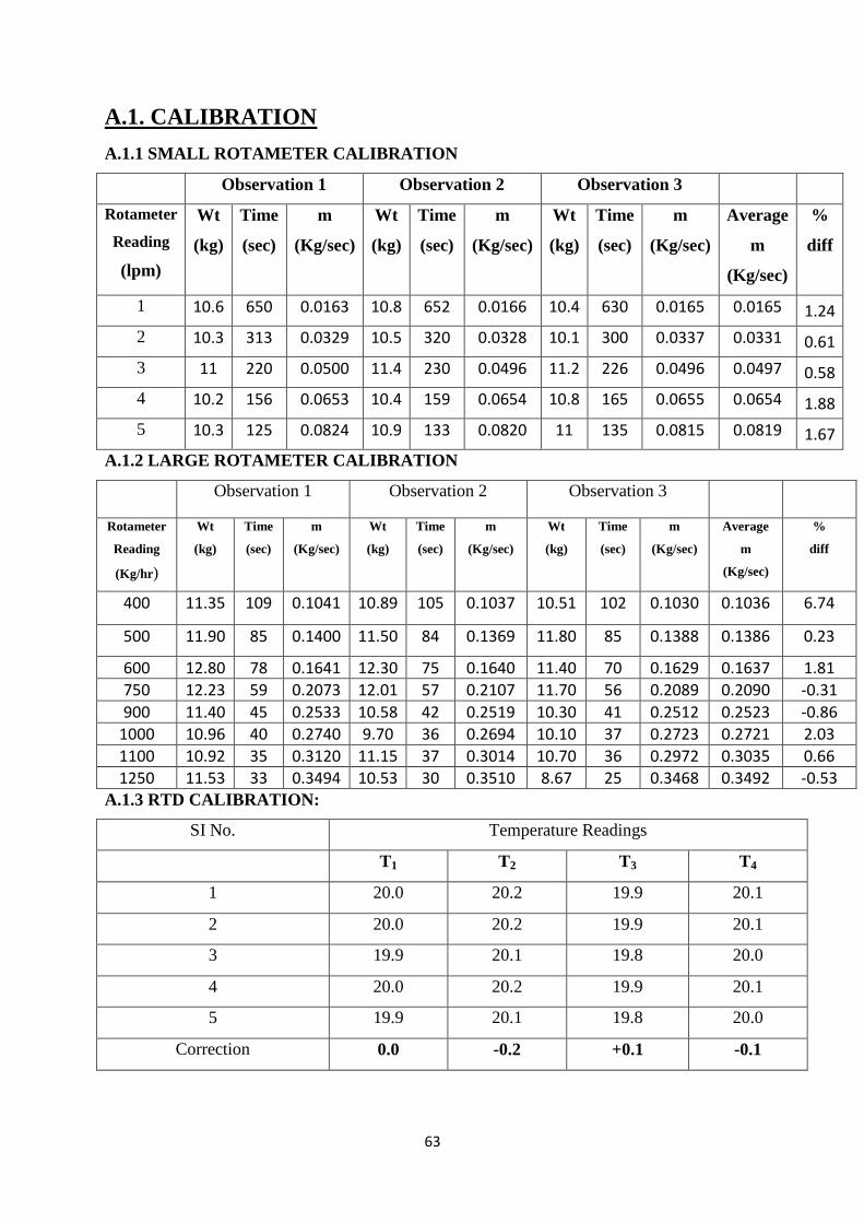
63
A.1. CALIBRATION
A.1.1 SMALL ROTAMETER CALIBRATION
Observation 1 Observation 2 Observation 3
Rotameter
Reading
(lpm)
Wt
(kg)
Time
(sec)
m
(Kg/sec)
Wt
(kg)
Time
(sec)
m
(Kg/sec)
Wt
(kg)
Time
(sec)
m
(Kg/sec)
Average
m
(Kg/sec)
%
diff
1 10.6 650 0.0163 10.8 652 0.0166 10.4 630 0.0165 0.0165 1.24
2 10.3 313 0.0329 10.5 320 0.0328 10.1 300 0.0337 0.0331 0.61
3 11 220 0.0500 11.4 230 0.0496 11.2 226 0.0496 0.0497 0.58
4 10.2 156 0.0653 10.4 159 0.0654 10.8 165 0.0655 0.0654 1.88
5 10.3 125 0.0824 10.9 133 0.0820 11 135 0.0815 0.0819 1.67
A.1.2 LARGE ROTAMETER CALIBRATION
Observation 1 Observation 2 Observation 3
Rotameter
Reading
(Kg/hr)
Wt
(kg)
Time
(sec)
m
(Kg/sec)
Wt
(kg)
Time
(sec)
m
(Kg/sec)
Wt
(kg)
Time
(sec)
m
(Kg/sec)
Average
m
(Kg/sec)
%
diff
400 11.35 109 0.1041 10.89 105 0.1037 10.51 102 0.1030 0.1036 6.74
500 11.90 85 0.1400 11.50 84 0.1369 11.80 85 0.1388 0.1386 0.23
600 12.80 78 0.1641 12.30 75 0.1640 11.40 70 0.1629 0.1637 1.81
750 12.23 59 0.2073 12.01 57 0.2107 11.70 56 0.2089 0.2090 -0.31
900 11.40 45 0.2533 10.58 42 0.2519 10.30 41 0.2512 0.2523 -0.86
1000 10.96 40 0.2740 9.70 36 0.2694 10.10 37 0.2723 0.2721 2.03
1100 10.92 35 0.3120 11.15 37 0.3014 10.70 36 0.2972 0.3035 0.66
1250 11.53 33 0.3494 10.53 30 0.3510 8.67 25 0.3468 0.3492 -0.53 A.1.3 RTD CALIBRATION:
SI No. Temperature Readings
T1 T2 T3 T4
1 20.0 20.2 19.9 20.1
2 20.0 20.2 19.9 20.1
3 19.9 20.1 19.8 20.0
4 20.0 20.2 19.9 20.1
5 19.9 20.1 19.8 20.0
Correction 0.0 -0.2 +0.1 -0.1
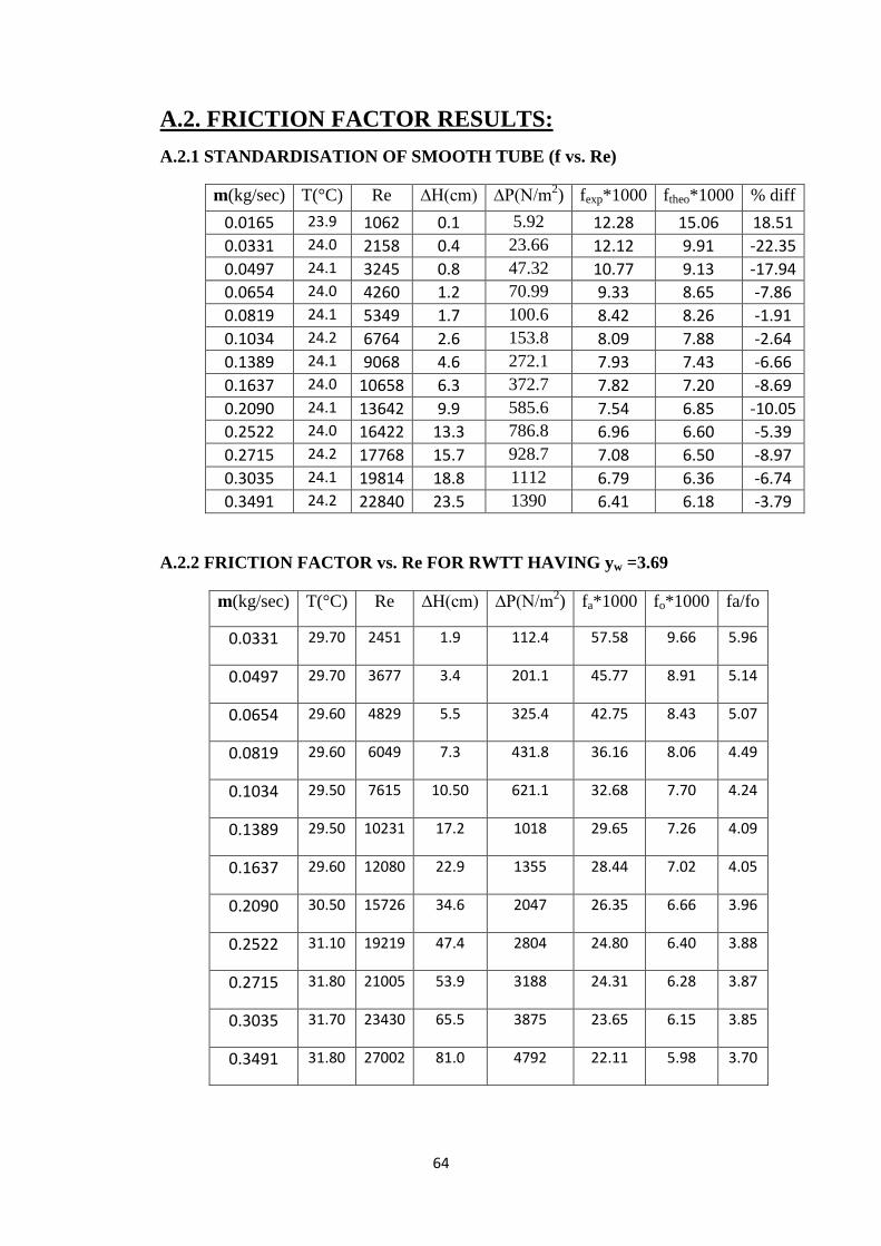
64
A.2. FRICTION FACTOR RESULTS:
A.2.1 STANDARDISATION OF SMOOTH TUBE (f vs. Re)
m(kg/sec) T(°C) Re ∆H(cm) ∆P(N/m2) fexp*1000 ftheo*1000 % diff
0.0165 23.9 1062 0.1 5.92 12.28 15.06 18.51
0.0331 24.0 2158 0.4 23.66 12.12 9.91 -22.35
0.0497 24.1 3245 0.8 47.32 10.77 9.13 -17.94
0.0654 24.0 4260 1.2 70.99 9.33 8.65 -7.86
0.0819 24.1 5349 1.7 100.6 8.42 8.26 -1.91
0.1034 24.2 6764 2.6 153.8 8.09 7.88 -2.64
0.1389 24.1 9068 4.6 272.1 7.93 7.43 -6.66
0.1637 24.0 10658 6.3 372.7 7.82 7.20 -8.69
0.2090 24.1 13642 9.9 585.6 7.54 6.85 -10.05
0.2522 24.0 16422 13.3 786.8 6.96 6.60 -5.39
0.2715 24.2 17768 15.7 928.7 7.08 6.50 -8.97
0.3035 24.1 19814 18.8 1112 6.79 6.36 -6.74
0.3491 24.2 22840 23.5 1390 6.41 6.18 -3.79
A.2.2 FRICTION FACTOR vs. Re FOR RWTT HAVING yw =3.69
m(kg/sec) T(°C) Re ∆H(cm) ∆P(N/m2) fa*1000 fo*1000 fa/fo
0.0331 29.70 2451 1.9 112.4 57.58 9.66 5.96
0.0497 29.70 3677 3.4 201.1 45.77 8.91 5.14
0.0654 29.60 4829 5.5 325.4 42.75 8.43 5.07
0.0819 29.60 6049 7.3 431.8 36.16 8.06 4.49
0.1034 29.50 7615 10.50 621.1 32.68 7.70 4.24
0.1389 29.50 10231 17.2 1018 29.65 7.26 4.09
0.1637 29.60 12080 22.9 1355 28.44 7.02 4.05
0.2090 30.50 15726 34.6 2047 26.35 6.66 3.96
0.2522 31.10 19219 47.4 2804 24.80 6.40 3.88
0.2715 31.80 21005 53.9 3188 24.31 6.28 3.87
0.3035 31.70 23430 65.5 3875 23.65 6.15 3.85
0.3491 31.80 27002 81.0 4792 22.11 5.98 3.70
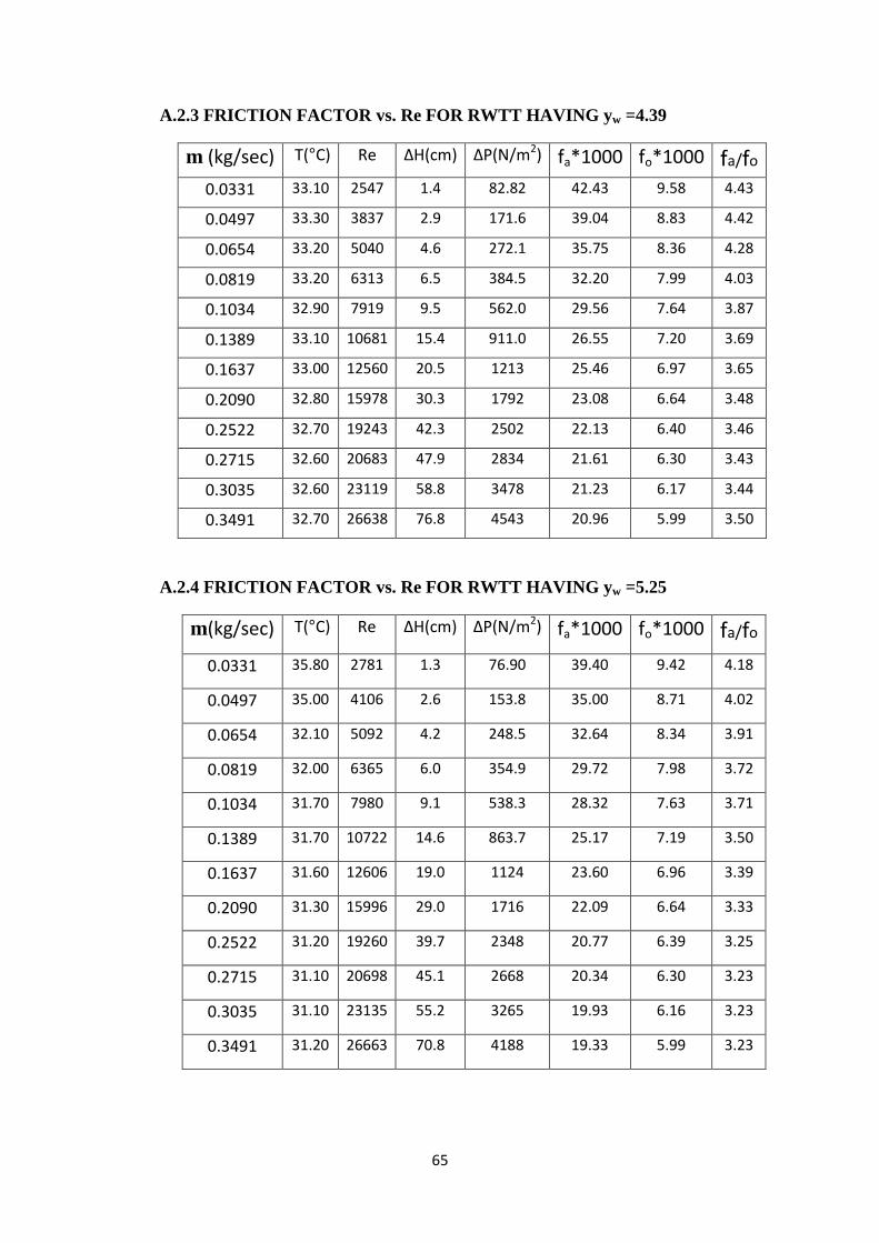
65
A.2.3 FRICTION FACTOR vs. Re FOR RWTT HAVING yw =4.39
m (kg/sec) T(°C) Re ∆H(cm) ∆P(N/m2) fa*1000 fo*1000 fa/fo
0.0331 33.10 2547 1.4 82.82 42.43 9.58 4.43
0.0497 33.30 3837 2.9 171.6 39.04 8.83 4.42
0.0654 33.20 5040 4.6 272.1 35.75 8.36 4.28
0.0819 33.20 6313 6.5 384.5 32.20 7.99 4.03
0.1034 32.90 7919 9.5 562.0 29.56 7.64 3.87
0.1389 33.10 10681 15.4 911.0 26.55 7.20 3.69
0.1637 33.00 12560 20.5 1213 25.46 6.97 3.65
0.2090 32.80 15978 30.3 1792 23.08 6.64 3.48
0.2522 32.70 19243 42.3 2502 22.13 6.40 3.46
0.2715 32.60 20683 47.9 2834 21.61 6.30 3.43
0.3035 32.60 23119 58.8 3478 21.23 6.17 3.44
0.3491 32.70 26638 76.8 4543 20.96 5.99 3.50
A.2.4 FRICTION FACTOR vs. Re FOR RWTT HAVING yw =5.25
m(kg/sec) T(°C) Re ∆H(cm) ∆P(N/m2) fa*1000 fo*1000 fa/fo
0.0331 35.80 2781 1.3 76.90 39.40 9.42 4.18
0.0497 35.00 4106 2.6 153.8 35.00 8.71 4.02
0.0654 32.10 5092 4.2 248.5 32.64 8.34 3.91
0.0819 32.00 6365 6.0 354.9 29.72 7.98 3.72
0.1034 31.70 7980 9.1 538.3 28.32 7.63 3.71
0.1389 31.70 10722 14.6 863.7 25.17 7.19 3.50
0.1637 31.60 12606 19.0 1124 23.60 6.96 3.39
0.2090 31.30 15996 29.0 1716 22.09 6.64 3.33
0.2522 31.20 19260 39.7 2348 20.77 6.39 3.25
0.2715 31.10 20698 45.1 2668 20.34 6.30 3.23
0.3035 31.10 23135 55.2 3265 19.93 6.16 3.23
0.3491 31.20 26663 70.8 4188 19.33 5.99 3.23
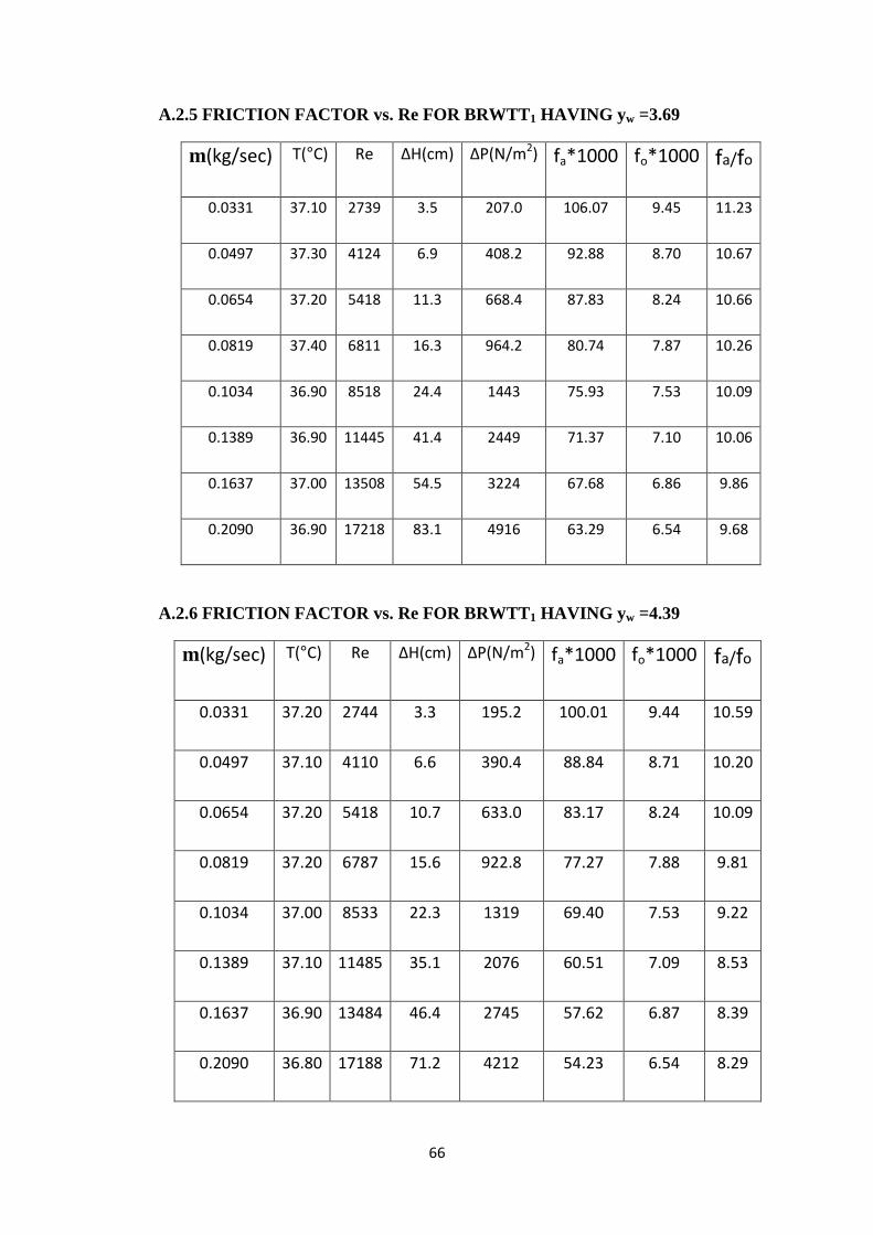
66
A.2.5 FRICTION FACTOR vs. Re FOR BRWTT1 HAVING yw =3.69
m(kg/sec) T(°C) Re ∆H(cm) ∆P(N/m2) fa*1000 fo*1000 fa/fo
0.0331 37.10 2739 3.5 207.0 106.07 9.45 11.23
0.0497 37.30 4124 6.9 408.2 92.88 8.70 10.67
0.0654 37.20 5418 11.3 668.4 87.83 8.24 10.66
0.0819 37.40 6811 16.3 964.2 80.74 7.87 10.26
0.1034 36.90 8518 24.4 1443 75.93 7.53 10.09
0.1389 36.90 11445 41.4 2449 71.37 7.10 10.06
0.1637 37.00 13508 54.5 3224 67.68 6.86 9.86
0.2090 36.90 17218 83.1 4916 63.29 6.54 9.68
A.2.6 FRICTION FACTOR vs. Re FOR BRWTT1 HAVING yw =4.39
m(kg/sec) T(°C) Re ∆H(cm) ∆P(N/m2) fa*1000 fo*1000 fa/fo
0.0331 37.20 2744 3.3 195.2 100.01 9.44 10.59
0.0497 37.10 4110 6.6 390.4 88.84 8.71 10.20
0.0654 37.20 5418 10.7 633.0 83.17 8.24 10.09
0.0819 37.20 6787 15.6 922.8 77.27 7.88 9.81
0.1034 37.00 8533 22.3 1319 69.40 7.53 9.22
0.1389 37.10 11485 35.1 2076 60.51 7.09 8.53
0.1637 36.90 13484 46.4 2745 57.62 6.87 8.39
0.2090 36.80 17188 71.2 4212 54.23 6.54 8.29
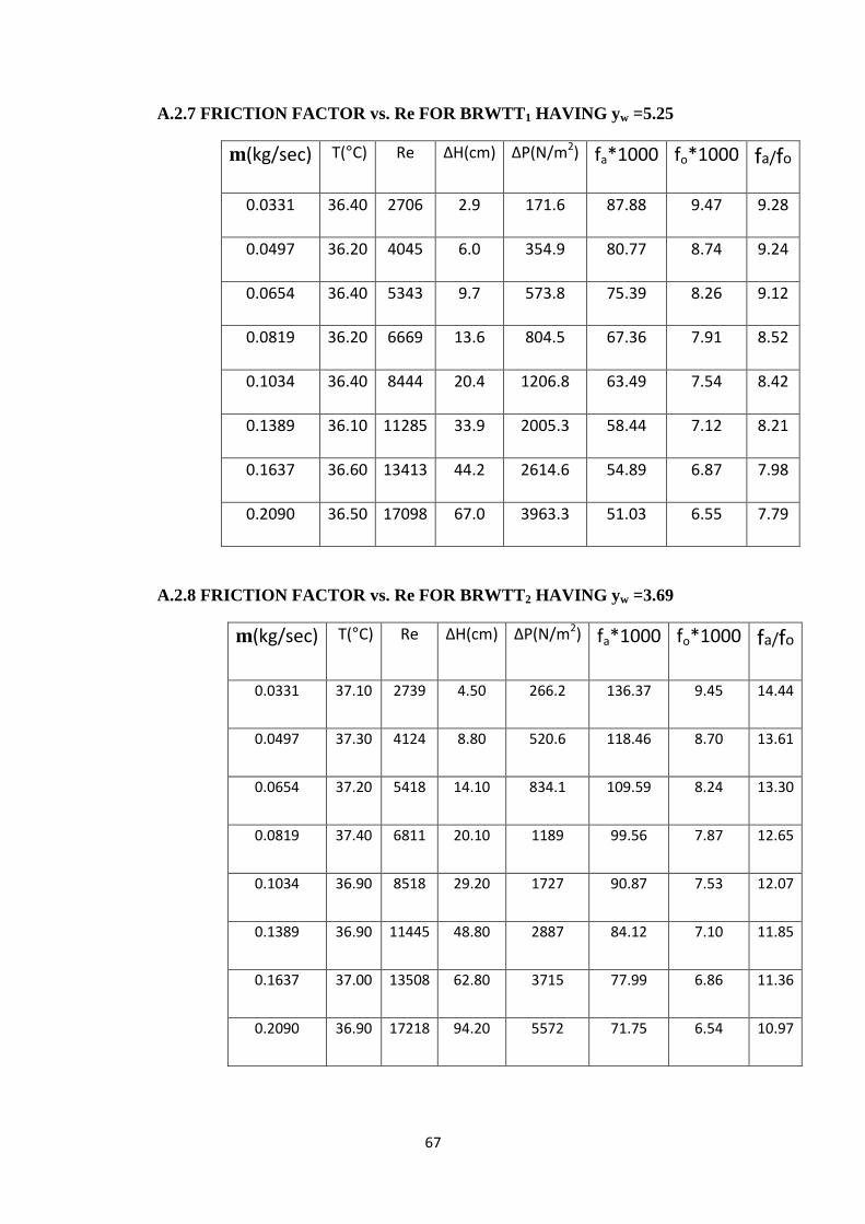
67
A.2.7 FRICTION FACTOR vs. Re FOR BRWTT1 HAVING yw =5.25
m(kg/sec) T(°C) Re ∆H(cm) ∆P(N/m2) fa*1000 fo*1000 fa/fo
0.0331 36.40 2706 2.9 171.6 87.88 9.47 9.28
0.0497 36.20 4045 6.0 354.9 80.77 8.74 9.24
0.0654 36.40 5343 9.7 573.8 75.39 8.26 9.12
0.0819 36.20 6669 13.6 804.5 67.36 7.91 8.52
0.1034 36.40 8444 20.4 1206.8 63.49 7.54 8.42
0.1389 36.10 11285 33.9 2005.3 58.44 7.12 8.21
0.1637 36.60 13413 44.2 2614.6 54.89 6.87 7.98
0.2090 36.50 17098 67.0 3963.3 51.03 6.55 7.79
A.2.8 FRICTION FACTOR vs. Re FOR BRWTT2 HAVING yw =3.69
m(kg/sec) T(°C) Re ∆H(cm) ∆P(N/m2) fa*1000 fo*1000 fa/fo
0.0331 37.10 2739 4.50 266.2 136.37 9.45 14.44
0.0497 37.30 4124 8.80 520.6 118.46 8.70 13.61
0.0654 37.20 5418 14.10 834.1 109.59 8.24 13.30
0.0819 37.40 6811 20.10 1189 99.56 7.87 12.65
0.1034 36.90 8518 29.20 1727 90.87 7.53 12.07
0.1389 36.90 11445 48.80 2887 84.12 7.10 11.85
0.1637 37.00 13508 62.80 3715 77.99 6.86 11.36
0.2090 36.90 17218 94.20 5572 71.75 6.54 10.97
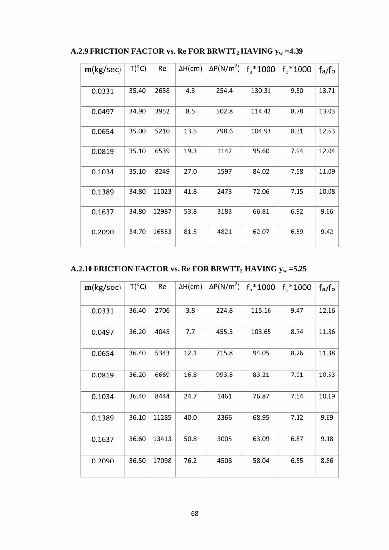
68
A.2.9 FRICTION FACTOR vs. Re FOR BRWTT2 HAVING yw =4.39
m(kg/sec) T(°C) Re ∆H(cm) ∆P(N/m2) fa*1000 fo*1000 fa/fo
0.0331 35.40 2658 4.3 254.4 130.31 9.50 13.71
0.0497 34.90 3952 8.5 502.8 114.42 8.78 13.03
0.0654 35.00 5210 13.5 798.6 104.93 8.31 12.63
0.0819 35.10 6539 19.3 1142 95.60 7.94 12.04
0.1034 35.10 8249 27.0 1597 84.02 7.58 11.09
0.1389 34.80 11023 41.8 2473 72.06 7.15 10.08
0.1637 34.80 12987 53.8 3183 66.81 6.92 9.66
0.2090 34.70 16553 81.5 4821 62.07 6.59 9.42
A.2.10 FRICTION FACTOR vs. Re FOR BRWTT2 HAVING yw =5.25
m(kg/sec) T(°C) Re ∆H(cm) ∆P(N/m2) fa*1000 fo*1000 fa/fo
0.0331 36.40 2706 3.8 224.8 115.16 9.47 12.16
0.0497 36.20 4045 7.7 455.5 103.65 8.74 11.86
0.0654 36.40 5343 12.1 715.8 94.05 8.26 11.38
0.0819 36.20 6669 16.8 993.8 83.21 7.91 10.53
0.1034 36.40 8444 24.7 1461 76.87 7.54 10.19
0.1389 36.10 11285 40.0 2366 68.95 7.12 9.69
0.1637 36.60 13413 50.8 3005 63.09 6.87 9.18
0.2090 36.50 17098 76.2 4508 58.04 6.55 8.86
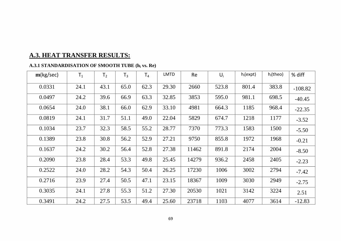
69
A.3. HEAT TRANSFER RESULTS:
A.3.1 STANDARDISATION OF SMOOTH TUBE (hi vs. Re)
m(kg/sec) T1 T2 T3 T4 LMTD Re Ui hi(expt) hi(theo) % diff
0.0331 24.1 43.1 65.0 62.3 29.30 2660 523.8 801.4 383.8 -108.82
0.0497 24.2 39.6 66.9 63.3 32.85 3853 595.0 981.1 698.5 -40.45
0.0654 24.0 38.1 66.0 62.9 33.10 4981 664.3 1185 968.4 -22.35
0.0819 24.1 31.7 51.1 49.0 22.04 5829 674.7 1218 1177 -3.52
0.1034 23.7 32.3 58.5 55.2 28.77 7370 773.3 1583 1500 -5.50
0.1389 23.8 30.8 56.2 52.9 27.21 9750 855.8 1972 1968 -0.21
0.1637 24.2 30.2 56.4 52.8 27.38 11462 891.8 2174 2004 -8.50
0.2090 23.8 28.4 53.3 49.8 25.45 14279 936.2 2458 2405 -2.23
0.2522 24.0 28.2 54.3 50.4 26.25 17230 1006 3002 2794 -7.42
0.2716 23.9 27.4 50.5 47.1 23.15 18367 1009 3030 2949 -2.75
0.3035 24.1 27.8 55.3 51.2 27.30 20530 1021 3142 3224 2.51
0.3491 24.2 27.5 53.5 49.4 25.60 23718 1103 4077 3614 -12.83
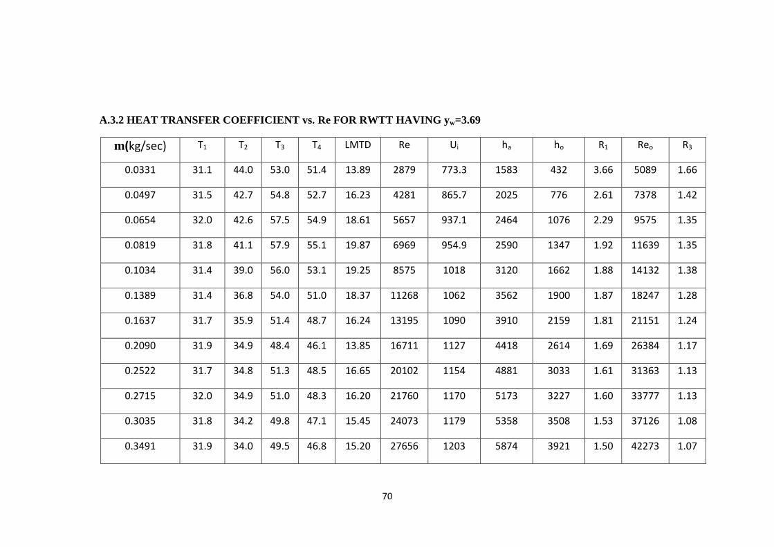
70
A.3.2 HEAT TRANSFER COEFFICIENT vs. Re FOR RWTT HAVING yw=3.69
m(kg/sec) T1 T2 T3 T4 LMTD Re Ui ha ho R1 Reo R3
0.0331 31.1 44.0 53.0 51.4 13.89 2879 773.3 1583 432 3.66 5089 1.66
0.0497 31.5 42.7 54.8 52.7 16.23 4281 865.7 2025 776 2.61 7378 1.42
0.0654 32.0 42.6 57.5 54.9 18.61 5657 937.1 2464 1076 2.29 9575 1.35
0.0819 31.8 41.1 57.9 55.1 19.87 6969 954.9 2590 1347 1.92 11639 1.35
0.1034 31.4 39.0 56.0 53.1 19.25 8575 1018 3120 1662 1.88 14132 1.38
0.1389 31.4 36.8 54.0 51.0 18.37 11268 1062 3562 1900 1.87 18247 1.28
0.1637 31.7 35.9 51.4 48.7 16.24 13195 1090 3910 2159 1.81 21151 1.24
0.2090 31.9 34.9 48.4 46.1 13.85 16711 1127 4418 2614 1.69 26384 1.17
0.2522 31.7 34.8 51.3 48.5 16.65 20102 1154 4881 3033 1.61 31363 1.13
0.2715 32.0 34.9 51.0 48.3 16.20 21760 1170 5173 3227 1.60 33777 1.13
0.3035 31.8 34.2 49.8 47.1 15.45 24073 1179 5358 3508 1.53 37126 1.08
0.3491 31.9 34.0 49.5 46.8 15.20 27656 1203 5874 3921 1.50 42273 1.07
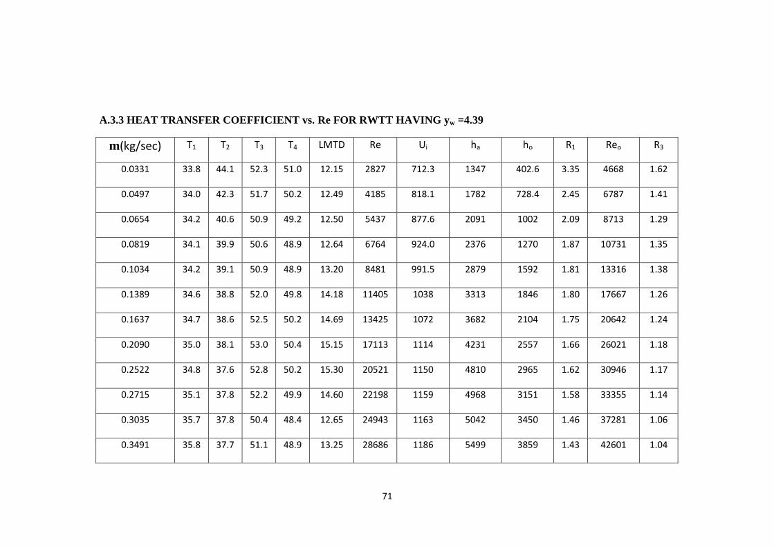
71
A.3.3 HEAT TRANSFER COEFFICIENT vs. Re FOR RWTT HAVING yw =4.39
m(kg/sec) T1 T2 T3 T4 LMTD Re Ui ha ho R1 Reo R3
0.0331 33.8 44.1 52.3 51.0 12.15 2827 712.3 1347 402.6 3.35 4668 1.62
0.0497 34.0 42.3 51.7 50.2 12.49 4185 818.1 1782 728.4 2.45 6787 1.41
0.0654 34.2 40.6 50.9 49.2 12.50 5437 877.6 2091 1002 2.09 8713 1.29
0.0819 34.1 39.9 50.6 48.9 12.64 6764 924.0 2376 1270 1.87 10731 1.35
0.1034 34.2 39.1 50.9 48.9 13.20 8481 991.5 2879 1592 1.81 13316 1.38
0.1389 34.6 38.8 52.0 49.8 14.18 11405 1038 3313 1846 1.80 17667 1.26
0.1637 34.7 38.6 52.5 50.2 14.69 13425 1072 3682 2104 1.75 20642 1.24
0.2090 35.0 38.1 53.0 50.4 15.15 17113 1114 4231 2557 1.66 26021 1.18
0.2522 34.8 37.6 52.8 50.2 15.30 20521 1150 4810 2965 1.62 30946 1.17
0.2715 35.1 37.8 52.2 49.9 14.60 22198 1159 4968 3151 1.58 33355 1.14
0.3035 35.7 37.8 50.4 48.4 12.65 24943 1163 5042 3450 1.46 37281 1.06
0.3491 35.8 37.7 51.1 48.9 13.25 28686 1186 5499 3859 1.43 42601 1.04
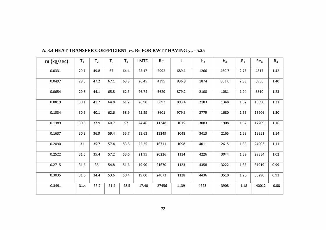
72
A. 3.4 HEAT TRANSFER COEFFICIENT vs. Re FOR RWTT HAVING yw =5.25
m (kg/sec) T1 T2 T3 T4 LMTD Re Ui ha ho R1 Reo R3
0.0331 29.1 49.8 67 64.4 25.17 2992 689.1 1266 460.7 2.75 4817 1.42
0.0497 29.5 47.2 67.1 63.8 26.45 4395 836.9 1874 803.6 2.33 6956 1.40
0.0654 29.8 44.1 65.8 62.3 26.74 5629 879.2 2100 1081 1.94 8810 1.23
0.0819 30.1 41.7 64.8 61.2 26.90 6893 893.4 2183 1348 1.62 10690 1.21
0.1034 30.6 40.1 62.6 58.9 25.29 8601 979.3 2779 1680 1.65 13206 1.30
0.1389 30.8 37.9 60.7 57 24.46 11348 1015 3083 1908 1.62 17209 1.16
0.1637 30.9 36.9 59.4 55.7 23.63 13249 1048 3413 2165 1.58 19951 1.14
0.2090 31 35.7 57.4 53.8 22.25 16711 1098 4011 2615 1.53 24903 1.11
0.2522 31.5 35.4 57.2 53.6 21.95 20226 1114 4226 3044 1.39 29884 1.02
0.2715 31.6 35 54.8 51.6 19.90 21670 1123 4358 3222 1.35 31919 0.99
0.3035 31.6 34.4 53.6 50.4 19.00 24073 1128 4436 3510 1.26 35290 0.93
0.3491 31.4 33.7 51.4 48.5 17.40 27456 1139 4623 3908 1.18 40012 0.88
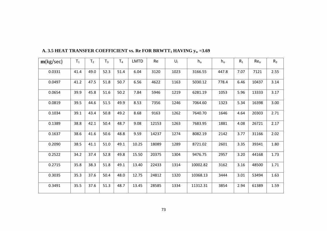
73
A. 3.5 HEAT TRANSFER COEFFICIENT vs. Re FOR BRWTT1 HAVING yw =3.69
m(kg/sec) T1 T2 T3 T4 LMTD Re Ui ha ho R1 Reo R3
0.0331 41.4 49.0 52.3 51.4 6.04 3120 1023 3166.55 447.8 7.07 7121 2.55
0.0497 41.2 47.5 51.8 50.7 6.56 4622 1163 5030.12 778.4 6.46 10437 3.14
0.0654 39.9 45.8 51.6 50.2 7.84 5946 1219 6281.19 1053 5.96 13333 3.17
0.0819 39.5 44.6 51.5 49.9 8.53 7356 1246 7064.60 1323 5.34 16398 3.00
0.1034 39.1 43.4 50.8 49.2 8.68 9163 1262 7640.70 1646 4.64 20303 2.71
0.1389 38.8 42.1 50.4 48.7 9.08 12153 1263 7683.95 1881 4.08 26721 2.17
0.1637 38.6 41.6 50.6 48.8 9.59 14237 1274 8082.19 2142 3.77 31166 2.02
0.2090 38.5 41.1 51.0 49.1 10.25 18089 1289 8721.02 2601 3.35 39341 1.80
0.2522 34.2 37.4 52.8 49.8 15.50 20375 1304 9476.75 2957 3.20 44168 1.73
0.2715 35.8 38.3 51.8 49.1 13.40 22433 1314 10002.82 3162 3.16 48500 1.71
0.3035 35.3 37.6 50.4 48.0 12.75 24812 1320 10368.13 3444 3.01 53494 1.63
0.3491 35.5 37.6 51.3 48.7 13.45 28585 1334 11312.31 3854 2.94 61389 1.59
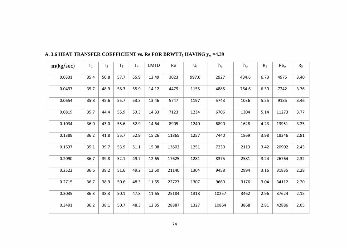
74
A. 3.6 HEAT TRANSFER COEFFICIENT vs. Re FOR BRWTT1 HAVING yw =4.39
m(kg/sec) T1 T2 T3 T4 LMTD Re Ui ha ho R1 Reo R3
0.0331 35.4 50.8 57.7 55.9 12.49 3023 997.0 2927 434.6 6.73 4975 3.40
0.0497 35.7 48.9 58.3 55.9 14.12 4479 1155 4885 764.6 6.39 7242 3.76
0.0654 35.8 45.6 55.7 53.3 13.46 5747 1197 5743 1036 5.55 9185 3.46
0.0819 35.7 44.4 55.9 53.3 14.33 7123 1234 6706 1304 5.14 11273 3.77
0.1034 36.0 43.0 55.6 52.9 14.64 8905 1240 6890 1628 4.23 13951 3.25
0.1389 36.2 41.8 55.7 52.9 15.26 11865 1257 7440 1869 3.98 18346 2.81
0.1637 35.1 39.7 53.9 51.1 15.08 13602 1251 7230 2113 3.42 20902 2.43
0.2090 36.7 39.8 52.1 49.7 12.65 17625 1281 8375 2581 3.24 26764 2.32
0.2522 36.6 39.2 51.6 49.2 12.50 21140 1304 9458 2994 3.16 31835 2.28
0.2715 36.7 38.9 50.6 48.3 11.65 22727 1307 9660 3176 3.04 34112 2.20
0.3035 36.3 38.3 50.1 47.8 11.65 25184 1318 10257 3462 2.96 37624 2.15
0.3491 36.2 38.1 50.7 48.3 12.35 28887 1327 10864 3868 2.81 42886 2.05
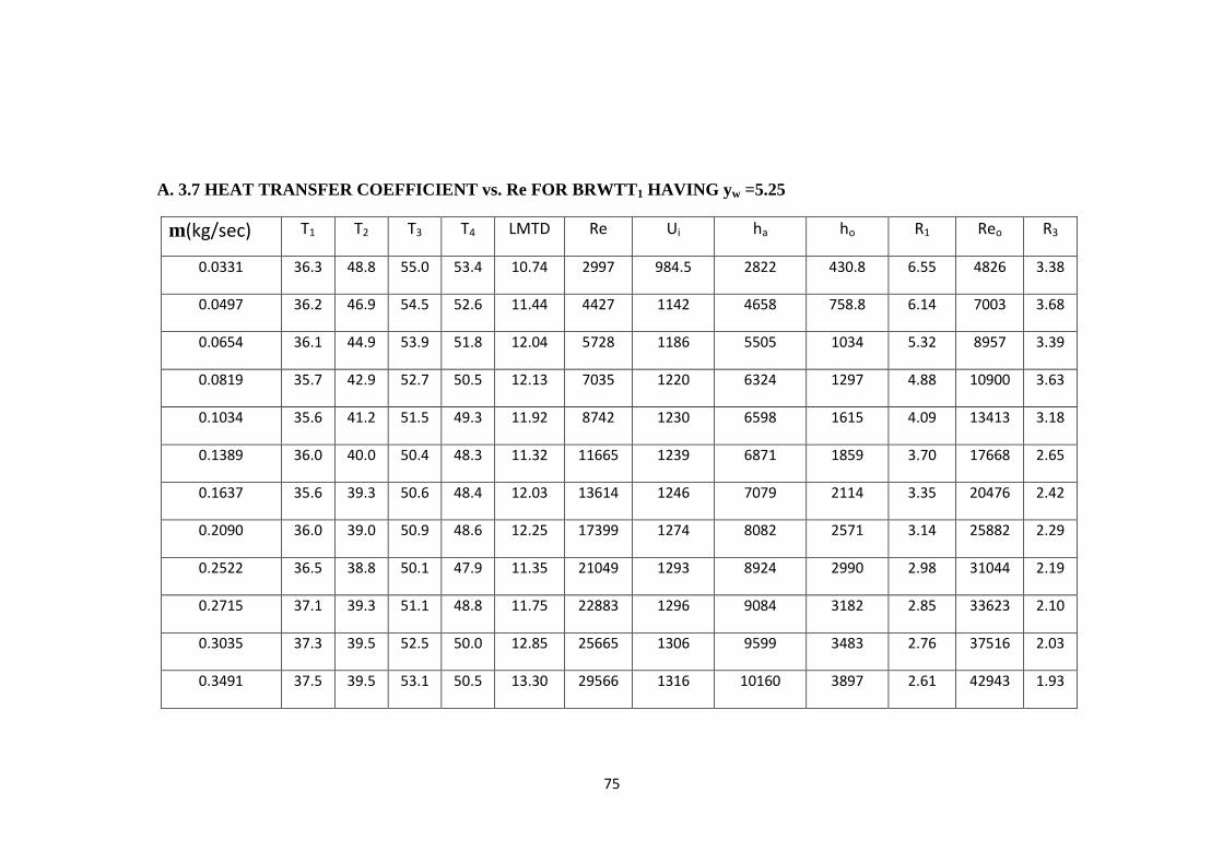
75
A. 3.7 HEAT TRANSFER COEFFICIENT vs. Re FOR BRWTT1 HAVING yw =5.25
m(kg/sec) T1 T2 T3 T4 LMTD Re Ui ha ho R1 Reo R3
0.0331 36.3 48.8 55.0 53.4 10.74 2997 984.5 2822 430.8 6.55 4826 3.38
0.0497 36.2 46.9 54.5 52.6 11.44 4427 1142 4658 758.8 6.14 7003 3.68
0.0654 36.1 44.9 53.9 51.8 12.04 5728 1186 5505 1034 5.32 8957 3.39
0.0819 35.7 42.9 52.7 50.5 12.13 7035 1220 6324 1297 4.88 10900 3.63
0.1034 35.6 41.2 51.5 49.3 11.92 8742 1230 6598 1615 4.09 13413 3.18
0.1389 36.0 40.0 50.4 48.3 11.32 11665 1239 6871 1859 3.70 17668 2.65
0.1637 35.6 39.3 50.6 48.4 12.03 13614 1246 7079 2114 3.35 20476 2.42
0.2090 36.0 39.0 50.9 48.6 12.25 17399 1274 8082 2571 3.14 25882 2.29
0.2522 36.5 38.8 50.1 47.9 11.35 21049 1293 8924 2990 2.98 31044 2.19
0.2715 37.1 39.3 51.1 48.8 11.75 22883 1296 9084 3182 2.85 33623 2.10
0.3035 37.3 39.5 52.5 50.0 12.85 25665 1306 9599 3483 2.76 37516 2.03
0.3491 37.5 39.5 53.1 50.5 13.30 29566 1316 10160 3897 2.61 42943 1.93
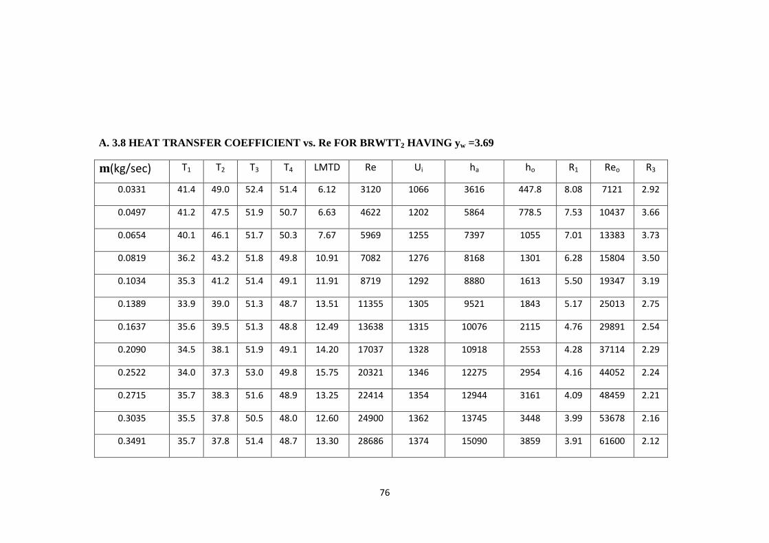
76
A. 3.8 HEAT TRANSFER COEFFICIENT vs. Re FOR BRWTT2 HAVING yw =3.69
m(kg/sec) T1 T2 T3 T4 LMTD Re Ui ha ho R1 Reo R3
0.0331 41.4 49.0 52.4 51.4 6.12 3120 1066 3616 447.8 8.08 7121 2.92
0.0497 41.2 47.5 51.9 50.7 6.63 4622 1202 5864 778.5 7.53 10437 3.66
0.0654 40.1 46.1 51.7 50.3 7.67 5969 1255 7397 1055 7.01 13383 3.73
0.0819 36.2 43.2 51.8 49.8 10.91 7082 1276 8168 1301 6.28 15804 3.50
0.1034 35.3 41.2 51.4 49.1 11.91 8719 1292 8880 1613 5.50 19347 3.19
0.1389 33.9 39.0 51.3 48.7 13.51 11355 1305 9521 1843 5.17 25013 2.75
0.1637 35.6 39.5 51.3 48.8 12.49 13638 1315 10076 2115 4.76 29891 2.54
0.2090 34.5 38.1 51.9 49.1 14.20 17037 1328 10918 2553 4.28 37114 2.29
0.2522 34.0 37.3 53.0 49.8 15.75 20321 1346 12275 2954 4.16 44052 2.24
0.2715 35.7 38.3 51.6 48.9 13.25 22414 1354 12944 3161 4.09 48459 2.21
0.3035 35.5 37.8 50.5 48.0 12.60 24900 1362 13745 3448 3.99 53678 2.16
0.3491 35.7 37.8 51.4 48.7 13.30 28686 1374 15090 3859 3.91 61600 2.12
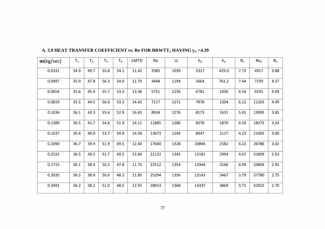
77
A. 3.9 HEAT TRANSFER COEFFICIENT vs. Re FOR BRWTT2 HAVING yw =4.39
m(kg/sec) T1 T2 T3 T4 LMTD Re Ui ha ho R1 Reo R3
0.0331 34.9 49.7 55.8 54.1 11.42 2985 1039 3317 429.0 7.73 4917 3.88
0.0497 35.9 47.8 56.3 54.0 12.70 4448 1194 5664 761.2 7.44 7193 4.37
0.0654 35.6 45.9 55.7 53.3 13.36 5751 1236 6781 1036 6.54 9192 4.09
0.0819 35.5 44.5 56.0 53.3 14.42 7117 1271 7978 1304 6.12 11265 4.49
0.1034 36.1 43.3 55.6 52.9 14.43 8934 1276 8173 1631 5.01 13995 3.85
0.1389 36.5 41.7 54.6 51.9 14.11 11885 1286 8578 1870 4.59 18375 3.24
0.1637 35.4 40.0 53.7 50.9 14.58 13673 1294 8947 2117 4.23 21005 3.00
0.2090 36.7 39.9 51.9 49.5 12.40 17640 1328 10894 2582 4.22 26786 3.02
0.2522 36.5 39.2 51.7 49.2 12.60 21122 1345 12181 2994 4.07 31809 2.93
0.2715 36.1 38.4 50.2 47.8 11.75 22512 1354 12944 3166 4.09 33804 2.95
0.3035 36.5 38.6 50.6 48.2 11.85 25294 1356 13143 3467 3.79 37780 2.75
0.3491 36.2 38.2 51.0 48.5 12.55 28913 1368 14337 3869 3.71 42922 2.70
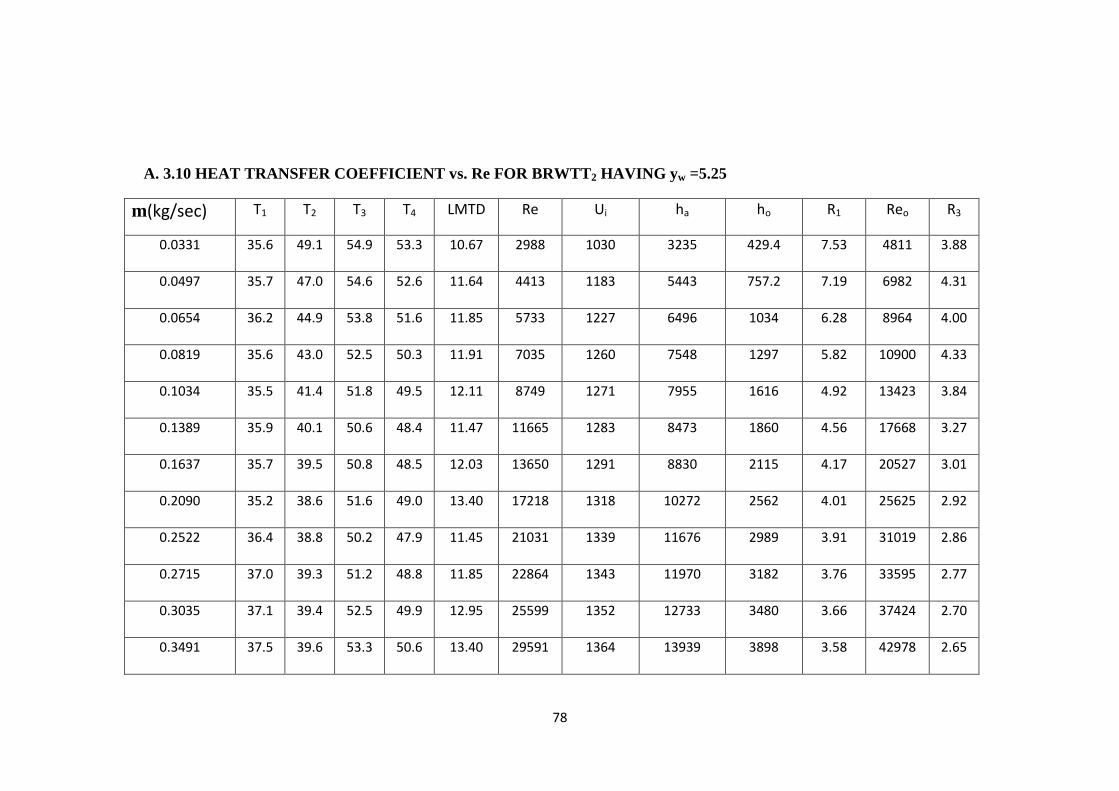
78
A. 3.10 HEAT TRANSFER COEFFICIENT vs. Re FOR BRWTT2 HAVING yw =5.25
m(kg/sec) T1 T2 T3 T4 LMTD Re Ui ha ho R1 Reo R3
0.0331 35.6 49.1 54.9 53.3 10.67 2988 1030 3235 429.4 7.53 4811 3.88
0.0497 35.7 47.0 54.6 52.6 11.64 4413 1183 5443 757.2 7.19 6982 4.31
0.0654 36.2 44.9 53.8 51.6 11.85 5733 1227 6496 1034 6.28 8964 4.00
0.0819 35.6 43.0 52.5 50.3 11.91 7035 1260 7548 1297 5.82 10900 4.33
0.1034 35.5 41.4 51.8 49.5 12.11 8749 1271 7955 1616 4.92 13423 3.84
0.1389 35.9 40.1 50.6 48.4 11.47 11665 1283 8473 1860 4.56 17668 3.27
0.1637 35.7 39.5 50.8 48.5 12.03 13650 1291 8830 2115 4.17 20527 3.01
0.2090 35.2 38.6 51.6 49.0 13.40 17218 1318 10272 2562 4.01 25625 2.92
0.2522 36.4 38.8 50.2 47.9 11.45 21031 1339 11676 2989 3.91 31019 2.86
0.2715 37.0 39.3 51.2 48.8 11.85 22864 1343 11970 3182 3.76 33595 2.77
0.3035 37.1 39.4 52.5 49.9 12.95 25599 1352 12733 3480 3.66 37424 2.70
0.3491 37.5 39.6 53.3 50.6 13.40 29591 1364 13939 3898 3.58 42978 2.65
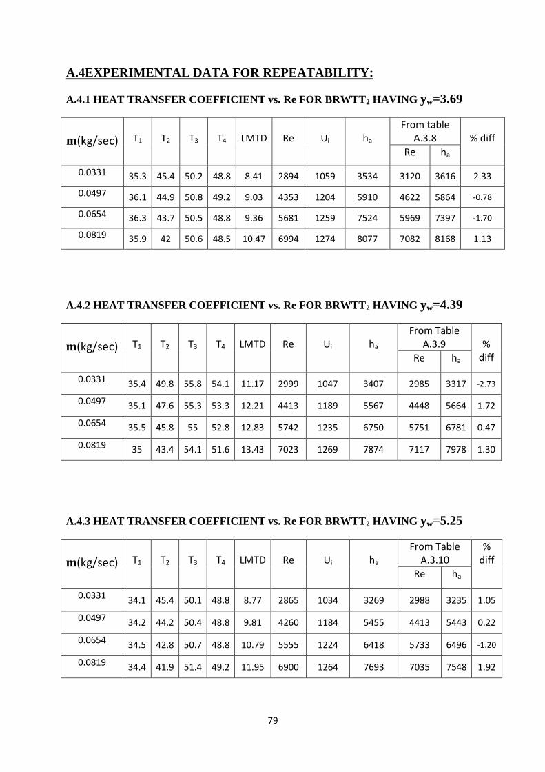
79
A.4EXPERIMENTAL DATA FOR REPEATABILITY:
A.4.1 HEAT TRANSFER COEFFICIENT vs. Re FOR BRWTT2 HAVING yw=3.69
m(kg/sec)
T1
T2
T3
T4
LMTD
Re
Ui
ha
From table A.3.8
% diff
Re ha
0.0331 35.3 45.4 50.2 48.8 8.41 2894 1059 3534 3120 3616 2.33
0.0497 36.1 44.9 50.8 49.2 9.03 4353 1204 5910 4622 5864 -0.78
0.0654 36.3 43.7 50.5 48.8 9.36 5681 1259 7524 5969 7397 -1.70
0.0819 35.9 42 50.6 48.5 10.47 6994 1274 8077 7082 8168 1.13
A.4.2 HEAT TRANSFER COEFFICIENT vs. Re FOR BRWTT2 HAVING yw=4.39
m(kg/sec)
T1
T2
T3
T4
LMTD
Re
Ui
ha
From Table A.3.9
%
diff Re ha
0.0331 35.4 49.8 55.8 54.1 11.17 2999 1047 3407 2985 3317 -2.73
0.0497 35.1 47.6 55.3 53.3 12.21 4413 1189 5567 4448 5664 1.72
0.0654 35.5 45.8 55 52.8 12.83 5742 1235 6750 5751 6781 0.47
0.0819 35 43.4 54.1 51.6 13.43 7023 1269 7874 7117 7978 1.30
A.4.3 HEAT TRANSFER COEFFICIENT vs. Re FOR BRWTT2 HAVING yw=5.25
m(kg/sec)
T1
T2
T3
T4
LMTD
Re
Ui
ha
From Table A.3.10
% diff
Re ha
0.0331 34.1 45.4 50.1 48.8 8.77 2865 1034 3269 2988 3235 1.05
0.0497 34.2 44.2 50.4 48.8 9.81 4260 1184 5455 4413 5443 0.22
0.0654 34.5 42.8 50.7 48.8 10.79 5555 1224 6418 5733 6496 -1.20
0.0819 34.4 41.9 51.4 49.2 11.95 6900 1264 7693 7035 7548 1.92