Embed Size (px)
Citation preview
Mijajlović, M., M.et. al.: Numerical Studies of Parameters Affecting the Heat Generation …
THERMAL SCIENCE, Year 2012, Vol. 16, Suppl. 2, pp. S405-S417 S405
EXPERIMENTAL STUDIES OF PARAMETERS AFFECTING THE HEAT GENERATION IN FRICTION STIR WELDING PROCESS
by
Miroslav M. MIJAJLOVI]*, Nenad T. PAVLOVI], Slobodan V. JOVANOVI], Dragan S. JOVANOVI], and Miodrag D. MIL^I]
Faculty of Mechanical Engineering, University of Niš, Niš, Serbia
Original scientific paper
DOI: 10.2298/TSCI
Heat generation is a complex process of transformation of a specific type of energy into heat. During friction stir welding, one part of mechanical energy delivered to the welding tool is consumed in the welding process, another is used for deformational processes etc., and the rest of the energy is transformed into heat. The analytical procedure for the estimation of heat generated during friction stir welding is very complex because it includes a significant number of variables and parameters, and many of them cannot be fully mathematically explained. Because of that, the analytical model for the estimation of heat generated during friction stir welding defines variables and parameters that dominantly affect heat generation. These parameters are numerous and some of them, e. g. loads, friction coefficient, torque, temperature, are estimated experimentally. Due to the complex geometry of the friction stir welding process and requirements of the measuring equipment, adequate measuring configurations and specific constructional solutions that provide adequate measuring positions are necessary. This paper gives an overview of the process of heat generation during friction stir welding, the most influencing parameters on heat generation, constructional solutions for the measuring equipment needed for these experimental researches and examples of measured values.
Key words: friction stir welding, heat generation, experimental studies
Introduction
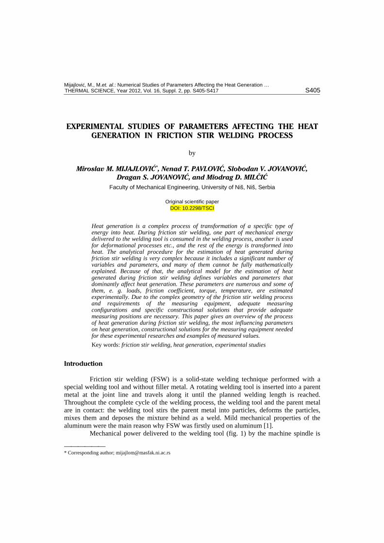
Friction stir welding (FSW) is a solid-state welding technique performed with a special welding tool and without filler metal. A rotating welding tool is inserted into a parent metal at the joint line and travels along it until the planned welding length is reached. Throughout the complete cycle of the welding process, the welding tool and the parent metal are in contact: the welding tool stirs the parent metal into particles, deforms the particles, mixes them and deposes the mixture behind as a weld. Mild mechanical properties of the aluminum were the main reason why FSW was firstly used on aluminum [1].
Mechanical power delivered to the welding tool (fig. 1) by the machine spindle is
* Corresponding author; [email protected]
Mijajlović, M., M.et. al.: Numerical Studies of Parameters Affecting the Heat Generation …
S406 THERMAL SCIENCE, Year 2012, Vol. 16, Suppl. 2, pp. S405-S417
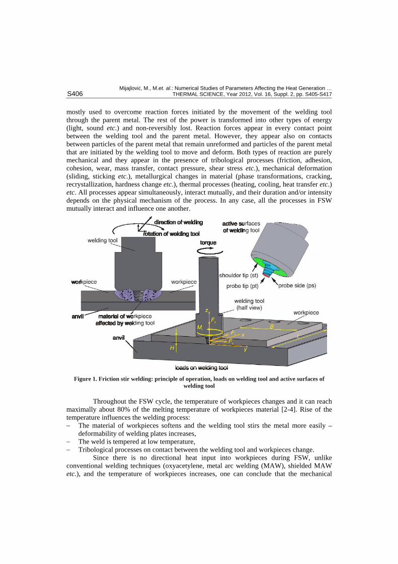
mostly used to overcome reaction forces initiated by the movement of the welding tool through the parent metal. The rest of the power is transformed into other types of energy (light, sound etc.) and non-reversibly lost. Reaction forces appear in every contact point between the welding tool and the parent metal. However, they appear also on contacts between particles of the parent metal that remain unreformed and particles of the parent metal that are initiated by the welding tool to move and deform. Both types of reaction are purely mechanical and they appear in the presence of tribological processes (friction, adhesion, cohesion, wear, mass transfer, contact pressure, shear stress etc.), mechanical deformation (sliding, sticking etc.), metallurgical changes in material (phase transformations, cracking, recrystallization, hardness change etc.), thermal processes (heating, cooling, heat transfer etc.) etc. All processes appear simultaneously, interact mutually, and their duration and/or intensity depends on the physical mechanism of the process. In any case, all the processes in FSW mutually interact and influence one another.
Figure 1. Friction stir welding: principle of operation, loads on welding tool and active surfaces of welding tool
Throughout the FSW cycle, the temperature of workpieces changes and it can reach maximally about 80% of the melting temperature of workpieces material [2-4]. Rise of the temperature influences the welding process: The material of workpieces softens and the welding tool stirs the metal more easily –
deformability of welding plates increases, The weld is tempered at low temperature, Tribological processes on contact between the welding tool and workpieces change.
Since there is no directional heat input into workpieces during FSW, unlike conventional welding techniques (oxyacetylene, metal arc welding (MAW), shielded MAW etc.), and the temperature of workpieces increases, one can conclude that the mechanical
Mijajlović, M., M.et. al.: Numerical Studies of Parameters Affecting the Heat Generation …
THERMAL SCIENCE, Year 2012, Vol. 16, Suppl. 2, pp. S405-S417 S407
energy delivered to the welding tool is significantly transformed into heat. The amount and intensity of heat generation during FSW is the topic of various researches [3-10], and this paper deals with parameters that influence heat generation during FSW.
Parameters affecting heat generation in friction stir welding
In his “Theory of Heat” [11], Maxwell outlines four stipulations for the definition of heat. The second stipulation defines heat as a measurable quantity that can be treated mathematically. Furthermore, the fourth stipulation defines heat as a form of energy, which as such cannot be treated as a substance (the third stipulation). It can be transformed into something that is not a substance (e. g. mechanical work) and it is something that can be transferred from one body to another (the first stipulation) according to the second law of thermodynamics [12]. As a form of energy delivered to a body, heat is, most likely, stored as kinetic and potential energy of atoms and molecules in the body.
Thermodynamics recognizes several different types of heat transfer from a hotter to a cooler body [11, 12]. Both the heat transfer and Maxwell's second stipulation about the quantification of the heat distributed from a body to a body has been investigated for numerous cases. However, a challenge appears when beside pure distribution of heat (from body to body) there exists a process of heat generation on contact between two bodies. Heat generation is a process of energy transformation when one or more forms of energy, due to some conditions, change into heat [12]. This transformation is complex and it depends on the nature of contact between bodies, delivered loads, materials in contact, form of energy given to bodies, surroundings, movement of bodies etc.
Heat generation process at FSW was partially investigated at the beginning of 2002 for the first time [5]. This happened 11 years after the invention of FSW. Reasons for such a late research on heat in FSW lie in the basic principle used for research in FSW: all previous improvements/research of FSW were done following the “trial and error” principle, and the analytical and methodological approach to the heat generation process in FSW was of no interest. To date, three analytical models for estimation and assessment of amount of heat generated during FSW have been published [5, 7, 9]. All of them approach heat generation in FSW in a different manner, however, all of them consider heat generation in FSW as a process tightly connected with the contact mechanics, tribology, plastic deforming and thermodynamics of deformable bodies. The first and second models [5, 7] assume that heat is dominantly generated on the shoulder tip and neglect the heat generated on the probe. These models show that 80%-90% of the mechanical power delivered to the welding tool transforms into heat. The third model [9] considers all active surfaces in the analysis of heat generation and shows that 60%-100% of the mechanical power transforms into heat during FSW.
All of the mentioned analytical models neglect the heat generated due to the translator/axial travel of the welding tool, and the influence of the thread on the probe side, while taking loads on the welding tool from experimental research. The first model [5] assumes that heat is generated due to the pure friction processes, the second model [7] considers deformation and friction in heat generation, while the influence of deformation is equal to the influence of friction. The third model [9] considers friction as the dominant process in heat generation, but it does not neglect deformational heat. All models take friction coefficient as a constant value throughout the complete FSW process and this value is between = 0.3 and = 0.4. Heat transfer from the welding zone into surroundings and
Mijajlović, M., M.et. al.: Numerical Studies of Parameters Affecting the Heat Generation …
S408 THERMAL SCIENCE, Year 2012, Vol. 16, Suppl. 2, pp. S405-S417
workpieces is explained in detail in every model. However, none of the models considers heat transfer initiated by material flow around the welding tool.
The analytical model developed at the Faculty of Mechanical Engineering in Niš is the fourth published model for the estimation of the amount of heat generated during FSW [3, 4, 8]. As well as the first three models, it relies on the postulated conservation of mechanical energy and starts from the assumption that, in theory, the complete amount of mechanical energy delivered to the welding tool transforms into heat. In reality, one part of mechanical energy is used for other processes that appear during welding, which gives that, at most, only the rest of the mechanical energy can be transformed into heat. In order to estimate the maximal possible amount of generated heat during FSW (for certain technological parameters of the process), this model takes into consideration the influence of the welding tool to the process of welding, loads, tribological parameters, temperature of workpieces, material flow around the welding tool, heat generation mechanisms etc.
The number of parameters involving heat generation in FSW is significant and it is difficult to consider all of them in the analysis of the heat generation process. Beside the complexity delivered by numbers, further complexity in understanding the heat generation process in FSW lies in mutual effects between influencing parameters. Therefore, for practical reasons, it is necessary to recognize the dominant parameters that influence the heat generation process, the dominant influences between them and the heat generation process, and then analyze the FSW process and influencing parameters.
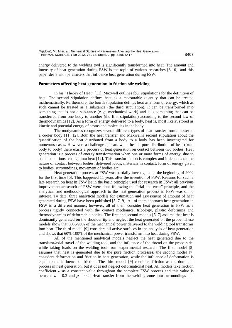
All analytical models for generated heat estimation in FSW, in general, agree that the dominant influencing parameters on the heat generation process are: welding tool geometry, technological parameters of the welding process, delivered loads, tribological parameters (friction coefficient, contact pressure, shear stresses), temperature of workpieces and mechanism of heat generation (friction or deformation).
Figure 2 gives a simplified schematic of mutual dependencies between generated heat and dominant influencing parameters on the heat generation process. Dependencies can be direct or indirect, while direct dependencies can be one-way (for example, AB: parameter A influences parameter B and parameter B does not influence parameter A) or two-way (for example, AB: parameter A influences parameter B and parameter B influences parameter A).
The verification of the fourth analytical model for the estimation of the amount of generated heat in FSW [4] can be
Figure 2. Schematic of mutual dependencies between generated heat and dominant influencing parameters on heat generation [4]
Mijajlović, M., M.et. al.: Numerical Studies of Parameters Affecting the Heat Generation …
THERMAL SCIENCE, Year 2012, Vol. 16, Suppl. 2, pp. S405-S417 S409
done after experimental studies on the FSW process with emphasis on investigation of intensity and character of dominant influencing parameters at various welding conditions.
Experimental studies (welding of plates prepared for experimental research) were performed on plates made of aluminum alloy 2024 T351, dimensions of workpieces: L B H =160 mm 55 mm 6 mm, at welding length of l=100 mm, with the demand to achieve adequate quality of welded joints. Technological parameters of the welding process (tool rotation speed, welding rate etc.) were chosen during the welding process. The selection was done with the goal of reaching optimal technological parameters that provided good quality of welded joints. The complexity of the FSW process required a specific measuring configuration capable of fulfilling demands and it was not possible to use only one universal measuring configuration for all experiments. Due to that fact, different measuring configurations were adopted and prepared.
Influence of the welding tool geometry
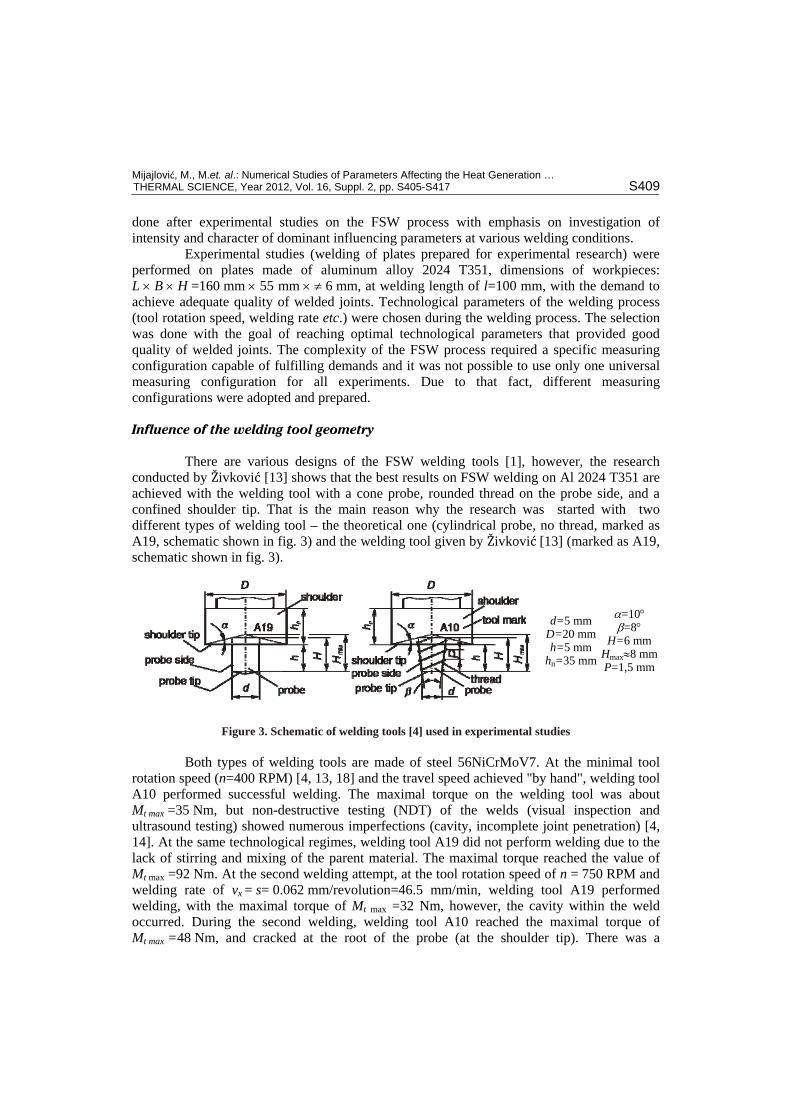
There are various designs of the FSW welding tools [1], however, the research conducted by Živković [13] shows that the best results on FSW welding on Al 2024 T351 are achieved with the welding tool with a cone probe, rounded thread on the probe side, and a confined shoulder tip. That is the main reason why the research was started with two different types of welding tool – the theoretical one (cylindrical probe, no thread, marked as A19, schematic shown in fig. 3) and the welding tool given by Živković [13] (marked as A19, schematic shown in fig. 3).
d=5 mm D=20 mm h=5 mm
hn=35 mm
=10 =8
H=6 mm Hmax8 mmP=1,5 mm
Figure 3. Schematic of welding tools [4] used in experimental studies
Both types of welding tools are made of steel 56NiCrMoV7. At the minimal tool rotation speed (n=400 RPM) [4, 13, 18] and the travel speed achieved "by hand", welding tool A10 performed successful welding. The maximal torque on the welding tool was about Mt max =35 Nm, but non-destructive testing (NDT) of the welds (visual inspection and ultrasound testing) showed numerous imperfections (cavity, incomplete joint penetration) [4, 14]. At the same technological regimes, welding tool A19 did not perform welding due to the lack of stirring and mixing of the parent material. The maximal torque reached the value of Mt max =92 Nm. At the second welding attempt, at the tool rotation speed of n = 750 RPM and welding rate of vx = s= 0.062 mm/revolution=46.5 mm/min, welding tool A19 performed welding, with the maximal torque of Mt max =32 Nm, however, the cavity within the weld occurred. During the second welding, welding tool A10 reached the maximal torque of Mt max =48 Nm, and cracked at the root of the probe (at the shoulder tip). There was a
Mijajlović, M., M.et. al.: Numerical Studies of Parameters Affecting the Heat Generation …
S410 THERMAL SCIENCE, Year 2012, Vol. 16, Suppl. 2, pp. S405-S417
suspicion that welding tool A10 was of poor quality, and the experiment was performed again with a new A10 tool, with the same technological parameters. Welding could not be performed and the welding tool cracked once more at the same place as the first welding tool, at the maximal torque of Mt max=45 Nm. It was concluded, as in ref. [13], that the welding tool without thread on the probe cannot perform welding on Al 2024 T351. Further experiments included only welding tool A10 (fig. 3).
Influence of the technological parameters of the welding process
The experimental research commenced with the recommended diapason of the technological parameters of the FSW process [13, 4]. Optimal values of technological parameters, that gave good quality of welds, were reached after eight repetitions. These values are shown in tab. 1.
Table 1. Proposed technological parameters for welding of Al 2024 T351 [4]
Recommended diapason/value Optimal values Tool rotation speed n = 750-1180 RPM n = 910 RPM
Plunging speed vz – no recommended value vz – not determined Travel speed vx = 46-150 mm/min = 0.77-2.5 mm/s vx = 0.062 mm/rev. = 0.9403 mm/s
Tilt angle 5 1-2 Welding length l = 50 mm l 100 mm
Due to the fact that technological parameters of the FSW involve other parameters of the FSW process, it is very difficult to give detailed conclusions about a pure and separate influence of technological parameters on the heat generation process regardless of other parameters that are involved in the process. However, there are conclusions about the quality of the welds on Al 2024 T31 alloy connected with the technological parameters: At lower tool rotation speeds, regardless of the travel speed, cavities and cracking appear
more often than at higher values of the tool rotation speeds; Low travel speed increases the sticking of the parent metal to the welding tool, which
significantly decreases the mixing of the material; Rotation direction of the welding tool should be selected in a manner that the thread
travels to the root of the weld resulting in better penetration and full welding of the weld root;
Loads of welding tool are influenced by the technological parameters of the process.
Influence of the loads
Superposition of all resistances to the movement of the welding tool is not simple because the welding tool travels complexly – it rotates constantly and travels transversally. Furthermore, loads/resistances to the movement of the welding tool appear due to the material flow around the welding tool, too (fig. 1). The most common loads-superposition model shows all loads as one force and one momentum. For simpler understanding, force is resolved in three directions (along the axis of rotation, along the joint line, perpendicular to the joint line) and the vector of momentum is considered to be in the direction of the rotation axis, directed oppositely to the rotation of the welding tool (fig. 1).
Mijajlović, M., M.et. al.: Numerical Studies of Parameters Affecting the Heat Generation …
THERMAL SCIENCE, Year 2012, Vol. 16, Suppl. 2, pp. S405-S417 S411
Loads delivered by the welding tool affect stress-strain conditions of workpieces, as well as the welding process itself. In general, it can be concluded that the increase in loads intensity manifests in greater heat generation rate and more intensive rise of workpiece temperature. Complex kinematics of the FSW process and the need to have heavy-duty clamped workpieces during the FSW process, in general, make the process of measuring the intensity of load challenging.
Experimental study of the torque and axial force
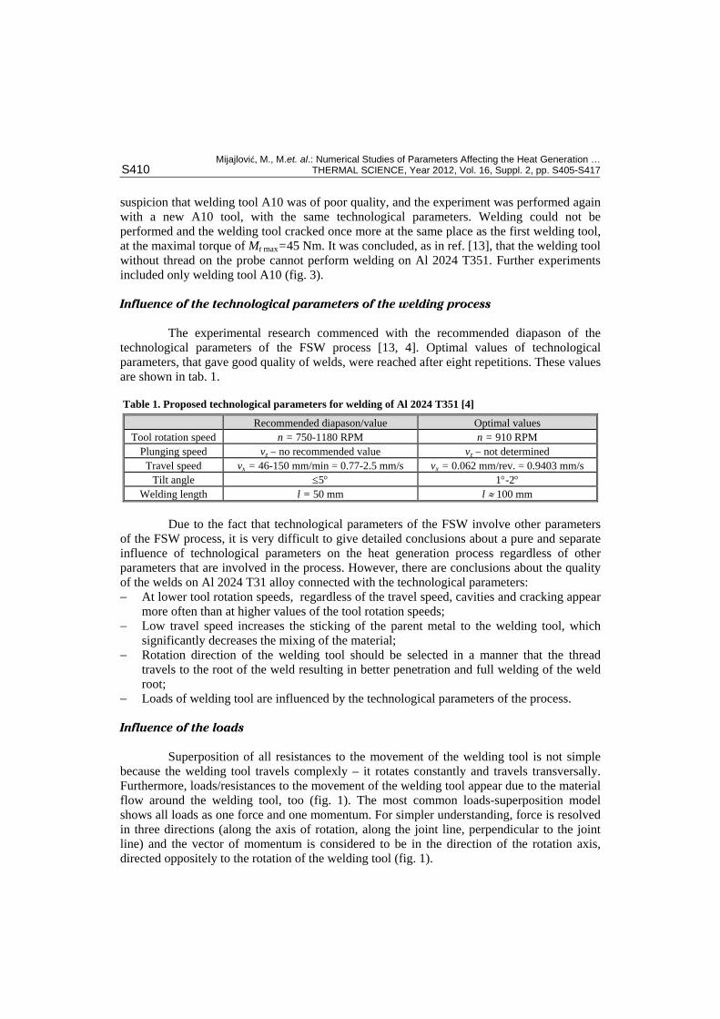
Experimental estimation or measuring the torque delivered to the welding tool is done by mounting the torque sensor (load cell) on the shaft that transmits power from the machine spindle to the welding tool. The axial force from the contact between the welding tool and workpieces should not be delivered to the torque sensor due to its sensitivity to forces. The axial force is measured behind the workpieces and the anvil. Figure 4 shows the experimental measuring configuration used for the estimation of experimental torque and axial force. It is an unusual configuration for the FSW process because the axis of the welding tool is horizontal.
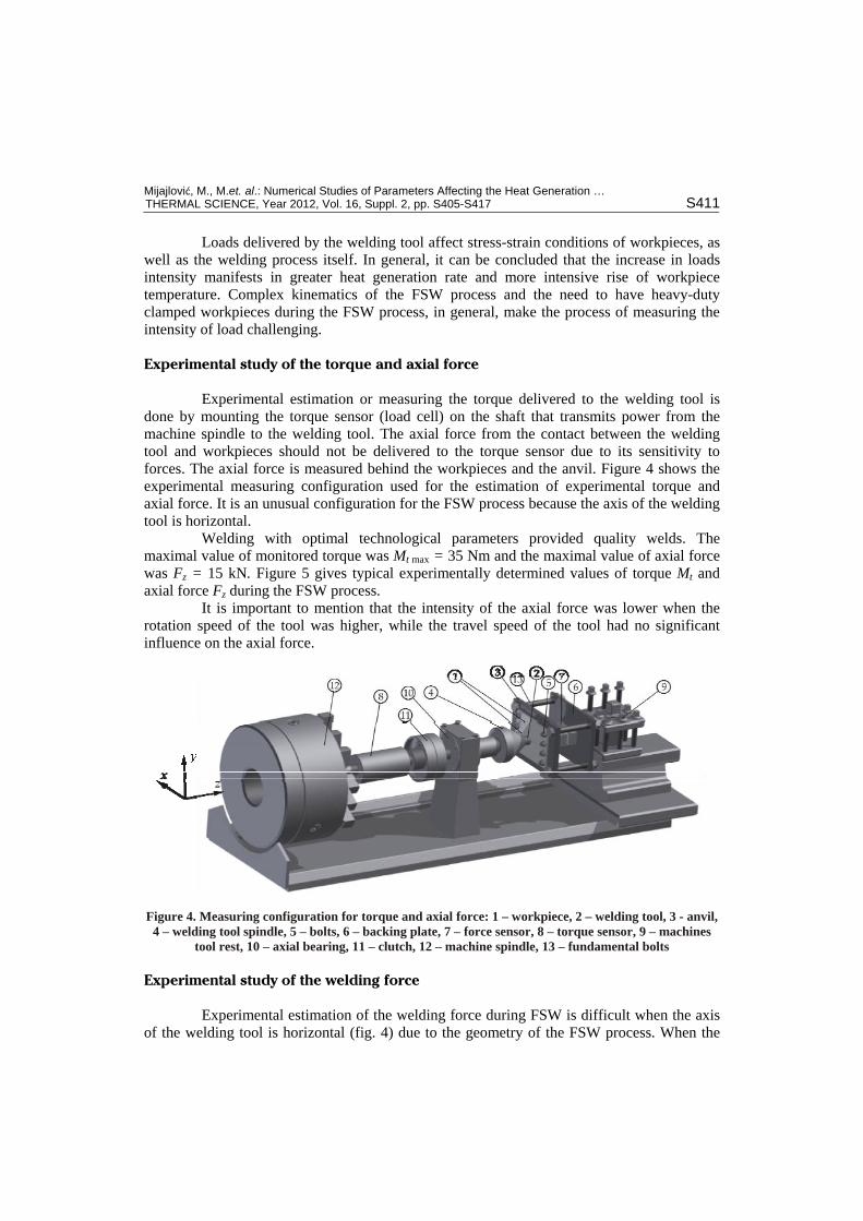
Welding with optimal technological parameters provided quality welds. The maximal value of monitored torque was Mt max = 35 Nm and the maximal value of axial force was Fz = 15 kN. Figure 5 gives typical experimentally determined values of torque Mt and axial force Fz during the FSW process.
It is important to mention that the intensity of the axial force was lower when the rotation speed of the tool was higher, while the travel speed of the tool had no significant influence on the axial force.
Figure 4. Measuring configuration for torque and axial force: 1 – workpiece, 2 – welding tool, 3 - anvil, 4 – welding tool spindle, 5 – bolts, 6 – backing plate, 7 – force sensor, 8 – torque sensor, 9 – machines
tool rest, 10 – axial bearing, 11 – clutch, 12 – machine spindle, 13 – fundamental bolts
Experimental study of the welding force
Experimental estimation of the welding force during FSW is difficult when the axis of the welding tool is horizontal (fig. 4) due to the geometry of the FSW process. When the
Mijajlović, M., M.et. al.: Numerical Studies of Parameters Affecting the Heat Generation …
S412 THERMAL SCIENCE, Year 2012, Vol. 16, Suppl. 2, pp. S405-S417
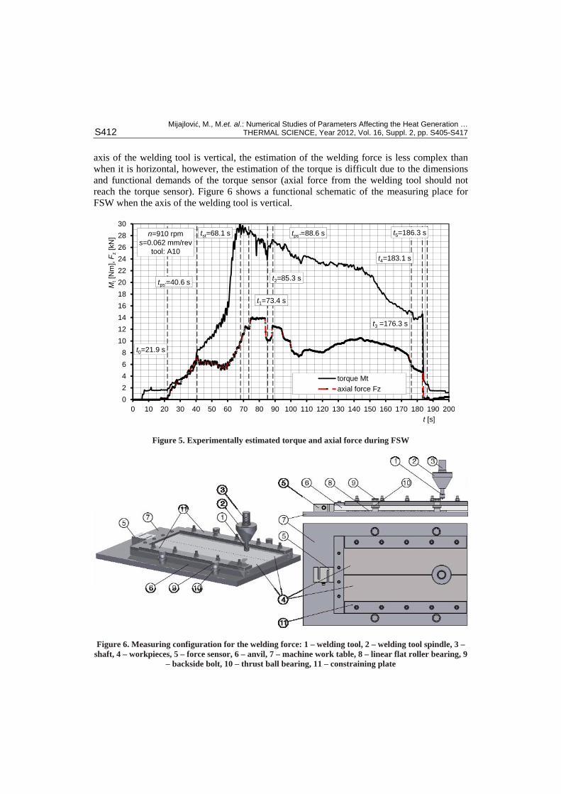
axis of the welding tool is vertical, the estimation of the welding force is less complex than when it is horizontal, however, the estimation of the torque is difficult due to the dimensions and functional demands of the torque sensor (axial force from the welding tool should not reach the torque sensor). Figure 6 shows a functional schematic of the measuring place for FSW when the axis of the welding tool is vertical.
n=910 rpm
s=0.062 mm/rev
tool: A10
t0=21.9 s
t1=73.4 s
t2=85.3 s
t3
=176.3 s
t4=183.1 s
tst=68.1 s
tps'
=40.6 s
tps"
=88.6 s t5=186.3 s
0
2
4
6
8
10
12
14
16
18
20
22
24
26
28
30
0 10 20 30 40 50 60 70 80 90 100 110 120 130 140 150 160 170 180 190 200
Mt[N
m], F
z[kN
]
t [s]
torque Mt
axial force Fz
Figure 5. Experimentally estimated torque and axial force during FSW
Figure 6. Measuring configuration for the welding force: 1 – welding tool, 2 – welding tool spindle, 3 – shaft, 4 – workpieces, 5 – force sensor, 6 – anvil, 7 – machine work table, 8 – linear flat roller bearing, 9
– backside bolt, 10 – thrust ball bearing, 11 – constraining plate
Mijajlović, M., M.et. al.: Numerical Studies of Parameters Affecting the Heat Generation …
THERMAL SCIENCE, Year 2012, Vol. 16, Suppl. 2, pp. S405-S417 S413
Experimental studies showed that the tool rotation speed did not influence the welding force to a great extent, however, the travel speed dominantly influenced the intensity of the welding force. At the maximal suggested welding speed (travel speed) of vx=2.5 mm/s, the maximal welding force reached Fxmax=510 N at the moment when the welding phase started (t3). At the minimal travel speed of vx=0.77 mm/s the welding force reached the intensity of Fxmax=470 N. For the travel rate between the maximum and the minimum, the intensity of the maximal welding force was between 470 N and 508 N. It is obvious that the intensity of the welding force is many times smaller than the intensity of the axial force.
Experimental estimation of the friction coefficient
The majority of of published research on FSW confirms the complexity of the friction processes in FSW. Many of them recognize the problem of the estimation of the friction coefficient, however, they neglect it and consider the friction coefficient to be constant, taking the value of = 0.3-0.4 [1, 5, 7, 10].
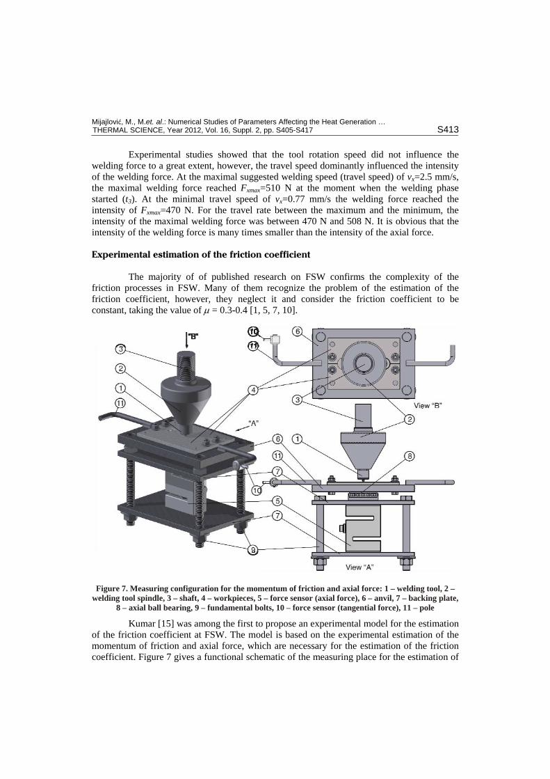
Figure 7. Measuring configuration for the momentum of friction and axial force: 1 – welding tool, 2 – welding tool spindle, 3 – shaft, 4 – workpieces, 5 – force sensor (axial force), 6 – anvil, 7 – backing plate,
8 – axial ball bearing, 9 – fundamental bolts, 10 – force sensor (tangential force), 11 – pole
Kumar [15] was among the first to propose an experimental model for the estimation of the friction coefficient at FSW. The model is based on the experimental estimation of the momentum of friction and axial force, which are necessary for the estimation of the friction coefficient. Figure 7 gives a functional schematic of the measuring place for the estimation of
Mijajlović, M., M.et. al.: Numerical Studies of Parameters Affecting the Heat Generation …
S414 THERMAL SCIENCE, Year 2012, Vol. 16, Suppl. 2, pp. S405-S417
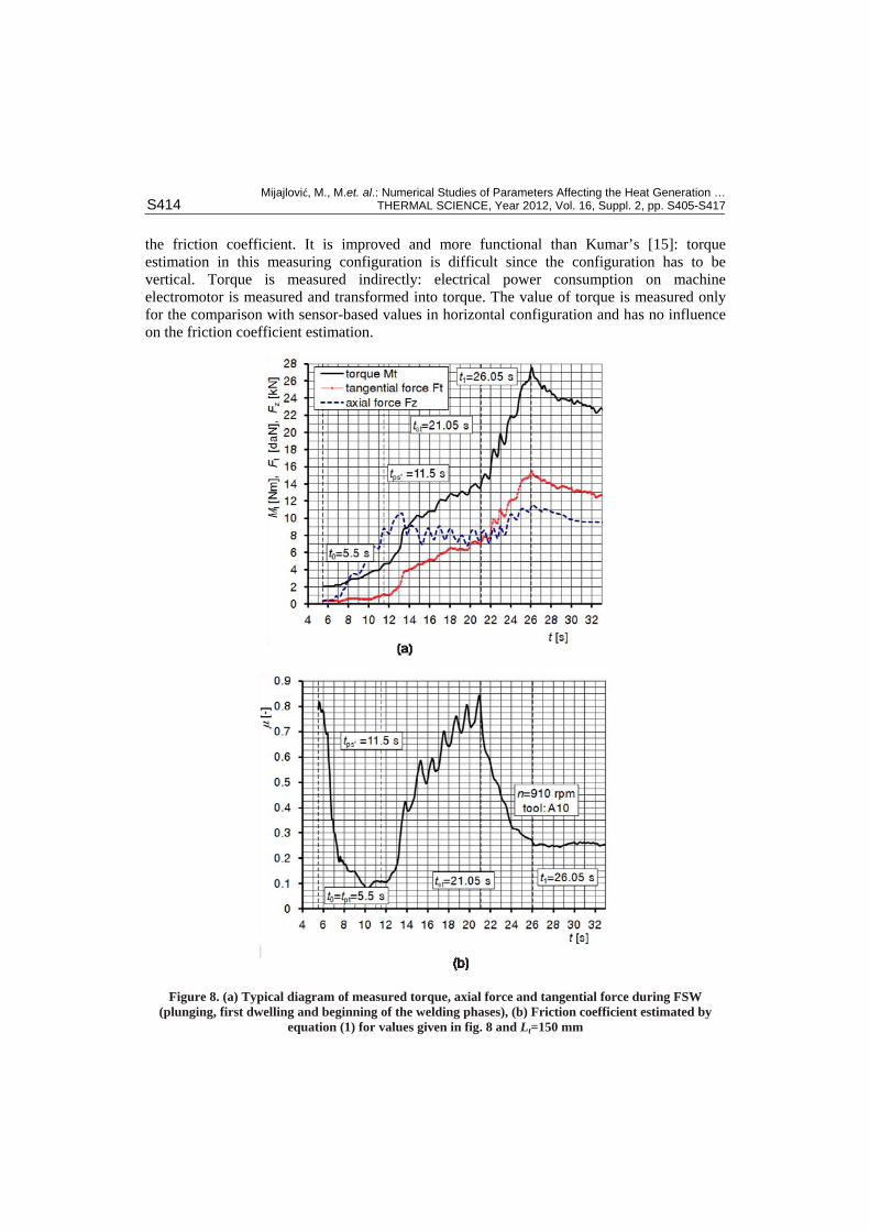
the friction coefficient. It is improved and more functional than Kumar’s [15]: torque estimation in this measuring configuration is difficult since the configuration has to be vertical. Torque is measured indirectly: electrical power consumption on machine electromotor is measured and transformed into torque. The value of torque is measured only for the comparison with sensor-based values in horizontal configuration and has no influence on the friction coefficient estimation.
Figure 8. (a) Typical diagram of measured torque, axial force and tangential force during FSW (plunging, first dwelling and beginning of the welding phases), (b) Friction coefficient estimated by
equation (1) for values given in fig. 8 and Lt=150 mm
Mijajlović, M., M.et. al.: Numerical Studies of Parameters Affecting the Heat Generation …
THERMAL SCIENCE, Year 2012, Vol. 16, Suppl. 2, pp. S405-S417 S415
To estimate the coefficient of friction at FSW, it is necessary to estimate the momentum of friction and axial force. The momentum of friction is a multiplication of the tangential force Ft (measured at force sensor 10, fig. 7) and length of the force pole (friction pole) Lt. If the diameter of the welding tool probe in contact is d, friction coefficient can be estimated as [15-17]:
3 t
z
F L
F d (1)
Equation (1) is approximate and due to the design limitations of the FSW process applicable only to plunging, first dwelling and beginning of the welding phases [4]. However, even approximate, it provides some results that are better than the ad hoc adopted values of the friction coefficient. Figure 8 gives typical diagrams of measured values necessary for the estimation of the friction coefficient and torque.
The experimental value of the friction coefficient at FSW varies from =0.1 to =1, depending on the stage of the process, technological parameters, temperature etc.
Experimental estimation of the temperature
The estimation of the FSW workpiece and welding tool temperature is an illusively easy-to-do job. Experimental measuring can be obtained by an infrared camera and/or by thermocouples embedded at specific spots in workpieces. The infrared camera catches thermal images of surfaces captured by the camera frame, but the temperatures in the depth of the workpieces and welding tool, as well as the temperature on their contact, cannot be estimated. Thermocouples provide temperatures in the depth of the material, but they require preparation of workpieces, and it is necessary to have more than one thermocouple for a complete thermal image of the material.
For the purpose of the analytical estimation of the amount of heat generated during FSW, it is important to have the temperature of the material around the welding tool while it travels along the joint line. Satisfactory measuring results applicable in the analytical model [4] can be obtained by the infrared camera and there is no need for any preparation of workpieces.
Experimental study on temperature at FSW by the infrared camera showed the maximal temperatures of Tmax = 394 C at workpieces and Tmax = 464 C on the welding tool, both on the vertical and the horizontal measuring configurations.
Discussion and conclusions
The analytical model for the estimation of the amount of heat generated during FSW, developed at the Faculty of Mechanical Engineering in Niš, uses complex and multi-run procedures to find how much mechanical power is transformed into heat. The complexity of the model is multilateral: mathematical formulations for the process description are relatively simple, but dependencies between the involved parameters are complex and difficult to describe mathematically. That is another level of the complexity of the model: it must rely on experimental data obtained during experimental studies and implement this information into its routines.
Mijajlović, M., M.et. al.: Numerical Studies of Parameters Affecting the Heat Generation …
S416 THERMAL SCIENCE, Year 2012, Vol. 16, Suppl. 2, pp. S405-S417
To estimate how much mechanical energy transforms into heat during FSW, it is necessary to find what parameters influence heat generation and how much they influence the process. Previous research on FSW has defined the geometry of the welding tool, torque, axial force, tribological parameters of the contact and temperature as dominant parameters involving heat generation in FSW. Experimental studies on these parameters are, for now, the most reliable method to determine their intensity, character (trend) and influence of weld creation and heat generation. The analytical model for the amount of generated heat estimation, in cohesion with the experimental data, gives the most accurate results.
However, experimental studies and measuring intensities and trends of dominant parameters require the application of various measuring devices and specific equipment. Furthermore, specific geometry and kinematics of the FSW process require different measuring configurations and partial measuring: it is not possible to measure all parameters at once. That is the reason why experimental studies last for a long period of time and why there have to be many of them.
Nomenclature
B – width of workpiece, [m] D – diameter of shoulder, [m] Fx – welding force, [N] Fy – force in y direction, [N] Fz – axial force, [N] H – height of workpiece, [m] Hmax – maximal height of probe, [m] L – length of workpiece, [m] Mt – torque, [Nm]P – thread pitch, [m] T – temperature, [C] Qt – generated heat, [W] d – diameter of probe, [m] h – height of probe, [m] hn – height of shoulder, [m] l – welding length, [m] n – rotation speed, [min–1] p – contact pressure, [Nm2] t – time, [s] tdw1 – duration of the first dwelling phase, [s]tdw2 – duration of the sec. dwelling phase, [s]tpo – duration of the pulling out phase, [s]tps' – the moment when probe side engages
into the welding process, [s] tps“ – the moment when welding tool reaches
nominal travel rate, [s]
tst – the moment when the shoulder tipengages into the welding process, [s]
tw – duration of the welding phase, [s] t0 – start of the plunging phase, [s] t1 – end of the plunging phase/start of the
first dwelling phase, [s] t2 – end of the first dwelling phase/start of
the welding phase, [s] t3 – end of the welding phase/start of the
second dwelling phase, [s] t4 – end of the second dwelling phase/start
of the pulling out phase, [s] t5 – end of the pulling out phase, [s] tpl – duration of the plunging phase, [s]
vx – welding tool travel rate, [ms1] vz – plunging speed, [ms1] x, y, z – Descartes coordinates, [m]
Greek symbols
– shoulder cone angle, [] – probe cone angle, [] – contact state variable, [-] yield – yield strength, [Nm2] contact – contact shear stress, [Nm2] – angular velocity, [rads1]
References
[1] Soundararajan, V. et al., An Overview of R&D Work in Friction Stir Welding at SMU, Association of Metallurgical Engineers of Serbia, Journal of Metallurgy, 12 (2006), 204, pp. 277-295
[2] Stamenković, D., Djurdjanović, M., Tribology of the Press Fit Joints, Faculty of Mechanical Engineering Niš, Serbia, 2005
Mijajlović, M., M.et. al.: Numerical Studies of Parameters Affecting the Heat Generation …
THERMAL SCIENCE, Year 2012, Vol. 16, Suppl. 2, pp. S405-S417 S417
[3] Mijajlović, M. et al., Mathematical Model for Analytical Estimation of Generated Heat During Friction Stir Welding. Part 1, Journal of Balkan Tribological Association, 17 (2011), 2, pp. 179-191
[4] Mijajlović, M., Investigation and development of analytical model for estimation of amount of heat generated during FSW, PhD thesis, University of Nis, Faculty of Mechanical Engineering Nis, 2012.
[5] Schmidt, H., et al., An analytical model for the heat generation in Friction Stir Welding, Modeling Simul. Mater. Sci. Eng, 12 (2004), 1, pp. 143-157
[6] Djurdjanović, M. et al., Heat Generation During Friction Stir Welding Process, Tribology in Industry, 31 (2009), 1-2, pp. 8-14
[7] Ulysse, P., Three-dimensional modeling of the friction stir-welding process, Int. J. Mach. Tool. Manu., 42 (2002), pp.1549-1557
[8] Mijajlović, M. et al: Mathematical Model for Analytical Estimation of Generated Heat During Friction Stir Welding. Part 2, Journal of Balkan Tribological Association, 17 (2011), 3, pp. 361-370
[9] Song, M., Kovačević, R., Thermal modeling of friction stir welding in a moving coordinate system and its validation, Int. J. of Machine Tools & Manufacture, 43 (2003), pp. 605-615
[10] Santiago, D., et al., 3-D modelling of material flow and temperature in Friction Stir Welding. Soldag. insp. 14 (2009), pp. 248-256
[11] Maxwell, J.C., Theory of Heat, Dover Publications, Inc., GB, 1871, [12] Ilić, G., Radojković, N., Stojanović I., Thermodynamics II – Basics of the Heat Transport (in Serbian),
Vranje, Yugoslavia, 1996 [13] Živković, A: Influence of friction stir welding tool geometry on properties of welded joint of alloys Al
2024, PhD thesis, University of Belgrade, Faculty of Mechanical Engineering, 2011 [14] ISO 25239-1: 2011 Friction stir welding - Aluminium - Part 1: Vocabulary, [15] Kumar, K. et al: An Investigation of Friction during Friction Stir Welding of Metallic Materials,
Materials and Manufacturing Processes, 24 (2009), 4, pp. 438 - 445 [16] Galin, L. A., Contact Problems; The legacy of L.A. Galin, Series: Solid Mechanics and Its Applications
(in Russian), Nauka, Moscow, Russia, 15 (2008). [17] Mijajlović, M. et al: Study About Friction Coefficient Estimation in Friction Stir Welding, presented at
the Balkantrib 11, The 7th International Conference on Tribology, 3-5 October, 2011, Thessaloniki, Greece, Proceedings, pp 323-330, ISBN 978-960-98780-6-7,
[18] Veljić, D. et al., A Coupled Thermo-Mechanical Model of Friction Stir Welding. Thermal Science, 16 (2012), 2, pp. 527-534, ISSN 0354-9836, doi:10.2298/TSCI110729012V.
Paper submitted: April 30, 2012.
Paper revised: July 26, 2012.
Paper accepted: August 2, 2012.