Embed Size (px)
Citation preview

Supporting information
Haobo Donga, Jianwei Lia, Siyu Zhaoa, Fangjia Zhaoa, Siyu Xionga, Dan J.L. Brettb, Guanjie
He*a, b, c and Ivan P. Parkin*a
aChristopher Ingold Laboratory, Department of Chemistry, University College London, 20
Gordon Street, London WC1H 0AJ, U.K. Email: [email protected]; [email protected]
bElectrochemical Innovation Lab, Department of Chemical Engineering, University College
London, 20 Gordon Street, London WC1H 0AJ, U.K.
cSchool of Chemistry, University of Lincoln, Brayford Pool, Lincoln, LN6 7TS.
Experimental section
Preparation of epoxy-based polymer electrolyte
Zinc triflate with 0.2g was dissolved into polymer PEGDGE, and then the plasticizer PC was added. The complexes were mixed by the magnetic stir for at least 3 hours to obtain a homogeneous transparent solution. Curing agent TETA is added and stirred for an extra 5 minutes after the zinc salt was entirely dissolved in the polymer. The solid polymer film was fabricated by casting with a PTFE mold which was in the disc shape with 15 mm diameter and 1-2 mm thickness. As to ensure the polymer was fully polymerised, the entire polymer was cured at 80 for 24 hours with the heat and cooling rate 3 /min.
Electrode fabrication
For general electrochemical tests, cathode materials were fabricated by casting the commercial active material β-MnO2 on a hydrophilic carbon paper. Super P carbon and polyvinylidene difluoride (PVDF) were mixed with the active material in the weight ratio of 2:1:7. The casted carbon paper was dried in a vacuum oven for 12 h at 70oC. The average mass loading for the dried cathode is 1.5~2.5 mg cm-2. Regarding the anode, zinc metal foil was used after fully polishing to remove the surface ZnO.
In terms of the device, both cathode and anode materials were casted on the woven carbon cloth. The mixture of the electrode materials was in the same ratio as mentioned above, whilst zinc powder is applied instead of the zinc metal. The casted carbon paper was dried in a vacuum oven for 12 h at 70.
Electronic Supplementary Material (ESI) for Journal of Materials Chemistry A.This journal is © The Royal Society of Chemistry 2020
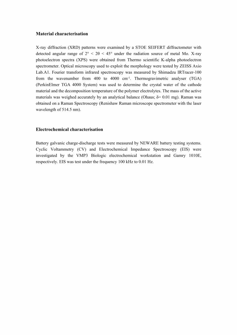
Material characterisation
X-ray diffraction (XRD) patterns were examined by a STOE SEIFERT diffractometer with detected angular range of 2° < 2θ < 45° under the radiation source of metal Mo. X-ray photoelectron spectra (XPS) were obtained from Thermo scientific K-alpha photoelectron spectrometer. Optical microscopy used to exploit the morphology were tested by ZEISS Axio Lab.A1. Fourier transform infrared spectroscopy was measured by Shimadzu IRTracer-100 from the wavenumber from 400 to 4000 cm-1. Thermogravimetric analyser (TGA) (PerkinElmer TGA 4000 System) was used to determine the crystal water of the cathode material and the decomposition temperature of the polymer electrolytes. The mass of the active materials was weighed accurately by an analytical balance (Ohaus; δ= 0.01 mg). Raman was obtained on a Raman Spectroscopy (Renishaw Raman microscope spectrometer with the laser wavelength of 514.5 nm).
Electrochemical characterisation
Battery galvanic charge-discharge tests were measured by NEWARE battery testing systems. Cyclic Voltammetry (CV) and Electrochemical Impedance Spectroscopy (EIS) were investigated by the VMP3 Biologic electrochemical workstation and Gamry 1010E, respectively. EIS was test under the frequency 100 kHz to 0.01 Hz.
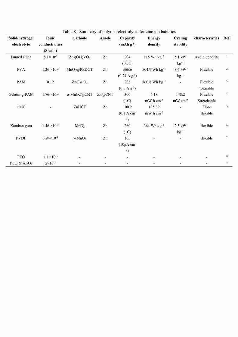
Table S1 Summary of polymer electrolytes for zinc ion batteriesSolid/hydrogel
electrolyteIonic
conductivities (S cm-1)
Cathode Anode Capacity(mAh g-1)
Energy density
Cycling stability
characteristics Ref.
Fumed silica 8.1×10⁻³ Zn2(OH)VO4 Zn 204(0.5C)
115 Wh kg−1 5.1 kW kg−1
Avoid dendrite 1
PVA 1.26 ×10⁻² MnO2@PEDOT Zn 366.6(0.74 A g-1)
504.9 Wh kg−1 8.6 kW kg−1
Flexible 2
PAM 0.12 Zn/Co3O4 Zn 205(0.5 A g-1)
360.8 Wh kg−1 - Flexiblewearable
3
Gelatin-g-PAM 1.76 ×10⁻² α-MnO2@CNT Zn@CNT 306(1C)
6.18mW h cm-2
148.2mW cm-2
FlexibleStretchable
4
CMC - ZnHCF Zn 100.2(0.1 A cm-
1)
195.39mW h cm-2
- Fibreflexible
5
Xanthan gum 1.46 ×10⁻² MnO2 Zn 260(1C)
364 Wh kg−1 2.5 kW kg−1
flexible 6
PVDF 3.94×10⁻³ γ-MnO2 Zn 105(10μA cm-
2)
- - flexible 7
PEO 1.1 ×10⁻⁵ - - - - - - 8
PEO & Al2O3 2×10⁻⁵ - - - - - - 8

Material characterisations
Figure S1. DSC check for the polymer electrolyte
Figure S2. Schematic diagram of polymerisation mechanism

Figure S3. (a) SEM image of the polymer electrolyte, (b) EDX mapping
a
b

Figure S4. EDX elemental ratio

-3 -2 -1 0 1 2 3
-0.08
0.00
0.08
0.16
0.24
Cur
rent
(mA)
Potential (V v.s. Zn/Zn2+)
1st cycle 2nd cycle
Figure S5. CV curve for Zn/EBSPE/Zn
Figure S6. Zinc deposition on the electrodes

Figure S7. Vacuum assisted resin transfer moulding
The polymer electrolyte in the liquid state formed a film on each component by laminating in a certain order. Then the entire structure was vacuum sealed and placed in an autoclave for the polymerisation. PEGDGE is a biodegradable epoxy resin, which has good surface crosslinking ability it strengthens the device from the mold from peeling. Therefore, peel ply, breather and releasing films which are normally used in carbon fibre composite manufacturing process were placed on the top of the laminates. Peel plies are used to easily peel off the device after the polymer polymerisation and leave a smooth surface; breathers are used to absorb extra liquid resin during curing and enable air bubble escape when vacuum is applied and the formed films exhibit no release characteristics and are typically placed directly with the laminate to avoiding the bonding to the mould.

Figure S8. XPS spectrums for the EBSPE

Table S2 Summary of ionic conductivities for different amount of PC
Figure S9 (a) Ionic conductivity with concentration of PC; (b) Ionic conductivity with concentration of ZnOTf
As shown in Figure S9a, there is a decrease of ionic conductivity when the content of PC is over an optimum value 45% (wt%) which is consistent with the outcome reported by Nithya. Regarding the concentration of ZnOTf, concentration of ZnOTf decreases as the increasing of PC content, however the ionic conductivities increase as the reduction of ZnOTf concentration. Hence, there is a slight influence of the ZnOTf concentration to the ionic conductivity when PC is 45% (wt%) in the polymer electrolyte. While once the PC concentration is greater than 50% in the polymer, the low content ratio of ZnOTf in the complexes results the decrease in the ionic conductivity.
No. PEGDGE (g) PC (g) TETA (g) ZnOf (g) Rb (Ω) σ (S cm-1)
1 2.00 0.00 0.15 0.20 2662.13×10-4
2 2.00 1.00 0.15 0.20 193 2.93×10⁻⁴
3 2.00 2.00 0.15 0.20 150 3.77×10⁻⁴
4 2.00 3.00 0.15 0.2 205 2.88×10⁻⁴

Figure S10. Raman spectra for solid polymer electrolyte (ABSPE) in comparison of pure PEGDGE resin
0 200 400 600
40
60
80
100
Mas
s (%
)
Temperature (C)
Figure S11. TGA for alginate hydrogel electrolyte
PEGDGEABSPE
1500 1350 1200 1050 9000.2
0.4
0.6
Nor
mal
ised
inte
nsity
(a.u
.)
Raman shift (cm-1)
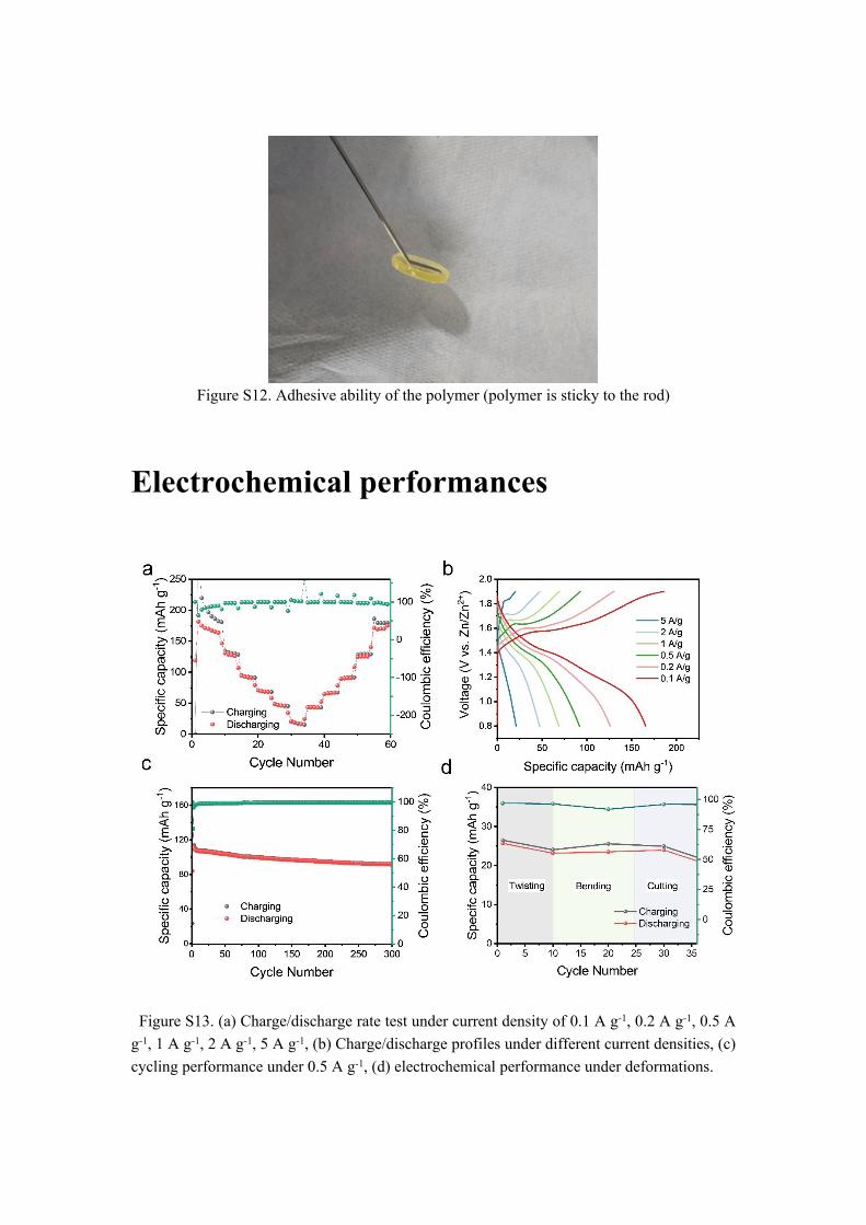
Figure S12. Adhesive ability of the polymer (polymer is sticky to the rod)
Electrochemical performances
Figure S13. (a) Charge/discharge rate test under current density of 0.1 A g-1, 0.2 A g-1, 0.5 A g-1, 1 A g-1, 2 A g-1, 5 A g-1, (b) Charge/discharge profiles under different current densities, (c) cycling performance under 0.5 A g-1, (d) electrochemical performance under deformations.

Figure S14. (a) SEM image of pristine Zn anode before cycling, (b) SEM image of Zn anode after the cycling test.

Reference1 D. Chao, C. (Rose) Zhu, M. Song, P. Liang, X. Zhang, N. H. Tiep, H. Zhao, J. Wang,
R. Wang, H. Zhang and H. J. Fan, Adv. Mater., 2018, 30, 1–7.2 Y. Zeng, X. Zhang, Y. Meng, M. Yu, J. Yi, Y. Wu, X. Lu and Y. Tong, Adv. Mater.,
2017, 29, 1–7.3 L. Ma, S. Chen, H. Li, Z. Ruan, Z. Tang, Z. Liu, Z. Wang, Y. Huang, Z. Pei, J. A.
Zapien and C. Zhi, Energy Environ. Sci., 2018, 11, 2521–2530.4 H. Li, C. Han, Y. Huang, Y. Huang, M. Zhu, Z. Pei, Q. Xue, Z. Wang, Z. Liu, Z. Tang,
Y. Wang, F. Kang, B. Li and C. Zhi, Energy Environ. Sci., 2018, 11, 941–951.5 Q. Zhang, C. Li, Q. Li, Z. Pan, J. Sun, Z. Zhou, B. He, P. Man, L. Xie, L. Kang, X.
Wang, J. Yang, T. Zhang, P. P. Shum, Q. Li, Y. Yao and L. Wei, Nano Lett., 2019, 19, 4035–4042.
6 S. Zhang, N. Yu, S. Zeng, S. Zhou, M. Chen, J. Di and Q. Li, J. Mater. Chem. A, 2018, 6, 12237–12243.
7 G. G. Kumar and S. Sampath, Solid State Ionics, 2003, 160, 289–300.8 I. Pucić and A. Turković, Solid State Ionics, 2005, 176, 1797–1800.