Embed Size (px)
Citation preview
Appl. Math. Inf. Sci. 7, No. 1L, 339-345 (2013) 339
Applied Mathematics & Information SciencesAn International Journal
c⃝ 2013 NSPNatural Sciences Publishing Cor.
Experimental Research on the Instability Characteristicsof Double-layer Rock Plates Based on MTS-AE System
Shuren Wang1,3, Paul Hagan2 and Yan Cheng2
1School of Civil Engineering and Mechanics, Yanshan University, Qinhuangdao, 066004 P. R. China2School of Mining Engineering, University of New South Wales, Sydney, 2052 Australia3Key Laboratory of Mechanical Reliability for Heavy Equipments and Large Structures, Qinhuangdao, 066004 P. R. China
Received: 19 Jul. 2012, Revised: 19 Oct. 2012, Accepted: 30 Oct. 2012Published online: 1 Feb. 2013
Abstract: The deformation and failure process of four classes of double-layer rock plates were researched experimentally with the newloading device under concentrated load based on MTS-AE system. The force-displacement curves and the force-time-acoustic emissionevent rate curves were obtained through the experiments. The results showed that there were three failure modes of beam fracture, archdestruction and plate fracture damage in the upper plate of the double-layer rock plates; all the lower plates of the four classes of rockplates produced the beam fracture damage. There were four distinct mechanical response stages in the force-displacement curves; threetypes of mechanical behavior of the double-layer rock plates arose after the second load peak, which were post-peak yielding, post-peakhardening and post-peak softening; the bearing capacity of the double-layer rock plates is usually greater than that of the single-layerrock plate. It showed that the acoustic emission events were not only in the phase before the peak value, but also in the post-peak phase.
Keywords: Rock plate, acoustic emission, laboratory test, mined-out areas.
1. Introduction
In the past three decades, numerous shallow mined-outareas had been left due to disordered mining by privatecoal mines in China. With the decrease of available landresources, a number of industrial and civil buildings, andmany structures such as expressways, bridges and tunnelshad to cross the mined-out areas. The stress of overlyingstrata in shallow mined-out areas was redistributed afterthe coal being mined, and then ground subsidence anddestruction of these buildings appeared, which seriouslyaffected the building plan, construction and operation ofthe structures built above the mined-out areas [1].
The layered sedimentary strata structure was thecommon structure type of the rock roof in the coalmined-out areas. Considering the effect of the beddingstructure, the characteristics of transverse isotropy and theinteraction between layers, the deformation feature,failure mode and fracture mechanism of the layered roofwere more complicated. Thus, it is the difficult problemthat needs to be urgently solved to study on the roofdeformation and failure process and catastrophemechanism in engineering practice.
At present, on one hand, most scholars at home andabroad usually regarded the roof of mined-out areas as therock beam to do mechanical analysis and the relevanttests [2-6]. The processing method simplified the analyticprocess but it has apparent limitations, which can notreflect the spatial effect and the anisotropic of the roof, sothe reliability of the results caused unavoidably doubt. Onthe other hand, most analysis and design are based on thethin plate theory, while the practical ratio of length tothickness of the roof could not meet the requirement ofthe thin plate theory [7-9]. In practical miningengineering, the major deformation and failure of the roofof the mined-out areas mostly performed rock-plate types,further more it usually expressed the layered rock plates.Therefore, it is necessary to develop and design a newloading device which could simulate the process of thedeformation of thin plates, thick plates or thin-thickcombined plates, which is the key to study on thedeformation and failure process and catastrophemechanism of the roof of the mined-out areas [10-15].
∗ Corresponding author e-mail: w−[email protected]⃝ 2013 NSP
Natural Sciences Publishing Cor.
340 Shuren Wang et al. : Experimental Research on the Instability...
2. Experimental Design
2.1. Sandstone samples and test programs
The rock samples used in the test were Hawkesburysandstone, which obtained from Gosford Quarry inSydney, Australia. The quartz sandstones whichcontained a small quantity of feldspars, siderite, and clayminerals were formed in marine sedimentary basin of themid-Triassic, and located on the top of coal-bearingstrata. The surface of specimen exhibited local red ratherthan usual white because of the content and distributionof iron oxide.
For the single-layer roof of the mined-out areas, itcould be classified into two categories according to thethickness: the thin plate and the thick plate. And the roofwas always made up of various combinations of the thinplates and the thick plates. Thus, according to thedefinition of the thin plate and the thick plate in elasticmechanics, the specimen size of the thick plate wasdeigned to 190 mm ×75 mm × 24 mm (length, width,and thickness) and that of the thin plate was deigned to190 mm × 75 mm × 14 mm (length, width, andthickness). According to the sizes above mentioned, thespecimens was obtained by cutting the same sandstone inthe laboratory of School of Mining Engineering,University of New South Wales. The physical-mechanicalparameters of rock plates were shown in Table 1.
Under the concentrated load, the double-layer rockplates contacted closely, and performed the bendingdeformation together; the frictional resistance caused byslide between these two plates could reflect themechanical effects of the interaction to some extent.
In the test, these double-layer rock plates wereclassified into four categories: upper thin plate and lowerthick plate, upper thick plate and lower thin plate,double-layer thin plates and double-layer thick plates.Every sort of rock plates were produced for three sets andthe comparative tests were done under the sameconditions.
Table 1 Physical-mechanical parameters of rock plates.
NameD
(kg·m−3)E
(GPa) v C(MPa)
F( o)
T(MPa)
Cs(MPa)
Sandstone 2650 2.7 0.2 2.8 45 0.95 13.5
Notes
D-Density; E-Elastic modulus; v-Poisson ratio;C-Cohesion; F-Friction angle; T-Tensile strength;Cs-Compression strength.
2.2. Loading devices and loading modes
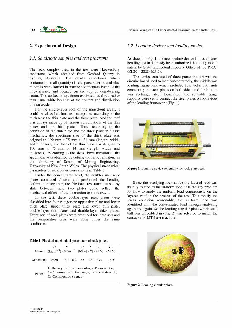
As shown in Fig. 1, the new loading device for rock platesbending test had already been authorized the utility modelpatent by State Intellectual Property Office of the P.R.C.(ZL201120284625.7).
The device consisted of three parts: the top was thecircular board used to load concentratedly, the middle wasloading framework which included four bolts with nutsconnecting the steel plates on both sides, and the bottomwas rectangle steel foundation, the rotatable hingesupports were set to connect the steel plates on both sidesof the loading framework (Fig. 1).
Figure 1 Loading device schematic for rock plates test.
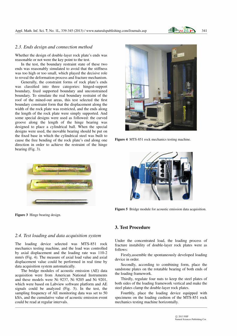
Since the overlying rock above the layered roof wasusually treated as the uniform load, it is the key problemfor how to apply the uniform load continuously on thelayered roof in the process of the test. To simplify thestress condition reasonably, the uniform load wasidentified with the concentrated load through analyzingagain and again. So the loading circular plate which steelball was embedded in (Fig. 2) was selected to match thecontactor of MTS test machine.
Figure 2 Loading circular plate.
c⃝ 2013 NSPNatural Sciences Publishing Cor.
Appl. Math. Inf. Sci. 7, No. 1L, 339-345 (2013) / www.naturalspublishing.com/Journals.asp 341
2.3. Ends design and connection method
Whether the design of double-layer rock plate’s ends wasreasonable or not were the key point to the test.
In the test, the boundary restraint state of these twoends was reasonably simulated to avoid that the stiffnesswas too high or too small, which played the decisive roleto reveal the deformation process and fracture mechanism.
Generally, the constraint forms of rock plate’s endswas classified into three categories: hinged-supportboundary, fixed supported boundary and unconstrainedboundary. To simulate the real boundary restraint of theroof of the mined-out areas, this test selected the firstboundary constraint form that the displacement along thewidth of the rock plate was restricted, and the ends alongthe length of the rock plate were simply supported. Andsome special designs were used as followed: the curvedgroove along the length of the hinge bearing wasdesigned to place a cylindrical ball. When the specialdesigns were used, the movable bearing should be put onthe fixed base in which the cylindrical steel was built tocause the free bending of the rock plate’s end along onedirection in order to achieve the restraint of the hingebearing (Fig. 3).
Figure 3 Hinge bearing design.
2.4. Test loading and data acquisition system
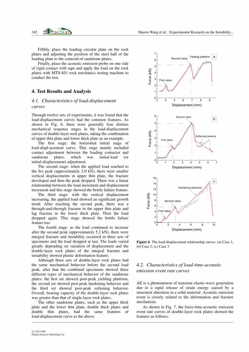
The loading device selected was MTS-851 rockmechanics testing machine, and the load was controlledby axial displacement and the loading rate was 110-2mm/s (Fig. 4). The measure of axial load value and axialdisplacement value could be performed in real time bydata acquisition system automatically.
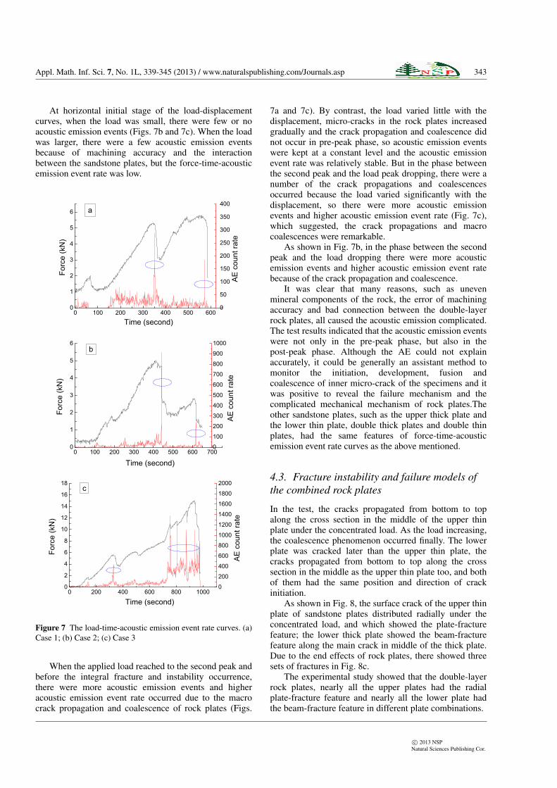
The bridge modules of acoustic emission (AE) dataacquisition were from American National Instrumentsand these models were Ni 9237, Ni 9205 and Ni 9201,which were based on Labview software platform and AEsignals could be analyzed (Fig. 5). In the test, thesampling frequency of AE monitoring data was set to 50kS/s, and the cumulative value of acoustic emission eventcould be read at regular intervals.
Figure 4 MTS-851 rock mechanics testing machine.
Figure 5 Bridge module for acoustic emission data acquisition.
3. Test Procedure
Under the concentrated load, the loading process offracture instability of double-layer rock plates were asfollows:
Firstly,assemble the spontaneously developed loadingdevice in order.
Secondly, according to combining form, place thesandstone plates on the rotatable bearing of both ends ofthe loading framework.
Thirdly, regulate four nuts to keep the steel plates ofboth sides of the loading framework vertical and make thesteel plates clamp the double-layer rock plates.
Fourthly, place the loading device equipped withspecimens on the loading cushion of the MTS-851 rockmechanics testing machine horizontally.
c⃝ 2013 NSPNatural Sciences Publishing Cor.
342 Shuren Wang et al. : Experimental Research on the Instability...
Fifthly, place the loading circular plate on the rockplates and adjusting the position of the steel ball of theloading plate to the centroid of sandstone plates.
Finally, place the acoustic emission probe on one sideof rigid contact with tape and apply the load on the rockplates with MTS-851 rock mechanics testing machine toconduct the test.
4. Test Results and Analysis
4.1. Characteristics of load-displacementcurves
Through twelve sets of experiments, it was found that theload-displacement curves had the common features. Asshown in Fig. 6, there were generally four distinctmechanical response stages in the load-displacementcurves of double-layer rock plates, taking the combinationof upper thin plate and lower thick plate as an example.
The first stage: the horizontal initial stage ofload-displ-acement curve. This stage mainly includedcontact adjustment between the loading contactor andsandstone plates, which was initial-load (orinitial-displacement) adjustment.
The second stage: when the applied load reached tothe firs peak (approximately 2.0 kN), there were smallervertical displacements in upper thin plate, the fracturedeveloped and then the peak dropped. There was a linearrelationship between the load increment and displacementincrement and this stage showed the brittle failure feature.
The third stage: with the vertical displacementincreasing, the applied load showed an significant growthtrend. After reaching the second peak, there was athrough-and-through fracture in the upper thin plate andlag fracture in the lower thick plate. Then the loaddropped again. This stage showed the brittle failurefeature too.
The fourth stage: as the load continued to increaseafter the second peak (approximately 5.2 kN), there wereintegral fracture and instability occurred in three sets ofspecimens and the load dropped at last. The loads variedgreatly depending on variation of displacement and thedouble-layer rock plates of the integral fracture andinstability showed plastic deformation feature.
Although three sets of double-layer rock plates hadthe same mechanical behavior before the second loadpeak, after that the combined specimens showed threedifferent types of mechanical behavior of the sandstoneplates: the first set showed post-peak yielding platform,the second set showed post-peak hardening behavior andthe third set showed post-peak softening behavior.Overall, bearing capacity of the double-layer rock plateswas greater than that of single-layer rock plates.
The other sandstone plates, such as the upper thickplate and the lower thin plate, double thick plates anddouble thin plates, had the same features ofload-displacement curve as the above.
3 4 5 6 7 8 90
1
2
3
4
5
6
7 a Yielding platformSecond value
Forc
e (k
N)
Displacement (mm)
First value
0 1 2 3 4 5 6 70
1
2
3
4
5
6 b
Softening behavior
Second value
First value
Forc
e (k
N)
Displacement (mm)
0 2 4 6 8 100
2
4
6
8
10
12
14
16 c
Hardening behavior
Second value
First value
Forc
e (k
N)
Displacement (mm)
Figure 6 The load-displacement relationship curves. (a) Case 1;(b) Case 2; (c) Case 3
4.2. Characteristics of load-time-acousticemission event rate curves
AE is a phenomenon of transient elastic-wave generationdue to a rapid release of strain energy caused by astructural alteration in a solid material. Acoustic emissionevent is closely related to the deformation and fracturemechanism.
As shown in Fig. 7, the force-time-acoustic emissionevent rate curves of double-layer rock plates showed thefeatures as follows:
c⃝ 2013 NSPNatural Sciences Publishing Cor.
Appl. Math. Inf. Sci. 7, No. 1L, 339-345 (2013) / www.naturalspublishing.com/Journals.asp 343
At horizontal initial stage of the load-displacementcurves, when the load was small, there were few or noacoustic emission events (Figs. 7b and 7c). When the loadwas larger, there were a few acoustic emission eventsbecause of machining accuracy and the interactionbetween the sandstone plates, but the force-time-acousticemission event rate was low.
0 100 200 300 400 500 6000
1
2
3
4
5
6
0
50
100
150
200
250
300
350
400 a
Forc
e (k
N)
Time (second)
AE
cou
nt ra
te
0 100 200 300 400 500 600 7000
1
2
3
4
5
6
0
100
200
300
400
500
600
700
800
900
1000
Forc
e (k
N)
b
AE
cou
nt ra
te
Time (second)
0
200
400
600
800
1000
1200
1400
1600
1800
2000
0 200 400 600 800 10000
2
4
6
8
10
12
14
16
18
AE
cou
nt ra
te
c
Forc
e (k
N)
Time (second)
Figure 7 The load-time-acoustic emission event rate curves. (a)Case 1; (b) Case 2; (c) Case 3
When the applied load reached to the second peak andbefore the integral fracture and instability occurrence,there were more acoustic emission events and higheracoustic emission event rate occurred due to the macrocrack propagation and coalescence of rock plates (Figs.
7a and 7c). By contrast, the load varied little with thedisplacement, micro-cracks in the rock plates increasedgradually and the crack propagation and coalescence didnot occur in pre-peak phase, so acoustic emission eventswere kept at a constant level and the acoustic emissionevent rate was relatively stable. But in the phase betweenthe second peak and the load peak dropping, there were anumber of the crack propagations and coalescencesoccurred because the load varied significantly with thedisplacement, so there were more acoustic emissionevents and higher acoustic emission event rate (Fig. 7c),which suggested, the crack propagations and macrocoalescences were remarkable.
As shown in Fig. 7b, in the phase between the secondpeak and the load dropping there were more acousticemission events and higher acoustic emission event ratebecause of the crack propagation and coalescence.
It was clear that many reasons, such as unevenmineral components of the rock, the error of machiningaccuracy and bad connection between the double-layerrock plates, all caused the acoustic emission complicated.The test results indicated that the acoustic emission eventswere not only in the pre-peak phase, but also in thepost-peak phase. Although the AE could not explainaccurately, it could be generally an assistant method tomonitor the initiation, development, fusion andcoalescence of inner micro-crack of the specimens and itwas positive to reveal the failure mechanism and thecomplicated mechanical mechanism of rock plates.Theother sandstone plates, such as the upper thick plate andthe lower thin plate, double thick plates and double thinplates, had the same features of force-time-acousticemission event rate curves as the above mentioned.
4.3. Fracture instability and failure models ofthe combined rock plates
In the test, the cracks propagated from bottom to topalong the cross section in the middle of the upper thinplate under the concentrated load. As the load increasing,the coalescence phenomenon occurred finally. The lowerplate was cracked later than the upper thin plate, thecracks propagated from bottom to top along the crosssection in the middle as the upper thin plate too, and bothof them had the same position and direction of crackinitiation.
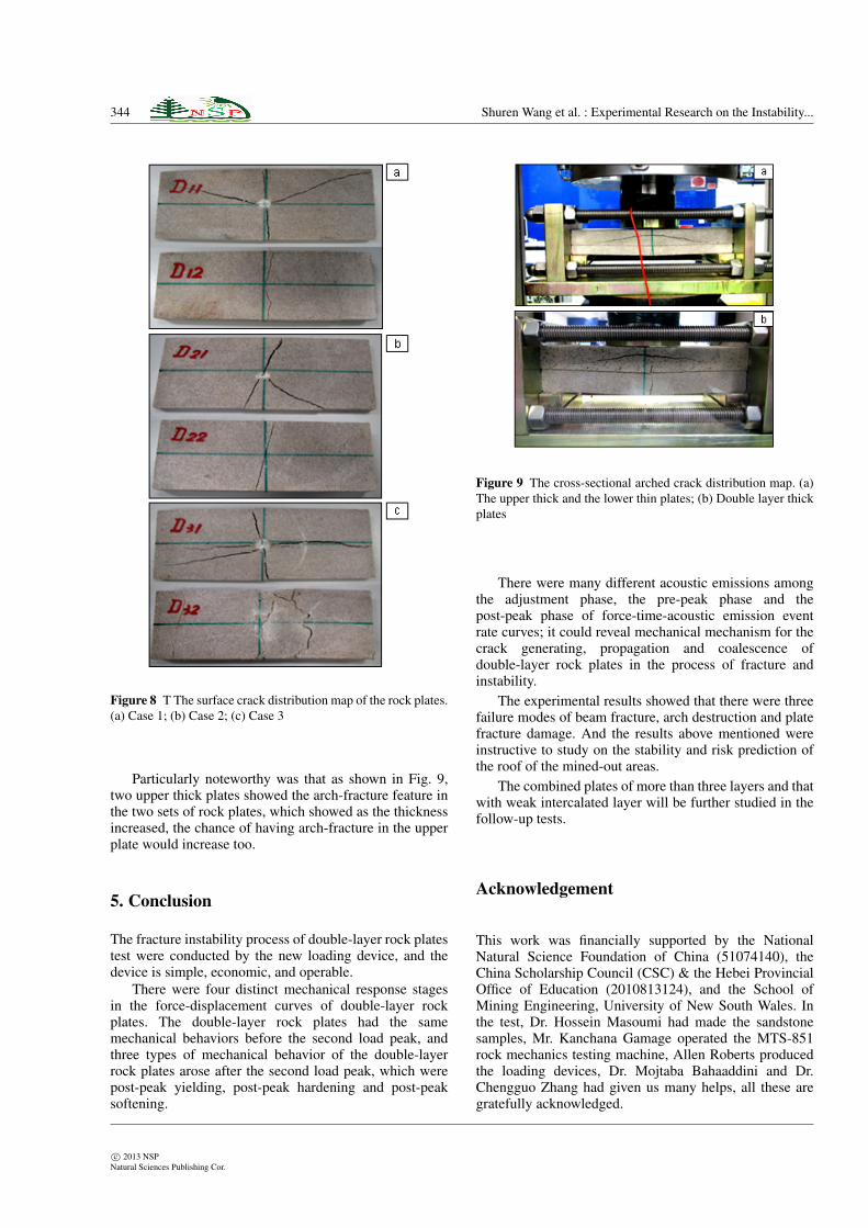
As shown in Fig. 8, the surface crack of the upper thinplate of sandstone plates distributed radially under theconcentrated load, and which showed the plate-fracturefeature; the lower thick plate showed the beam-fracturefeature along the main crack in middle of the thick plate.Due to the end effects of rock plates, there showed threesets of fractures in Fig. 8c.
The experimental study showed that the double-layerrock plates, nearly all the upper plates had the radialplate-fracture feature and nearly all the lower plate hadthe beam-fracture feature in different plate combinations.
c⃝ 2013 NSPNatural Sciences Publishing Cor.
344 Shuren Wang et al. : Experimental Research on the Instability...
Figure 8 T The surface crack distribution map of the rock plates.(a) Case 1; (b) Case 2; (c) Case 3
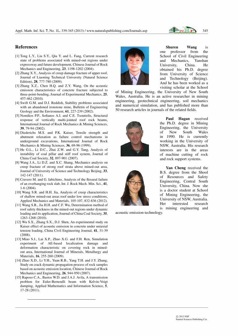
Particularly noteworthy was that as shown in Fig. 9,two upper thick plates showed the arch-fracture feature inthe two sets of rock plates, which showed as the thicknessincreased, the chance of having arch-fracture in the upperplate would increase too.
5. Conclusion
The fracture instability process of double-layer rock platestest were conducted by the new loading device, and thedevice is simple, economic, and operable.
There were four distinct mechanical response stagesin the force-displacement curves of double-layer rockplates. The double-layer rock plates had the samemechanical behaviors before the second load peak, andthree types of mechanical behavior of the double-layerrock plates arose after the second load peak, which werepost-peak yielding, post-peak hardening and post-peaksoftening.
Figure 9 The cross-sectional arched crack distribution map. (a)The upper thick and the lower thin plates; (b) Double layer thickplates
There were many different acoustic emissions amongthe adjustment phase, the pre-peak phase and thepost-peak phase of force-time-acoustic emission eventrate curves; it could reveal mechanical mechanism for thecrack generating, propagation and coalescence ofdouble-layer rock plates in the process of fracture andinstability.
The experimental results showed that there were threefailure modes of beam fracture, arch destruction and platefracture damage. And the results above mentioned wereinstructive to study on the stability and risk prediction ofthe roof of the mined-out areas.
The combined plates of more than three layers and thatwith weak intercalated layer will be further studied in thefollow-up tests.
Acknowledgement
This work was financially supported by the NationalNatural Science Foundation of China (51074140), theChina Scholarship Council (CSC) & the Hebei ProvincialOffice of Education (2010813124), and the School ofMining Engineering, University of New South Wales. Inthe test, Dr. Hossein Masoumi had made the sandstonesamples, Mr. Kanchana Gamage operated the MTS-851rock mechanics testing machine, Allen Roberts producedthe loading devices, Dr. Mojtaba Bahaaddini and Dr.Chengguo Zhang had given us many helps, all these aregratefully acknowledged.
c⃝ 2013 NSPNatural Sciences Publishing Cor.
Appl. Math. Inf. Sci. 7, No. 1L, 339-345 (2013) / www.naturalspublishing.com/Journals.asp 345
References
[1] Tong L.Y., Liu S.Y., Qiu Y. and L. Fang, Current researchstate of problems associated with mined-out regions underexpressway and future development, Chinese Journal of RockMechanics and Engineering, 23, 1198-1202 (2004).
[2] Zhang X.Y., Analysis of creep damage fracture of upper roof,Journal of Liaoning Technical University (Natural ScienceEdition), 28, 777-780 (2009).
[3] Zhang X.Z., Chen H.Q. and Z.Y. Wang, On the acousticemission characteristics of concrete fracture subjected tothree-point-bending, Journal of Experimental Mechanics, 25,457-462 (2010).
[4] Swift G.M. and D.J. Reddish, Stability problems associatedwith an abandoned ironstone mine, Bulletin of EngineeringGeology and the Environment, 61, 227-239 (2002).
[5] Nomikos P.P., Sofianos A.I. and C.E. Tsoutrelis, Structuralresponse of vertically multi-jointed roof rock beams,International Journal of Rock Mechanics & Mining Sciences,39, 79-94 (2002).
[6] Diederichs M.S. and P.K. Kaiser, Tensile strength andabutment relaxation as failure control mechanisms inunderground excavations, International Journal of RockMechanics & Mining Sciences, 36, 69-96 (1999).
[7] He G.L., Li D.C., Zhai Z.W. and G.Y. Tang, Analysis ofinstability of coal pillar and stiff roof system, Journal ofChina Coal Society, 32, 897-901 (2007).
[8] Wang J.A., Li D.Z. and X.C. Shang, Mechanics analysis oncreep fracture of strong roof strata above mined-out area,Journal of University of Science and Technology Beijing, 33,142-147 (2011).
[9] Cravero M. and G. Iabichino, Analysis of the flexural failureof an overhanging rock slab, Int. J. Rock Mech. Min. Sci., 41,1-6 (2004).
[10] Wang S.R. and H.H. Jia, Analysis of creep characteristicsof shallow mined-out areas roof under low stress conditions,Applied Mechanics and Materials, 105-107, 832-836 (2012).
[11] Wang S.R., Jia H.H. and C.F. Wu, Determination method ofroof safety thickness in the mined-out regions under dynamicloading and its application, Journal of China Coal Society, 35,1263-1268 (2010).
[12] Wu S.X., Zhang S.X., D.J. Shen, An experimental study onKaiser effect of acoustic emission in concrete under uniaxialtension loading, China Civil Engineering Journal, 41, 31-39(2008).
[13] Miao S.J., Lai X.P., Zhao X.G. and F.H. Ren, Simulationexperiment of AE-based localization damage anddeformation characteristic on covering rock in mined-out area, International Journal of Minerals, Metallurgy andMaterials, 16, 255-260 (2009).
[14] Zhao X.D., Li Y.H., Yuan R.B., Yang T.H. and J.Y. Zhang,Study on crack dynamic propagation process of rock samplesbased on acoustic emission location, Chinese Journal of RockMechanics and Engineering, 26, 944-950 (2007).
[15] Raposo C.A., Bastos W.D. and J.A.J. Avila, A transmissionproblem for Euler-Bernoulli beam with Kelvin-Voigtdamping, Applied Mathematics and Information Science, 5,17-28 (2011).
Shuren Wang isone professor from theSchool of Civil Engineeringand Mechanics, YanshanUniversity, China. Heobtained his Ph.D. degreefrom University of Scienceand Technology (Beijing).And he has been worked as avisiting scholar at the School
of Mining Engineering, the University of New SouthWales, Australia. He is an active researcher in miningengineering, geotechnical engineering, soil mechanicsand numerical simulation, and has published more than50 research articles in journals of the related fields.
Paul Hagan receivedthe Ph.D. degree in MiningEngineering, the Universityof New South Walesin 1990. He is currentlyworking in the University ofNSW, Australia. His researchinterests are in the areasof machine cutting of rockand rock support systems.
Yan Cheng received theB.S. degree from the Shoolof Resources and SafetyEngineering, Central SouthUniversity, China. Now sheis a doctor student at Schoolof Mining Engineering, theUniversity of NSW, Australia.Her interested researchis mining engineering and
acoustic emission technology.
c⃝ 2013 NSPNatural Sciences Publishing Cor.