Embed Size (px)
Citation preview

5th International & 26th All India Manufacturing Technology, Design and Research Conference (AIMTDR 2014) December 12th–14th, 2014,
IIT Guwahati, Assam, India
836-1
EXPERIMENTAL INVESTIGATIONS ON PLASMA ARC WELLDING
OF LEAN SUPERMARTENSITIC STAINLESS STEEL
1Birendra Kumar Barik, 1*P. Sathiya and 2S.Aravindan
1Department of Production Engineering, National Institute of Technology Tiruchirappalli-620015, Tamilnadu, India. 2Department of Mechanical Engineering,
Indian Institute of Technology Delhi, New Delhi-110016, India *Corresponding author: psathiya @ nitt.edu; Tel.:+91 431 2503510; Fax: +91 431
2500133
Abstract Nowadays the lean super martensitic stainless steel (LSMSS) becomes an economical alternative to the
traditional carbon and/or austenitic-ferritic (duplex) stainless steel for the construction of pipelines in transport
of gas and corrosive oils. Lean super martensitic stainless steel exhibits higher toughness, corrosion resistance
and weldability properties when compared to conventional martensitic stainless steel. The main purpose of this
study is to investigate the mechanical and metallurgical properties of welds made by the keyhole mode of
plasma arc butt welded joints. The macrostructure and microstructure were evaluated through optical
microscope. The mechanical properties such as tensile and impact tests were carried out at room temperature
and their fractured surfaces were also analysed through scanning electron microscope (SEM). The corrosion
resistance of the weld is determined by electro chemical analysis using Tafel plot and the same is correlated
with their microstructures.
Keywords:Lean super martensitic stainless steel, Mechanical and Metallurgical characterization, Corrosion resistance.
1 Introduction
The super martensitic stainless steels (SMSS) are
also known as weldable 12%Cr steels, weldable
13%Cr steels, low carbon martensitic stainless
steels and soft martensitic stainless steels. These
steels have carbon contents of the order of 0.01%
and Nickel addition in the range 1-6% to stabilize
the martensitic microstructures and chromium is
typically between 10-13%. Due to different
alloying and processing requirements, compared
with 22%Cr duplex stainless steels, these super
martensitic steels are substantially cheaper than the
competing duplex grades for pipeline and flow line
applications (Goldschmitz et al., 2004, Lauro et al.,
2003, Gooch et al.,1999, Carrouge 2002, Lippold et
al.,2005, van-der-Winden et al.,2002). Two classes
of SMSS may be identified: ′high′ and 'lean' grades.
Lean super martensitic stainless steel (LSMSS)
typically contain approximately 12%Cr, <4%Ni, no
molybdenum and about 0.01%C. The
microstructure of such steels is predominantly
tempered martensite with some austenite but delta
ferrite and untempered martensite may form in
weld HAZs (Woollin et al.,2002, Marshall et
al.,2001, Gooch et al.,1999, Folkhard 1984)
This alloy was developed as a practical and
economical alternative to carbon steel and
corrosion inhibitors, replacing some of the duplex
stainless steels used in offshore pipelines (Woollin
et al., 2006). Crack free welds with good HAZ
toughness can be processed without pre and post
weld heat treatment (Dufrane et al., 1999,
Enerhaug et al., 1999). In supermartensitic alloys,
the Cr and Ni ratio equivalents promote the
formation of a martensite and retained austenite
microstructure. The retained austenite phase may
represent a volume of only a few percent
(characteristic of low alloy) up to 40%
(characteristic of high alloy), but it is nevertheless
very difficult to identify because it is dispersed in
the martensitic structure (Toussaint et al., 2002).
Super martensitic stainless steels combine good
mechanical properties, weldability, toughness and
corrosion resistance to CO2 and H2S. Corrosion in
supermartensitic welds is clearly dependent on the
metallurgical phases present, like retained austenite
and δ ferrite. It was demonstrated that pitting

EXPERIMENTAL INVESTIGATIONS ON PLASMA ARC WELLDING OF LEAN SUPERMARTENSITIC STAINLESS STEEL
836-2
potential becomes nobler with the retained
austenite content. Moreover, δ-ferrite increases
corrosion susceptibility because it promotes the
precipitation of chromium nitrides or carbides and
the formation of chromium depleted zones (Bilmes
et al., 2006, Aquino et al.,2008). Also, micro
segregation, welding thermal cycles and inclusions
are important factors in the resulting microstructure
of a weld and its corresponding corrosion
susceptibility.
The plasma arc welding (PAW) closely
resembles the tungsten-inert gas (TIG) welding
process in that it also uses a non-consumable
tungsten electrode and a shielding gas such as
Argon. The keyhole welding is generally obtained
by using a stiff and constricted arc. With increased
plasma gas flow rate and electrode setback, a hole
known as the “keyhole” is pierced through the
entire metal thickness at the leading edge of the
weld pool, where the forces of plasma column
displaces the molten metal(Wu et al., 2011, Wu et
al., 2013).
The keyhole is a positive indication of full
penetration, and it allows higher welding speeds to
be used in PAW. LSMSS have high strengths,
around 480MPa proof strength and above
consequently, high strength filler metals are
required to provide matching weld metal strength.
Matching 12/13%Cr consumables have been
developed in solid wire and metal cored wire forms
but have not been successfully used for industrial
applications. Therefore, keyhole mode of PAW is
great alternative to weld LSMSS without using the
filler material. The preferred welding processes to
date for LSMSS have been automatic pulsed gas
metal arc (PGMA) and gas tungsten arc welding
(GTAW) welding. There is no metallurgical reason
why other conventional arc welding processes such
as manual metal arc (MMA) and flux cored arc
welding (FCAW) may not be used for girth welds.
At present, there is little information regarding
welding of LSMSS using high energy density
welding processes such as plasma arc welding
(PAW), laser beam welding (LBM), ion beam
welding (IBM).
In the present work, 410S lean super
martensitic stainless steel plates were welded using
keyhole mode of PAW process and the welded
joints were evaluated by mechanical and
metallurgical and corrosion tests.
2 Methodology
The flow chart of methodology is presented below:
Figure 1 Flowchart of methodology
2.1 Material
AISI 410S plates of 6 mm thickness, hot
rolled shot blasted plate in solution annealed &
pickled condition were used as the base material.
The base material has the yield strength of 348
MPa and ultimate strength of 480 MPa. The
specimens were prepared in dimension of 100 x
150 x 6 mm3.The chemical composition of the base
material is presented in Table 1.
Table 1 Chemical composition of base material
2.2 Welding Trials
Through preliminary trials welding parameters
were identified. Initially bead on plate experiments
were carried out and suitable parameters and their
range were obtained. The identified parameters
such as welding current (I), welding speed (S),
plasma gas flow rate (FR), nozzle standoff distance
(d) were used to conduct the keyhole mode of
plasma arc welding (PAW) on the material in flat
position. Using bead on plate tests, the full
penetration was achieved as shown in the Table 2.
The plasma arc welding (Fronius Magic Wave 440)
set up was used for welding is shown in Fig.2.
Figure 2 Experimental set up for PAW
Elements C Cr Ni Mn Si P S
In % 0.028 11.9 0.21 0.40 0.41 0.03 0.005
Welding Trials
PAW LSMSS
LSMSS Keyhole Plasma arc weldment
Mechanical
Invastigation Metallurgical
Invastigation
Corrosion
Studies
Results &
Discussions
Conclusions

5th International & 26th All India Manufacturing Technology, Design and Research Conference (AIMTDR 2014) December 12
IIT Guwahati, Assam, India
Table 2 Parameters used for PAW p
S.
No.
d
mm
I
amp
S
mm/min
FR
l/min
1 4 140 375 1.5
2 4 160 375 1.5
3 4 160 250 2.5
4 4 170 125 2.5
5 5 160 375 1.5
6 5 160 250 1.5
7 5 160 125 2.5
8 5 170 125 2.5
9 6 170 125 2.5
10 6 170 375 1.5
11 6 160 375 2.5
12 6 160 250 1.5
13 6 160 375 1.5
14 6 160 250 2.5
but undercut
15 6 160 125 2.5
penetration
The cut blanks were machined with perpendicular
to each other than surface grounded to make air
tight gap between two joining plates. Just prior to
welding, plates were cleaned with fresh stainless
steel wire brush followed by acetone swabbing.
The welding process was performed under
as shielding gas and plasma gas. The photographic
views of the weld samples are presented in Figure
3. After welding, the weld surfaces were cleaned
with steel wire brush followed by acetone
swabbing. The weld was then subjected to liquid
penetrant test and radiographic tests.
confirmed that there is no micro cracks and
discontinuities.
Figure 3 Photographic view of weld sample
All India Manufacturing Technology, Design and Research Conference (AIMTDR 2014) December 12
Table 2 Parameters used for PAW process
Remarks
Not welded
Not welded
Not welded
Not welded
Not welded
Not welded
Partial
penetration
Not welded
Not welded
Not welded
Partial
penetration
Welded but
porosity
Partial
penetration
Full
penetration
but undercut
Full
penetration
without
defect
The cut blanks were machined with perpendicular
surface grounded to make air
es. Just prior to
were cleaned with fresh stainless
steel wire brush followed by acetone swabbing.
under Argon
as shielding gas and plasma gas. The photographic
views of the weld samples are presented in Figure
. After welding, the weld surfaces were cleaned
with steel wire brush followed by acetone
bjected to liquid
and radiographic tests. It is
no micro cracks and
Photographic view of weld sample
2.3 Mechanical Testing In order to evaluate the variation in the mechani
properties of the material tensile
temperature (RT), Charpy impact at RT and
and hardness tests were carried out.
specimens for all the mechanical testing were
prepared as per the guidelines of ASTM A370
standard. The fractured surfaces of tensile and
impact tested specimens were examined through
the scanning electron microscope (SEM).
2.4 Metallurgical Study
An optical microscope was used to identify the
microstructural changes in the base material, HAZ
and weld region. The specimens were prepared,
mechanically polished and etched with
reagent( 5 ml HCl + 1gm Picric acid + 100 ml
Ethanol) until the phases were identified.
2.5 Corrosion test details
The electrochemical measurements were perfo
using a conventional three electrode cell. It
contained a platinum grid, a saturated calomel
reference electrode (SCE) and a plate of the lean
supermartensitic stainless steel, of 1 cm² cross
sectional area, used as working elect
corrosive medium was prepared from di
water by adding 3.5% NaCl. Polarisation curves
were plotted under potentiodynamic
using a core running 1287 electrochemical interface
(ACM-Grill). The cathodic and anodic branches
were plotted in corrosion potential (Ecorr) verses
corrosion current (Icorr). The SEM images of base
and welded corroded surface were studied to
analyse the corrosion properties.
3 Results and Discussion
3.1 Macrostructure Examination
The weld bead was cross
correspondence of its normal symmetrical p
shown in the Figure 4, in order to investig
bead characteristics. Cross-section was
observation with optical microscop
geometry was studied by measurin
parameters, bead width, bead height and
penetration using image J software.
Figure 4 Weld bead profile
From Figure 4, it is observed that
achieved full penetration without any defects
All India Manufacturing Technology, Design and Research Conference (AIMTDR 2014) December 12th–14th, 2014,
836-3
In order to evaluate the variation in the mechanical
ensile test at room
temperature (RT), Charpy impact at RT and -1960C
carried out. Standard
specimens for all the mechanical testing were
prepared as per the guidelines of ASTM A370
surfaces of tensile and
impact tested specimens were examined through
nning electron microscope (SEM).
An optical microscope was used to identify the
microstructural changes in the base material, HAZ
ecimens were prepared,
mechanically polished and etched with Villella’s
Cl + 1gm Picric acid + 100 ml
thanol) until the phases were identified.
The electrochemical measurements were performed
electrode cell. It
a saturated calomel
reference electrode (SCE) and a plate of the lean
supermartensitic stainless steel, of 1 cm² cross-
sectional area, used as working electrode. The
corrosive medium was prepared from distilled
Polarisation curves
were plotted under potentiodynamic regulation
ore running 1287 electrochemical interface
. The cathodic and anodic branches
were plotted in corrosion potential (Ecorr) verses
The SEM images of base
and welded corroded surface were studied to
Macrostructure Examination
cross-sectioned in
correspondence of its normal symmetrical plane, as
, in order to investigate the
was polished for
observation with optical microscope and the bead
by measuring the following
eters, bead width, bead height and depth of
Weld bead profile
it is observed that the weld has
full penetration without any defects with

EXPERIMENTAL INVESTIGATIONS ON PLASMA ARC WELLDING OF LEAN SUPERMARTENSITIC STAINLESS STEEL
836-4
wine cup shaped bead profile. The full penetration
in the weld zone due to the effect of keyhole mode
of PAW. The bead width and height are 12.71,
1.67 mm respectively.
3.2 Microstructure Characterization
The microstructure of the base material, 410S
LSMSS is shown in Figure 5. The steels typically
contain several percent of stable revert austenite
together with tempered martensite containing a
population of carbides. Published literature
indicates that it is possible to attain 20-30% stable
austenite in 13%Cr steel with 2-4%Ni, if tempering
is performed at about 100⁰C above Ac₁.[9-10]
Martensite, is a metallic magnetic or a
supersaturated solid solution of carbon trapped in a
body-centred tetragonal structure. It appears
microscopically as a white needle like or acicular
structure sometimes described as a pile of straw.
From Figure 5, it is observed that the dark phase
martensite is present in the matrix of bright phase
ferrite.
Figure 5 Microstructure of base metal
The HAZ microstructures of the LSMSS
are presented in Figure 6 with different
magnification. The banded structures of ferrite and
dark phase are martensites along with precipitated
globular particles of Cr2C3were observed. Less
amount of martensite than base metal
microstructure is observed. Some martensite
converted into ferrite phase.
Figure 6 Microstructure of HAZ
The weld metal microstructures are presented in
Figure 7. It is clearly seen that the two different
distinguished structures like dark phase and light
phase. Dark phase is called as martensite with leaf
structures and light phase is called as a ferrite
phase. More amount of leaf martensite was
observed as compared to HAZ but less as compared
to the base material. Some martensite got converted
into ferrite phase during welding process.
Figure 7 Microstructure of weld zone
3.3 Mechanical Evaluation
The welded specimens were tested for their tensile
strength. The obtained values for the percentage of
elongation, yield and tensile strength of the welded
joints are presented in Table 3.
Table 3 Tensile test results
Yield
Strength
(MPa)
Tensile
Strength
(MPa)
% of
Elongation
Point of
Fracture
378 512 14.20 Parent
Metal
The weld specimen exhibited higher yield strength
and tensile strength than the base material. The
fractured tensile test sample is presented in Figure
8, fractured at base material.
Figure 8 Tested tensile specimen
The base material got mean impact energy
of 190 J at room temperature (RT). For
measurement of toughness, the dominant parameter
is the ferrite grain structure and orientation. The
results of Charpy impact tests are given in Table
4.The results shows that weld specimen exhibited
more impact strength than base material at room
temperature and the impact energy is reducing
drastically as the temperature reduced to cryogenic
temperature (-196⁰C). Impact fractured surfaces is
shown in Figure 9.
50µm
50µm
50µm

5th International & 26th All India Manufacturing Technology, Design and Research Conference (AIMTDR 2014) December 12
IIT Guwahati, Assam, India
(a) RT (b)-196⁰C Figure 9 Impact fracture specimens
Table 4 Impact energy values
Serial
No.
Testing
temperature
Impact value in
1 RT
2 -196⁰C
The fracture surface of tensile and impact
specimens were examined by Scanning Electron
Microscopy (SEM) to identify the mode of fracture.
The fractographic analysis of the tensile specimen
tested in air showed a ductile fracture by micro
void coalescence (dimples) as observed in
10. This typical dimple appearance may be also
attributed to the existence of internal interfaces due
to austenite particles and precipitates, which may
act as void nucleation sites. It is observed that
impact fracture at RT exhibited ductile fracture
at -1960C, it is cleavage and trans granular
completely brittle behaviour of fracture.
Tensile Test Impact RT Impact
Figure 10 SEM fractograph
The microhardness values for the welded
joint are shown in Figure 11. The parent metal
hardness was around 306 HV0.5 due to fine grain of
martensite and carbides are distributed in the
matrix. The hardness value dropped in the
grained weld zone to about 278 HV0.5
higher heat concentration in this region, leading to
coarse martensite and marginally higher ferrite
levels. In the HAZ region, a relatively
hardness value than weld zone was noticed (
HV0.5) in regions of a much finer martensitic
structure than that was observed in the weld metal
region. However from the statistical analysis
(p<0.05 is considered to be statistically significant)
there is a significant difference in hardness
observed between base and weld zones.
All India Manufacturing Technology, Design and Research Conference (AIMTDR 2014) December 12
Impact fracture specimens
values
Impact value in
joule
182
7
The fracture surface of tensile and impact
specimens were examined by Scanning Electron
the mode of fracture.
ographic analysis of the tensile specimen
tested in air showed a ductile fracture by micro
(dimples) as observed in Figure
This typical dimple appearance may be also
attributed to the existence of internal interfaces due
austenite particles and precipitates, which may
t is observed that
d ductile fracture and
trans granular fracture.
completely brittle behaviour of fracture.
Impact -1960C
SEM fractograph
The microhardness values for the welded
The parent metal
due to fine grain of
are distributed in the
The hardness value dropped in the coarse
0.5 due to the
higher heat concentration in this region, leading to
coarse martensite and marginally higher ferrite
HAZ region, a relatively higher
was noticed (279
) in regions of a much finer martensitic
ucture than that was observed in the weld metal
However from the statistical analysis
(p<0.05 is considered to be statistically significant)
in hardness was
base and weld zones.
Figure 11 Average micro hardness values at
different regions of the sample (*p=0.031
indicates the difference in hardness of base and
weld zones is significant)
3.4 Corrosion test results
Figure 12 shows the typical anodic polarization
curves for both welded and base metal specimens
and Table 5 lists their Ecorr and Icorr
the polarisation curve it reveals
specimen is more resistant to pitting
the base metal as the corrosion current (Icorr) value
is less. Tafel curve of welded sample is shifted
towards left, so more corrosion resistance as
compared to base material. The two phase
microstructure of LSMSS consisting of significant
amount of δ-ferrite.
Table 5 Corrosion test results
Sample Rp
mv
bA
mv
bC
mv
Ecorr
mv
1 Base -464.0 55.493 47.163 -522.72
2 Welded -455.0 40.793 35.864 -535.04
Figure 12 Tafel plots of base & welded specimen
4 Conclusions
Based on the experimental results, the following
conclusions were drawn.
i. The welds were produced without any defects.
ii. The microstructure consists of leaf martensite
and ferrite phase.
All India Manufacturing Technology, Design and Research Conference (AIMTDR 2014) December 12th–14th, 2014,
836-5
hardness values at
different regions of the sample (*p=0.031
indicates the difference in hardness of base and
weld zones is significant)
shows the typical anodic polarization
se metal specimens
Icorr values. From
the polarisation curve it reveals that welded
pitting corrosion than
the base metal as the corrosion current (Icorr) value
sample is shifted
towards left, so more corrosion resistance as
The two phase
consisting of significant
Corrosion test results
Ecorr
mv
Icorr
mA/cm²
522.72 1.976X10¯ ⁴
535.04 7.54X10¯5
of base & welded specimen
Based on the experimental results, the following
produced without any defects.
consists of leaf martensite
EXPERIMENTAL INVESTIGATIONS ON PLASMA ARC WELLDING OF LEAN SUPERMARTENSITIC STAINLESS STEEL
836-6
iii. The higher tensile properties were obtained
than the base metal.
iv. The ductile mode of fractured was observed in
tensile fractured surface.
v. The impact energy value for welded joints is
more than base metal at room temperature and
drastically reduced at cryogenic temperature
(-196⁰C).
vi. The ductile mode of fractured was observed in
impact fractured surface at room temperature.
Cleavage and brittle mode of fractured was
observed in impact fractured surface at
cryogenic temperature (-196⁰C).
vii. The hardness of weldment is higher than the
HAZ hardness value.
viii. The corrosion resistance of welded sample is
more than the base metal sample.
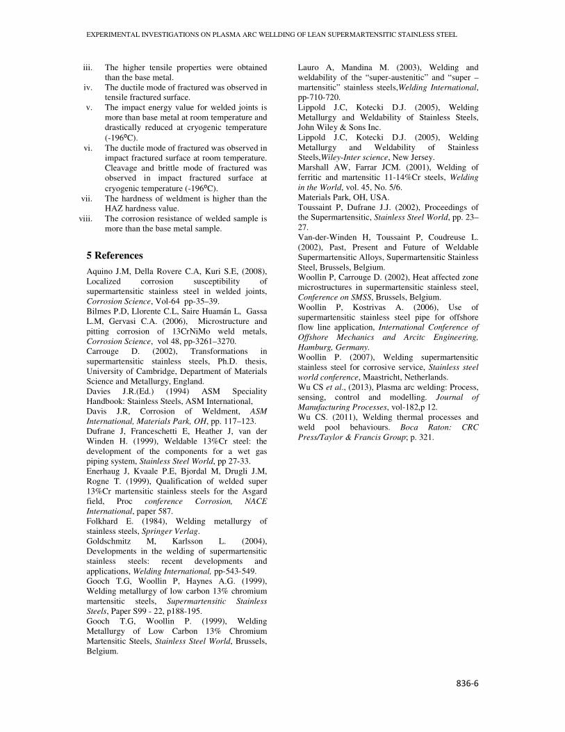
5 References
Aquino J.M, Della Rovere C.A, Kuri S.E, (2008),
Localized corrosion susceptibility of
supermartensitic stainless steel in welded joints,
Corrosion Science, Vol-64 pp-35–39.
Bilmes P.D, Llorente C.L, Saire Huamán L, Gassa
L.M, Gervasi C.A. (2006), Microstructure and
pitting corrosion of 13CrNiMo weld metals,
Corrosion Science, vol 48, pp-3261–3270.
Carrouge D. (2002), Transformations in
supermartensitic stainless steels, Ph.D. thesis,
University of Cambridge, Department of Materials
Science and Metallurgy, England.
Davies J.R.(Ed.) (1994) ASM Speciality
Handbook: Stainless Steels, ASM International,
Davis J.R, Corrosion of Weldment, ASM
International, Materials Park, OH, pp. 117–123.
Dufrane J, Franceschetti E, Heather J, van der
Winden H. (1999), Weldable 13%Cr steel: the
development of the components for a wet gas
piping system, Stainless Steel World, pp 27-33.
Enerhaug J, Kvaale P.E, Bjordal M, Drugli J.M,
Rogne T. (1999), Qualification of welded super
13%Cr martensitic stainless steels for the Asgard
field, Proc conference Corrosion, NACE
International, paper 587.
Folkhard E. (1984), Welding metallurgy of
stainless steels, Springer Verlag.
Goldschmitz M, Karlsson L. (2004),
Developments in the welding of supermartensitic
stainless steels: recent developments and
applications, Welding International, pp-543-549.
Gooch T.G, Woollin P, Haynes A.G. (1999),
Welding metallurgy of low carbon 13% chromium
martensitic steels, Supermartensitic Stainless
Steels, Paper S99 - 22, p188-195.
Gooch T.G, Woollin P. (1999), Welding
Metallurgy of Low Carbon 13% Chromium
Martensitic Steels, Stainless Steel World, Brussels,
Belgium.
Lauro A, Mandina M. (2003), Welding and
weldability of the “super-austenitic” and “super –
martensitic” stainless steels,Welding International,
pp-710-720.
Lippold J.C, Kotecki D.J. (2005), Welding
Metallurgy and Weldability of Stainless Steels,
John Wiley & Sons Inc.
Lippold J.C, Kotecki D.J. (2005), Welding
Metallurgy and Weldability of Stainless
Steels,Wiley-Inter science, New Jersey.
Marshall AW, Farrar JCM. (2001), Welding of
ferritic and martensitic 11-14%Cr steels, Welding
in the World, vol. 45, No. 5/6.
Materials Park, OH, USA.
Toussaint P, Dufrane J.J. (2002), Proceedings of
the Supermartensitic, Stainless Steel World, pp. 23–
27.
Van-der-Winden H, Toussaint P, Coudreuse L.
(2002), Past, Present and Future of Weldable
Supermartensitic Alloys, Supermartensitic Stainless
Steel, Brussels, Belgium.
Woollin P, Carrouge D. (2002), Heat affected zone
microstructures in supermartensitic stainless steel,
Conference on SMSS, Brussels, Belgium.
Woollin P, Kostrivas A. (2006), Use of
supermartensitic stainless steel pipe for offshore
flow line application, International Conference of
Offshore Mechanics and Arcitc Engineering,
Hamburg, Germany.
Woollin P. (2007), Welding supermartensitic
stainless steel for corrosive service, Stainless steel
world conference, Maastricht, Netherlands.
Wu CS et al., (2013), Plasma arc welding: Process,
sensing, control and modelling. Journal of
Manufacturing Processes, vol-182,p 12.
Wu CS. (2011), Welding thermal processes and
weld pool behaviours. Boca Raton: CRC
Press/Taylor & Francis Group; p. 321.