Embed Size (px)
Citation preview

177
VII International Conference on Textile Composites and Inflatable StructuresSTRUCTURAL MEMBRANES 2015
E. Oñate, K.-U.Bletzinger and B. Kröplin (Eds)
IS - ETFE-FOIL PRACTICE - PERFORMANCE TESTS AND PROJECT REALIZATION Experimental investigation on forming design methods of ETFE cushion
VII International Conference on Textile Composites and Inflatable Structures STRUCTURAL MEMBRANES 2015
E. Oñate, K.-U. Bletzinger and B. Kröplin (Eds)
1
EXPERIMENTAL INVESTIGATION ON FORMING DESIGN METHODS OF ETFE CUSHION
B. ZHAO*, W. J. CHEN*, J. H. HU *, Z.Y. QIU* and H. SONG†
* Space Structures Research Center, Shanghai Jiao Tong University, Shanghai, 200030, P.R. China E-mail: [email protected], [email protected], web page: http://www.ssrc.cn
† Shanghai Taiyokogyo Co., Ltd, Shanghai, China, 200030, P.R. China E-mail: [email protected], web page: http://www. taiyokogyo.com.cn
Key words: ETFE cushion; forming design method; 3D patterning; flat patterning; forming test; numerical simulation; membrane shape; stress distribution
Summary: ETFE cushion structure has been widely used as building roof and façade in lots kinds of civil buildings due to its advantages that mainly include transparent, lightweight, durability. There are mainly two design methods to determine the form of ETFE cushion. According to the model used for the analysis process of cutting, the two forming design methods consist of three-dimensional pattering method and flat patterning method. To investigate the forming design methods of ETFE cushion, two methods are presented which are the three-dimensional patterning method based on the zero-stress state and the flat patterning method based on nonlinearity of ETFE material. The physical states and mechanical models are defined for the two methods, respectively. On the basis of the theoretical analysis, experiments and numerical simulations on the two separate ETFE cushions are performed to obtain the shapes, stress distributions and the variations. It is found that, for the three-dimensional patterning model, the maximum difference of the shapes between experimental and numerical results is only 4 mm and the difference of the stress distributions is only 0.4 MPa. For the flat patterning model, a good agreement between the experimental and numerical results is obtained for the initial shape, and it is obtained that the stress decreases when the shape height and the ratio of rise to span increase due to the creep properties of ETFE materials. These findings have validated the proposed forming design methods, which are great importance for the application and development of ETFE cushion.
1 INTRODUCTION
ETFE membrane structure has received considerable attentions in recent years due to its advantages which mainly include transparent, lightweight, durability [1-3]. In 1982, the first ETFE membrane structure was employed for the Arnhem Burger Botanical Garden in Netherlands. Subsequently, the ETFE membrane structure was widely used in Western Europe, especially in Germany and United Kingdom, where the climate is fairly mild. Meanwhile, ETFE cushion enclosures became widely known primarily through the eight domes of the Eden project in 2001 [4], the dome of the Tropical Islands in 2004 [5] and the canopy roof of The Allianz Arena in 2005 [6]. Then the ETFE membrane structure was used gradually spreading all over the world [2]. In 2008 Beijing Olympic Games, ETFE membrane structure

178
B. ZHAO, W. J. CHEN, J. H. HU , Z.Y. QIU, H. SONG
2
was massively introduced into China, which was employed for the National Stadium "Birds Nest" and the National Aquatics Center "Water Cube", the largest ETFE building envelope in the world so far [7]. In the World Exposition 2010 Shanghai, the ETFE structure was employed for Italy Pavilion, Japan Pavilion and Vanke Pavilion.
ETFE membrane structure is often used in the form of air-inflated cushion in the structure of building. According to the model used for the cutting analysis, the forming design methods of ETFE cushion can be divided into two kinds including 3D patterning and flat patterning. The 3D patterning method can be subdivided into two kinds which are 3D model based on the form finding state and 3D model based on zero-stress state [8]. At present, the widely used method in engineering is the 3D patterning method based on the form finding state considering the constant or non-constant strain compensation, which will cause the difference of shape and stress between the analytical value and the actual results. The 3D patterning method has some disadvantages of inconvenient and consumptive, but it is suitable for any forms of ETFE cushion especially for the high rise ETFE cushion. For flat patterning method, through fabricating by using simple flat patterning, ETFE cushion is inflated until the stress approach or pass the first yield point to obtain the desired initial shape due to the creep property of ETFE material [9-12]. The flat patterning method has distinguished advantages of simple fabrication, easy to install, material cost efficiency.
For 3D patterning method, there are many literatures. Robinson-Gayle, Wolfgang and Edward introduced buildings, basic mechanical properties and applications of ETFE foils [13-15]. Christan proposed the air unit and modeled the air for load carrying of ETFE cushion [16]. Moritz investigated comprehensively design and engineering application of ETFE cushion [17-18]. Borgart studied mechanical behavior of multi-layered air inflated cushions through the numerical analysis and experiment [19]. Wu studied ETFE film mechanical property, analysis of ETFE inflated cushion and cushion-form with spring strut to support between layer, as well as test [20-21]. Gu conducted analysis and model experiment of ETFE cushion, and proposed a new way to measure stress [22]. Chen carried out series tests for ETFE cushion experiencing high temperature from 40 degree to 80 degree, as well as ETFE film, which testified the applicability of ETFE cushion in Middle East, and made experiments of ETFE cushion-inflated and studied mechanical behavior and ultimate capacity under normal and low temperature environment [23-26].
For flat patterning method, there is less public work. Schiemann made ETFE bursting test to exhibit nonlinear visco-elastic behavior [27]. Weininger and Schoene made series experiments on ETFE cushion-inflated through flat-patterning and studied post-hardening behavior [28-29]. Boegner studied mechanical properties of ETFE foil and firstly realized plane multi-axial experiment [30]. However, there are very few attentions have been paid on the forming design method of ETFE cushion.
This present paper focuses main effort on the forming design methods of ETFE cushion structure. To investigate the forming design methods of ETFE cushion, two methods are presented which are the three-dimensional patterning method based on zero-stress state and the flat patterning method based on nonlinearity of ETFE material. The physical state and

179
B. ZHAO, W. J. CHEN, J. H. HU , Z.Y. QIU, H. SONG
3
mechanical models are defined for the two methods, respectively. On the basis of the theoretical analysis, experiments and numerical simulations on the two separate ETFE cushions are performed to obtain the shapes, stress distributions and the variations.
2 DESIGN METHOD OF ETFE CUSHION
2.1 Design method and integrated process
Up to now, there are main two design methods to determine the form of ETFE cushion. According to the model used for the analysis of cutting and loading, the forming design methods of ETFE cushion include three-dimensional patterning and flat patterning.
Fig. 1 shows the two design methods and their corresponding integrated procedures: M-1 is the first method based on flat patterning; M-2 is the second method which is same to the traditional design method based on three-dimensional patterning. M-1 is the designed method through flat patterning: M-1① is usually the concept of architectural design; M-1② is the flat cutting sheet; M-1③ is the welding in the plane; M-1④ is the inflating in the factory to retain the reasonable residual strain; M-1⑤ is the inflating in the field; M-1⑥ is the operation of ETFE cushion. M-2 is the traditional design method based on three-dimensional pattern; M-2① is the form-finding state; M-2② is the cutting sheet with curved edges; M-2③ is the welding of 3D surface; M-2④ is the inflating for the leak hunting in the factory; M-2⑤ is the inflating in the field; M-2⑥ is the operation of ETFE cushion.
In summary, M-1 has some advantages of convenient and low cost, but its rise is usually low. To obtain higher rise, the ETFE cushion can be performed with repeated the process of inflated forming. Compared with M-1, M-2 has some disadvantages of inconvenient and consumptive, but this design method is suitable for any forms of ETFE cushion, especially for the large rise ETFE cushion.
Fig. 1. Design methods and integrated processes of ETFE cushion.
2.2 Physical states and mechanical models
The physical states and mechanical models of ETFE cushion are different between the two forming design methods. For the 3D patterning method, the allowable design stress of ETFE foils is limited under the first yield stress with specific safety of factor. Therefore, the initial behavior of ETFE foils during the form-developing process is generally considered and modeled as linear elastic isotropic. However, the mechanical properties of ETFE foils during
180
B. ZHAO, W. J. CHEN, J. H. HU , Z.Y. QIU, H. SONG
4
the forming process of inflated cushion through flat-patterning method are more complex due to the requirement to obtain enough residual strain for the higher rise.
In order to acquire the desired initial surface, the ETFE cushion based on 3D patterning method experiences the processes of form finding, structure analysis and cutting. Fig. 2 shows the physical states of ETFE cushion through 3D patterning. The initial geometric state ① is an unstressed state which contains nodal coordinate, topology and boundary condition without considering the material property. The form-finding analysis is to obtain the form-finding equilibrium state ② with the state ① and pretension. Elastification is to assign real material property to the corresponding structural member to obtain the elasticized equilibrium state ③ with other state parameters same as the state ②. Relaxation analysis is to solve the zero-stress state ④ based on the state ③. The state ④ is an unstressed state obtained by removing the internal pressure. Based on the state ④, the pre-stressed state ⑤ can be solved via pre-stress analysis. Then load analysis can be carried out to obtain the load state ⑥. The cutting and pattern is to obtain the cutting and pattern state ⑦. After completing the manufacture, inflation forming is performed to obtain the configuration pre-stressed state ⑧.
Fig. 2. Physical states and mechanical models of ETFE cushion through 3D patterning
Fig. 3 shows the physical states and mechanical models for the whole design process of the ETFE cushion through the design method of flat patterning. The range of time which contains 0~t3 is the phase of inflated forming, which can be subdivided into three phases: inflating, creep and creep-recovery. This process can be repeated according to the design requirements. The time range of t3~t4 is the phase of storage and transport under 0 kPa. The time range of t4~t5 is the inflating phase in the field. The time range of t5~t6 is the inflated pre-stress state without external loads. The time range of t6~ti is the phase on operation while ETFE cushion resisting dead loads, wind, snow, et al. The stress of ETFE cushion has the same time measurement compared with the internal pressure. The strain of ETFE cushion shows time delay properties and has residual after the deflating to the non-stressed state. This value of residual strain determines the initial rise of ETFE cushion in-service. It can be found that the design method through flat pattering contains the profound mechanical problems. During the whole design process, the ETFE foil experiences complex variation stages including elastic deformation, viscoelastic creep, recovery, and hardening.

181
B. ZHAO, W. J. CHEN, J. H. HU , Z.Y. QIU, H. SONG
5
Fig. 3. Physical states and mechanical models of ETFE cushion through flat patterning.
3 EXPERIMENTATION
To investigate the two proposed forming design methods, two different ETFE cushion models were designed and developed through the two methods to perform the forming test.
3.1 ETFE cushion model
For 3D patterning method, the initial planar dimension of ETFE cushion was square whose side length is 1.5 m. The form of the ETFE cushion was found by EASY Ver. 9.2 [31], and the initial stress (force density) was calculated from expected geometry and normal pressure of 3.5 kPa, that made the ETFE cushion reach nearly the yield strength. This meant that the ETFE cushion could represent the structural performance of practical engineering size. Based on the algorithm of zero-stress state of inflatable membrane structure, the zero-stress state of the ETFE cushion was calculated [8]. As a result, the pre-stresses analysis, load analysis and cutting analysis could be performed based on the obtained zero-stress state. To achieve the smooth surface, the symmetrical pattern was made in the welding process of ETFE cushion. In detail, for each layer of the ETFE cushion, four cutting panels were symmetrical about the diagonal line. The planar dimension and cutting pattern of ETFE cushion are shown Fig. 4.
(a) Planar dimension (b) Cutting pattern (1/2)
Fig. 4. Dimension and cutting of ETFE cushion through 3D patterning.

182
B. ZHAO, W. J. CHEN, J. H. HU , Z.Y. QIU, H. SONG
6
For flat patterning method, the ETFE cushion model was manufactured through the simple plane cutting and welding. As shown in Fig. 5, the planar dimension of the cushion is equilateral triangle whose side length is 2.5 m. The ETFE film with the thickness of 250 m is 250NJ from Japanese Ashi Glass Co. ltd. Due to the limitation of the width of ETFE foils, the upper layer and lower layer are both welded with two sheets. The edges of the two layers are sealed to be a cushion and the seams are 10 mm width. Aluminum extruder profiles are used to connect the edges of ETFE cushion pocketed with 6 PE bars, and tensioned backward with uniform bays of 21 cm to the bracket plates on the upper square tubes of the steel square frame. There are two holes reserved on the lower layer near the corners: one is air inlet/outlet, and the other one sets the pressure sensor.
Fig. 5. Planar dimension of ETFE cushion through flat patterning.
3.2 Experimental setup
For the square ETFE cushion model, the preparatory work was performed to integrate the experimental system. First, the square ETFE cushion model was fixed onto the steel square frame. Then the 3D scanning machine was set up to scan the membrane shape of outer layer which was pasted with target stickers on the grid lines, and the automatic pressure control system was installed through the reserved accesses with sealing performance of valve core on the membrane surface. Fig. 6 shows the experimental system of ETFE cushion through 3D patterning. Finally, the square ETFE cushion model was inflated to 3.5 kPa by means the pressure control system. During the forming test, the internal pressure and membrane shape of the ETFE cushion were measured at the specified time.
Fig. 6. Experimental system of ETFE cushion through 3D patterning.

183
B. ZHAO, W. J. CHEN, J. H. HU , Z.Y. QIU, H. SONG
7
For the triangular ETFE cushion model, the preparatory work was performed to integrate the experimental system. First, the triangular ETFE cushion was fixed onto the steel square frame. Then the dynamic photogrammetry system was set up to acquire the 2D data of ETFE cushion which was pasted with target stickers on the grid lines, and the automatic pressure control system was installed through the reserved accesses with sealing performance of valve core on the membrane surface. Fig. 7 shows the experimental system of ETFE cushion through flat patterning. According to the value of internal pressure, the whole procedure of forming test is divided into three consecutive phases:
(1) Inflating phase. At first, the ETFE cushion was inflated to 4 kPa by using the automatic pressure control system. During the inflating phase, the internal pressure and membrane shape of the ETFE cushion were measured by means of the pressure control system and the dynamic photogrammetry system, respectively.
(2) Creep phase under the constant internal pressure. When ETFE cushion was inflated to 4 kPa, the internal pressure was kept at 4 kPa through the automatic pressure control system. In order to prevent the frequent switch-on shift of the automatic pressure control system, the work range of the internal pressure was set as 3.985~4.015 kPa. It meant that the forming test entered the creep phase whose duration was 24 h. At the specified time, the internal pressure and membrane shape of the ETFE cushion were measured and recorded respectively.
(3) Creep recovery phase. After the creep phase, the ETFE cushion was deflated down to 0.5 kPa to perform the creep recovery phase which was lasted for 24 h. The internal pressure and membrane shape of the ETFE cushion were measured and recorded at the proper time.
Fig. 7. Experimental system of ETFE cushion through flat patterning.
4 RESULTS AND DISCUSSIONS
4.1 3D patterning model
During the forming test of the ETFE cushion through 3D pattering method, the internal pressure and membrane shape were measured by means of the automatic pressure control system and the 3D scanning machine, respectively. According to the experimental results, the stress distribution of the ETFE cushion under different conditions could be calculated based on the equilibrium of inflated pressure and film internal force combining the liner adjustment theory and the force density method. Meanwhile, the numerical simulation for the form
184
B. ZHAO, W. J. CHEN, J. H. HU , Z.Y. QIU, H. SONG
8
finding of ETFE cushion through 3D patterning method was performed to obtain the shape, stress distribution and their variation by using ABAQUS.
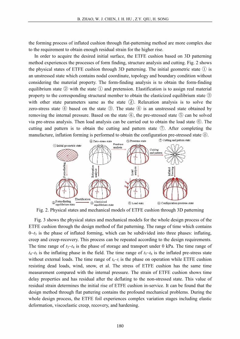
It is significant to discuss the shape of the ETFE cushion because that the shape of the ETFE cushion is the expression of architectural design concept. Fig. 8 shows the shapes of the square ETFE cushion model under 3.5 kPa which is designed through 3D patterning method. A good agreement between the experimental and numerical results is obtained for the shape of the ETFE cushion under 3.5 kPa, that the both change tendency are highly consistent with the same level and gradient slope. However, the difference can be also found that the maximum error value of the two results is 4 mm, and the experimental result is slightly larger due to creep properties of ETFE material.
(a) Numerical simulation (b) Experimental result
Fig. 8. Shapes of ETFE cushion at 3.5 kPa through 3D patterning.
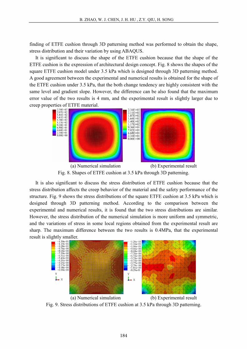
It is also significant to discuss the stress distribution of ETFE cushion because that the stress distribution affects the creep behavior of the material and the safety performance of the structure. Fig. 9 shows the stress distributions of the square ETFE cushion at 3.5 kPa which is designed through 3D patterning method. According to the comparison between the experimental and numerical results, it is found that the two stress distributions are similar. However, the stress distribution of the numerical simulation is more uniform and symmetric, and the variations of stress in some local regions obtained from the experimental result are sharp. The maximum difference between the two results is 0.4MPa, that the experimental result is slightly smaller.
(a) Numerical simulation (b) Experimental result
Fig. 9. Stress distributions of ETFE cushion at 3.5 kPa through 3D patterning.

185
B. ZHAO, W. J. CHEN, J. H. HU , Z.Y. QIU, H. SONG
9
4.2 Flat patterning model
During the forming test of the triangular ETFE cushion model, the internal pressure and membrane shape of the upper layer were measured by means of the automatic pressure control system and the dynamic photogrammetry system, respectively. According to the experimental results, the stress distribution of the ETFE cushion under different conditions could be calculated. Meanwhile, the numerical simulation for the forming process of ETFE cushion through flat-patterning method was performed to obtain the shape, stress distribution and their variation by using ABAQUS.
Fig. 10 shows the shapes of the triangular ETFE cushion model which is designed through flat-patterning method. The measured rise of the ETFE cushion is about 77.4 mm whose ratio of rise to span is about 1/19 when the internal pressure is 0.5 kPa during experimental process of the initial forming. A good agreement between the experimental and numerical results is obtained for the initial shape. However, the result of numerical simulation is slightly bigger, and the change level is smoother. Due to the creep properties of ETFE material, the shape and the ratio of rise to span increase. Finally, and the rise and ratio of rise to span are 121 mm and 1/12, respectively.
(a) Numerical simulation (b) Initial measurement (c) Measurement after creep
Fig. 10. Shapes of ETFE cushion at 0.5 kPa through flat patterning.
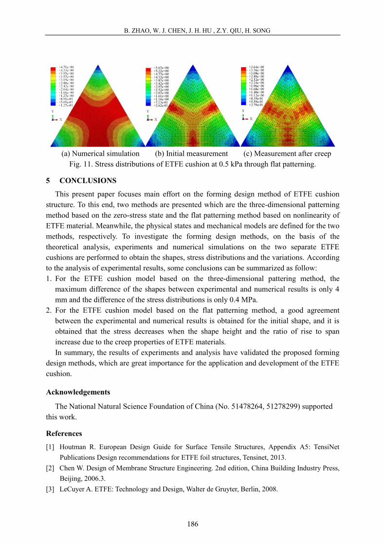
Fig. 11 shows the stress distributions of the triangular ETFE cushion. It is found that the maximum stress of the ETFE cushion is 5.67 MPa when the internal pressure is 0.5 kPa during experimental process of the initial forming. The comparison of stress distribution between experimental result and numerical simulation does not show great difference. In details, the region of large stress obtained from numerical simulation is greater than the experimental result; the maximum stress obtained from the numerical simulation is 4.71 MPa, which is less than the experimental result. Finally, with the creep of ETFE foils, the stress distribution of the ETFE cushion decreases, the maximum stress is about 3.64 MPa.
186
B. ZHAO, W. J. CHEN, J. H. HU , Z.Y. QIU, H. SONG
10
(a) Numerical simulation (b) Initial measurement (c) Measurement after creep
Fig. 11. Stress distributions of ETFE cushion at 0.5 kPa through flat patterning.
5 CONCLUSIONS
This present paper focuses main effort on the forming design method of ETFE cushion structure. To this end, two methods are presented which are the three-dimensional patterning method based on the zero-stress state and the flat patterning method based on nonlinearity of ETFE material. Meanwhile, the physical states and mechanical models are defined for the two methods, respectively. To investigate the forming design methods, on the basis of the theoretical analysis, experiments and numerical simulations on the two separate ETFE cushions are performed to obtain the shapes, stress distributions and the variations. According to the analysis of experimental results, some conclusions can be summarized as follow: 1. For the ETFE cushion model based on the three-dimensional pattering method, the
maximum difference of the shapes between experimental and numerical results is only 4 mm and the difference of the stress distributions is only 0.4 MPa.
2. For the ETFE cushion model based on the flat patterning method, a good agreement between the experimental and numerical results is obtained for the initial shape, and it is obtained that the stress decreases when the shape height and the ratio of rise to span increase due to the creep properties of ETFE materials. In summary, the results of experiments and analysis have validated the proposed forming
design methods, which are great importance for the application and development of the ETFE cushion.
Acknowledgements
The National Natural Science Foundation of China (No. 51478264, 51278299) supported this work.
References
[1] Houtman R. European Design Guide for Surface Tensile Structures, Appendix A5: TensiNet Publications Design recommendations for ETFE foil structures, Tensinet, 2013.
[2] Chen W. Design of Membrane Structure Engineering. 2nd edition, China Building Industry Press, Beijing, 2006.3.
[3] LeCuyer A. ETFE: Technology and Design, Walter de Gruyter, Berlin, 2008.
187
B. ZHAO, W. J. CHEN, J. H. HU , Z.Y. QIU, H. SONG
11
[4] Jones A., Hamilton D., Purvis M., et al. Eden project, Cornwall: design, development and construction. Structural Engineer, 2001, 79(20): 30-36.
[5] Gössling S. Tourism and Development in Tropical Islands: Political Ecology Perspectives, Edward Elgar, 2003.
[6] Sedlacek G., Muller C. The European standard family and its basis. Journal of Constructional Steel Research, 2006, 62(11): 1047-1059.
[7] Chen X., Zhao Z., Zhang X. Application of ETFE membrane structure on national aquatics center (Water Cube), Architecture Technology, 2008, 3: 006.
[8] Zhao J., Chen W., Fu G., et al. Computation method of zero-stress state of pneumatic stressed membrane structure. Science China Technological Sciences, 2012, 55(3): 717-724.
[9] Hu J., Chen W., Zhao B., et al. Uniaxial tensile mechanical properties and model parameters determination of ethylene tetrafluoroethylene (ETFE) foils. Construction and Building Materials, 2015, 75: 200-207.
[10] Hu J., Chen W., Luo R., et al. Uniaxial cyclic tensile mechanical properties of ethylene tetrafluoroethylene (ETFE) foils. Construction and Building Materials, 2014, 63: 311-319.
[11] Charbonneau L., Polak M. A., Penlidis A. Mechanical properties of ETFE foils: testing and modeling. Construction and Building Materials, 2014, 60: 63-72.
[12] Li Y., Wu M. Uniaxial creep property and viscoelastic–plastic modelling of ethylene tetrafluoroethylene (ETFE) foil. Mechanics of Time-Dependent Materials, 2015, 19(1): 21-34.
[13] Robinson-Gayle S., Kolokotroni M., Cripps A., et al. ETFE foil cushions and atria. Construction and Building Materials, 2001; 15: 323-327.
[14] Wolfgang R. Tropical Islands-Implementation of the new ETFE film cushion roofing. Structural Membranes 2005. II Int. conf. on Textile Composites and Inflatable Structures, 2-4 Oct. 2005, Stuttgart, Germany.
[15] Edward M. P., Thorton T. Shaded canopyETFE foil systems, organic and natural forms in building design. ASCE 2010. Structures Congress, 2010, 2864-2870.
[16] Christan H., Annette B., Mike S. ETFE cushions-modelling the air for load carrying. IASS-APCS 2012, May 21-24. FF-446.
[17] Moritz K., Beckert B., Jason W. Transparent lightweight constructionspneumatic ETFE-foil-cushion technology. IASS 2010, Nov. 8-12, 2010, Shanghai, China.
[18] Moritz K., Hafner A. Transparency carried by airpneumatic ETFE-foil-cushion technology. ASCE 2010. Structures Congress, 2010, 2518-2529.
[19] Borgart A. Mechanical behaviour of multi-layered air inflated cushions. Structural Membrane 2007. III Int. conf. on Textile composite and Inflatable Structures, 17-19 Sep. 2007, Barcelona, Spain, pp: 340-343.
[20] Wu M., Liu J., Zhang Q. Experimental study on ETFE foil cushion. Journal of Building Structures, 2008, 29 (6): 126-130.
[21] Wu M., Wu Y., Kim J Y. ETFE foil spring cushion structure and its analytical method. Thin-Walled Structures, 2011, 49(9): 1184-1190.
[22] Gu L., Wang P., Chen S. Experimental study and FEA of ETFE cushion. Journal of Building Structures, 2012, 3 (5): 46-52.

188
B. ZHAO, W. J. CHEN, J. H. HU , Z.Y. QIU, H. SONG
12
[23] Wang K., Chen W., Song H. Experiments on performances of ETFE cushion and properties of ETFE film in high temperature. Spatial Structures, 2011; 17(3): 69-74.
[24] Chen W., Zhao B., He Y. Experiments on mechanical behaviour and performance of ETFE cushion under low temperature environment. Structural Membranes 2011. V Int. Conf. on Textile Composites and Inflatable Structures, 5-7 Oct. 2011, Barcelona, Spain.
[25] Zhao B., Chen W., He Y. Experimental study on double-layer ETFE foil cushion. Spatial Structures, 2013, 19(1): 65-72.
[26] He Y., Chen W., Zhao J. Research on forming theory and test of inflatable membrane structures. Engineering Mechanics. 2013; 30(4): 269-74.
[27] Schiemann L., Hinz S., Stephani M. Tests of ETFE foils under biaxial Stress. Structural Membranes 2009. IV Int. Conf. on Textile Composites and Inflatable Structures, 5-7 Oct. 2009, Stuttgart, Germany.
[28] Schoene L., Weininger F. Engineering of flat shaped membranes. Structural Membranes 2013. VI Int. conf. on Textile composites and Inflatable Structures, 9-11 Oct. 2013, Munich, Germany.
[29] Weininger F., Schoene L., Mesnil R. Post-hardening behavior of ETFE Foils in Pneumatically prestressed membrane constructions. Structural Membranes 2013. VI Int. conf. on Textile composites and Inflatable Structures, 9-11 Oct. 2013, Munich, Germany.
[30] Boegner B. H., Blum R., Koehnlein J. On the mechanical behavior of ETFE-films: elastic range, yielding conditions, hardening, break and the influence on the analysis of ETFE-structures. Structural Membranes 2013. VI Int. conf. on Textile Composites and Inflatable Structures, 9-11 Oct. 2013, Munich, Germany.
[31] Easy Training Manual. Germany: Hi-Technet Gmbh, 2007.