Embed Size (px)
Citation preview
Journal of Engineering
journal homepage: www.joe.uobaghdad.edu.iq
Number 4 Volume 26 April 2020
*Corresponding author
Peer review under the responsibility of University of Baghdad.
https://doi.org/10.31026/j.eng.2020.04.01
2520-3339 © 2019 University of Baghdad. Production and hosting by Journal of Engineering.
This is an open access article under the CC BY4 license http://creativecommons.org/licenses/by /4.0/).
Article received: 1 /7/2019
Article accepted:27/10/2019
Article published:1/4/2020
1
Mechanical and Energy Engineering
Experimental Investigation of Thermal Performance of a Solar Chimney
Provided with a Porous Absorber Plate
Bashaeer A. Kareem Hamood
Researcher
Mechanical Engineering Department,
College of Engineering_ university of Baghdad,
Baghdad, Iraq
Dr. Mohammed A. Nima
Assist. Prof. Dr.Mohammed A. Nima
Faculty of Mechanical Engineering Department,
College of Engineering_ university of Baghdad,
Baghdad, Iraq
ABSTRACT
Experimental investigation of the influence of inserting the metal foam to the solar chimney to
induce natural ventilation are described and analyzed in this work. To carry out the experimental
test, two identical solar chimneys (without insertion of metal foam and with insertion of metal
foam) are designed and placed facing south with dimensions of length× width× air gap (2 m× 1
m× 0.2 m). Four incline angles are tested (20o,30o,45o,60o) for each chimney in Baghdad climate
condition (33.3o latitude, 44.4o longitude) on October, November, December 2018. The solar
chimney performance is investigated by experimentally recording absorber plate and air
temperatures and velocity of air. Results indicated that the using metal foam absorber plate lead
to reducing the mean temperature of absorber plate by 6.7 °C as a result, the values of chimney
outlet air temperature increased. The daily solar chimney efficiency enhanced by 58.7% and the
useful energy received also increased. The existence of metal foam caused higher air velocity at
the exit and increasing in the ventilation rate that the maximum ventilate rate obtained from the
solar chimney is 5.96 1/hr for 27 m3 volume of room at solar irradiance of 730 W/m2 for chimney
incline angle of 60o. The results of the experimental work show that the addition of metal foam to
the solar chimney as an absorber plate is an efficient method to enhance the characteristics of heat
transfer and the thermal performance of the solar chimney in the weather condition of Iraq.
Key words: solar chimney, metal foam, natural ventilation.
Journal of Engineering Volume 26 April 2020 Number 4
2
مدخنة شمسية مزودة بسطح ماص مساميل الحراري داءللأ دراسة تجريبية
محمد عبد الرؤوف نعمةد.
استاذ مساعد
قسم الهندسة الميكانيكية
داجامعة بغد-كلية الهندسة
الكريم حمود عبد بشائر
باحث
قسم الهندسة الميكانيكة
دجامعة بغدا-كلية الهندسة
الخلاصة
تأثير أدخال الرغوه المعدنية الى المدخنة الشمسية في أنتاج التهويه الطبيعية حيث وضحت وحللت م أجراء دراسة تجريبية فيت
الشمسية ) بدون أضافة رغوة معدنية و مع أضافة رغوة معدنية( المداخن تنفيذ التجربة, نوعين منفي هذا البحث الحالي. لكي يتم
(. أربع زوايا ميلان مقدارها x 0.2مx 1م2عمق فجوة الهواء ) xعرض xصممت وتم تثبيتها مواجهه للجنوب بأبعاد طول
(60º ,45º ,30º ,20º 33.3( لكل مدخنة في ظل الظروف المناخية في بغداد ) خط العرضº 44.4ط طول , خº في شهر )
. أختبر أداء المدخنة الشمسية بواسطة تسجيل درجات حرارة الهواء 2019من سنة تشرين الثاني وكانون الاولتشرين الاول و
و السطح الماص و سرعه الهواء عملياً.اظهرت النتائج أنه بأستخدام الرغوة المعدنية كسطح ماص يؤدي الى انخفاض في متوسط
درجات مئوية ونتيجة لذلك, قيم درجات حرارة الهواء الخارج من 6.7صفيحة الماصة للاشعاع االشمسي بمقدار درجة حرارة ال
% والطاقة المفيدة المحصلة ايضاً تزداد. أن وجود 58.7المدخنة تزداد. الكفاءة الحرارية اليومية للمدخنة الشمسية ازدادت بنسبة
اعلى معدل تهوية تم تحصيله من ي معدل التهوية حيثقة الخروج و زيادة فند منطدنية يسبب سرعة هواء اعلى عالرغوة المع
. أظهرت º60عند زاوية ميلان 2واط/م 730عند اشعاع شمسي مقداره 3م27ساعة لحجمم غرفة /1 (5.69)المدخنة الشمسية هو
ة فعالة لتحسين خصائص أنتقال الحرارة والأداء النتائج العملية أن أدخال الرغوة المعدنية الى المدخنة الشمسية كسطح ماص طريق
الحراري للمدخنة الشمسية في ظل الظروف المناخية في العراق.
: مدخنة شمسية, رغوة معدنية, التهوية الطبيعية.الكلمات الرئيسية
1. INTRODUCTION
To minimize the buildings heat gain, also decrease the electrical energy requirement by operating
non-consuming systems for ventilation presented as solar chimney (Chaichan and Kazem, 2011).
The solar chimney device that naturally ventilate the space that can enhancing the buildings energy
efficiency. Various investigation covers this domain experimentally, numerically and
mathematically.
Full scale experimental study was made by (Arce et al., 2009) to investigate solar chimney thermal
performance of 0.3m air gap, 1m wide and 4.5m length under actual weather conditions at day and
night time. The results showed that highest temperature air increase by 7˚C through the designed
chimney was obtained for maximum irradiance of 604 W/m² occurred on 15th of September,2007,
around 13:00h at Tabernas Desert, Almeria province southeastern Spain. As well on same day rate
of air-flow was calculated from range 50 till 374 m3/h. Hence, an average of 177m3/h air flow rate
was obtained at range 0:00 h till 24:00 h and experimental coefficient of discharge found 0.52, Cd
for solar chimney. It was discovered that the wind velocity and thermal gradients caused a
difference in pressure between output and input that influence the solar chimney air flow rate. A
numerical and experimental study was presented by (Karima and Saif, 2012) to conduct solar
chimney heat transfer enhancement in unsteady conditions with inserting phase change material.
Three entrance positions of air was tested for two chimney inclination angles 75o and 90o of
dimension 2.25m length x 0.97m width and 0.15m air gap. The results indicated that the behavior
of solar chimney influence by the entrance position and the best results found with side opening.
It was found the inserting of phase change material enhance the behavior of solar chimney and
expanded the hours of ventilation after the absence of solar irradiance through releasing the energy
stored.

Journal of Engineering Volume 26 April 2020 Number 4
3
(Jianliu and Weihua, 2013) performed an experimental and numerical study to conduct the solar
chimney behavior that inserted into one story building to specify the best inclination angle that
gives maximum ventilation rate. Three types of sizes of solar chimneys were used in the case study
and located in Nanjing at 60˚,45˚,30˚ tilt angles. The results showed that the numerical simulation
was close to the results found experimentally, the glass temperature, the absorber temperature and
the flow-channel temperature all were increased with the increasing of solar radiation intensity. It
was found that the 45˚ tilt angle the optimum for getting maximum ventilation rate in Nanjing, it
was conducted that the mass flow rate at 45˚ tilt angle greater than the mass flow rate at 30˚ and
60˚ tilt angles by 8%, also conclude that the ventilation rate rise with the increasing of air gap to
the height of absorber ratio. (Seytier and Naraghi, 2013) develop an analysis of convection and
radiation heat transfer for solar chimney where the air flow was predicted for different solar
irradiations and structures. A CFD modeling utilizes in the software FLUENT that the designed
solar chimney was 2m height, air gaps 0.1 and 0.2 meters and the inclinations were chosen
60˚,45˚,30˚. The result showed the delivered rate of air flow will be higher for the thicker chimney,
that for doubled air gap thickness there will be increase of 1.7 in flow rate depend on the
considering inclination. A solar chimney model was studied experimentally and numerically
(Ahmed et al., 2015) to investigate chimney performance for various geometric feature under
weather condition of Iraq. The tested model of 2m height and 2m wide was attached to room of
12m3 volume at the roof, three thickness of air gap (0.05, 0.1 and 0.15m) was examined at tilted
angles 15o to 60o. results showed that 60o was the optimum incline angle to achieved highest
ventilate rate, which it higher by 20% from 45o incline angle. The highest produced ventilate rate
from the designed solar chimney was 30 ACH at 750 W/m2 solar irradiance for 60o incline angle
with 0.8 m/s maximum velocity of air for 0.05 m air-gap thickness, also no air-flow reverse was
noticed in 0.15 m gap thickness.
In this research, the heat transfer improvement of solar chimney is tested experimentally and the
improvement is accomplished by adding metal foam to the solar chimney as an absorber plate.
Two identical solar chimneys are designed (without inserting of metal foam and with inserting of
metal foam) examine for different chimney inclination angle and the impact of inserting metal
foam is observed through comparing the collected data from both chimneys.
To the most useful of authors knowledge, the heat transfer improvement of solar chimney with the
integrate of metal foam that investigated experimentally is not showed in the previous work,
specifically in Iraq.
2. EXPERIMANTAL APPARATUS
To carry out the experimental test, two solar chimneys are designed and placed facing south. These
chimneys manufactured from convenient material that available in the market with dimensions of
length× width (2 m× 1 m) and tested for incline angles of (20o,30o,45o,60o), each chimney consists
of glass cover, absorber plate and insulation on the sides and bottom. The chimney gap is 20 cm,
considered based on estimate the thickness of boundary layer (δ) and the displacement
thickness(δ∗) from the following relation (Eckert and Jackson, 1950):
𝛿 = 0.565𝑦(𝐺𝑟)−1/10(Pr)−8/15[1 + 0.494(𝑃𝑟)2
3]1/10 (1)
Where: the prandtl number is (Pr) and the grashof number is (Gr) of the air. The temperature
difference of 20, 30 and 40 oC was taken between surface and intel air temperature.
The displacement thickness can be determined by the following equation (Eckert and Jackson,
1950):

Journal of Engineering Volume 26 April 2020 Number 4
4
𝛿∗ = 0.272 𝛿 (2)
The chimney gap is found double the displacement thickness, for that the proportion of (height/
gap) is roughly equal to eleven (11). That corresponding to the result of proportion indicated from
(Bouchair, 1994) that (the height/chimney gap) ratio was equal (10), to receive highest flow rate
experimentally throughout the structure. The experiment system is shown diagrammatically and
photographically in Fig. 1.
2.1 Solar Chimney
Two solar chimneys are identically designed the first solar chimney with metal foam and the
second chimney without metal foam insertion(conventional) with 10 cm space in between. The
structure of solar chimney is formed by using iron frame of 3 mm thickness with an area of
(2×2.10)𝑚2 , provided at its end with stud to connect the iron frame. The chimney room at the
sides and bottom of each chimney layout is constructed from wood and covered at the top with
glass.
A copper plate of 2.5 mm thickness is used as a solar radiation absorber with an area of (2×1)𝑚2,
and coated with a black matte color to enhance the solar chimney thermal behavior. Absorber
copper plate is riveted to the bottom side of the chimney applying sixteen rivets. The structure is
well insulated by using a glass wool insulator of 2.5 cm thickness at the bottom and sides and
reinforced from the bottom by using a fiber wood of 3 mm thickness. The chimney is installed on
a stand of iron with the same area of the entire structure of (2×2.10)𝑚2 and 80 cm high from the
ground. Initially the chimney is set up at 20o incline angle from the surface, the incline angle is
changed by hand using pulley. A single glass cover of 4 mm thickness is used for each chimney
with an area of (2×1)𝑚2 fitted in the iron frame. The air inters to the chimney room from the
bottom 30 cm above the ground. A wood box is assembled and welded to the iron stand that the
box height 50 cm.
To obtained the anticipated enhance in thermal characteristics of the solar chimney that caused by
inserting metal foam, twelve thermocouples (K-type) are fixed by drilling (2.5mm) V-hole on the
copper absorber wall and soldered to measure the absorber plate temperature for each chimney
(without insertion of metal foam and with insertion of metal foam). Also to obtain the air
temperature variation along the flow direction (K-type) thermocouples are utilized placed in the
mid line of copper plate, six thermocouples located at 10 cm from the glass cover for solar chimney
without insertion of metal foam and twelve thermocouples for solar chimney with insertion of
metal foam are installed above and below the copper foam absorber plate located 5cm from the
glass cover and 5cm from the back wall as shown in Fig. 2.

Journal of Engineering Volume 26 April 2020 Number 4
5
SC with MFI. SC without MFI.

Journal of Engineering Volume 26 April 2020 Number 4
6
Figure 2. Location of thermocouples for absorber wall and air temperatures.
s
Measurement of temperature also involved: the air inlet and outlet temperature and cover
temperature. A Data Logger device with an accuracy of ± 0.4o C over a range of - 50 to 999.9 o C
is used for measuring the temperature where the thermocouples attached to, consisted 12-channel
Figure 1. Experimental Apparatus and Dimension in (cm) .
Temperature
Measurement
Velocity
Measurement
Side view Front view
Without insertion of metal
foam
With insertion of metal foam

Journal of Engineering Volume 26 April 2020 Number 4
7
thermocouple input model BTM-4208SD with a SD card to save the temperature readings along
with time information.
The wind is induced reverse flow that have a significant impact on the chimney air flow rate. To
minimize the wind effect, an extension of wood is constructed at the top with the same area of
chimney gap. The air velocity measurement is achieved by using Hot Wire Anemometer model
DT-8880 that use for low measurement of air velocity with range of 0.1~25 m/s and accuracy
±0.05 m/s. The velocity measurement for exit air flow is taken average of three point for each
chimney. A box of wood setup is assembled to make ensure that the sensor head of the device is
in the correct position and direction. It is installed at the exit with dimension of (10 cm×5 cm×5
cm), a slot is made along the wood box with the same diameter of hot wire probe.
2.2 Construction of Metal Foam, Bonding and positioning.
The absorber plate of 40 PPI copper foam is used with thickness of 1 cm as shown in Fig. 1. The
copper foam absorber plate is formed by assembling four metal foam sheets that coated with black
matte color. The cross sectional area of (1×0.5)𝑚2 for single metal foam sheet. To accomplish
good contact between the metal foam sheets an overlap original bonding method is utilized to
interfere the pieces in appropriate way, that does not influence the metal foam thermal
characteristics and its thermal resistance contact. The sheet is overlap with distance of 2 cm over
the other sheet by using sharp blade and thirty-two aluminum rivets with 15 cm distance between
two consecutive rivets is used to make sure that the copper foam sheets are located in the correct
position. Fig. (3 and 4) shows the elements which previously mentioned.
2.3 Procedure of Experimental Test
The experimental test was take place in Baghdad (33.3o latitude, 44.4o longitude) for this solar
chimney system from October to December 2018. Hourly the data of solar radiation and ambient
temperature are obtained from the Science and Technology Ministry for Baghdad city. For every
half hour the data is obtained where the test started from 09:00 AM and finished at 04:00 PM and.
There is some preparatory work that required to be done Before each test start as followed:
1) Clean chimneys glass covers from dust and humidity.
2) Set the incline angle of chimney by using the system that made for changing the angle.
Figure 3. Overlapping the metal foam.
Figure 4. Schematic drawing for overlapping
the metal foam.
Journal of Engineering Volume 26 April 2020 Number 4
8
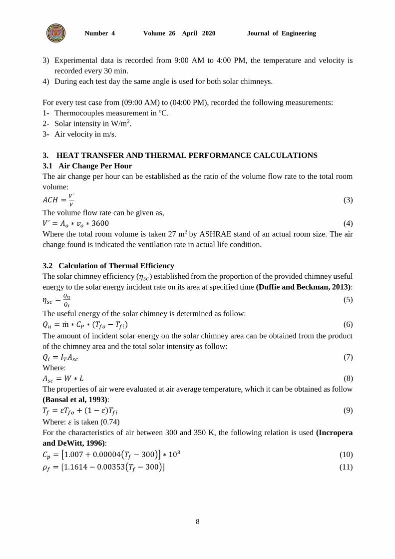
3) Experimental data is recorded from 9:00 AM to 4:00 PM, the temperature and velocity is
recorded every 30 min.
4) During each test day the same angle is used for both solar chimneys.
For every test case from (09:00 AM) to (04:00 PM), recorded the following measurements:
1- Thermocouples measurement in oC.
2- Solar intensity in W/m2.
3- Air velocity in m/s.
3. HEAT TRANSFER AND THERMAL PERFORMANCE CALCULATIONS
3.1 Air Change Per Hour
The air change per hour can be established as the ratio of the volume flow rate to the total room
volume:
𝐴𝐶𝐻 =𝑉´
𝑉 (3)
The volume flow rate can be given as,
𝑉´ = 𝐴𝑜 ∗ 𝑣𝑜 ∗ 3600 (4)
Where the total room volume is taken 27 m3 by ASHRAE stand of an actual room size. The air
change found is indicated the ventilation rate in actual life condition.
3.2 Calculation of Thermal Efficiency
The solar chimney efficiency (𝜂𝑠𝑐) established from the proportion of the provided chimney useful
energy to the solar energy incident rate on its area at specified time (Duffie and Beckman, 2013):
𝜂𝑠𝑐 =𝑄𝑢
𝑄𝑖 (5)
The useful energy of the solar chimney is determined as follow:
𝑄𝑢 = ṁ ∗ 𝐶𝑃 ∗ (𝑇𝑓𝑜 − 𝑇𝑓𝑖) (6)
The amount of incident solar energy on the solar chimney area can be obtained from the product
of the chimney area and the total solar intensity as follow:
𝑄𝑖 = 𝐼𝑇𝐴𝑠𝑐 (7)
Where:
𝐴𝑠𝑐 = 𝑊 ∗ 𝐿 (8)
The properties of air were evaluated at air average temperature, which it can be obtained as follow
(Bansal et al, 1993):
𝑇𝑓 = 휀𝑇𝑓𝑜 + (1 − 휀)𝑇𝑓𝑖 (9)
Where: 휀 is taken (0.74)
For the characteristics of air between 300 and 350 K, the following relation is used (Incropera
and DeWitt, 1996):
𝐶𝑝 = [1.007 + 0.00004(𝑇𝑓 − 300)] ∗ 103 (10)
𝜌𝑓 = [1.1614 − 0.00353(𝑇𝑓 − 300)] (11)

Journal of Engineering Volume 26 April 2020 Number 4
9
4. RESULTS AND DISCUSSION
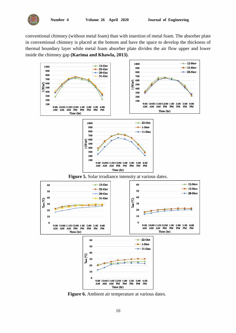
The experimental studies are established for selected days in October, November and December
2018 to examine the thermal performance of the designed solar chimney and the impact of using
metal foam for different inclination angles. The weather condition that involve the solar irradiance
intensity and ambient temperature are presented in Fig. (5 and 6). The parameters that are
investigated: temperature of mean absorber plate (𝑇𝑝), mean air temperature inside the solar
chimney gap, outlet air temperature, absorber wall temperature, air temperature distribution in the
mid space of the gap, mean exit air velocity, air volume flow rate, ACH (air change per hour),
chimney thermal efficiency as well as useful energy.
4.1 Overall Characteristics of Chimneys Temperature
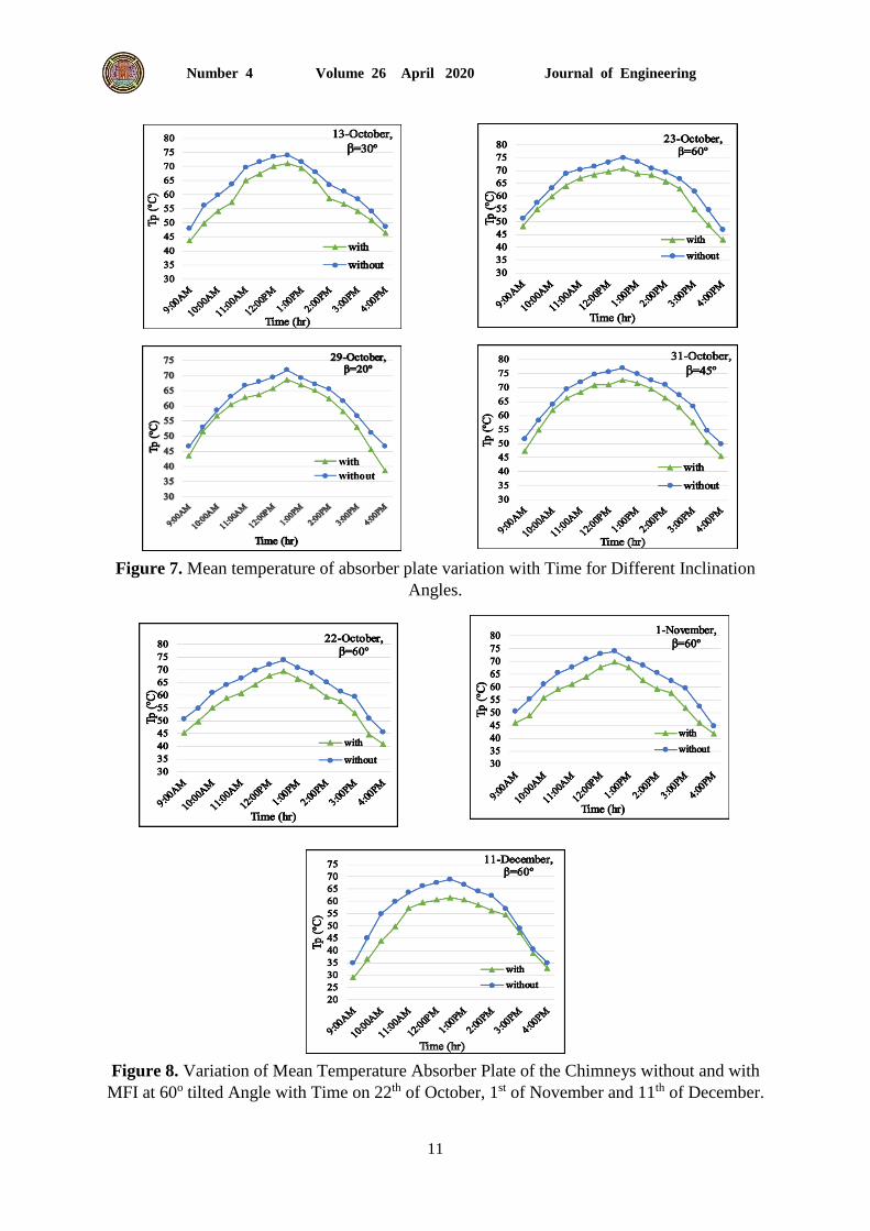
The variation of the mean temperature absorber plate (𝑇𝑝) for the two chimneys without and with
metal foam insertion presents in Fig. 7. with time at chimney inclination angle (20o, 30o, 45o, 60o)
respectively on the 29th, 13th, 31th and 23th of October. It is clear that the behaviour of the absorber
plate temperature similar to that of solar irradiance. With the increase of the intensity of solar
irradiance, the temperature of absorber plate increases then the absorber plate temperature
decreases due to the declination in the intensity of solar radiation as shown in Fig. 5 that started
afterward 01:00 PM. The maximum value of absorber plate mean temperature Tp-with with metal
foam and Tp-without for without metal foam are (69 and 75.9) oC at a tilted angle equal 60o. It clear
that the temperature of metal foam absorber plate is lower when it compares to the temperature of
absorber plate without metal foam. The airflow across the metal foam absorber plate caused a
decreasing in the mean absorber plate temperature, because the air is passed over, through and
lower the metal foam plate while without metal foam the air is passed upper the absorber plate
only. The maximum mean plate temperature variance that obtained between the chimneys attained
to 4.1 ℃ at 20o, 5.5 ℃ at 30o , 6.7 ℃ at 45o and 6.4 ℃ at 60o chimney inclination angle.
Fig. 8. shows the variation of mean temperature absorber plate for the chimneys without and with
metal foam insertion for various dates (October, November and December) with time for 60o
chimney tilted angle. The absorber mean temperature variance between the two solar chimneys
attained to 6.6 ℃ on the 22th of October, 6.7 ℃ on the 1st of November and it reached to 6.2 ℃ on
the 11th of December. It is clear that the influence of metal foam presence inside the chimney is
more effectual in weather condition with high solar radiation intensity that happens in October and
November. When the intensity of solar irradiance increases the buoyancy effect is increased, the
metal foam presences will help with the mixing procedure in the chimney and cause the convection
heat transfer that occurs in the chimney gap to increase and established the required heat transfer
enhancement.
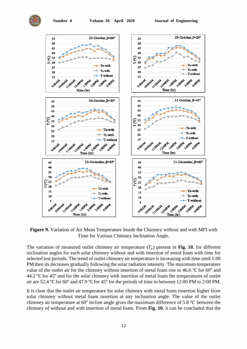
Figs. 9. shows the variation of the mean air temperature measured inside the chimney gap for both
solar chimneys without (𝑇𝑤𝑖𝑡ℎ𝑜𝑢𝑡) and with insertion of metal foam (𝑇𝑢 and 𝑇𝐿), with time for
various chimney inclination angle and different dates. The general behavior of the chimney gap
air temperature is proportional directly to the intensity of solar radiation. Highest temperature of
air flow for the chimney without insertion of metal foam attained to 49.2 ℃ for 60o and 48.6 ℃
for 45o ,although with the insertion of metal foam the solar chimney produces air flow with
temperatures of 44.9 ℃ for 60o and 45.9 ℃ for 45o for period of time 1:00 PM on 23th and 31th of
October. It seems that the air flow temperature in the chimney gap is higher in the case of
Journal of Engineering Volume 26 April 2020 Number 4
10
Figure 6. Ambient air temperature at various dates.
Figure 5. Solar irradiance intensity at various dates.
conventional chimney (without metal foam) than with insertion of metal foam. The absorber plate
in conventional chimney is placed at the bottom and have the space to develop the thickness of
thermal boundary layer while metal foam absorber plate divides the air flow upper and lower
inside the chimney gap (Karima and Khawla, 2013).
Journal of Engineering Volume 26 April 2020 Number 4
11
Figure 8. Variation of Mean Temperature Absorber Plate of the Chimneys without and with
MFI at 60o tilted Angle with Time on 22th of October, 1st of November and 11th of December.
Figure 7. Mean temperature of absorber plate variation with Time for Different Inclination
Angles.
Journal of Engineering Volume 26 April 2020 Number 4
12
Figure 9. Variation of Air Mean Temperature Inside the Chimney without and with MFI with
Time for Various Chimney Inclination Angle.
The variation of measured outlet chimney air temperature (𝑇𝑜) present in Fig. 10. for different
inclination angles for each solar chimney without and with insertion of metal foam with time for
selected test periods. The trend of outlet chimney air temperature is increasing with time until 1:00
PM then its decreases gradually following the solar radiation intensity. The maximum temperature
value of the outlet air for the chimney without insertion of metal foam rise to 46.6 ℃ for 60o and
44.2 ℃ for 45o and for the solar chimney with insertion of metal foam the temperatures of outlet
air are 52.4 ℃ for 60o and 47.9 ℃ for 45o for the periods of time in between 12:00 PM to 2:00 PM.
It is clear that the outlet air temperature for solar chimney with metal foam insertion higher from
solar chimney without metal foam insertion at any inclination angle. The value of the outlet
chimney air temperature at 60o incline angle gives the maximum difference of 5.8 ℃ between the
chimney of without and with insertion of metal foam. From Fig. 10. it can be concluded that the

Journal of Engineering Volume 26 April 2020 Number 4
13
impact of metal foam produced an increment in the chimney outlet air temperature. This behavior
presents the proof of enhancement in thermal performance that accomplished when adding the
metal foam to the system.
4.2 Distribution of Wall and Air Temperatures
The behavior of distributed temperature of the wall along the centre line
(𝑇𝑝1, 𝑇𝑝2, 𝑇𝑝3, 𝑇𝑝4, 𝑇𝑝5 𝑎𝑛𝑑 𝑇𝑝6) present in Fig. 11. For both chimneys without and with insertion
of metal foam for 60o incline angle on 8th of December. It is clear that due to the continuous heating
and increasing in the temperature of the flowing air throughout the solar chimney, the temperature
of wall rises in the direction of flow. The highest values obtained are 69 ℃ for the chimney without
metal foam and 64 ℃ for the chimney with metal foam at afternoon and, respectively. It can be
concluded that the variance between the temperatures wall along the centre line for each solar
chimney increases with the increase of solar irradiance intensity and the influence of adding metal
foam in the chimney is more phenomenal. The metal foam existence has influence to rise the
ventilate rate of the solar chimney and this causes a higher temperature difference value in the
afternoon compared with the earlier morning.
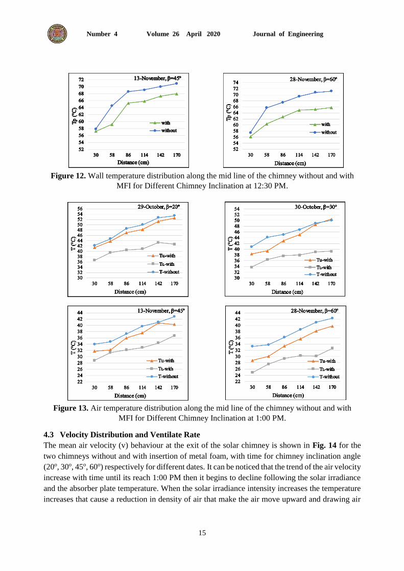
Fig. 12 shows the distribution of the temperature of wall chimney absorber plate along the centre
line for each solar chimney, without and with insertion of metal foam for various chimney
inclination angle (20o,30o,45o and 60o) on the 29th and 30th of October and 13th and 28th of
November.
Fig. 13 shows the distribution of the temperature of air for the chimney along the centre line at six
point for each solar chimney without insertion of metal foam (𝑇𝑤𝑖𝑡ℎ𝑜𝑢𝑡) and with insertion of metal
foam for upper air temperature (𝑇𝑢) and lower air temperature (𝑇𝐿) for various chimney inclination
angle (20o,30o,45o and 60o) on the 29th and 30th of October and 13th and 28th of November. It is
clear that the temperature of air increases in the direction of flow due to the continuous heating
throughout the solar chimney. It can be noticed that the air temperature values at the end higher
compared to the air temperature at entrance. The metal foam divides the air flow inside the
chimney gap and it can be seen that the temperature of air at upper space is higher compared with
the temperature of air at lower space. This is because the upper air subjected directly to the fallen
solar irradiance while the lower air partially exposed to the sunlight.

Journal of Engineering Volume 26 April 2020 Number 4
14
Figure 10. Variation of Outlet Air Temperature of the Chimney without and with MFI with
Time for Different Chimney Inclination Angle on the 23rd ,24th, 28th, and 29th of October.
Figure 11. Wall temperature distribution along the mid line of the chimney without and with
MFI for different time for 60o inclination angle.
.
Journal of Engineering Volume 26 April 2020 Number 4
15
Figure 12. Wall temperature distribution along the mid line of the chimney without and with
MFI for Different Chimney Inclination at 12:30 PM.
Figure 13. Air temperature distribution along the mid line of the chimney without and with
MFI for Different Chimney Inclination at 1:00 PM.
4.3 Velocity Distribution and Ventilate Rate
The mean air velocity (v) behaviour at the exit of the solar chimney is shown in Fig. 14 for the
two chimneys without and with insertion of metal foam, with time for chimney inclination angle
(20o, 30o, 45o, 60o) respectively for different dates. It can be noticed that the trend of the air velocity
increase with time until its reach 1:00 PM then it begins to decline following the solar irradiance
and the absorber plate temperature. When the solar irradiance intensity increases the temperature
increases that cause a reduction in density of air that make the air move upward and drawing air
Journal of Engineering Volume 26 April 2020 Number 4
16
from the ambient and ventilate the space. It clear that the air velocity with insertion of metal foam
is higher than for without metal foam solar chimney. The maximum values of solar chimney mean
air velocity without insertion of metal foam are 20 𝑐𝑚/𝑠 for 60o and 19.3 𝑐𝑚/𝑠 for 45o and for
solar chimney with insertion of metal foam the mean air velocity are 22.3 𝑐𝑚/𝑠 for 60o and
22𝑐𝑚/𝑠 for 45o on the 23th and 31th of October. The disturbance that made by existence of metal
foam, additionally the increase in the surface-area lead to increase heat transfer among the surface
area with the moving fluid (air) inside chimney room. That cause a higher air velocity at the exit
and increasing in the ventilation rate that the enhancement can be conducted from the insertion of
metal foam.
Fig. 15 presents The variation for the volume flow rate (𝑉′) for the two chimneys without and
with insertion of metal foam, with time for 60o chimney inclination angle on 23th of October and
1st of November. It noticed from the figure that the ventilate rate (air volume flow rate) is greater
for solar chimney with metal foam insertion compared with the solar chimney without metal foam
insertion. The maximum value of mean air volume flow rate obtained for solar chimney with
insertion of metal foam that reaches 160.5 𝑚3/ℎ𝑟 for 60o on the 1st of November as result, 5.96
1/hr air change per hour is achieved.
4.4 Solar Chimney Thermal Efficiency and Useful Energy
The difference between each solar chimney without and with insertion of metal foam thermal
efficiency shows in Fig. 16, with time on 23th and 31th of October. The trend of the thermal
efficiency can be noticed its follows the solar radiation that the thermal efficiency of solar chimney
increases with the increase of intensity of solar radiation. Because of the ambient temperature rise
continuously and that lead to decrease in the losses of heat. It clearly noticed in Fig. 16 the enhance
accomplished by using the metal foam in the solar chimney. That the maximum value of chimney
thermal efficiency for solar chimney without insertion of metal foam attained to 42% for 60o and
30.9% for 45o on the 23th and 31th of October, respectively at 01:00 PM and for with insertion of
metal foam solar chimney the maximum values of chimney thermal efficiency are 53.6% for 60o
and 48.8% for 45o on the 23th and 31th of October.
Fig. 17 present the distribution of useful energy received from the solar chimneys without and
with insertion of metal foam for every hour. The trend of the useful energy follows the solar
irradiance that increases with the increase of solar irradiance and start to decrease due to the solar
irradiance decreasing. It can be noticed that the energy obtained from the solar chimney with the
insert of metal foam higher than from the solar chimney without metal foam. It is clear the effect
of inserting the metal foam as an absorber plate to the solar chimney where the energy achieved
from the solar chimney has been effected by the heat transfer characteristics enhancements. The
highest values of chimney useful energy without insertion of metal foam are 540.8W for 60o and
477 W for 45o and for with insertion of metal foam the useful energy received are 812.5 W for 60o
and 892.7 W for 45o on the 23th and 31th of October
The highest daily solar chimney efficiency enhancement present in Fig. 18. That the values of
daily solar chimney efficiency enhancement for 20o and 30o chimney inclination angles 41.2% and
47.8%, respectively and in the case of 45o and 60o chimney inclination angles the enhancement
rise to 53.6% and 58.7%, respectively.

Journal of Engineering Volume 26 April 2020 Number 4
17
Figure 14. Variation of air velocity for the solar chimney without and with MFI with Time
for Different Inclination Angles on October.
Figure 15. Variation of volume flow rate for the solar chimney without and with MFI with
Time for 60o Inclination Angles on 23th of October and 1st of November.
Figure 16. Variation of chimney thermal efficiency of the solar chimney without and with
MFI with Time for 60o and 45o Inclination Angles on 23th and 31th of October.

Journal of Engineering Volume 26 April 2020 Number 4
18
Figure 17. Variation of chimney useful energy of the solar chimney without and with MFI
with Time for 60o and 45o Inclination Angles on 23th and 31th of October.
Figure 18. Chimney thermal efficiency enhancement per day with chimney inclination angles.
5. CONCLUSION
The solar chimney has been studied experimentally to conduct natural ventilation and investigate
the enhancement in the characteristics of heat transfer and the solar chimney thermal performance
that was achieved by integrating the copper foam absorber plate in the solar chimney. The study
is carried out on two solar chimneys with insertion of metal foam and without metal foam under
Iraqi weather condition with different chimney inclination angles in October, November and
December 2018. The following conclusions are summarized from the present investigation.
1- Thermal performance of solar chimney is greatly influenced by the solar irradiance and the
incline angle, especially at higher tilted angle.
2- A comparison for the data that obtained from the two chimneys with insertion of metal foam
and without insertion of metal foam. The addition of metal foam produced the following
effects:
a) Reducing the mean temperature of absorber plate value and an increment in the values of
chimney outlet air temperature. The highest reduction in the plate temperature that
obtained experimentally is 6.7 ℃ at 45o chimney inclination angle. The highest increase
in the air temperature that obtained through the whole experimental is 5.8 ℃ at 60o
chimney inclination angle.
b) Increase the mean outlet air velocity through the whole experimental by 4 cm/s on 1st of
November for 739 W/m2 solar irradiance intensity at 12:00 PM for 60o incline angle. That
enhance by 22.6%
Journal of Engineering Volume 26 April 2020 Number 4
19
c) An increasing in the air volume flow rate and air change per hour that the highest values
obtained are 160.56 m3/hr and 5.96 1/hr, respectively at 60o incline angle on 1st of
November.
d) An increasing in the chimney thermal efficiency and useful energy that the maximum
enhancement by 87.14% on 31th of October at 12:00 PM for 45o inclination angle.
e) Enhance the daily chimney thermal efficiency that for 20o and 30o chimney inclination
angles 41.2% and 47.8%, respectively and in the case of 45o and 60o chimney inclination
angles the enhancement rise to 53.6% and 58.7%, respectively.
3- The enhancement that achieved by the existence of metal foam is decreased as the chimney
inclination angle is decreased and as the solar radiation intensity decreased.
4- The results of the experimental work show that the addition of metal foam to the solar chimney
as an absorber plate is an efficient method to enhance the characteristics of heat transfer and
the thermal performance of the solar chimney in the weather condition of Iraq mainly for
higher intensity of solar irradiance and higher chimney inclination angle.
REFERENCES
Ahmed, A., I., Jalal, M., Jalil, Sabah, T., Ahmed, 2015. Induced flow for ventilation and
cooling by a solar chimney. Renewable energy, (78), pp., 236-244.
Arce, J., Jimenez, M., J., Guzman, J., D., Heras, M.R., Alvarez, G., Xaman, J., 2009.
Experimental study for natural ventilation on a solar chimney. Renewable Energy, (34),
pp., 2928-2934.
2009. ASHRAE HANDBOOK FUNDAMENTALS.
Bansal, N., K., Mathur, R., Bhandari, M., S., 1993. Solar chimney for enhanced stack
ventilation. Building and Environment, (28), PP., 373-377.
Bouchair, 1994. Solar chimney for promoting cooling ventilation in southern Algeria.
Building Service Engineering Research and Technology, (15), PP., 81-93.
Chaichan, M., T., and Kazem, H., A., 2011. Thermal storage comparison for variable
basement kinds of a solar chimney prototype in Baghdad - Iraq weathers. International
journal of Applied Science (IJAS), (2), PP., 12-20.
Duffie, J.A. and Beckman, W. A, 2013. Solar Engineering of Thermal Process. Wiley
Interscience Publications, New York: John Wiley and Sons.
Eckert, E., and Jackson, T., W., 1950. Analysis of turbulent free convection boundary layer
on flat plate. (Report 1015, supersedes NACA TN 2207).
Incropera, F., P., and Dewitt, D., P., 1996. Fundamentals of Heat and Mass Transfer. 4th
Edition, John Wiley.
Jianliu, X., and Weihua, L., 2013. Study on solar chimney used for room natural ventilation
in nanjing. Energy and Buildings, (66), PP., 467-469.
Karima, E., A., and Saif, W., M., 2012. Experimental and numerical studies of solar
chimney for natural ventilation in Iraq. Energy and Buildings, (47), PP., 450-457.
Karima, E., A., and Khawla, N., H., 2013. Numerical Study of Solar Chimney with
Absorber at Different Locations. Journal of Engineering, (19), PP., 485-499.
Journal of Engineering Volume 26 April 2020 Number 4
20
Seytier, C., and Naraghi, M., 2013. Combined convective-radiative thermal analysis of an
inclined rooftop solar chimney. Journal of Solar Energy Engineering, (135),
PP. 011009-8.
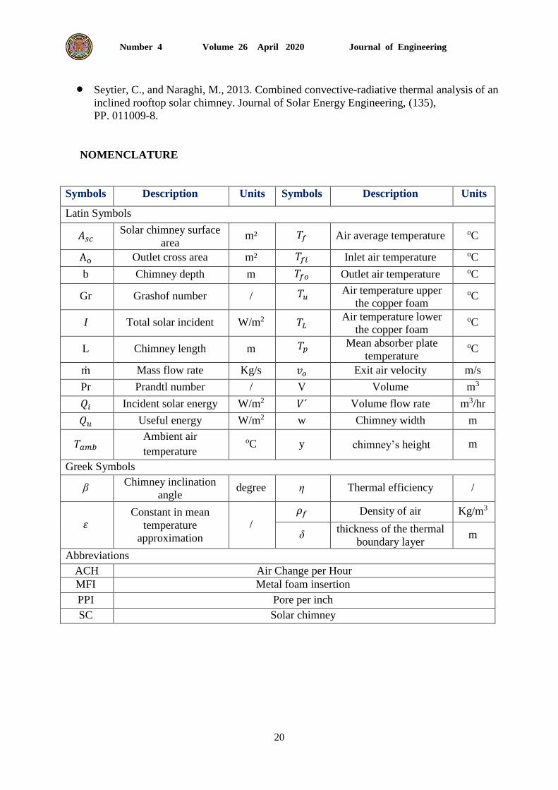
NOMENCLATURE
Symbols Description Units Symbols Description Units
Latin Symbols
𝐴𝑠𝑐 Solar chimney surface
area m² 𝑇𝑓 Air average temperature oC
Ao Outlet cross area m² 𝑇𝑓𝑖 Inlet air temperature oC
b Chimney depth m 𝑇𝑓𝑜 Outlet air temperature oC
Gr Grashof number / 𝑇𝑢 Air temperature upper
the copper foam oC
I Total solar incident W/m2 𝑇𝐿 Air temperature lower
the copper foam oC
L Chimney length m 𝑇𝑝 Mean absorber plate
temperature oC
ṁ Mass flow rate Kg/s 𝑣𝑜 Exit air velocity m/s
Pr Prandtl number / V Volume m3
𝑄𝑖 Incident solar energy W/m2 𝑉´ Volume flow rate m3/hr
𝑄𝑢 Useful energy W/m2 w Chimney width m
𝑇𝑎𝑚𝑏 Ambient air
temperature oC y chimney’s height m
Greek Symbols
β Chimney inclination
angle degree η Thermal efficiency /
휀 Constant in mean
temperature
approximation
/
𝜌𝑓 Density of air Kg/m3
δ thickness of the thermal
boundary layer m
Abbreviations
ACH Air Change per Hour
MFI Metal foam insertion
PPI Pore per inch
SC Solar chimney