Embed Size (px)
Citation preview

Brisid IsufiFaculdade de Ciências e Tecnologia, UNL
Supervisors: António M. P. Ramos
Válter J. G. Lúcio
Experimental investigation of the behavior of flat
slabs with studs as shear reinforcement
Department of Civil Engineering
Caparica, March 7, 2018

EDIFICE Conference 2018Department of Civil Engineering
Contents
• Introduction
• Experimental campaign
• Main results and conclusions

EDIFICE Conference 2018Department of Civil Engineering
Introduction
In seismic regions:
Flat slabs: slabs directly supported on the columns, i.e., without beams.
advantages disadvantages
freedom in interior
architectural design
less labour intensive
installations: electrical,
HVAC, plumbing etc.
simpler formwork, simpler
reinforcement layout
reduced overall building
height and mass
risk of progressive collapse
uncertain ultimate drift
not entirely covered
by design codes
existing buildings
EDIFICE Conference 2018Department of Civil Engineering
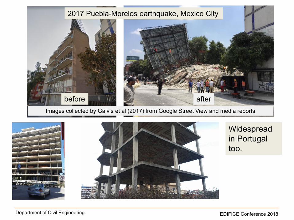
before after
Images collected by Galvis et al (2017) from Google Street View and media reports
Widespread
in Portugal
too.
2017 Puebla-Morelos earthquake, Mexico City

EDIFICE Conference 2018Department of Civil Engineering
How to enhance punching shear strength?
+ high strength concrete, fibre reinforced concrete etc.
+ other proprietary
products.
In this research:
+ drop panels, thickening;

EDIFICE Conference 2018Department of Civil Engineering
Studs as shear reinforcement
Headed studs are among the most efficient means of enhancing the
punching shear strength of flat slabs (supported by several monotonic and
cyclic loading tests).
easy to install
good anchorage
conditions
available tests indicate
that studs perform
better than stirrups
difficult to produce on site
considerable differences
between the specimens
found in literature
+ -
New tests proposed in
this research
Why studs?1) continuation of the research effort of the
last few years at FCT/UNL;
2) contribution to the available literature.

EDIFICE Conference 2018Department of Civil Engineering
Experimental campaign
1.85m
thickness: 150mm- 1 reference specimen C-Ref
- 4 flat slab specimens with stud
shear reinforcement
- naming convention:
C-SSRn
Type of shear reinforcement:
SSR=Shear Studs Reinforcement
n = no. of perimeters of
shear reinforcement
Type of loading: C- horizontal
reversed cyclic loading
C-Ref
C-SSR3
C-SSR5a
C-SSR5b
C-SSR5c
No shear reinforcement
Studs shear reinforcement
varying gravity load:
a) in absolute value (in kN)
b) as a fraction of the
concentric punching
shear resistance (GSR)

EDIFICE Conference 2018Department of Civil Engineering
Longitudinal reinforcement
- The same longitudinal
reinforcement for all
specimens.
- Top reinforcement
ratio ≈1%
- Instrumented bars as
shown in the figure
- Cover: 20mm
A
A

EDIFICE Conference 2018Department of Civil Engineering
Shear reinforcement layout
C-SSR3 C-SSR5...
The same EC2 outer perimeter.

EDIFICE Conference 2018Department of Civil Engineering
Production of studs
C-SSR3 C-SSR5...
70mm
Ø8mm

EDIFICE Conference 2018Department of Civil Engineering

EDIFICE Conference 2018Department of Civil Engineering
column
slab edge

EDIFICE Conference 2018Department of Civil Engineering

EDIFICE Conference 2018Department of Civil Engineering
Materials
Main mechanical properties
of concrete and steel are
determined by laboratory
tests.
Longitudinal reinforcement yield strength ≈ 540 MPa
Shear reinforcement yield strength ≈ 485 MPa
Specimen fc (MPa)
C-Ref 62.3
C-SSR3 41.2
C-SSR5a 27.0
C-SSR5b 57.6
C-SSR5c 69.9

EDIFICE Conference 2018Department of Civil Engineering
Test setup
1.85m
thickness: 150mm
This setup ensures:
- equal vertical displacements at the opposite slab borders;
- equal magnitude shear forces, bending moments and rotations at the slab
borders;
- mobility of the line of inflection location along the longitudinal direction;
- application of high vertical load ratios.

EDIFICE Conference 2018Department of Civil Engineering
Loading protocol
The loading sequence:
1) application of gravity load until a target GSR is
reached (resistance based on Eurocode 2):
55% for C-Ref, C-SSR3, C-SSR5a, C-SSR5b
65% for C-SSR5c
2) application of reversed horizontal
cyclic displacements until failure.
-140
-120
-100
-80
-60
-40
-20
0
20
40
60
80
100
120
140
-7.0%
-6.0%
-5.0%
-4.0%
-3.0%
-2.0%
-1.0%
0.0%
1.0%
2.0%
3.0%
4.0%
5.0%
6.0%
7.0%
dri
ftra
tio
[%]
ho
rizo
nta
ldis
pla
ce
me
nt
[mm
]
time
gravity load
Modified sequence for C-SSR5b:
1) Phase I: protocol followed until 3% drift
2) Phase II: specimen unloaded, protocol
restarted and followed until failure.
Purpose: to observe the strength and stiffness
of a flat slab – column assembly that has been
previously subjected to a major seismic event.

EDIFICE Conference 2018Department of Civil Engineering
Instrumentation
Strains:
-Strain gauges in 15 studs of C-SSR3 and
in 25 studs of C-SSR5 specimens
-Four top bars at two locations;
-Two bottom bars at two locations;
Displacements and rotations:
- 18 displacement transducers
- 1 disp. transducer at the actuator
- 2 inclinometers at borders
Forces:
- 4 load cells for gravity loading;
- 2 load cells at test setup struts;
- 1 actuator load cell

EDIFICE Conference 2018Department of Civil Engineering
Time-lapse video of the cyclic loading test of specimen C-SSR5c

EDIFICE Conference 2018Department of Civil Engineering
Results: C-Ref
-120 -80 -40 0 40 80 120
-60
-40
-20
0
20
40
60
-6 -4 -2 0 2 4 6
-120
-80
-40
0
40
80
120
Drift (%)
Un
ba
lan
ce
dM
om
en
t(k
Nm
)
Ho
rizon
talF
orc
e(k
N)
Horizontal Displacement (mm)
-Failure mode: punching shear failure
-Maximum attained drift ratio: 1.0%.

EDIFICE Conference 2018Department of Civil Engineering
Results: C-SSR3
-Failure mode: punching outside the
shear reinforced zone
-Maximum attained drift ratio: 4.0%.
-140-120-100 -80 -60 -40 -20 0 20 40 60 80 100 120 140-80
-60
-40
-20
0
20
40
60
80-7 -6 -5 -4 -3 -2 -1 0 1 2 3 4 5 6 7
-160
-120
-80
-40
0
40
80
120
160
Drift (%)
Un
ba
lan
ced
mo
me
nt
(kN
m)
Ho
rizo
nta
lfo
rce
(kN
)
Horizontal displacement (mm)

EDIFICE Conference 2018Department of Civil Engineering
Results: C-SSR5a
-Failure mode: gradual loss of strength.
-Maximum drift: 6.0%, no punching
failure.
-140-120-100 -80 -60 -40 -20 0 20 40 60 80 100 120 140-80
-60
-40
-20
0
20
40
60
80-7 -6 -5 -4 -3 -2 -1 0 1 2 3 4 5 6 7
-160
-120
-80
-40
0
40
80
120
160
Drift (%)
Un
ba
lan
ced
mo
me
nt
(kN
m)
Ho
rizo
nta
lfo
rce
(kN
)
Horizontal displacement (mm)
Bottom face:
This is the slab with the smallest
Vg (although the same GSR)

EDIFICE Conference 2018Department of Civil Engineering
Results: C-SSR5b
-Failure mode: punching failure outside the shear reinforced zone
-Maximum drift prior to punching failure: 5.5%.
-120 -80 -40 0 40 80 120
-60
-40
-20
0
20
40
60
-6 -4 -2 0 2 4 6
-120
-80
-40
0
40
80
120
Phase I
Phase II
Drift (%)
Un
ba
lan
ce
d M
om
en
t (k
Nm
)
Ho
rizo
nta
l F
orc
e (
kN
)
Horizontal Displacement (mm)

EDIFICE Conference 2018Department of Civil Engineering
Results: C-SSR5c
-Failure mode: punching failure outside the shear reinforced zone
-Maximum drift prior to punching failure: 4.0%.
-120 -80 -40 0 40 80 120
-60
-40
-20
0
20
40
60
-6 -4 -2 0 2 4 6
-120
-80
-40
0
40
80
120
Drift (%)
Un
ba
lan
ce
dM
om
en
t(k
Nm
)
Ho
rizon
talF
orc
e(k
N)
Horizontal Displacement (mm)

EDIFICE Conference 2018Department of Civil Engineering
Comparison
0 20 40 60 80 100 120 1400
10
20
30
40
50
60
700 1 2 3 4 5 6 7
0
20
40
60
80
100
120
140
C-Ref
C-SSR3
C-SSR5a
C-SSR5b (envelope)
C-SSR5c
Drift (%)
Un
ba
lan
ce
d M
om
en
t (k
Nm
)
Ho
rizo
nta
l F
orc
e (
kN
)
Horizontal Displacement (mm)

EDIFICE Conference 2018Department of Civil Engineering
Conclusions
• Significant drift capacity enhancement was achieved by specimens with studs;
• Increase of gravity loads led to decrease of the ultimate drift;
• Extent of shear reinforcement influenced drift capacity (specimen C-SSR3 vs. C-SSR5b);
• Post-earthquake behaviour: specimen C-SSR5bsustained high drifts (5.5%);

EDIFICE Conference 2018Department of Civil Engineering
Thank you!


![EC2 - Concrete Centre [Flat Slabs - 2007]](https://img.pdfslide.us/doc/110x75/551350094a7959b1478b45dc/ec2-concrete-centre-flat-slabs-2007.jpg)