Embed Size (px)
Citation preview
1
Experimental investigation of the applicability of a thermoelectric generator to recover waste heat from a
combustion chamber
P. Aranguren, D. Astrain*, A. Rodríguez, A. Martínez
Departamento de Ingeniería Mecánica, Energética y de Materiales, Universidad Pública de Navarra, Pamplona (Navarra), España
*Tel: +34 948 169597, Fax: +34 948 169099, e-mail: [email protected]
Keywords: thermoelectricity, prototype, combustion chamber, waste heat
Abstract
A thermoelectric generator prototype has been built; it produces 21.56 W of net power, the produced thermoelectric power minus the consumption of the auxiliary equipment, using an area of 0.25 m2 (approximately 100 W/m2). The prototype is located at the exhaust of a combustion chamber and it is provided with 48 thermoelectric modules and two different kinds of heat exchangers, finned heat sinks and heat pipes. Globally, the 40 % of the primary energy used is thrown to the ambient as waste heat; one of the many different applications in which thermoelectricity can be applied is to harvest waste heat to produce electrical power.
Besides, the influence on the thermoelectric and on the net power generation of key parameters such as the temperature and mass flow of the exhaust gases, the heat dissipation systems in charge of dispatching the heat into the ambient and the consumption of the auxiliary equipment has been studied. In terms of heat dissipation, the heat pipes outperform the finned dissipators, a 43 % more net power is obtained.
Nomenclature �� Absolute error �� Relative error ϵ Emissivity ���� Net efficiency �� Efficiency of the thermoelectric generator ��� ��� Global efficiency σ Stefan-Boltzmann coefficient W/m2K4 �� External area m2 ���� Radiation area m2 �� Specific heat J/kgK
e Thickness m ℎ� Exterior convection coefficient W/m2K ℎ��� Radiation coefficient W/m2K ���� Intensity consumed by the auxiliary equipment A �� Intensity produced by the TEMs A � Thermal conductivity W/mK �� ��� Mass flow of the exhaust gases kg/s ��� Heat emitted to the ambient by the TEG W ��� Heat absorber by the TEG W
© 2015. This manuscript version is made available under the CC-BY-NC-ND 4.0 license http://creativecommons.org/licenses/by-nc-nd/4.0/
2
� �� Conduction thermal resistance K/W � �� Contact thermal resistance K/W � �! Convection thermal resistance K/W �"� Thermal resistance of the isolation K/W �# Load resistance Ω ���� Radiation thermal resistance K/W �� Interior resistance of the TEM K/W $�##%& Temperature of the cold side of the lower levels finned dissipators ⁰C $�##�' Temperature of the cold side of the lower levels heat pipes ⁰C $�(#%& Temperature of the cold side of the upper levels finned dissipators ⁰C $�##%& Temperature of the hot side of the lower levels finned dissipators ⁰C $�##�' Temperature of the hot side of the lower levels heat pipes ⁰C $�(#%& Temperature of the hot side of the upper levels finned dissipators ⁰C $"�� Temperature of the exhaust gas at the inlet of the elbow ⁰C $"## Temperature of the exhaust gas at the inlet of the lower levels of
the TEG
⁰C
$"� Temperature at the beginning of the exhaust channel ⁰C $"� Temperature of the exhaust gas at the inlet of the nozzle ⁰C $"(# Temperature of the exhaust gas at the inlet of the upper levels of
the TEG
⁰C
$)�� Mean temperature of the exhaust gas at the elbow ⁰C $)## Mean temperature of the exhaust gas at the lower levels of the
TEG
⁰C
$)� Mean temperature of the exhaust gas at the nozzle ⁰C $)(# Mean temperature of the exhaust gas at the upper levels of the
TEG
⁰C
$ �� Temperature of the exhaust gas at the outlet of the elbow ⁰C $ ## Temperature of the exhaust gas at the outlet of the lower levels of
the TEG
⁰C
$ � Temperature of the exhaust gas at the outlet of the nozzle ⁰C $ (# Temperature of the exhaust gas at the outlet of the upper levels
of the TEG
⁰C
$ �� Temperature at the end of the chimney ⁰C *��� Voltage consumed by the auxiliary equipment V *� Voltage produced by the TEMs V +���� Power consumption of the auxiliary equipment W +� ��� Net generated power W +� � TEG power production W
1. Introduction
The development of the modern civilizations is characterized by a sharp rise in the energy consumption. This fact has resulted into an untenable energetic system with significant environmental impacts. One of the essential challenges of today’s societies is energetic sustainability aiming to stimulate energetic models with low carbon consumption and less energetic consumption. Two are the cornerstones to achieve the energetic challenge: the development of renewable energies and the improvement of the energetic efficiency. In the past decade, the development of the renewable energies has been very noticeable; in 2012 the 21.7 % of the worldwide electric energy consumed was produced by green means [1]. Nevertheless, the 80 % of the energy that is consumed by the human beings comes from the use of fossil fuels [2]. This fact outlines the efficiency importance of the
3
combustion processes, still nowadays the majority, as well as the impact of a better recovery of the heat generated at the combustion processes, reducing to the minimum the unused waste heat. The 40 % of the primary energy used is being thrown to the ambient as waste heat [3].
Thermoelectric generation (TEG) has attracted the attention of many researchers due to its capacity to produce electric energy from waste heat originated at very different applications, from industrial processes to domestic boilers. The main element of a TEG is the thermoelectric module (TEM) which is in charge of turning heat into electricity. A TEM is a thermal machine where the electrons are the working fluid, eliminating the moving parts and thus providing to the TEGs with their inherent advantages, such as lack of maintenance, easiness of control, reliability and robustness [4].
Large amounts of heat are emitted by the industry with too low temperatures (<200 ⁰C) to be used by conventional energy conversion systems. This unused energy is wasted into the ambient. A theoretical study on the collocation of TEGs at 27,000 industrial firms of Thailand provided with diesel cycles and turbines was conducted obtaining 100 MW of power generation [5]. Alike, the 40 % of the fuel energy is thrown to the ambient by the tailpipe of the vehicles [6]. Studies obtain fuel reductions of the 8-12.5 % by thermoelectric means [7].
To address the thermoelectric phenomena two approaches are used by the researchers, computational simulation and experimental prototypes. The computational simulators solve the thermal and electrical dynamics of thermoelectricity (TE). Different computational software is used such as Matlab and Simulink via the resolution of blocks that represent the whole system [8], Mathcad using dimensional analysis [9], TRNSYS via a novel TEG model incorporated to the TRNSYS standard library [10] or Matlab via finite differences [11]. The computational models simulate the thermoelectric behaviour; e.g. a theoretical study concluded that a TEG located on the tailpipe of an average car could meet the electrical needs of that vehicle [12].
The prototypes or test benches obtain experimental results. Most of the times the experimental data is used to validate a computational model, so that the conditions simulated are quite idealized, a chimney modelled with a blower and a boiler to simulate the flue gas from a boiler or a stove [13] or a prototype installed at a car tested at constant vehicle speed and constant engine rotation [14] when it is known that driving conditions set the waste heat ejected by vehicles with temperatures ranging from 100 to 800 ⁰C. The consumption of the auxiliary equipment is not normally taken into account, [15] presents a study on the potential of recovering low-temperature waste heat by thermoelectrics in which the power of the fan used to cool down the device is not present in the results. This paper presents a prototype built at the exhaust of a combustion chamber working under real conditions.
TEGs installed at big scale applications have the potential to generate electric energy recovering waste heat, improving the overall efficiencies of energy conversion systems, reducing the emissions of CO2, and hence helping to reduce the global warming. In this paper a prototype shows the possibilities that thermoelectric generation has if applied to recover waste heat from exhaust steams at industry applications. A TEG composed by 48 TEM located at the exhaust of a combustion chamber has been built to that purpose. A study on the influence of key variables of the waste heat, temperature and mass flow has been developed. Previous scientific researchers present differet ways of optimizing the thermoelectric generation. The optimization of the heat exchangers present at the TEG greatly influence the electrical power generation [16], the electrical current produced,
4
therefore the influence of the load resistance, is also a key factor [17] as well as the occupancy rate of the thermoelectric generators [18] and the working conditions [19].In this paper, to characterize the influence of the dissipation systems placed on the cold side of the generator and to test the influence of the load resistance a study has been done placing finned dissipators and heat pipes at the prototype trying to search the optimal point via different load resistances.
The consumption of the auxiliary equipment has also been taken into account, because as it has been demonstrated, the consumption of the auxiliary equipment is crucial to obtain the optimal working point, the maximum net power generation. The configuration where the maximum power is generated, it is not necessarily the optimal point [20]. This study presents a real situation of net power generation, the useful power obtained by waste heat recovery at a combustion chamber.
2. Design and construction of the prototype
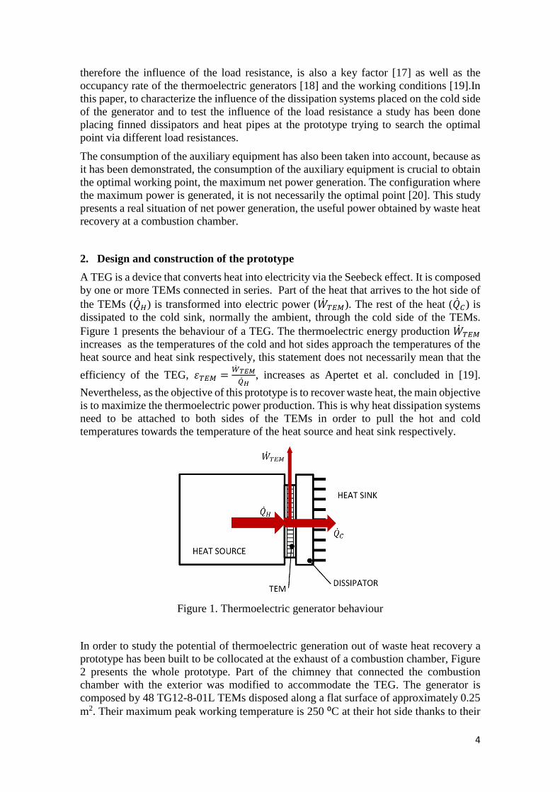
A TEG is a device that converts heat into electricity via the Seebeck effect. It is composed by one or more TEMs connected in series. Part of the heat that arrives to the hot side of the TEMs (���) is transformed into electric power (+� �). The rest of the heat (���) is dissipated to the cold sink, normally the ambient, through the cold side of the TEMs. Figure 1 presents the behaviour of a TEG. The thermoelectric energy production +� � increases as the temperatures of the cold and hot sides approach the temperatures of the heat source and heat sink respectively, this statement does not necessarily mean that the
efficiency of the TEG, �� = -� ./01�2 , increases as Apertet et al. concluded in [19].
Nevertheless, as the objective of this prototype is to recover waste heat, the main objective is to maximize the thermoelectric power production. This is why heat dissipation systems need to be attached to both sides of the TEMs in order to pull the hot and cold temperatures towards the temperature of the heat source and heat sink respectively.
Figure 1. Thermoelectric generator behaviour
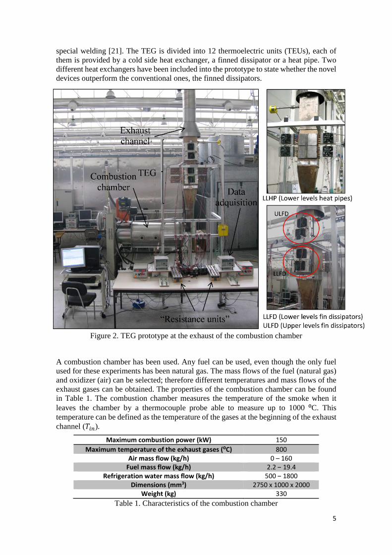
In order to study the potential of thermoelectric generation out of waste heat recovery a prototype has been built to be collocated at the exhaust of a combustion chamber, Figure 2 presents the whole prototype. Part of the chimney that connected the combustion chamber with the exterior was modified to accommodate the TEG. The generator is composed by 48 TG12-8-01L TEMs disposed along a flat surface of approximately 0.25 m2. Their maximum peak working temperature is 250 ⁰C at their hot side thanks to their
5
special welding [21]. The TEG is divided into 12 thermoelectric units (TEUs), each of them is provided by a cold side heat exchanger, a finned dissipator or a heat pipe. Two different heat exchangers have been included into the prototype to state whether the novel devices outperform the conventional ones, the finned dissipators.
Figure 2. TEG prototype at the exhaust of the combustion chamber
A combustion chamber has been used. Any fuel can be used, even though the only fuel used for these experiments has been natural gas. The mass flows of the fuel (natural gas) and oxidizer (air) can be selected; therefore different temperatures and mass flows of the exhaust gases can be obtained. The properties of the combustion chamber can be found in Table 1. The combustion chamber measures the temperature of the smoke when it leaves the chamber by a thermocouple probe able to measure up to 1000 ⁰C. This temperature can be defined as the temperature of the gases at the beginning of the exhaust channel ($"�).
Maximum combustion power (kW) 150
Maximum temperature of the exhaust gases (⁰C) 800
Air mass flow (kg/h) 0 – 160
Fuel mass flow (kg/h) 2.2 – 19.4
Refrigeration water mass flow (kg/h) 500 – 1800
Dimensions (mm3) 2750 x 1000 x 2000
Weight (kg) 330
Table 1. Characteristics of the combustion chamber
6
The chimney was accommodated to house the TEG. The cylindrical shape was transformed to a 0.26 x 0.26 m2 quadrangular section. The square chimney has a nozzle on one end to connect the TEG with the previous round-shape chimney. The interior and exterior walls are flat. In the inside of the chimney the exhaust gases circulate transferring their heat to the flat wall while on the exterior surface the TEMs that form the TEG prototype are placed. Once the smoke has feed the TEG, it is collected and conducted to the exterior by the original chimney. The material of the whole chimney is stainless steel.
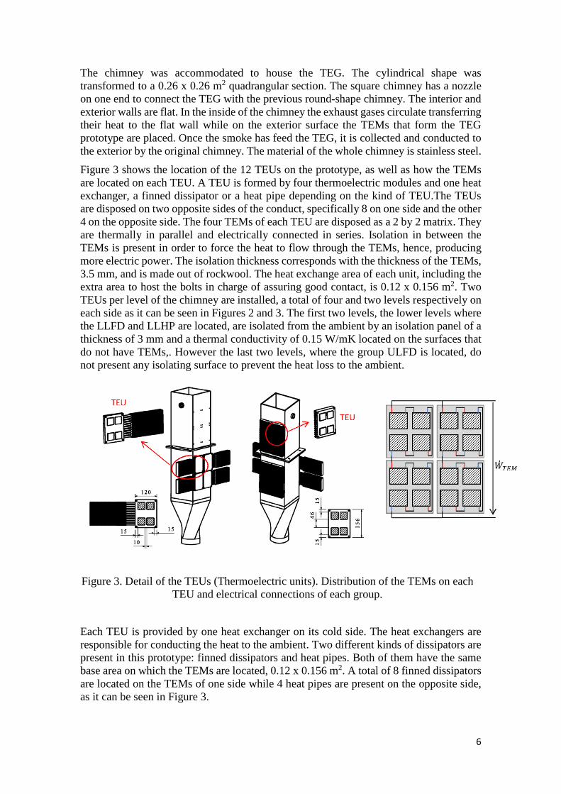
Figure 3 shows the location of the 12 TEUs on the prototype, as well as how the TEMs are located on each TEU. A TEU is formed by four thermoelectric modules and one heat exchanger, a finned dissipator or a heat pipe depending on the kind of TEU.The TEUs are disposed on two opposite sides of the conduct, specifically 8 on one side and the other 4 on the opposite side. The four TEMs of each TEU are disposed as a 2 by 2 matrix. They are thermally in parallel and electrically connected in series. Isolation in between the TEMs is present in order to force the heat to flow through the TEMs, hence, producing more electric power. The isolation thickness corresponds with the thickness of the TEMs, 3.5 mm, and is made out of rockwool. The heat exchange area of each unit, including the extra area to host the bolts in charge of assuring good contact, is 0.12 x 0.156 m2. Two TEUs per level of the chimney are installed, a total of four and two levels respectively on each side as it can be seen in Figures 2 and 3. The first two levels, the lower levels where the LLFD and LLHP are located, are isolated from the ambient by an isolation panel of a thickness of 3 mm and a thermal conductivity of 0.15 W/mK located on the surfaces that do not have TEMs,. However the last two levels, where the group ULFD is located, do not present any isolating surface to prevent the heat loss to the ambient.
Figure 3. Detail of the TEUs (Thermoelectric units). Distribution of the TEMs on each TEU and electrical connections of each group.
Each TEU is provided by one heat exchanger on its cold side. The heat exchangers are responsible for conducting the heat to the ambient. Two different kinds of dissipators are present in this prototype: finned dissipators and heat pipes. Both of them have the same base area on which the TEMs are located, 0.12 x 0.156 m2. A total of 8 finned dissipators are located on the TEMs of one side while 4 heat pipes are present on the opposite side, as it can be seen in Figure 3.
7
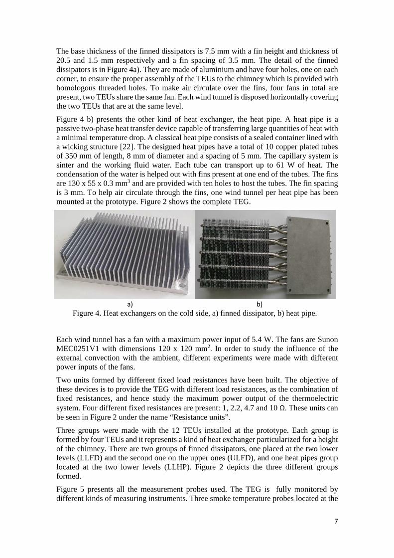
The base thickness of the finned dissipators is 7.5 mm with a fin height and thickness of 20.5 and 1.5 mm respectively and a fin spacing of 3.5 mm. The detail of the finned dissipators is in Figure 4a). They are made of aluminium and have four holes, one on each corner, to ensure the proper assembly of the TEUs to the chimney which is provided with homologous threaded holes. To make air circulate over the fins, four fans in total are present, two TEUs share the same fan. Each wind tunnel is disposed horizontally covering the two TEUs that are at the same level.
Figure 4 b) presents the other kind of heat exchanger, the heat pipe. A heat pipe is a passive two-phase heat transfer device capable of transferring large quantities of heat with a minimal temperature drop. A classical heat pipe consists of a sealed container lined with a wicking structure [22]. The designed heat pipes have a total of 10 copper plated tubes of 350 mm of length, 8 mm of diameter and a spacing of 5 mm. The capillary system is sinter and the working fluid water. Each tube can transport up to 61 W of heat. The condensation of the water is helped out with fins present at one end of the tubes. The fins are 130 x 55 x 0.3 mm3 and are provided with ten holes to host the tubes. The fin spacing is 3 mm. To help air circulate through the fins, one wind tunnel per heat pipe has been mounted at the prototype. Figure 2 shows the complete TEG.
a) b)
Figure 4. Heat exchangers on the cold side, a) finned dissipator, b) heat pipe.
Each wind tunnel has a fan with a maximum power input of 5.4 W. The fans are Sunon MEC0251V1 with dimensions 120 x 120 mm2. In order to study the influence of the external convection with the ambient, different experiments were made with different power inputs of the fans.
Two units formed by different fixed load resistances have been built. The objective of these devices is to provide the TEG with different load resistances, as the combination of fixed resistances, and hence study the maximum power output of the thermoelectric system. Four different fixed resistances are present: 1, 2.2, 4.7 and 10 Ω. These units can be seen in Figure 2 under the name “Resistance units”.
Three groups were made with the 12 TEUs installed at the prototype. Each group is formed by four TEUs and it represents a kind of heat exchanger particularized for a height of the chimney. There are two groups of finned dissipators, one placed at the two lower levels (LLFD) and the second one on the upper ones (ULFD), and one heat pipes group located at the two lower levels (LLHP). Figure 2 depicts the three different groups formed.
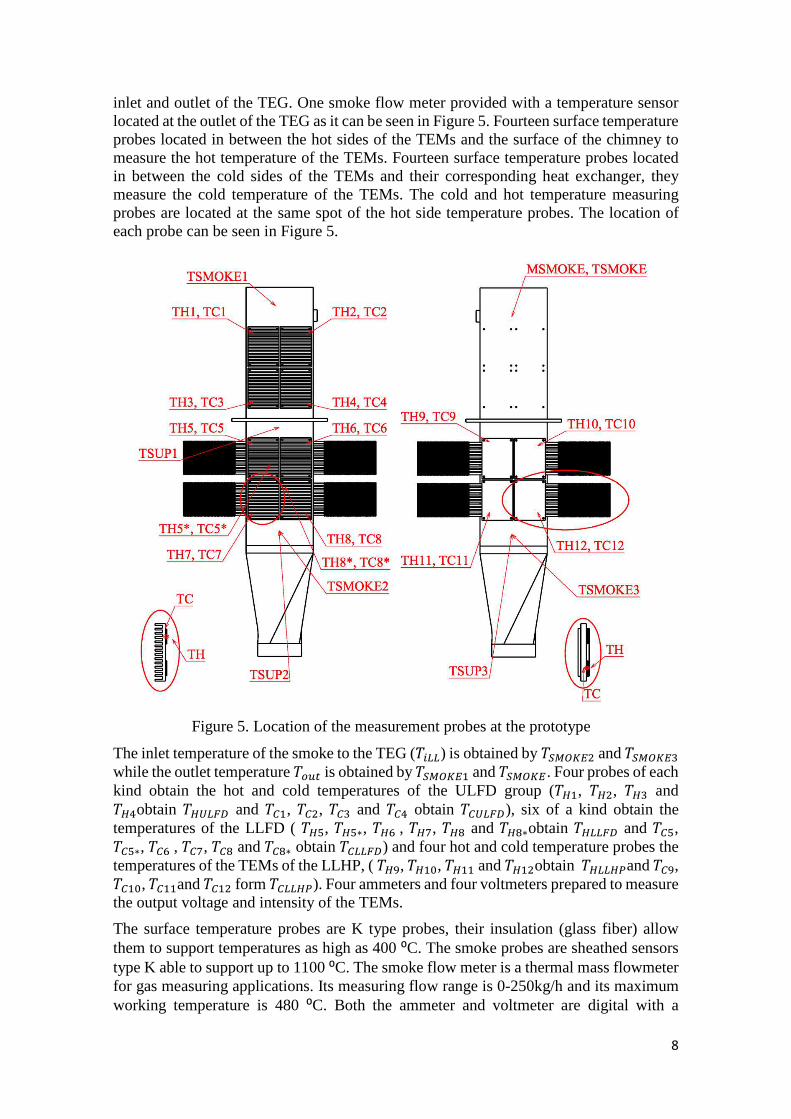
Figure 5 presents all the measurement probes used. The TEG is fully monitored by different kinds of measuring instruments. Three smoke temperature probes located at the
8
inlet and outlet of the TEG. One smoke flow meter provided with a temperature sensor located at the outlet of the TEG as it can be seen in Figure 5. Fourteen surface temperature probes located in between the hot sides of the TEMs and the surface of the chimney to measure the hot temperature of the TEMs. Fourteen surface temperature probes located in between the cold sides of the TEMs and their corresponding heat exchanger, they measure the cold temperature of the TEMs. The cold and hot temperature measuring probes are located at the same spot of the hot side temperature probes. The location of each probe can be seen in Figure 5.
Figure 5. Location of the measurement probes at the prototype
The inlet temperature of the smoke to the TEG ($"##) is obtained by $3456 and $3457 while the outlet temperature $ �� is obtained by $3458 and $345. Four probes of each kind obtain the hot and cold temperatures of the ULFD group ($�8, $�6, $�7 and $�9obtain $�(#%& and $�8, $�6, $�7 and $�9 obtain $�(#%&), six of a kind obtain the temperatures of the LLFD ( $�:, $�:∗, $�<, $�>, $�? and $�?∗obtain $�##%& and $�:, $�:∗, $�<, $�>, $�? and $�?∗ obtain $�##%&) and four hot and cold temperature probes the temperatures of the TEMs of the LLHP, ( $�@, $�8A, $�88 and $�86obtain $�##�'and $�@, $�8A, $�88and $�86 form $�##�'). Four ammeters and four voltmeters prepared to measure the output voltage and intensity of the TEMs.
The surface temperature probes are K type probes, their insulation (glass fiber) allow them to support temperatures as high as 400 ⁰C. The smoke probes are sheathed sensors type K able to support up to 1100 ⁰C. The smoke flow meter is a thermal mass flowmeter for gas measuring applications. Its measuring flow range is 0-250kg/h and its maximum working temperature is 480 ⁰C. Both the ammeter and voltmeter are digital with a
9
sampling rate of 1kHz and a resolution of 12 bits (±2048 digits). In Table 2 the resolution and the accuracy of all the measurement instruments can be found.
3. Experimentation methodology
Different variables were modified to obtain a complete study on the influence of the parameters over the thermoelectric power generation as well as over the net generation.
The net power generation corresponds with the generation power minus the consumption of the auxiliary equipment, the goal to maximize. It has been demonstrated that the power consumption of the auxiliary equipment is necessary to take into account to optimize a TEG [20]. The maximum generated power working point did not correspond with the maximum net power generation working point.
+� ��� = +� � −+���� (1)
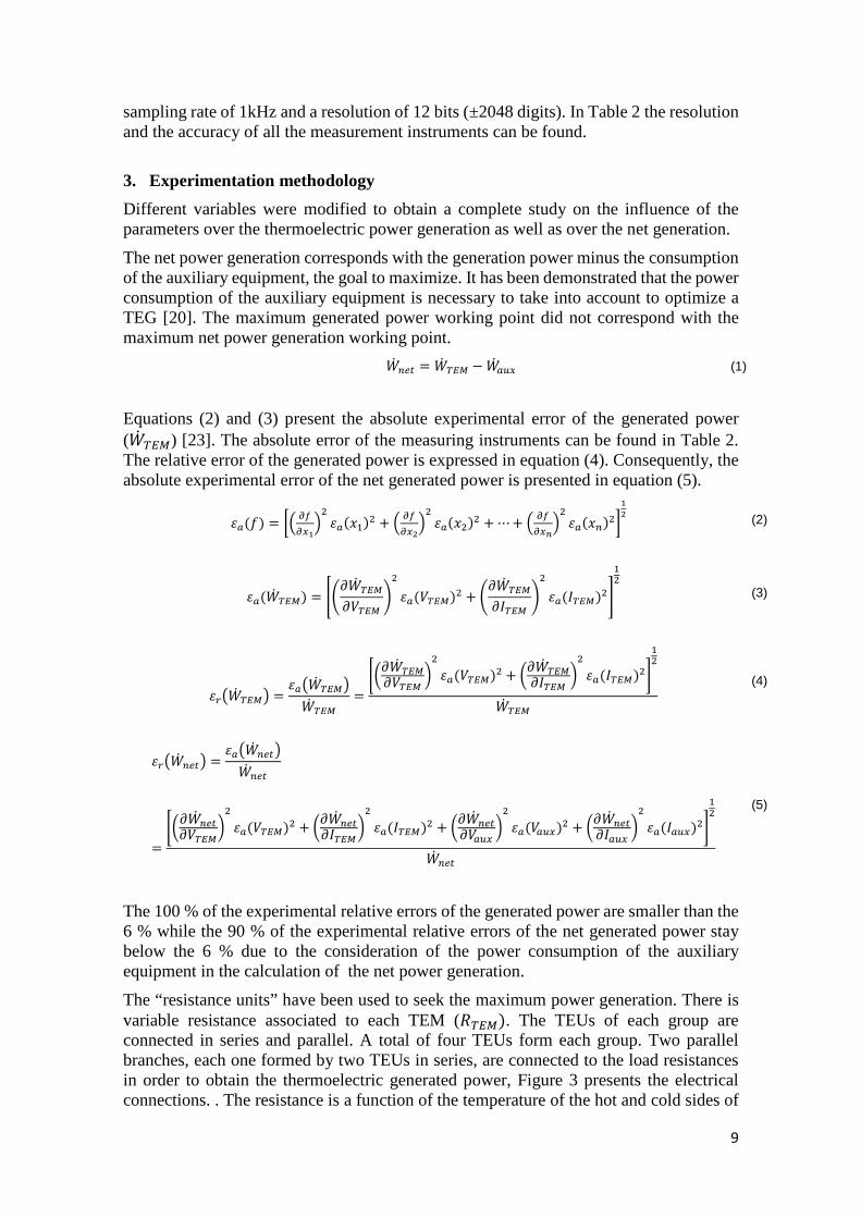
Equations (2) and (3) present the absolute experimental error of the generated power (+� �) [23]. The absolute error of the measuring instruments can be found in Table 2. The relative error of the generated power is expressed in equation (4). Consequently, the absolute experimental error of the net generated power is presented in equation (5).
��(D) = FG HIH�JK6 ��(L8)6 + G HIH�NK6 ��(L6)6 +⋯+ G HIH�PK6 ��(L�)6QJN (2)
��(+� �) = RST+� �T*� U6 ��(*�)6 + ST+� �T�� U6 ��(��)6V86 (3)
��W+� �X = ��W+� �X+� � = YZT+� �T*� [6 ��(*�)6 + ZT+� �T�� [6 ��(��)6\86
+� � (4)
��W+� ���X = ��W+� ���X+� ���
= YZT+� ���T*�[6 ��(*�)6 + ZT+� ���T��[6 ��(��)6 + ZT+� ���T*��� [
6 ��(*���)6 + ZT+� ���T���� [6 ��(����)6\
86+� ���
(5)
The 100 % of the experimental relative errors of the generated power are smaller than the 6 % while the 90 % of the experimental relative errors of the net generated power stay below the 6 % due to the consideration of the power consumption of the auxiliary equipment in the calculation of the net power generation.
The “resistance units” have been used to seek the maximum power generation. There is variable resistance associated to each TEM (��). The TEUs of each group are connected in series and parallel. A total of four TEUs form each group. Two parallel branches, each one formed by two TEUs in series, are connected to the load resistances in order to obtain the thermoelectric generated power, Figure 3 presents the electrical connections. . The resistance is a function of the temperature of the hot and cold sides of
10
the TEM. The load resistance (�#) that maximizes the power generation is the one that equals the interior resistance of the TEM at the working point [24], so that, it is necessary to modify the load resistance in order to find the maximum power generation. Varying the load resistance Figures 7 to 10 can be obtained, showing the influence of the load resistance over the thermoelectric generated power. The load resistance values have been selected taking into account how the TEUs are electrically connected inside each group, see Figure 3, so that the optimum in generation can be achieved.
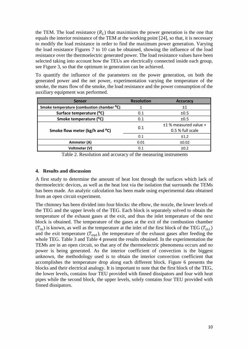
To quantify the influence of the parameters on the power generation, on both the generated power and the net power, experimentation varying the temperature of the smoke, the mass flow of the smoke, the load resistance and the power consumption of the auxiliary equipment was performed.
Sensor Resolution Accuracy
Smoke temperature (combustion chamber ⁰C) 1 ±1
Surface temperature (⁰C) 0.1 ±0.5
Smoke temperature (⁰C) 0.1 ±0.5
Smoke flow meter (kg/h and ⁰C) 0.1
±1 % measured value +
0.5 % full scale
0.1 ±1.2
Ammeter (A) 0.01 ±0.02
Voltmeter (V) 0.1 ±0.2
Table 2. Resolution and accuracy of the measuring instruments
4. Results and discussion
A first study to determine the amount of heat lost through the surfaces which lack of thermoelectric devices, as well as the heat lost via the isolation that surrounds the TEMs has been made. An analytic calculation has been made using experimental data obtained from an open circuit experiment.
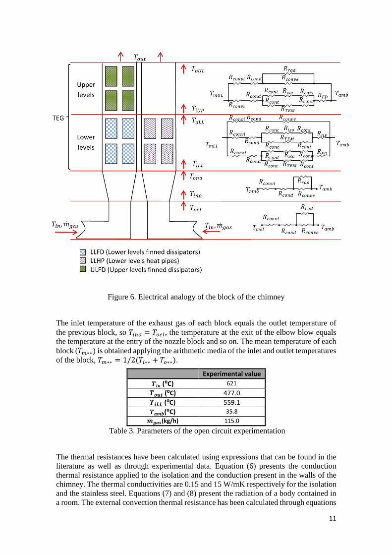
The chimney has been divided into four blocks: the elbow, the nozzle, the lower levels of the TEG and the upper levels of the TEG. Each block is separately solved to obtain the temperature of the exhaust gases at the exit, and thus the inlet temperature of the next block is obtained. The temperature of the gases at the exit of the combustion chamber ($"�) is known, as well as the temperature at the inlet of the first block of the TEG ($"##) and the exit temperature ($ ��), the temperature of the exhaust gases after feeding the whole TEG. Table 3 and Table 4 present the results obtained. In the experimentation the TEMs are in an open circuit, so that any of the thermoelectric phenomena occurs and no power is being generated. As the interior coefficient of convection is the biggest unknown, the methodology used is to obtain the interior convection coefficient that accomplishes the temperature drop along each different block. Figure 6 presents the blocks and their electrical analogy. It is important to note that the first block of the TEG, the lower levels, contains four TEU provided with finned dissipators and four with heat pipes while the second block, the upper levels, solely contains four TEU provided with finned dissipators.
11
Figure 6. Electrical analogy of the block of the chimney
The inlet temperature of the exhaust gas of each block equals the outlet temperature of the previous block, so $"� = $ ��, the temperature at the exit of the elbow blow equals the temperature at the entry of the nozzle block and so on. The mean temperature of each block ($)∗∗) is obtained applying the arithmetic media of the inlet and outlet temperatures of the block, $)∗∗ = 1/2($"∗∗ + $ ∗∗).
Experimental value `ab (⁰C) 621 `cde (⁰C) 477.0 `aff (⁰C) 559.1 `ghi(⁰C) 35.8 h� jgk(kg/h) 115.0
Table 3. Parameters of the open circuit experimentation
The thermal resistances have been calculated using expressions that can be found in the literature as well as through experimental data. Equation (6) presents the conduction thermal resistance applied to the isolation and the conduction present in the walls of the chimney. The thermal conductivities are 0.15 and 15 W/mK respectively for the isolation and the stainless steel. Equations (7) and (8) present the radiation of a body contained in a room. The external convection thermal resistance has been calculated through equations
12
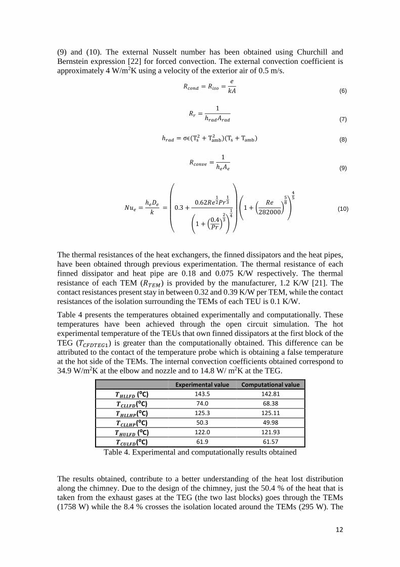
(9) and (10). The external Nusselt number has been obtained using Churchill and Bernstein expression [22] for forced convection. The external convection coefficient is approximately 4 W/m2K using a velocity of the exterior air of 0.5 m/s.
� �� = �"� = l��
(6)
�� = 1ℎ�������
(7)
ℎ��� = σϵ(Tn6 + Topq6 )(Tn + Topq) (8)
� �!� = 1ℎ���
(9)
rs� = ℎ�t�� =uvvvw0.3 + 0.62�l86|}87
~1 + G0.4|}K67�
89������1 + Z �l282000[
:?�9: (10)
The thermal resistances of the heat exchangers, the finned dissipators and the heat pipes, have been obtained through previous experimentation. The thermal resistance of each finned dissipator and heat pipe are 0.18 and 0.075 K/W respectively. The thermal resistance of each TEM (��) is provided by the manufacturer, 1.2 K/W [21]. The contact resistances present stay in between 0.32 and 0.39 K/W per TEM, while the contact resistances of the isolation surrounding the TEMs of each TEU is 0.1 K/W.
Table 4 presents the temperatures obtained experimentally and computationally. These temperatures have been achieved through the open circuit simulation. The hot experimental temperature of the TEUs that own finned dissipators at the first block of the TEG ($�%&��8) is greater than the computationally obtained. This difference can be attributed to the contact of the temperature probe which is obtaining a false temperature at the hot side of the TEMs. The internal convection coefficients obtained correspond to 34.9 W/m2K at the elbow and nozzle and to 14.8 W/ m2K at the TEG.
Experimental value Computational value `�ff�� (⁰C) 143.5 142.81 `�ff��(⁰C) 74.0 68.38 `�ff��(⁰C) 125.3 125.11 `�ff��(⁰C) 50.3 49.98 `��f�� (⁰C) 122.0 121.93 `��f��(⁰C) 61.9 61.57
Table 4. Experimental and computationally results obtained
The results obtained, contribute to a better understanding of the heat lost distribution along the chimney. Due to the design of the chimney, just the 50.4 % of the heat that is taken from the exhaust gases at the TEG (the two last blocks) goes through the TEMs (1758 W) while the 8.4 % crosses the isolation located around the TEMs (295 W). The
13
rest, the 41.2 % is lost via the free surfaces as convection or a combination of convection and radiation (1438.6 W). The first block of the TEG is totally isolated from the ambient with 3 mm thickness rockwool, while the second one is not. Before the smoke arrives to the TEG an important heat lost exists, the heat that is transferred to the ambient via the surfaces of the elbow and the nozzle. It corresponds to the 45 % of the heat loss of the exhaust gases (2849.1 W), while the other 55 % is lost to the ambient at the TEG itself (3492 W). Figure 6 presents the electrical analogy of the whole chimney.
Different studies varying the parameters of operation have been developed, the temperature of the exhaust gas, its mass flow and the power consumption of the auxiliary equipment have focused the attention.
4.1. Influence of the mass flow of the exhaust gas
Three different mass flows were tested, 67, 84 and 118 kg/h. These values were obtained modifying the mass flows of the natural gas and the air introduced into the combustion chamber. The temperature was maintained constant along the whole experimentation; the exhaust gases left the combustion chamber at 591 ⁰C. To test the influence of the consumption of the fans over the thermoelectric generation, two power consumptions per TEU were tested 1.11 and 5.40 W. Table 5 presents the details of the experimentation.
`ab (⁰C) Mass flow (kg/h) `ab`�� (⁰C) `cde (⁰C)
591
67.0 504.5 428.4
83.7 514.2 450.6
118.2 528.7 472.8
525
67.0
459.8 405.7
560 476.8 407.0
591 504.5 428.4
Table 5. Temperatures and mass flows of the experiments conducted
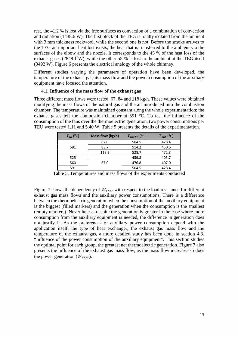
Figure 7 shows the dependency of +� � with respect to the load resistance for different exhaust gas mass flows and the auxiliary power consumptions. There is a difference between the thermoelectric generation when the consumption of the auxiliary equipment is the biggest (filled markers) and the generation when the consumption is the smallest (empty markers). Nevertheless, despite the generation is greater in the case where more consumption from the auxiliary equipment is needed, the difference in generation does not justify it. As the preferences of auxiliary power consumption depend with the application itself: the type of heat exchanger, the exhaust gas mass flow and the temperature of the exhaust gas, a more detailed study has been done in section 4.3. “Influence of the power consumption of the auxiliary equipment”. This section studies the optimal point for each group, the greatest net thermoelectric generation. Figure 7 also presents the influence of the exhaust gas mass flow, as the mass flow increases so does the power generation (+� �).
14
Figure 7. +� � of the whole TEG dependence with respect to the load resistance for
different exhaust gas mass flows and two auxiliary power consumptions. The temperature of the exhaust gas is 591 ⁰C. The load resistance is referred to each group.
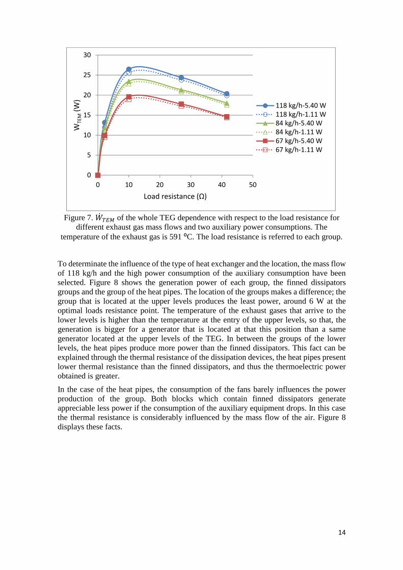
To determinate the influence of the type of heat exchanger and the location, the mass flow of 118 kg/h and the high power consumption of the auxiliary consumption have been selected. Figure 8 shows the generation power of each group, the finned dissipators groups and the group of the heat pipes. The location of the groups makes a difference; the group that is located at the upper levels produces the least power, around 6 W at the optimal loads resistance point. The temperature of the exhaust gases that arrive to the lower levels is higher than the temperature at the entry of the upper levels, so that, the generation is bigger for a generator that is located at that this position than a same generator located at the upper levels of the TEG. In between the groups of the lower levels, the heat pipes produce more power than the finned dissipators. This fact can be explained through the thermal resistance of the dissipation devices, the heat pipes present lower thermal resistance than the finned dissipators, and thus the thermoelectric power obtained is greater.
In the case of the heat pipes, the consumption of the fans barely influences the power production of the group. Both blocks which contain finned dissipators generate appreciable less power if the consumption of the auxiliary equipment drops. In this case the thermal resistance is considerably influenced by the mass flow of the air. Figure 8 displays these facts.
0
5
10
15
20
25
30
0 10 20 30 40 50
WT
EM
(W)
Load resistance (Ω)
118 kg/h-5.40 W
118 kg/h-1.11 W
84 kg/h-5.40 W
84 kg/h-1.11 W
67 kg/h-5.40 W
67 kg/h-1.11 W
15
Figure 8. +� � of the three groups as a function of the load resistance for a gas mass
flow and temperature of 118 kg/h and 591 ⁰C respectively. Two auxiliary power consumptions, 5.40 and 1.11 W are present. The load resistance is for to each group.
4.2. Influence of the temperature of the exhaust gas
The influence of the temperature of the exhaust gas has been studied through the comparison of experiments using three temperatures of the exhaust gas ($"�). The three temperatures correspond with 525, 560 and 591 ⁰C. The mass flow of the exhaust gas is 67 kg/h. The fan consumption corresponds to the lower level, 1.11 W per TEU (LP).
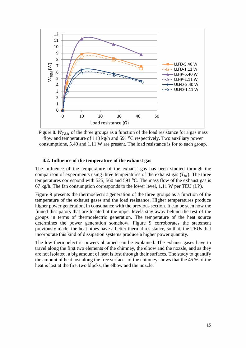
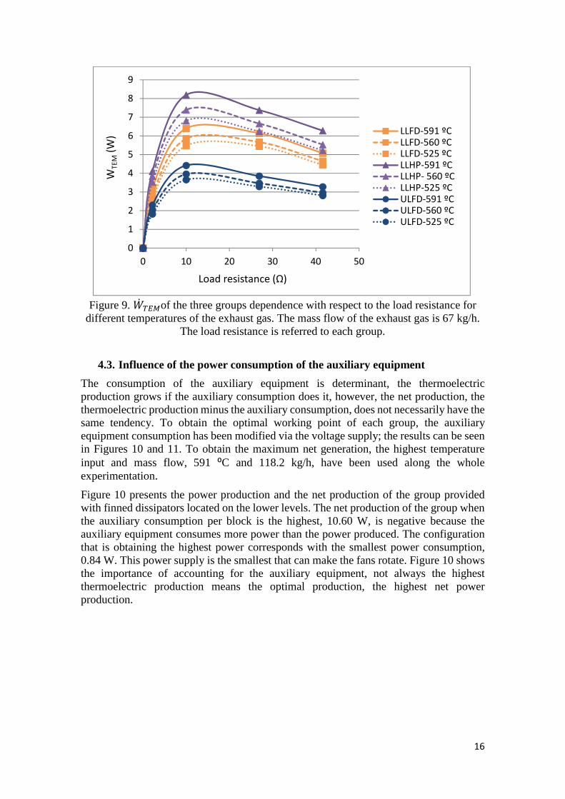
Figure 9 presents the thermoelectric generation of the three groups as a function of the temperature of the exhaust gases and the load resistance. Higher temperatures produce higher power generation, in consonance with the previous section. It can be seen how the finned dissipators that are located at the upper levels stay away behind the rest of the groups in terms of thermoelectric generation. The temperature of the heat source determines the power generation somehow. Figure 9 corroborates the statement previously made, the heat pipes have a better thermal resistance, so that, the TEUs that incorporate this kind of dissipation systems produce a higher power quantity.
The low thermoelectric powers obtained can be explained. The exhaust gases have to travel along the first two elements of the chimney, the elbow and the nozzle, and as they are not isolated, a big amount of heat is lost through their surfaces. The study to quantify the amount of heat lost along the free surfaces of the chimney shows that the 45 % of the heat is lost at the first two blocks, the elbow and the nozzle.
0
1
2
3
4
5
6
7
8
9
10
11
12
0 10 20 30 40 50
WT
EM
(W)
Load resistance (Ω)
LLFD-5.40 WLLFD-1.11 WLLHP-5.40 WLLHP-1.11 WULFD-5.40 WULFD-1.11 W
16
Figure 9. +� �of the three groups dependence with respect to the load resistance for
different temperatures of the exhaust gas. The mass flow of the exhaust gas is 67 kg/h. The load resistance is referred to each group.
4.3. Influence of the power consumption of the auxiliary equipment
The consumption of the auxiliary equipment is determinant, the thermoelectric production grows if the auxiliary consumption does it, however, the net production, the thermoelectric production minus the auxiliary consumption, does not necessarily have the same tendency. To obtain the optimal working point of each group, the auxiliary equipment consumption has been modified via the voltage supply; the results can be seen in Figures 10 and 11. To obtain the maximum net generation, the highest temperature input and mass flow, 591 ⁰C and 118.2 kg/h, have been used along the whole experimentation.
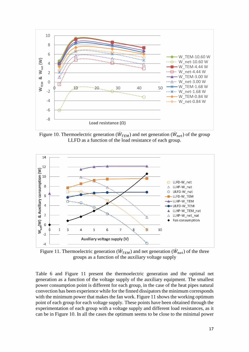
Figure 10 presents the power production and the net production of the group provided with finned dissipators located on the lower levels. The net production of the group when the auxiliary consumption per block is the highest, 10.60 W, is negative because the auxiliary equipment consumes more power than the power produced. The configuration that is obtaining the highest power corresponds with the smallest power consumption, 0.84 W. This power supply is the smallest that can make the fans rotate. Figure 10 shows the importance of accounting for the auxiliary equipment, not always the highest thermoelectric production means the optimal production, the highest net power production.
0
1
2
3
4
5
6
7
8
9
0 10 20 30 40 50
WT
EM
(W)
Load resistance (Ω)
LLFD-591 ºCLLFD-560 ºCLLFD-525 ºCLLHP-591 ºCLLHP- 560 ºCLLHP-525 ºCULFD-591 ºCULFD-560 ºCULFD-525 ºC
17
Figure 10. Thermoelectric generation (+� �) and net generation (+� ���) of the group
LLFD as a function of the load resistance of each group.
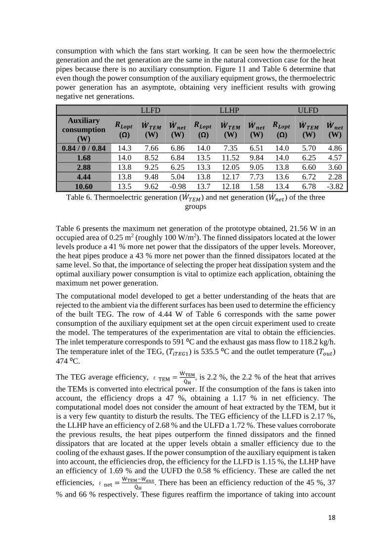
Figure 11. Thermoelectric generation (+� �) and net generation (+� ���) of the three
groups as a function of the auxiliary voltage supply
Table 6 and Figure 11 present the thermoelectric generation and the optimal net generation as a function of the voltage supply of the auxiliary equipment. The smallest power consumption point is different for each group, in the case of the heat pipes natural convection has been experience while for the finned dissipators the minimum corresponds with the minimum power that makes the fan work. Figure 11 shows the working optimum point of each group for each voltage supply. These points have been obtained through the experimentation of each group with a voltage supply and different load resistances, as it can be in Figure 10. In all the cases the optimum seems to be close to the minimal power
-8
-6
-4
-2
0
2
4
6
8
10
0 10 20 30 40 50
WT
EM
& W
ne
t(W
)
Load resistance (Ω)
W_TEM-10.60 WW_net-10.60 WW_TEM-4.44 WW_net-4.44 WW_TEM-3.00 WW_net-3.00 WW_TEM-1.68 WW_net-1.68 WW_TEM-0.84 WW_net-0.84 W
18
consumption with which the fans start working. It can be seen how the thermoelectric generation and the net generation are the same in the natural convection case for the heat pipes because there is no auxiliary consumption. Figure 11 and Table 6 determine that even though the power consumption of the auxiliary equipment grows, the thermoelectric power generation has an asymptote, obtaining very inefficient results with growing negative net generations.
LLFD LLHP ULFD Auxiliary
consumption (W)
�fc�e(Ω)
�� `�� (W)
�� b�e (W)
�fc�e (Ω)
�� `�� (W)
�� b�e (W)
�fc�e (Ω)
�� `�� (W)
�� b�e (W)
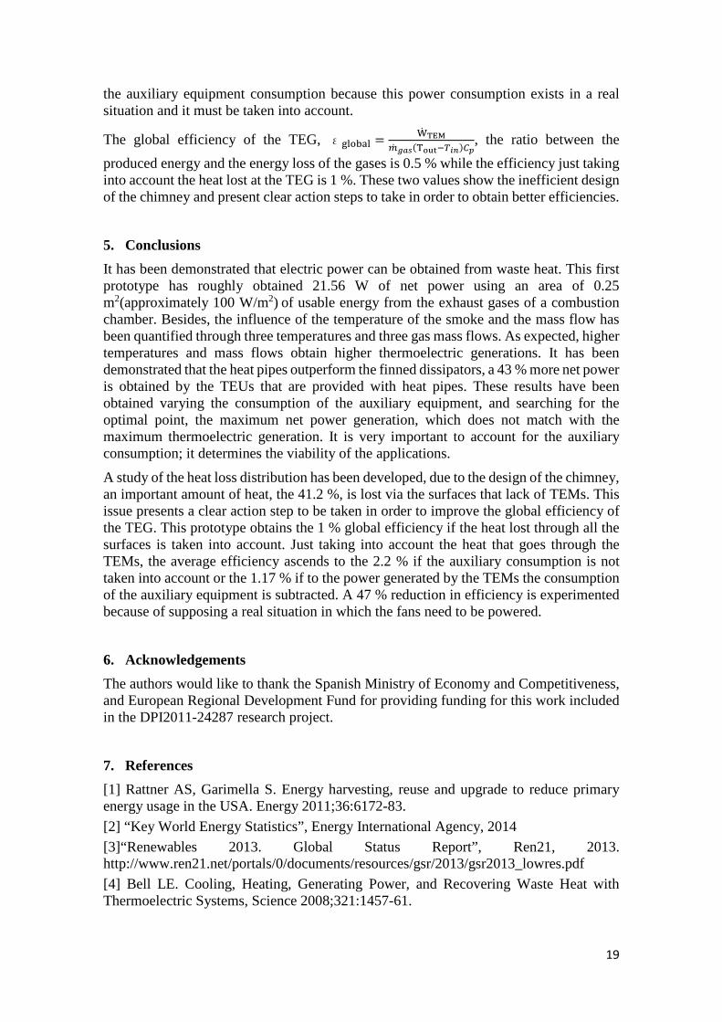
0.84 / 0 / 0.84 14.3 7.66 6.86 14.0 7.35 6.51 14.0 5.70 4.86 1.68 14.0 8.52 6.84 13.5 11.52 9.84 14.0 6.25 4.57 2.88 13.8 9.25 6.25 13.3 12.05 9.05 13.8 6.60 3.60 4.44 13.8 9.48 5.04 13.8 12.17 7.73 13.6 6.72 2.28 10.60 13.5 9.62 -0.98 13.7 12.18 1.58 13.4 6.78 -3.82
Table 6. Thermoelectric generation (+� �) and net generation (+� ���) of the three groups
Table 6 presents the maximum net generation of the prototype obtained, 21.56 W in an occupied area of 0.25 m2 (roughly 100 W/m2). The finned dissipators located at the lower levels produce a 41 % more net power that the dissipators of the upper levels. Moreover, the heat pipes produce a 43 % more net power than the finned dissipators located at the same level. So that, the importance of selecting the proper heat dissipation system and the optimal auxiliary power consumption is vital to optimize each application, obtaining the maximum net power generation.
The computational model developed to get a better understanding of the heats that are rejected to the ambient via the different surfaces has been used to determine the efficiency of the built TEG. The row of 4.44 W of Table 6 corresponds with the same power consumption of the auxiliary equipment set at the open circuit experiment used to create the model. The temperatures of the experimentation are vital to obtain the efficiencies. The inlet temperature corresponds to 591 ⁰C and the exhaust gas mass flow to 118.2 kg/h. The temperature inlet of the TEG, ($"��8) is 535.5 ⁰C and the outlet temperature ($ ��) 474 ⁰C.
The TEG average efficiency, �� = �� ����� � , is 2.2 %, the 2.2 % of the heat that arrives
the TEMs is converted into electrical power. If the consumption of the fans is taken into account, the efficiency drops a 47 %, obtaining a 1.17 % in net efficiency. The computational model does not consider the amount of heat extracted by the TEM, but it is a very few quantity to disturb the results. The TEG efficiency of the LLFD is 2.17 %, the LLHP have an efficiency of 2.68 % and the ULFD a 1.72 %. These values corroborate the previous results, the heat pipes outperform the finned dissipators and the finned dissipators that are located at the upper levels obtain a smaller efficiency due to the cooling of the exhaust gases. If the power consumption of the auxiliary equipment is taken into account, the efficiencies drop, the efficiency for the LLFD is 1.15 %, the LLHP have an efficiency of 1.69 % and the UUFD the 0.58 % efficiency. These are called the net
efficiencies, ε�� = �� ���¡-� ¢£¤�� � . There has been an efficiency reduction of the 45 %, 37
% and 66 % respectively. These figures reaffirm the importance of taking into account
19
the auxiliary equipment consumption because this power consumption exists in a real situation and it must be taken into account.
The global efficiency of the TEG, 奦§qo¦ = �� ���)� ¨¢©(�ª«¬¡�P)�®, the ratio between the
produced energy and the energy loss of the gases is 0.5 % while the efficiency just taking into account the heat lost at the TEG is 1 %. These two values show the inefficient design of the chimney and present clear action steps to take in order to obtain better efficiencies.
5. Conclusions
It has been demonstrated that electric power can be obtained from waste heat. This first prototype has roughly obtained 21.56 W of net power using an area of 0.25 m2(approximately 100 W/m2) of usable energy from the exhaust gases of a combustion chamber. Besides, the influence of the temperature of the smoke and the mass flow has been quantified through three temperatures and three gas mass flows. As expected, higher temperatures and mass flows obtain higher thermoelectric generations. It has been demonstrated that the heat pipes outperform the finned dissipators, a 43 % more net power is obtained by the TEUs that are provided with heat pipes. These results have been obtained varying the consumption of the auxiliary equipment, and searching for the optimal point, the maximum net power generation, which does not match with the maximum thermoelectric generation. It is very important to account for the auxiliary consumption; it determines the viability of the applications.
A study of the heat loss distribution has been developed, due to the design of the chimney, an important amount of heat, the 41.2 %, is lost via the surfaces that lack of TEMs. This issue presents a clear action step to be taken in order to improve the global efficiency of the TEG. This prototype obtains the 1 % global efficiency if the heat lost through all the surfaces is taken into account. Just taking into account the heat that goes through the TEMs, the average efficiency ascends to the 2.2 % if the auxiliary consumption is not taken into account or the 1.17 % if to the power generated by the TEMs the consumption of the auxiliary equipment is subtracted. A 47 % reduction in efficiency is experimented because of supposing a real situation in which the fans need to be powered.
6. Acknowledgements
The authors would like to thank the Spanish Ministry of Economy and Competitiveness, and European Regional Development Fund for providing funding for this work included in the DPI2011-24287 research project.
7. References
[1] Rattner AS, Garimella S. Energy harvesting, reuse and upgrade to reduce primary energy usage in the USA. Energy 2011;36:6172-83.
[2] “Key World Energy Statistics”, Energy International Agency, 2014
[3]“Renewables 2013. Global Status Report”, Ren21, 2013. http://www.ren21.net/portals/0/documents/resources/gsr/2013/gsr2013_lowres.pdf
[4] Bell LE. Cooling, Heating, Generating Power, and Recovering Waste Heat with Thermoelectric Systems, Science 2008;321:1457-61.
20
[5] Yodovard P, Khedar J, Hirunlabh J. The potential of waste heat thermoelectric power generation from diesel cycle and gas turbine cogeneration plants. Energ Source 2001;23 (3): 213-24.
[6] Rowe DM. Thermoelectrics Handbook. Macro to Nano. 1st ed. Boca Raton (FL): CRC Press; 2006.
[7] LeGrandeur J, Crane D, Eder A, Vehicle fuel economy improvement through thermoelectric waste heat recovery. DEER Conference, Chicago (IL) 2005.
[8] Montecucco A, Knox AR. Accurate simulation of thermoelectric power generating systems. Appl Energ 2014;118:166-72.
[9] Lee H. Optimal design of thermoelectric devices with dimensional analysis. Appl Energ 2013;106:79-88.
[10] Massaguer E, Massaguer A, Montoro L, Gonzalez JR. Development and validation of a new TRNSYS type for the simulation of thermoelectric generators. Appl Energ 2014;134: 65-74.
[11] Astrain D, Vián JG, Martínez A, Rodríguez, A. Study of the influence of heat exchangers’ thermal resistances on a thermoelectric generation system. Energy 2010;39:602-10.
[12] Rowe DM. Thermoelectrics, and environmentally-friendly source of electrical power. Renew Energ 1999;16(1-4):1251-6.
[13] Jang JY, Tsai YC, Wu CW. A study of 3-D numerical simulation and comparison with experimental results on turbulent flow of venting flue gas using thermoelectric generator modules and plate fin heat exchanger. Energy 2013;53:270-81.
[14] Liu X, Deng YD, Wang WS, Su CQ. Experimental investigation of exhaust thermoelectric system and application for vehicle. J Electron Mater 2014, Article in press, DOI: 10.1007/s11664-014-3410-0.
[15] Gou X, Heng X, Yang S. Modeling, experimental study and optimization on low-temperature waste heat thermoelectric generator system. Appl Energ 2010; 27:3131-6.
[16] Martínez A, Vián JG, Rodríguez A, Berrio I. Optimization of the heat exchangers of a thermoelectric generation system. J Electron Mater 2010;39:1463-8.
[17] Gomez M, Reid R, Ohara B Lee H. Influence of electrical current variance and termal resistances on optimum working conditions and geometry for thermoelectric energy harvesting. J Appl Phys 2013;113:174908
[18] Faravel C, Bédécarrats JP, Kousksou t, Champier D. Numerical optimization of the occupancy rate of thermoelectric generators to produce the hitghest electrical power. Energy 2014;68:104-16
[19] Aperter Y, Ouerdane H, Glavatskaya O, Goupil C, Lecoeur P. Optimal working conditions for thermoelectric generators with realistic thermal coupling. Europhysics Letters 2012;97:28001
[20] Aranguren P, Astrain D, Pérez M G. Computational and experimental study of a complete heat dissipation system using water as heat carrier placed on a thermoelectric generator. Energy 2014;74:346-58
[21] II-VI Marlow http://www.marlow.com/power-generators/standard-generators/tg12-8-01l.html. Accessed 16/03/2015.
[22] Rohsenow W. M., Hartnett J.P., Cho, Y. I., Handbook of Heat Transfer. 3rd ed. New York: McGraw-Hill handbooks; 1998.
21
[23] Yao Y, Huang M, Mo J, Dai S. State-space model for transient behavior of water-to-air surface heat exchanger. Int J Heat Mass Tran 2013;66(9):173-92.
[24] Reddy BVK, Barry M, Li J, Chyu MK. Mathematical modelling and numerical characterization of composite thermoelectric devices. Int J Therm Sci 2013;67:53-63.