Embed Size (px)
Citation preview
Experimental investigation of dry mechanical beam–column jointsfor precast concrete based frames
J.D. Nzabonimpa, Won-Kee Hong* and Seon-Chee Park
Department of Architectural Engineering, Kyung Hee University, Yongin, Korea
SUMMARY
This paper proposes dry mechanical beam–column joints for fully restrained moment connections of con-crete components. This novel joint can be used for reinforced concrete precast frames and steel–concretecomposite precast frames. The new dry mechanical joint consists of extended steel plates with bolts de-signed to transfer tension and compression forces, providing fully restrained moment connections at thebeam–column joint. The extended end plate with bolts introduced for column-beam joint assembly wasoriginally used in the steel moment frame, as introduced in AISC 358. This study developed similar butunique mechanical joint details for concrete frames in order to provide fully restrained moment connectionsfor both steel–concrete composite precast frames and reinforced concrete precast frames. Experimental andanalytical investigations were performed to verify the structural behavior of fully restrained moment con-nections for concrete components in order to identify the parameters that influence the structural behaviorof dry mechanical moment concrete connections. These connections are expected to be used in modularoffsite construction for buildings and heavy industrial plants. Copyright © 2016 John Wiley & Sons, Ltd.
Received 14 August 2015; Revised 06 April 2016; Accepted 06 June 2016
KEY WORDS: beam–column connection; steel–concrete composite precast frames; reinforced concrete precastframes; extended end plate; moment connection; AISC 358
1. INTRODUCTION
In this study, fully restrained moment steel joints were modified to be implemented in dry mechanicaljoints for both steel–concrete composite precast frames and reinforced concrete precast frames. Fig. 1illustrates an extended end plate with bolts introduced for column-beam joint assembly. Extended endplates have been used in steel construction as described in AISC 358 (AISC 2005). Fig. 2 elucidatesdetails of mechanical moment connections for concrete beam–column joints. Bolted beam-to-columnextended end-plates are widely used in steel-frame structures like pipe racks. The primary applicationof these extended end-plates is to provide a fully restrained moment capacity between the connectedmembers. Conventional extended end-plates are used only for transferring moments through steelmembers; however, studies related to extended end-plates for steel–concrete composite precast framesand reinforced concrete precast members are largely absent from the literature. A significant number ofexperimental and analytical studies have been conducted in order to examine the behavior of extendedend-plate connections subjected to monotonic, cyclic and seismic loads. These studies showed thatthese types of connections can act as either fully rigid or semi-rigid connections depending onend-plate thickness, bolt diameter, number of bolt rows and columns, bolt spacing, bolt grade, stiff-eners, column and beam sizes and yield strength of the steel.Shi et al. (2007) subjected a series of eight full-scale structural steel beam-to-column end-plate mo-
ment connection specimens to cyclic loads. They reported that end-plate connections have adequatestrength, joint rotational stiffness, ductility and energy dissipation capacity for use in seismic moment
*Correspondence to: Won-Kee Hong, Department of Architectural Engineering, Kyung Hee University, Yongin, KoreaE-mail: [email protected]
Copyright © 2016 John Wiley & Sons, Ltd. 1 of 19
THE STRUCTURAL DESIGN OF TALL AND SPECIAL BUILDINGSStruct. Design Tall Spec. Build. 2017; 26: e1302Published online 27 July 2016 in Wiley Online Library (wileyonlinelibrary.com/journal/tal). DOI: 10.1002/tal.1302

frames. Later, Abidelah et al. (2012) carried out an experimental investigation of eight specimensconsisting of beam-to-column, beam-to-beam flush and extended end-plate steel bolted connections.Four of the tested specimens were stiffened in the extended parts. The goals of their experiment wereto observe the failure modes and evaluate the resistance, stiffness and rotation capacity. They con-cluded that stiffening of the end-plates offered a significant increase in moment resisting capacityand initial stiffness but led to a reduction in the connection ductility. Tagawa and Liu (2014) suggesteda new stiffening method for bolted end-plate beam-to-column connections in which stiffeners wereused as steel member assemblies for steel angles and plates. In their proposed method, the transversestiffeners and doubler plates were eliminated because the space between the column-flanges was usedfor architectural purposes such as ducting. Fang et al. (2014) investigated the cyclic performance ofextended end-plate connections equipped with shape memory alloy bolts. These results were comparedwith conventional end-plate connections, and they found that the SMA connections have both
Figure 2. Dry mechanical concrete joint.
Figure 1. Conventional steel moment joint.
2 of 19 J. D. NZABONIMPA, W.-K. HONG AND S.-C. PARK
Copyright © 2016 John Wiley & Sons, Ltd. Struct. Design Tall Spec. Build. 2017; 26: e1302DOI: 10.1002/tal

excellent re-centering ability and moderate energy dissipation capability. Wang and Chen (2012) in-vestigated the effect of end plate thickness and column section type on the static behavior and failuremodes of the tested connections. They concluded that utilizing moderately thick end-plates led to ex-tended end-plate connection joints that approach full strength. In a later study from another group(Wang et al. 2013), the seismic behavior of extended end-plate connections bolted to circular or squareconcrete-filled steel tubes were investigated. They reported that the rotation capacities of the test spec-imens satisfied the ductility design requirements of earthquake-resistance for most seismic regions.Saberi et al. (2014) investigated the behavior of bolted connections as a function of the thicknessesof the end plate and T-stub flange using a numerical method. In their results, they pointed out thatthe performance of bolted T-stub connections is more sensitive to component thickness than end plateconnections Muresan and Balc (2015) demonstrated experimental results where increased displace-ment occurred around the tension flange of the connection. This resulted in an increase in the flexibilityonly after redistribution of the load on the bolts during preloading. Lee and Kim (2007) proposed anew seismic design procedure for steel moment connection that is more consistent with the actual loadpath identified from analytical and experimental studies. They concluded that a pilot test specimendesigned by following the proposed procedure exhibited sufficient cyclic connection rotation capacitywithout fracture. Recently, Bai et al. (2015) proposed revision for conventional design method forextended end-plate bolt connection and suggested design formulae for bending moment in bolts andin end-plates.Several parametric studies were undertaken in order to investigate the impact of both material and
geometric configuration of extended end-plates (Gantes and Lemonis, 2003; Abolmaali et al., 2005;Maggi et al., 2005; Mohamadi-shooreh and Mofid 2008; Mashaly et al., 2011; Dessouki et al.,2013). In terms of geometric configuration, some results showed that the ratio of the width of the col-umn flange to its thickness, the ratio of the depth of the column web to its thickness and the thicknessof the end-plate were critical for determining the energy dissipation within the joints. In addition, Díazet al. (2011) conducted a parametric study of a bolted extended end-plate joint connection based on afinite element model. Therein, they explained the relationship between the design moment resistanceand the initial rotational stiffness of extended end-plate joint connections. Further studies (Richardand Walter, 2010; Reza, Boroujeni and Hashemi, 2013) including a recent research on precast recycledconcrete frame structure conducted by Xiao et al. (2015) were also reviewed in the literature. Althoughextensive studies have been carried out over past years to investigate the behavior of bolted end-plates,it is noticed that most of these studies focused on examining the structural behavior of beam end-platesfor steel frames. It is clear that beam end-plates that are designed for steel–concrete precast membersseem to have been overlooked. This study was proposed to substitute the conventional steel–concreteframes which require pour-forms to cast concrete. In this paper, the use of pour-forms that lengthen theoverall construction period has been entirely eliminated for the sake of a rapid construction for steel–concrete precast members.Our proposed beam-to-column dry mechanical connection for steel–concrete precast composite
members and reinforced concrete precast members allowed for rapid erection as a conventionalbeam-to-column joint and did not require the additional expense of fireproofing because the steelsection is encased by concrete. The proposed novel extended end-plate connection can be implementedin fast-track modular offsite construction for reinforced concrete buildings and steel–concrete compos-ite buildings.
2. RESEARCH OBJECTIVES AND METHODS
2.1. The joint details for fully restrained moment connections
In this study, concrete beams are proposed to be connected to concrete columns by joining end platesof beams and column plates using bolts in order to provide fully restrained moment connections forcolumn-beam joint assembly, as shown in Figs. 3 and 4.The new joint system consists of steel end plates at the ends of beams and plates on the face of
columns bolted together to transfer the moment between joints. The plates and bolts are designed to
EXPERIMENTAL INVESTIGATION OF DRY MECHANICAL BEAM–COLUMN JOINTS 3 of 19
Copyright © 2016 John Wiley & Sons, Ltd. Struct. Design Tall Spec. Build. 2017; 26: e1302DOI: 10.1002/tal

Figure 3. Moment connections for precast steel–concrete composite.
4 of 19 J. D. NZABONIMPA, W.-K. HONG AND S.-C. PARK
Copyright © 2016 John Wiley & Sons, Ltd. Struct. Design Tall Spec. Build. 2017; 26: e1302DOI: 10.1002/tal

Figure 4. Moment connections for reinforced concrete precast frames.
EXPERIMENTAL INVESTIGATION OF DRY MECHANICAL BEAM–COLUMN JOINTS 5 of 19
Copyright © 2016 John Wiley & Sons, Ltd. Struct. Design Tall Spec. Build. 2017; 26: e1302DOI: 10.1002/tal
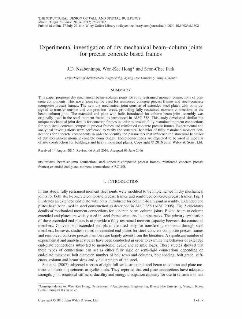
transfer force couples (tension and compression) to create fully restrained moment connections. Boltscan be designed based on either bearing type or slip critical type. Additional structural elements for thenew joints include couplers, threaded re-bar and anchor re-bar. Figs. 3 and 4 depict details of amechanical joint providing moment connections and typical beam sections for steel–concrete compos-ite precast frames and reinforced concrete precast frames, respectively. As shown in Figs. 3 and 4, thetop re-bars of beams are anchored on the rear face of beam end plates using threaded ends and nuts.Steel sections for composite beams are welded to end plates. Couplers are used to provide connectionsbetween beam plates and column plates. Anchor re-bars in a column unit are connected to beam endplates using high-strength bolts. One end of the couplers is connected to anchor re-bars in the column,and the other end is fastened with high-strength bolts. The important design parameters to transfertensile forces from beams to anchor re-bars in columns are the stiffness of end plates and sizes andlocations of bolts, allowing moment resistance at the joints. The prying action of end plates withsufficient stiffness, resisting coupled forces of tension and compression, will be precluded, contribut-ing to moment transfer through joints. The sizes of high-strength bolts should also be determined tominimize prying actions of beam end plates in order to fully restrain joints from rotation.
2.2. Stiffness of end plates
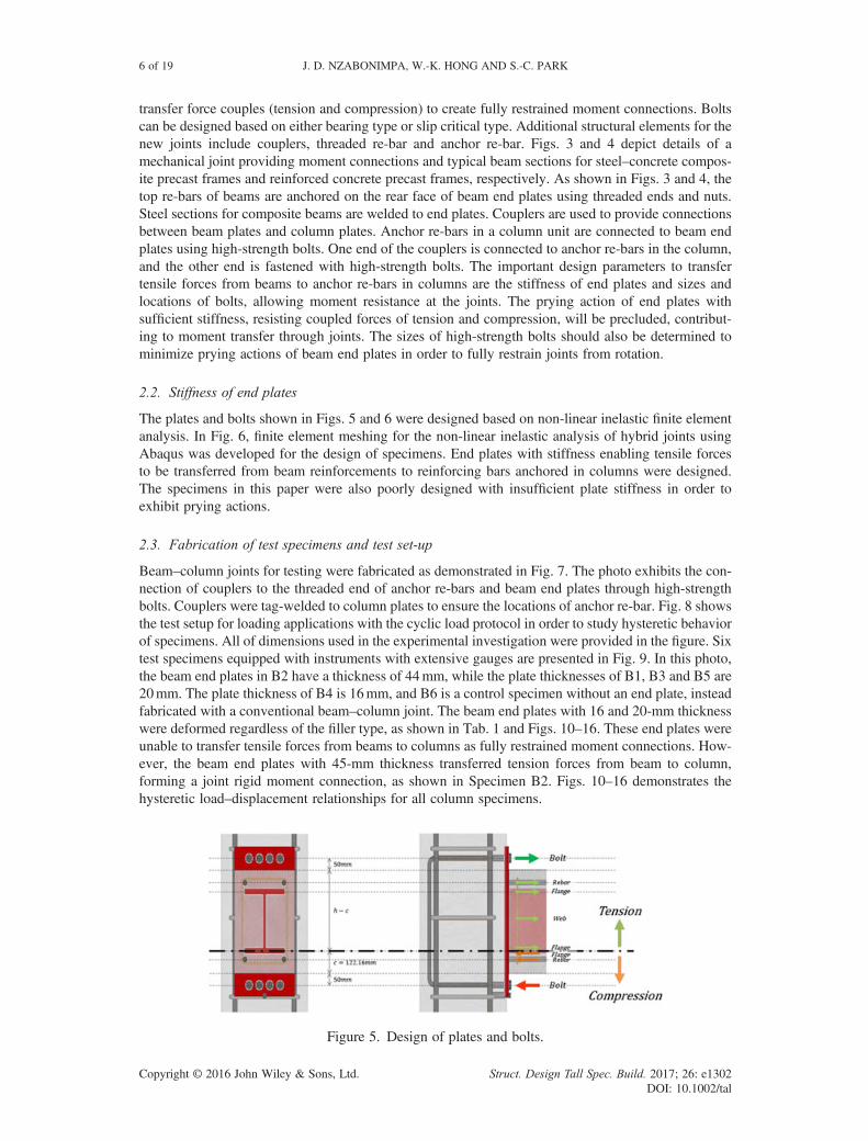
The plates and bolts shown in Figs. 5 and 6 were designed based on non-linear inelastic finite elementanalysis. In Fig. 6, finite element meshing for the non-linear inelastic analysis of hybrid joints usingAbaqus was developed for the design of specimens. End plates with stiffness enabling tensile forcesto be transferred from beam reinforcements to reinforcing bars anchored in columns were designed.The specimens in this paper were also poorly designed with insufficient plate stiffness in order toexhibit prying actions.
2.3. Fabrication of test specimens and test set-up
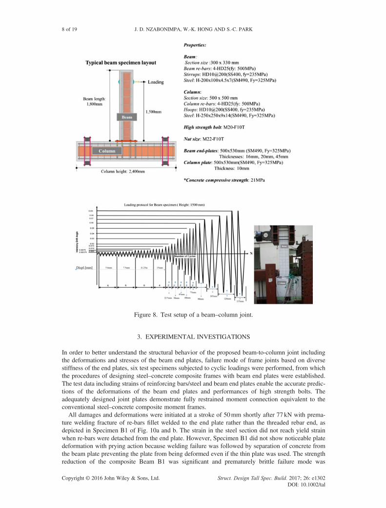
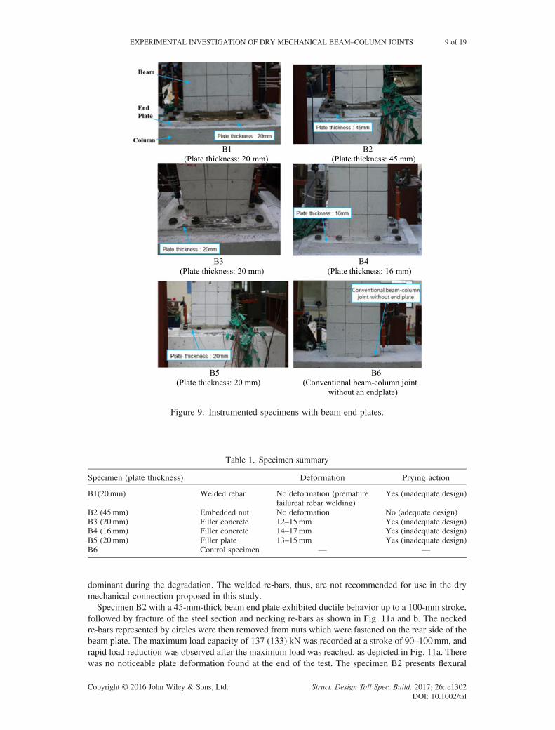
Beam–column joints for testing were fabricated as demonstrated in Fig. 7. The photo exhibits the con-nection of couplers to the threaded end of anchor re-bars and beam end plates through high-strengthbolts. Couplers were tag-welded to column plates to ensure the locations of anchor re-bar. Fig. 8 showsthe test setup for loading applications with the cyclic load protocol in order to study hysteretic behaviorof specimens. All of dimensions used in the experimental investigation were provided in the figure. Sixtest specimens equipped with instruments with extensive gauges are presented in Fig. 9. In this photo,the beam end plates in B2 have a thickness of 44mm, while the plate thicknesses of B1, B3 and B5 are20mm. The plate thickness of B4 is 16mm, and B6 is a control specimen without an end plate, insteadfabricated with a conventional beam–column joint. The beam end plates with 16 and 20-mm thicknesswere deformed regardless of the filler type, as shown in Tab. 1 and Figs. 10–16. These end plates wereunable to transfer tensile forces from beams to columns as fully restrained moment connections. How-ever, the beam end plates with 45-mm thickness transferred tension forces from beam to column,forming a joint rigid moment connection, as shown in Specimen B2. Figs. 10–16 demonstrates thehysteretic load–displacement relationships for all column specimens.
Figure 5. Design of plates and bolts.
6 of 19 J. D. NZABONIMPA, W.-K. HONG AND S.-C. PARK
Copyright © 2016 John Wiley & Sons, Ltd. Struct. Design Tall Spec. Build. 2017; 26: e1302DOI: 10.1002/tal
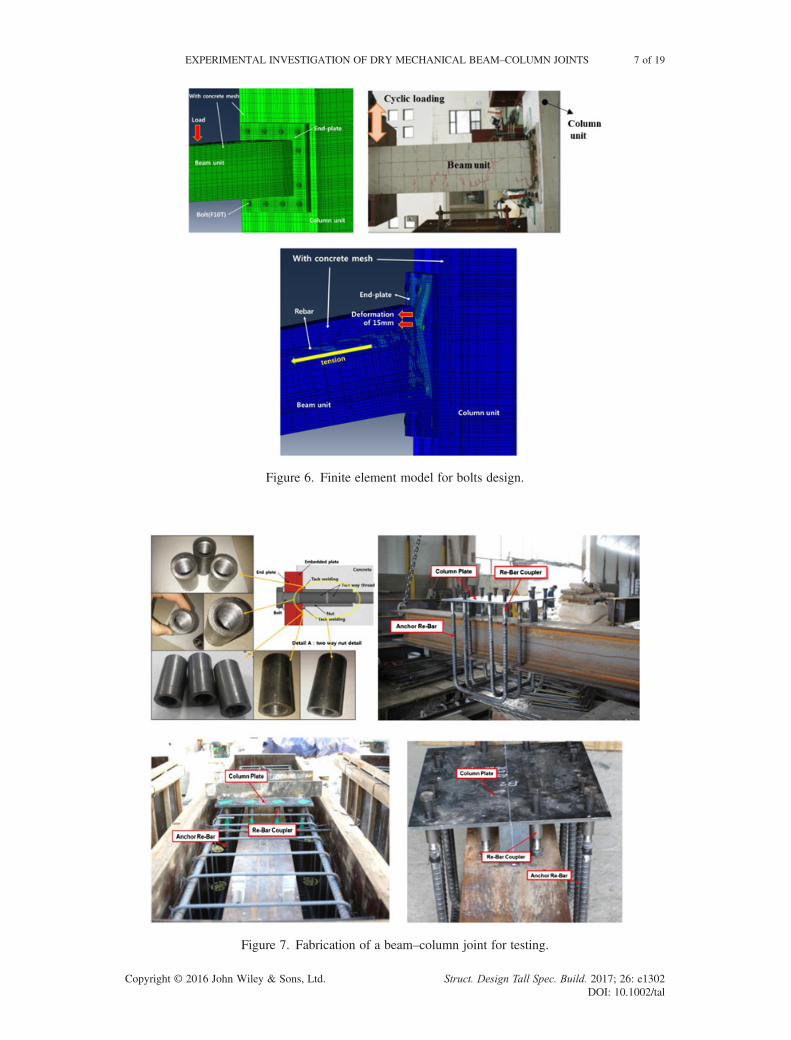
Figure 6. Finite element model for bolts design.
Figure 7. Fabrication of a beam–column joint for testing.
EXPERIMENTAL INVESTIGATION OF DRY MECHANICAL BEAM–COLUMN JOINTS 7 of 19
Copyright © 2016 John Wiley & Sons, Ltd. Struct. Design Tall Spec. Build. 2017; 26: e1302DOI: 10.1002/tal
3. EXPERIMENTAL INVESTIGATIONS
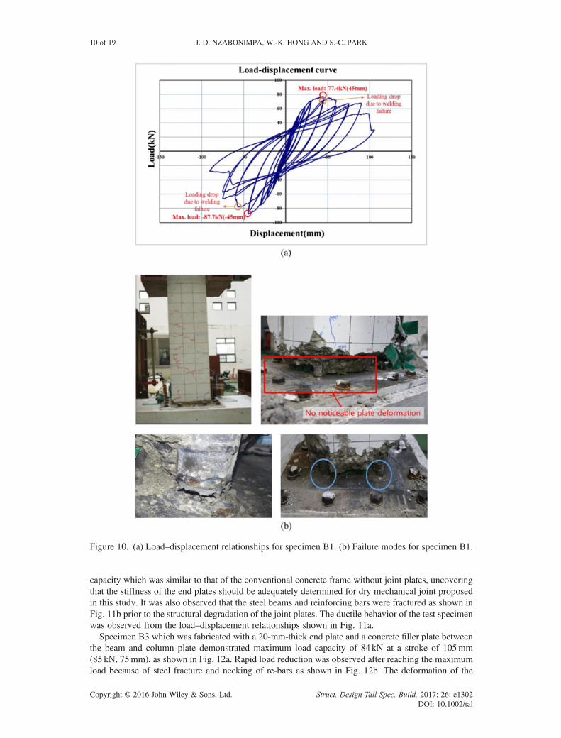
In order to better understand the structural behavior of the proposed beam-to-column joint includingthe deformations and stresses of the beam end plates, failure mode of frame joints based on diversestiffness of the end plates, six test specimens subjected to cyclic loadings were performed, from whichthe procedures of designing steel–concrete composite frames with beam end plates were established.The test data including strains of reinforcing bars/steel and beam end plates enable the accurate predic-tions of the deformations of the beam end plates and performances of high strength bolts. Theadequately designed joint plates demonstrate fully restrained moment connection equivalent to theconventional steel–concrete composite moment frames.All damages and deformations were initiated at a stroke of 50mm shortly after 77 kN with prema-
ture welding fracture of re-bars fillet welded to the end plate rather than the threaded rebar end, asdepicted in Specimen B1 of Fig. 10a and b. The strain in the steel section did not reach yield strainwhen re-bars were detached from the end plate. However, Specimen B1 did not show noticeable platedeformation with prying action because welding failure was followed by separation of concrete fromthe beam plate preventing the plate from being deformed even if the thin plate was used. The strengthreduction of the composite Beam B1 was significant and prematurely brittle failure mode was
Figure 8. Test setup of a beam–column joint.
8 of 19 J. D. NZABONIMPA, W.-K. HONG AND S.-C. PARK
Copyright © 2016 John Wiley & Sons, Ltd. Struct. Design Tall Spec. Build. 2017; 26: e1302DOI: 10.1002/tal
dominant during the degradation. The welded re-bars, thus, are not recommended for use in the drymechanical connection proposed in this study.Specimen B2 with a 45-mm-thick beam end plate exhibited ductile behavior up to a 100-mm stroke,
followed by fracture of the steel section and necking re-bars as shown in Fig. 11a and b. The neckedre-bars represented by circles were then removed from nuts which were fastened on the rear side of thebeam plate. The maximum load capacity of 137 (133) kN was recorded at a stroke of 90–100mm, andrapid load reduction was observed after the maximum load was reached, as depicted in Fig. 11a. Therewas no noticeable plate deformation found at the end of the test. The specimen B2 presents flexural
Figure 9. Instrumented specimens with beam end plates.
Table 1. Specimen summary
Specimen (plate thickness) Deformation Prying action
B1(20mm) Welded rebar No deformation (prematurefailureat rebar welding)
Yes (inadequate design)
B2 (45mm) Embedded nut No deformation No (adequate design)B3 (20mm) Filler concrete 12–15mm Yes (inadequate design)B4 (16mm) Filler concrete 14–17mm Yes (inadequate design)B5 (20mm) Filler plate 13–15mm Yes (inadequate design)B6 Control specimen — —
EXPERIMENTAL INVESTIGATION OF DRY MECHANICAL BEAM–COLUMN JOINTS 9 of 19
Copyright © 2016 John Wiley & Sons, Ltd. Struct. Design Tall Spec. Build. 2017; 26: e1302DOI: 10.1002/tal
capacity which was similar to that of the conventional concrete frame without joint plates, uncoveringthat the stiffness of the end plates should be adequately determined for dry mechanical joint proposedin this study. It was also observed that the steel beams and reinforcing bars were fractured as shown inFig. 11b prior to the structural degradation of the joint plates. The ductile behavior of the test specimenwas observed from the load–displacement relationships shown in Fig. 11a.Specimen B3 which was fabricated with a 20-mm-thick end plate and a concrete filler plate between
the beam and column plate demonstrated maximum load capacity of 84 kN at a stroke of 105mm(85 kN, 75mm), as shown in Fig. 12a. Rapid load reduction was observed after reaching the maximumload because of steel fracture and necking of re-bars as shown in Fig. 12b. The deformation of the
Figure 10. (a) Load–displacement relationships for specimen B1. (b) Failure modes for specimen B1.
10 of 19 J. D. NZABONIMPA, W.-K. HONG AND S.-C. PARK
Copyright © 2016 John Wiley & Sons, Ltd. Struct. Design Tall Spec. Build. 2017; 26: e1302DOI: 10.1002/tal

beam plate was about 12mm at maximum load and increased to 15mm at a stroke of 120mm, asshown in Fig. 12b. Specimen B3 was one of the specimens that failed to provide enough stiffnessfor dry mechanical joint. Fig. 12b and Fig. 17 present the plate deformed as much as 12–15mm.
Figure 11. (a) Load–displacement relationships for specimen B2. (b) Failure modes for specimen B2.
EXPERIMENTAL INVESTIGATION OF DRY MECHANICAL BEAM–COLUMN JOINTS 11 of 19
Copyright © 2016 John Wiley & Sons, Ltd. Struct. Design Tall Spec. Build. 2017; 26: e1302DOI: 10.1002/tal

The load–displacement relationship exhibited ductile behavior because the inelastic energy was dissi-pated during the gradual deformation of the plate before the strength was lost totally when steel flangewas fractured. The additional interior bolts, however, may be required to be installed to decreaseunsupported length between the exterior bolts to reduce deformation of the plates.Specimen B4 fabricated with a 16-mm-thick end plate and a concrete filler plate between the beam
and column plates exhibited a maximum load capacity of 72 kN in a stroke range of 120mm–225mm(73 kN, 150mm), as depicted in Fig. 13a. A constant load-bearing capacity was observed in this strokerange because the structural degradation with energy dissipation was concentrated on the beam plate,
Figure 12. (a) Load–displacement relationships for specimen B3. (b) Failure modes for specimen B3.
12 of 19 J. D. NZABONIMPA, W.-K. HONG AND S.-C. PARK
Copyright © 2016 John Wiley & Sons, Ltd. Struct. Design Tall Spec. Build. 2017; 26: e1302DOI: 10.1002/tal
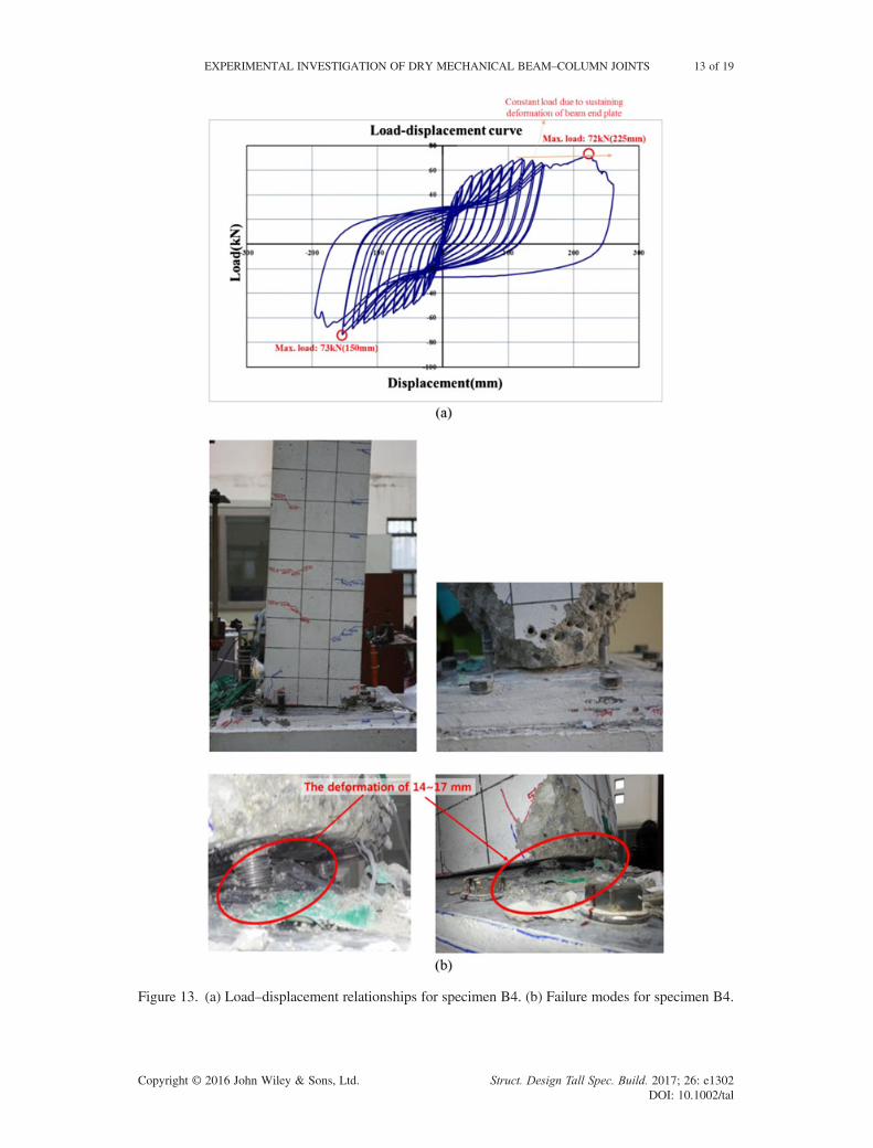
Figure 13. (a) Load–displacement relationships for specimen B4. (b) Failure modes for specimen B4.
EXPERIMENTAL INVESTIGATION OF DRY MECHANICAL BEAM–COLUMN JOINTS 13 of 19
Copyright © 2016 John Wiley & Sons, Ltd. Struct. Design Tall Spec. Build. 2017; 26: e1302DOI: 10.1002/tal
which was gradually deformed to 14mm. The deformation of the beam plate increased to around17mm at a stroke of 150mm. The concrete specimen did not show noticeable deterioration becauseall the damages were concentrated on the plate with extensive deformation as depicted in Fig. 13b.
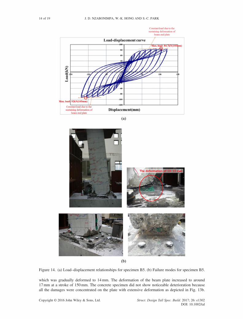
Figure 14. (a) Load–displacement relationships for specimen B5. (b) Failure modes for specimen B5.
14 of 19 J. D. NZABONIMPA, W.-K. HONG AND S.-C. PARK
Copyright © 2016 John Wiley & Sons, Ltd. Struct. Design Tall Spec. Build. 2017; 26: e1302DOI: 10.1002/tal
Specimen B4 demonstrated the least flexural strength among all test specimens because the end platewith the least stiffness with only 16mm was used at joint. Fig. 13b shows the plate deformation asmuch as 14–17mm which was responsible for the significant reduction of the flexural strength of
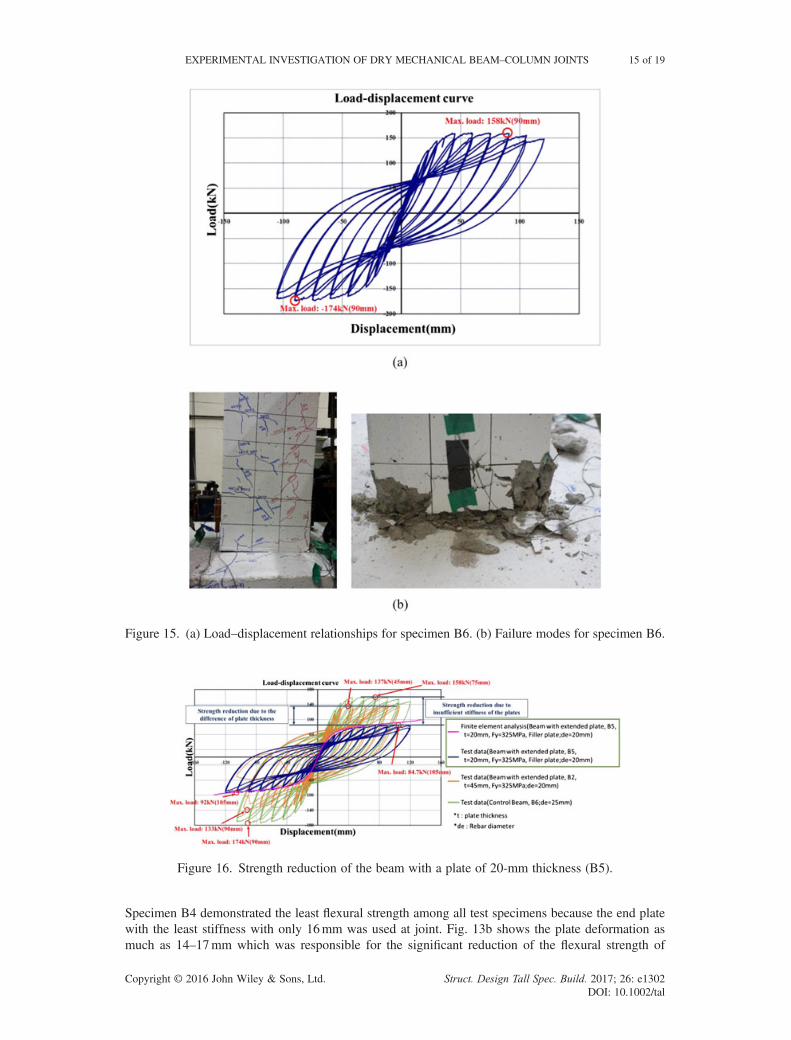
Figure 15. (a) Load–displacement relationships for specimen B6. (b) Failure modes for specimen B6.
Figure 16. Strength reduction of the beam with a plate of 20-mm thickness (B5).
EXPERIMENTAL INVESTIGATION OF DRY MECHANICAL BEAM–COLUMN JOINTS 15 of 19
Copyright © 2016 John Wiley & Sons, Ltd. Struct. Design Tall Spec. Build. 2017; 26: e1302DOI: 10.1002/tal

the specimen. Nuts were displaced during the transfer of the tension from re-bars because the deformedplate pushed nuts off the re-bar tread plane. It was inferred that the unexpected distortions of nuts andtread of re-bars can be prevented by maintaining plate deformation minimum or by providing gaps be-tween nuts and the holes prepared in plates.Specimen B5 fabricated with a 20-mm-thick end plate and steel filler plate between the beam and
column plates exhibited a maximum load capacity of 84.7 kN at a stroke of 105mm (92 kN,105mm), as depicted in Fig. 14a. A constant load-bearing capacity was observed in this stroke rangebecause the structural degradation with energy dissipation was concentrated on the beam plate. Theconcrete specimen did not show noticeable deterioration, as depicted in Fig. 14b for the same reasonobserved in Specimen B4. The deformation of 13–15mm was observed in the beam plate at a stroke ofaround 150mm as shown in Fig. 14b. The plate deformation of the Specimen B5 was predicted as15mm by finite element analysis using Abaqus as shown in deformed meshes in Fig. 6. This predictionwas well matched with the deformation measured by the experiment as illustrated in Fig. 14b. The in-elastic load displacement relationship used to design the Specimen B5 was also calculated by the non-linear inelastic FEM analysis and compared with experimental curves of the specimen with blue colorsas represented by the purple line in Fig. 16. The deformation of plate in Specimen B5 was measured as13–15mm similar to the deformation of Specimen B3 because the plate of the same 20mm thicknesswas used. The two specimens differ in that the steel filler plate was used in Specimen B5 while con-crete filler plate was in used in Specimen B3. The flexural strength of B5 was found larger than thatof B3 because the steel filler plate in B5 provided larger flexural stiffness even if the only 5% differ-ence in the flexural were measured. The displacement corresponding to the maximum load in B5 wassimilar to the displacement in B3 as shown in Fig. 12a and Fig. 14a.Specimen B6 was a control specimen with a conventional beam–column joint of a steel and rein-
forced concrete frame. Specimen B6 demonstrated a maximum load capacity of 158 kN at a strokeof 90mm (174 kN, 90mm), as depicted in Fig. 15a. The compressive failure modes were observedas loadings increased to the maximum load limit state, as depicted in Fig. 15b. The experimental hys-teretic load–displacement relationships with the plates of 45mm (B2) and 16mm (B4) are comparedwith that of control beam (B6) in Fig. 16 for beam, showing large strength reduction of the beam witha plate of 16-mm thickness (B4). The load displacement relationships of control specimen (B6) weresimilar to those of Specimen B2 built with plate stiff enough to suppress deformation. It was noted thatthe pour-forms were used to build the joint of Specimen B6; however, dry mechanical joint with beamend plates and filler plates was only used for Specimens B1, B2, B3, B4 and B5, eliminating the use oftemporary pour-forms.
Figure 17. Control beam (B6) versus beam (B2) with an extended plate.
16 of 19 J. D. NZABONIMPA, W.-K. HONG AND S.-C. PARK
Copyright © 2016 John Wiley & Sons, Ltd. Struct. Design Tall Spec. Build. 2017; 26: e1302DOI: 10.1002/tal
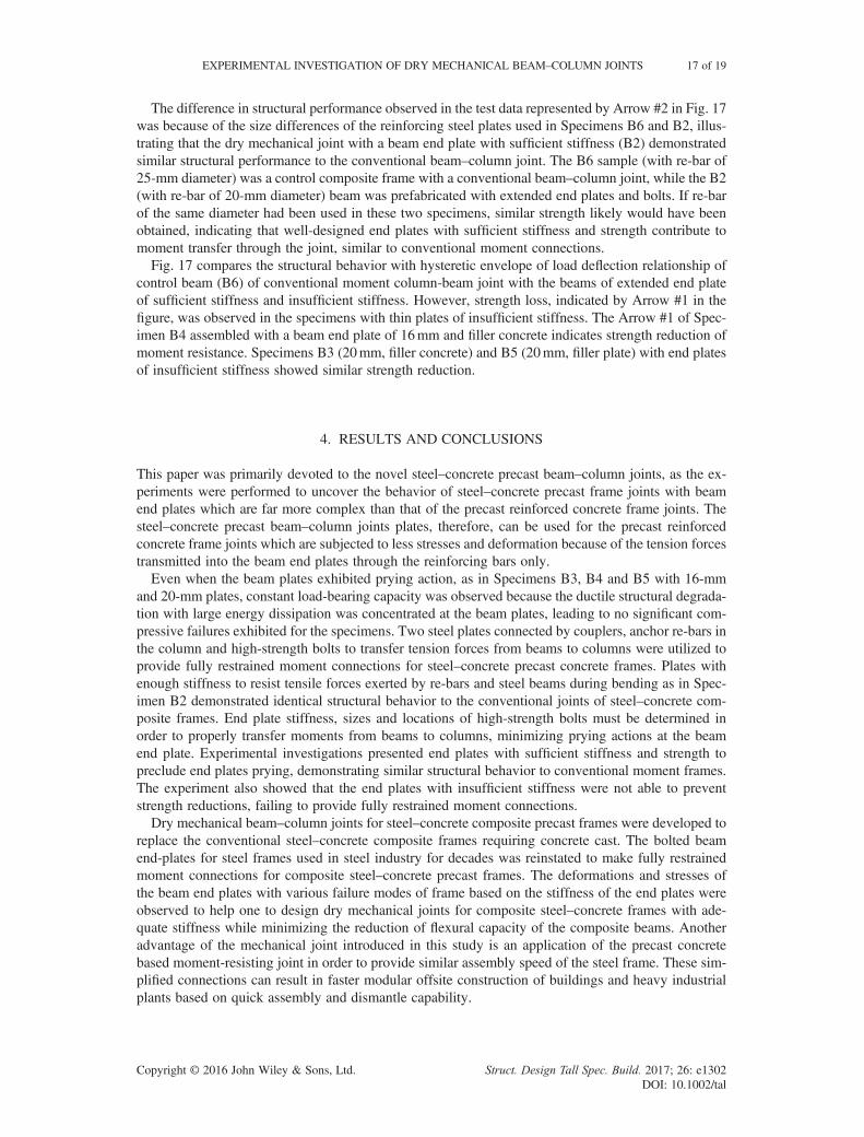
The difference in structural performance observed in the test data represented by Arrow #2 in Fig. 17was because of the size differences of the reinforcing steel plates used in Specimens B6 and B2, illus-trating that the dry mechanical joint with a beam end plate with sufficient stiffness (B2) demonstratedsimilar structural performance to the conventional beam–column joint. The B6 sample (with re-bar of25-mm diameter) was a control composite frame with a conventional beam–column joint, while the B2(with re-bar of 20-mm diameter) beam was prefabricated with extended end plates and bolts. If re-barof the same diameter had been used in these two specimens, similar strength likely would have beenobtained, indicating that well-designed end plates with sufficient stiffness and strength contribute tomoment transfer through the joint, similar to conventional moment connections.Fig. 17 compares the structural behavior with hysteretic envelope of load deflection relationship of
control beam (B6) of conventional moment column-beam joint with the beams of extended end plateof sufficient stiffness and insufficient stiffness. However, strength loss, indicated by Arrow #1 in thefigure, was observed in the specimens with thin plates of insufficient stiffness. The Arrow #1 of Spec-imen B4 assembled with a beam end plate of 16mm and filler concrete indicates strength reduction ofmoment resistance. Specimens B3 (20mm, filler concrete) and B5 (20mm, filler plate) with end platesof insufficient stiffness showed similar strength reduction.
4. RESULTS AND CONCLUSIONS
This paper was primarily devoted to the novel steel–concrete precast beam–column joints, as the ex-periments were performed to uncover the behavior of steel–concrete precast frame joints with beamend plates which are far more complex than that of the precast reinforced concrete frame joints. Thesteel–concrete precast beam–column joints plates, therefore, can be used for the precast reinforcedconcrete frame joints which are subjected to less stresses and deformation because of the tension forcestransmitted into the beam end plates through the reinforcing bars only.Even when the beam plates exhibited prying action, as in Specimens B3, B4 and B5 with 16-mm
and 20-mm plates, constant load-bearing capacity was observed because the ductile structural degrada-tion with large energy dissipation was concentrated at the beam plates, leading to no significant com-pressive failures exhibited for the specimens. Two steel plates connected by couplers, anchor re-bars inthe column and high-strength bolts to transfer tension forces from beams to columns were utilized toprovide fully restrained moment connections for steel–concrete precast concrete frames. Plates withenough stiffness to resist tensile forces exerted by re-bars and steel beams during bending as in Spec-imen B2 demonstrated identical structural behavior to the conventional joints of steel–concrete com-posite frames. End plate stiffness, sizes and locations of high-strength bolts must be determined inorder to properly transfer moments from beams to columns, minimizing prying actions at the beamend plate. Experimental investigations presented end plates with sufficient stiffness and strength topreclude end plates prying, demonstrating similar structural behavior to conventional moment frames.The experiment also showed that the end plates with insufficient stiffness were not able to preventstrength reductions, failing to provide fully restrained moment connections.Dry mechanical beam–column joints for steel–concrete composite precast frames were developed to
replace the conventional steel–concrete composite frames requiring concrete cast. The bolted beamend-plates for steel frames used in steel industry for decades was reinstated to make fully restrainedmoment connections for composite steel–concrete precast frames. The deformations and stresses ofthe beam end plates with various failure modes of frame based on the stiffness of the end plates wereobserved to help one to design dry mechanical joints for composite steel–concrete frames with ade-quate stiffness while minimizing the reduction of flexural capacity of the composite beams. Anotheradvantage of the mechanical joint introduced in this study is an application of the precast concretebased moment-resisting joint in order to provide similar assembly speed of the steel frame. These sim-plified connections can result in faster modular offsite construction of buildings and heavy industrialplants based on quick assembly and dismantle capability.
EXPERIMENTAL INVESTIGATION OF DRY MECHANICAL BEAM–COLUMN JOINTS 17 of 19
Copyright © 2016 John Wiley & Sons, Ltd. Struct. Design Tall Spec. Build. 2017; 26: e1302DOI: 10.1002/tal

ACKNOWLEDGEMENTS
This work was supported by the Technology Transfer Center for a National R&D Program (TTC)grant funded by the Korean government (MSIP) (No. 2014K000239).This research was supported by the Ministry of Land, Infrastructure and Transport (MOLIT) of the
Korean government and by the Korea Agency for Infrastructure Technology Advancement (KAIA)(No. 14AUDP-B068892-02).
REFERENCES
A Abidelah, A Bouchaïr, DE. Kerdal 2012. Experimental and analytical behavior of bolted end-plate connections with or withoutstiffeners. Journal of Constructional Steel Research, 76, 13–27. doi:10.1016/j.jcsr.2012.04.004.
Abaqus Analysis User’s Manual 6.14-2. Dassault Systèmes Simulia Corp., Providence, RI, USA.Ali Abolmaali, John H, Matthys, Mohammed Farooqi, Yeol Choi 2005. Development of moment–rotation model equations for
flush end-plate connections. Journal of Constructional Steel Research, 61, 1595–1612. DOI: 10.1016/j.jcsr.2005.05.004AISC. 2005. Prequalified connections for special and intermediate steel moment frames for seismic applications, American In-
stitute of Steel Construction. AISC 358–05, Chicago.Rui Bai, Siu-Lai Chan, Ji-Ping Hao 2015. Improved design of extended end-plate connection allowing for prying effects. Journal
of Constructional Steel Research, 113, 13–27. Doi:10.1016/j.jcsr.2015.05.008Dessouki AK, Youssef AH, Ibrahim MM. 2013. Behavior of I-beam bolted extended end-plate moment connections. Ain Shams
Engineering Journal 4: 685–699. DOI:10.1016/j.asej.2013.03.004.Concepción Díaz, Mariano Victoria, Pascual Martí, Osvaldo M. Querin 2011. FE model of beam-to-column extended end-plate
joints. Journal of Constructional Steel Research, 67, 1578–1590. doi:10.1016/j.jcsr.2011.04.002Cheng Fang, Michael CH Yam, Angus CC, Lamc, Langkun Xie. 2014. Cyclic performance of extended end-plate connections
equipped with Shape memory alloy bolts. Journal of Constructional Steel Research, 94, 122–136. Doi:10.1016/j.jcsr.2013.11.008
Charis J. Gantes, Minas E, Lemonis. 2003. Influence of equivalent bolt length in finite element modeling of T-stub steel connec-tions. Computers and Structures, 81, 595–604. DOI:10.1016/S0045-7949(03)00004-X
Cheol-Ho Lee, Jae-Hoon Kim 2007. Seismic design of reduced beam section steel moment connections with bolted web attach-ment. Journal of Constructional Steel Research, 63, 522–531. doi:10.1016/j.jcsr.2006.06.030
YI, Maggi, RM, Gonçalves, RT, Leonb, LFL, Ribeiroc 2005. Parametric analysis of steel bolted end plate connections using fi-nite element modeling. Journal of Constructional Steel Research, 61, 689–708. doi:10.1016/j.jcsr.2004.12.001
Elsayed Mashaly, Mohamed El-Heweity, Hamdy Abou-Elfath, Mohamed Osman 2011. Behavior of four-bolt extended end-plate connection subjected to lateral loading. Alexandria Engineering Journal, 50, 79–90. doi:10.1016/j.aej.2011.01.011
MR Mohamadi-shooreh, M Mofid 2008. “Parametric analyses on the initial stiffness of flush end-plate splice connections usingFEM”, Journal of Constructional Steel Research, 64, 1129–1141. doi:10.1016/j.jcsr.2007.09.010
Muresan IC, Balc R. 2015. Finite element analysis of an extended end-plate connection using the T-stub approach. Proceedingsof the International Conference on Numerical Analysis and Applied Mathematics 2014 (ICNAAM-2014), AIP ConferenceProceedings 1648: 850091. DOI:10.1063/1.4913146.
Ali Reza, Keyvani Boroujeni and Mehdi Hashemi. 2013. Linear and nonlinear analysis for seismic design of piping system.Journal of Civil Engineering and Construction Technology, vol. 4(4), 149–156. DOI:10.5897/JCECT12.090
Richard MD, Walter RJ. 2010. Design of structural steel pipe racks. Engineering Journal, fourth quarter/210/241 47(4):241–252.
Vahid Saberi, Mohsen Gerami, Ali Kheyroddin 2014. Comparison of bolted end plate and T-stub connection sensitivity to com-ponent thickness. Journal of Constructional Steel Research, 98, 134–145. Doi:10.1016/j.jcsr.2014.02.012
Gang Shi, Yongjiu Shi, Yuanqing Wang, 2007. Behaviour of end-plate moment connections under earthquake loading. Engi-neering Structures, 29, 703–716. doi:10.1016/j.engstruct.2006.06.016
Hiroshi Tagawa, Yudu Liu 2014. Stiffening of bolted end-plate connections with steel member assemblies. Journal of Construc-tional Steel Research, 103, 190–199. Doi:10.1016/j.jcsr.2014.09.005
Jingfeng Wang, Liping Chen 2012. Experimental investigation of extended end plate joints to concrete-filled steel tubularcolumns. Journal of Constructional Steel Research, 79, 56–70. Doi: 10.1016/j.jcsr.2012.07.016
Jingfeng Wang, Lin Zhang, BF, Spencer Jr. 2013. Seismic response of extended end plate joints to concrete-filled steel tubularcolumns. Engineering Structures, 49 (2013) 876–892. Doi:10.1016/j.engstruct.2013.01.001
Xiao J, Ding T, Pham TL. 2015. Seismic performance of a precast recycled concrete frame structure. ACI Structural Journal112(4): 515–524.
AUTHORS’ BIOGRAPHIES
Mr. J.D. Nzabonimpa is currently enrolled as a PhD candidate in the Department of Architectural En-gineering at Kyung Hee University, Republic of Korea. His research interest includes precast compos-ites structures.
18 of 19 J. D. NZABONIMPA, W.-K. HONG AND S.-C. PARK
Copyright © 2016 John Wiley & Sons, Ltd. Struct. Design Tall Spec. Build. 2017; 26: e1302DOI: 10.1002/tal
Dr. Won-Kee Hong is a professor of Architectural Engineering at Kyung Hee University. Dr. Hongreceived his master’s and PhD degrees from UCLA, and he worked for Englelkirk and Hart, Inc.(USA), Nihhon Sekkei (Japan), and Samsung Engineering and Construction Company (Korea) beforejoining Kyung Hee University (Korea). He also has a professional engineering license from both Koreaand the USA. Dr. Hong has more than 30 years of professional experience in structural engineering.His research interests include a new approach to construction technologies based on value engineeringwith hybrid composite structures. He provided many useful solutions to issues in current structural de-sign and construction technologies as a result of his research that combines structural engineering withconstruction technologies. He is the author of numerous papers and patents both in Korea and theUSA. Currently, Dr. Hong is developing new connections that can be used with various types offrames including hybrid steel–concrete precast composite frames (SMART frames), precast frames,and steel frames. These connections would contribute to the modular construction of heavy plant struc-tures and buildings as well.
Dr. Seon-Chee Park received his master’s and PhD degrees from Kyung Hee University in StructuralEngineering. His main research areas include an analysis of structural behavior and new approach toconstruction technologies based on composite structures.
EXPERIMENTAL INVESTIGATION OF DRY MECHANICAL BEAM–COLUMN JOINTS 19 of 19
Copyright © 2016 John Wiley & Sons, Ltd. Struct. Design Tall Spec. Build. 2017; 26: e1302DOI: 10.1002/tal

本文献由“学霸图书馆-文献云下载”收集自网络,仅供学习交流使用。
学霸图书馆(www.xuebalib.com)是一个“整合众多图书馆数据库资源,
提供一站式文献检索和下载服务”的24 小时在线不限IP
图书馆。
图书馆致力于便利、促进学习与科研,提供最强文献下载服务。
图书馆导航:
图书馆首页 文献云下载 图书馆入口 外文数据库大全 疑难文献辅助工具