Embed Size (px)
Citation preview
18th International Symposium on the Application of Laser and Imaging Techniques to Fluid Mechanics・LISBON | PORTUGAL ・JULY 4 – 7, 2016
1
Experimental investigation of a spray swirled flame in gas turbine model
combustor
E. Salaün1, 2*, P. Malbois1, 3*, A. Vandel1, G. Godard1, F. Grisch1, B. Renou1, G. Cabot1 and A. M. Boukhalfa1
1: CORIA-UMR-6614, Normandie Université, CNRS, INSA et Université de Rouen, Saint Etienne du Rouvray, France 2: Snecma, SAFRAN, Moissy-Cramayel, France
3: SAFRAN Tech, Paris-Saclay, France * Corresponding authors: [email protected]
Keywords: Combustion diagnostics, kHz OH-PLIF, kHz PIV, Turbulent swirl flame, two-phase flow, POD, Gas turbine model combustor.
ABSTRACT
Dynamical processes in gas turbine combustors play a key role in flame stabilization. Those phenomena were
investigated in a gas turbine model combustor for a partially premixed kerosene/air flame at atmospheric pressure.
The large optical accesses of the combustion chamber enable the application of laser diagnostics. Stereo-PIV, Planar
laser induced fluorescence (PLIF) of OH at 10 kHz and simultaneous particle image velocimetry (PIV) at 5 kHz have
been implemented. The flow field was characterized by PIV in front view and stereo-PIV in a horizontal plane while
the flame structure was visualized by OH-PLIF. Simultaneous OH-PLIF/PIV measurements were used to
investigate the interactions between the flow field and the flame. POD and image processing tools were developed
to analyze images. Temporal analysis of the results demonstrated the development of a local flame extinction
mechanism.
1. Introduction
Since many years, air traffic is maintaining a strong growth trend, which is expected to last for
the next few decades. The need arises to reduce noise, fuel consumption and pollutant emissions
of future aeroengines. In this context, environmental concerns and legislative regulations are
increasingly more stringent. The reduction of pollutants is then one of the driving forces in the
development of modern gas turbines (GT). To further reduce pollutant emissions, the concept of
lean premixed (LP) combustion was introduced and is considered as one of the best solution to
significantly reduce NOx emissions (Correa, 1993) (Lefebvre, 1998). However, lowering
emissions of NOx by reducing the flame temperature will compromise the flame stability and
may lead to very weak conditions increasing drastically CO and HC emissions (Huang & Yang,
2009) (Lieuwen & Yang, 2005).
Interactions between flow field and sprays and flame play a key role in GT combustors. Often, in
lean premixed gas turbines, it is common practice to stabilize flames by inducing a swirling flow.
Because of the sudden expansion at the exit of the injector and the vortex breakdown, a
recirculation zone is created (Gupta, et al., 1984). This recirculation zone transports hot products
18th International Symposium on the Application of Laser and Imaging Techniques to Fluid Mechanics・LISBON | PORTUGAL ・JULY 4 – 7, 2016
2
to the root of the flame enhancing the local ignition and therefore the stability of the flame.
Between the inflow and recirculation zones, shear layers allow the mixing between fresh and hot
gases. It is of first importance to investigate and understand the unsteady phenomena and the
complex interactions between turbulence and reactive chemistry for further studies on pollutant
formation (NOx and CO).
Detailed studies have been conducted using laboratory scaled models of GT on CH4/air flames
at atmospheric pressure using high-speed (kHz) repetition rate laser diagnostics measurements
for studying flame shape and flow structure (Meier, et al., 2010) (Stopper, et al., 2013), the flame
stabilization and ignition (Boxx, et al., 2013) , flame-vortex interaction in CH4/air flames (Stöhr,
et al., 2011) (Boxx, et al., 2012) (Stöhr, et al., 2012) (Oberleithner, et al., 2015), thermos-acoustic
oscillations/flow field interactions (Boxx, et al., 2010), fuel/air mixing (Stöhr, et al., 2015).
(Slabaugh, et al., 2015) and (Boxx, et al., 2015) examined the flame and the flow field structures in
elevated pressure conditions.
To the knowledge of the authors, simultaneous high-speed OH-PLIF/PIV has never been
applied to this industrial configuration using liquid kerosene fuel. The present work will be
carried out on a GT model combustor at atmospheric pressure. The combustion chamber is
equipped with a LP gas turbine injector supplied by TURBOMECA. This swirl injector is fueled
with commercial Jet-A1.
The objective of the present study is to investigate the flow and flame structure, and their
dynamical interactions. Large optical accesses of the combustion chamber allow the application
of laser-based diagnostics. First mean flow field where measured in front view and top view
using respectively PIV (5 kHz) and stereo-PIV (5Hz). The results enable us to understand the
main flow structures inside the combustor. Then, simultaneous PIV and planar laser induced
fluorescence of OH radical (OH-PLIF) were performed on our burner at multi-kHz repetition
rates in a complex two-phase reactive flow field with high velocities. The global flame and flow
structures were studied using averaged results whereas the flow and the flame interactions were
investigated using simultaneous results. To take advantage of the acquired high-speed
measurements post-processing tools were developed. Nonlinear filtering and active contour
method based on a level set formulation were specifically used to extract flame contour from the
OH-PLIF images. Coherent structures of the flow were visualized by the application of proper
orthogonal decomposition (POD) on the velocity field. Mechanism of local extinction of the
flame by vortices was highlighted with the temporal analysis of instantaneous measurement
sequence.
18th International Symposium on the Application of Laser and Imaging Techniques to Fluid Mechanics・LISBON | PORTUGAL ・JULY 4 – 7, 2016
3
2. Experiments
a. Swirled Burner and Operating Conditions
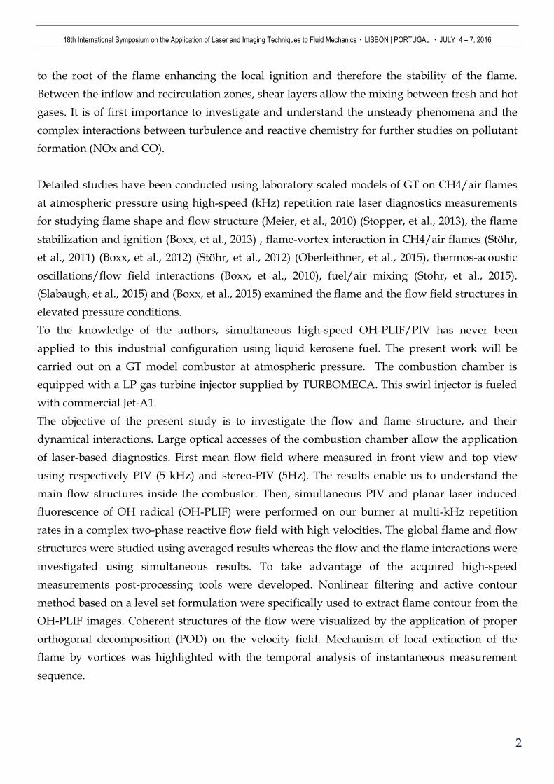
An overview of the experimental facility is given in Fig. 1. The burner is equipped with a
TURBOMECA LP, industrial swirl injector. The combustion chamber consists in a 100 mm²
square cross section and is 230 mm long, equipped with three large fused quartz optical accesses
(80x200 mm²). The exhaust directly opens on the ambient air with a 56 mm in diameter nozzle,
equipped with a gas sampling probe. The wall structure of the burner is cooled by water
circulation.
Several non-reacting and reacting conditions have been studied with this set-up but this current
study focuses on a single test condition. The swirling kerosene/air flame that is investigated has
a thermal power of 65.6 kW with an overall equivalence ratio 𝜙= 0.7 (�̇�𝑎𝑖𝑟 = 30 g/s, �̇�𝑓𝑢𝑒𝑙 = 1.417
g/s). All reacting conditions are running with commercial Jet A1 liquid fuel thus providing a
realistic configuration. For seeding the flow, a part of the main inlet air is by-passed and is
injected through a fluidized bed filled with ZrO2 particles. The seeded air is injected in the
plenum, and is mixed with the preheated air before the injection system. In order to meet closer
operating conditions encountered in industrial GT, the air inlet is preheated so that the
temperature of the air in the plenum reaches the target of 473K.
Fig. 1: Atmospheric swirled burner
b. Laser diagnostics
i. Stereo-PIV at 5Hz
The stereo-PIV system consists in a dual-cavity Q-switched Nd:YAG laser running at 5Hz
providing two 532nm laser pulses delayed of 2µs in time. A horizontal laser sheet is formed
using a spherical lens (f=1000mm) and two cylindrical lens (f1 =-20mm, f2 = 500mm), resulting in
a 70mm in width laser sheet and 500 µm thick, to minimize particle drop out of volume
JET-A1 300K
Spark Plug
Cooling System
Pressure sensor
Air inlet 473K
18th International Symposium on the Application of Laser and Imaging Techniques to Fluid Mechanics・LISBON | PORTUGAL ・JULY 4 – 7, 2016
4
measurement that occurs due to high axial velocity. Mie scattering from solid zirconium oxide
(ZrO2) particles seeded into the flow and kerosene droplets are imaged using Dantec Dynamics
FlowSense 4M cameras. To minimize the potential Mie scattering signal from kerosene droplets,
the laser sheet is set 25mm above the burner where ZrO2 particles and droplets have the same
order of size. Cameras operate with a 2048x2048 pix² resolution, and are mounted with a Nikkor
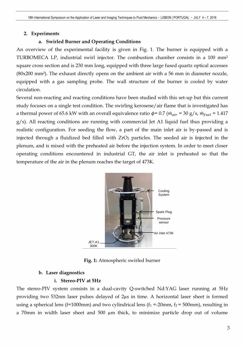
f/1.2 50mm lens. The collection systems are mounted with Scheimpflug adaptors between lenses
and cameras as they are tilted with an angle of 35° (Fig. 2). A bandpass filter centered at 532 nm
with a 10nm spectral width, is placed in front of the lens in order to suppress the flame emission
(not represented on the schema). A calibration of the two cameras is required to compensate the
perspective distortion and images are corrected (dewarping) before determining the velocity
fields. Images are then post-processed using commercial software (Dynamics Studio, Dantec)
with a multipass adaptive window cross-correlation leading to a final window size of 64x64
pixels and a 50% overlap. The three-components (U along x, V along y and W along z) of the
velocity are determined in the (x, y) plane, at an axial distance of 25 mm above the burner (Fig.
2).
Fig. 2: Schematic representation of the camera configuration for top view stereo-PIV
ii. High-Speed PIV and High-Speed OH-PLIF diagnostics
Spatial flame front location and associated instantaneous flow field are obtained from high-
speed OH-PLIF at 10 kHz repetition rate combined with high-speed PIV at 5 kHz.
The OH-PLIF system consists in a Nd-YAG-laser operating at 527 nm wavelength, generating
pulses at 10 kHz repetition rate, with an average power of 105 W. The laser pumps a tunable dye
laser (Sirah Credo with Rhodamine 590 solved in ethanol). At 10 kHz, the resultant output pulse
energy is 350 µJ/pulse in the probe volume. The wavelength is tuned to the Q1(5) line of the
𝐴2Σ+ ← 𝑋2Π(0,1) transition of OH (𝜆 = 282,675nm). This wavelength is adjusted using the
fluorescence signal emitted by a laminar CH4/air flame. The laser beam is superimposed with
the PIV beam, using a dichroic mirror and is expanded through a set of fused silica lenses (𝑓1 =
25mm
𝒚 𝒙
𝒛
𝒙 𝜶 = 𝟑𝟓°
18th International Symposium on the Application of Laser and Imaging Techniques to Fluid Mechanics・LISBON | PORTUGAL ・JULY 4 – 7, 2016
5
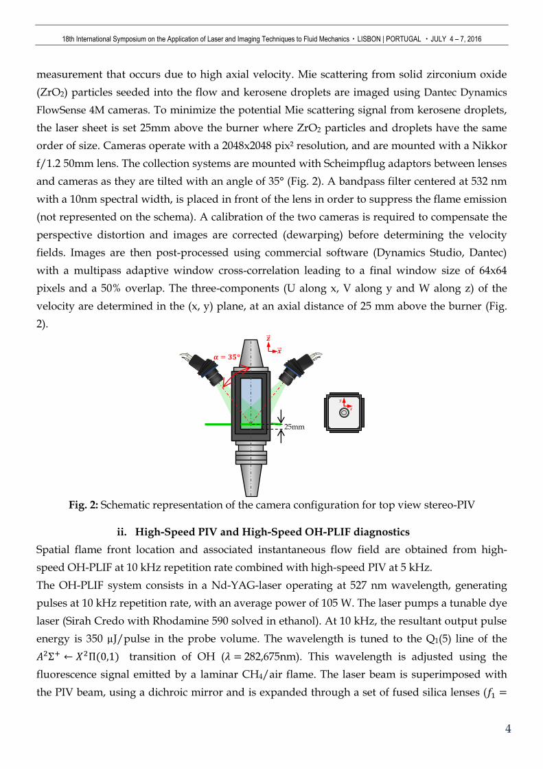
1000 𝑚𝑚, 𝑓2 = −20 𝑚𝑚, 𝑓3 = 500 𝑚𝑚) to form a laser sheet of 50 mm in height (Fig. 3).
Fluorescence signal is collected using an external image intensifier (High-Speed IRO, LaVision)
mounted on a CMOS camera (Fastcam SA5) operating with a 896x848 pix² resolution. A
B.HALLE UV lens (Nachfl. GmbH 100mm f/2) is mounted on a Scheimpflug system as the
camera is tilted by 27.5° in configuration 1 (Fig. 4 Left) and 13.5° in configuration 2 (away from
the laser sheet normal). Intensifier gate is set to 100 ns, with an intensifier gain set around 65, and
background noise (especially elastic and Mie scattering) is reduced using a high-pass Schott
WG295 filter and a bandpass Schott UG11 filter .
For high-speed PIV, the laser system consists in a double cavity Nd:YLF Laser, DarwinDual,
Quantronix operating at 527nm, generating doubled pulses with a pulse energy of 6mJ/pulse.
The Mie scattering signal from droplets and ZrO2 is collected with a Photron SA1.1 camera
equipped with a Nikkor 80mm, f/1.4 operating at 10 kHz, with images (single frames) separated
by 5µs in configuration 1 or 2.5 µs in configuration 2 (time between pulses) and with a 768x768
pix² resolution. A bandpass filter centered at 532nm is also placed behind the lens. The images
are then imported and post-processed with Dynamics Studio software. A multipass adaptive
window cross-correlation with a final window size of 16x16 pixels and a 50% overlap is applied.
No filter is used on PIV results, only spurious vectors (in x and z component velocity) are
suppressed.
.
Fig. 3: Schematic representation of the dual kHz measurement technique
a. Pressure oscillations
Pressure fluctuations are recorded with a Kistler 7001 piezoelectric pressure sensor at 20 kHz to
evaluate the stability of the flame. The pressure sensor is mounted on a waveguide system in the
combustion chamber at 30mm above the injector.
L1: spherical lens, f = 1000mm L2: cylindrical lens, f = -20mm L3: cylindrical lens, f = 500mm O
H-P
LIF
LA
SE
R
𝒙
𝒚
PIV
LA
SE
R #
1
PIV
LA
SE
R #
2
BEAM COMBINER C
OL
LE
CT
ION
SY
ST
EM
DY
E L
AS
ER
SIR
AH
CR
ED
O
PU
MP
LA
SE
R N
d-Y
AG
53
2n
m
282,65 nm 527 nm
Wa
ll
L1 L2 L3
PIV
LA
SE
R
18th International Symposium on the Application of Laser and Imaging Techniques to Fluid Mechanics・LISBON | PORTUGAL ・JULY 4 – 7, 2016
6
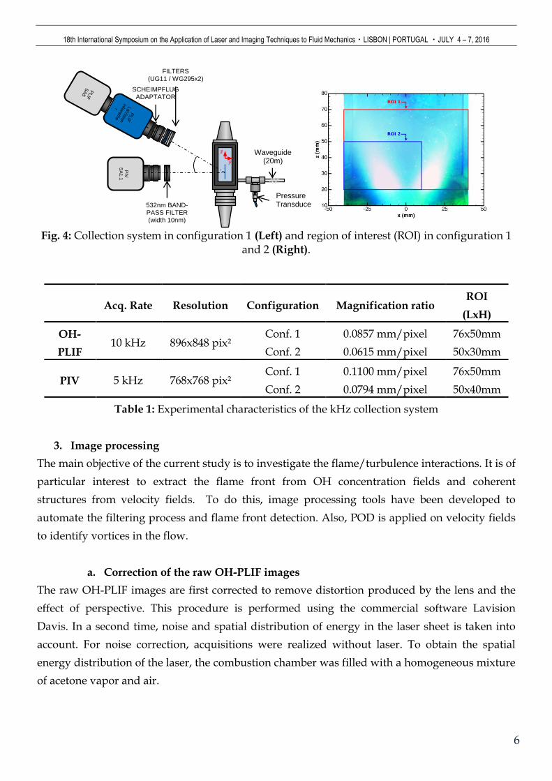
Fig. 4: Collection system in configuration 1 (Left) and region of interest (ROI) in configuration 1
and 2 (Right).
Acq. Rate Resolution Configuration Magnification ratio ROI
(LxH)
OH-
PLIF 10 kHz 896x848 pix²
Conf. 1 0.0857 mm/pixel 76x50mm
Conf. 2 0.0615 mm/pixel 50x30mm
PIV 5 kHz 768x768 pix² Conf. 1 0.1100 mm/pixel 76x50mm
Conf. 2 0.0794 mm/pixel 50x40mm
Table 1: Experimental characteristics of the kHz collection system
3. Image processing
The main objective of the current study is to investigate the flame/turbulence interactions. It is of
particular interest to extract the flame front from OH concentration fields and coherent
structures from velocity fields. To do this, image processing tools have been developed to
automate the filtering process and flame front detection. Also, POD is applied on velocity fields
to identify vortices in the flow.
a. Correction of the raw OH-PLIF images
The raw OH-PLIF images are first corrected to remove distortion produced by the lens and the
effect of perspective. This procedure is performed using the commercial software Lavision
Davis. In a second time, noise and spatial distribution of energy in the laser sheet is taken into
account. For noise correction, acquisitions were realized without laser. To obtain the spatial
energy distribution of the laser, the combustion chamber was filled with a homogeneous mixture
of acetone vapor and air.
Waveguide (20m)
Pressure Transducer
PIV
SA
1.1
𝒛 𝒚
SCHEIMPFLUG ADAPTATOR
FILTERS (UG11 / WG295x2)
532nm BAND-PASS FILTER (width 10nm)
18th International Symposium on the Application of Laser and Imaging Techniques to Fluid Mechanics・LISBON | PORTUGAL ・JULY 4 – 7, 2016
7
Fluorescence on the acetone vapor is carried out to obtain the energy profile of the laser sheet.
Images were corrected using the following relation:
𝐼𝑐𝑜𝑟𝑟𝑒𝑐𝑡𝑒𝑑 =𝐼𝑟𝑎𝑤− < 𝐼𝑛𝑜𝑖𝑠𝑒 >
< 𝐼𝑎𝑐𝑒𝑡𝑜𝑛𝑒 > − < 𝐼𝑛𝑜𝑖𝑠𝑒 > (1)
Where <. > is the temporal averaging operator.
b. Nonlinear diffusion filter
A main difficulty in high-repetition rate OH-PLIF lies in the very limited energy per pulse
(350µJ/pulse). Local maxima of OH concentration gradient are good markers of the flame front
location. Because of noise features, the position of the flame front cannot be easily extracted from
raw images. Corrected OH-PLIF images (Fig. 5-Left) need to be filtered before executing the
contour detection routine. Also, high-speed diagnostics generate huge datasets. So, the
computational time for the filtering procedure must be reasonable, and must be applied on the
different images with fixed parameters.
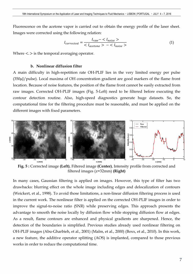
Fig. 5 : Corrected image (Left), Filtered image (Center), Intensity profile from corrected and
filtered images (z=32mm) (Right)
In many cases, Gaussian filtering is applied on images. However, this type of filter has two
drawbacks: blurring effect on the whole image including edges and delocalization of contours
(Weickert, et al., 1998). To avoid those limitations, a non-linear diffusion filtering process is used
in the current work. The nonlinear filter is applied on the corrected OH-PLIF images in order to
improve the signal-to-noise ratio (SNR) while preserving edges. This approach presents the
advantage to smooth the noise locally by diffusion flow while stopping diffusion flow at edges.
As a result, flame contours are enhanced and physical gradients are sharpened. Hence, the
detection of the boundaries is simplified. Previous studies already used nonlinear filtering on
OH-PLIF images (Abu-Gharbieh, et al., 2001) (Malm, et al., 2000) (Boxx, et al., 2010). In this work,
a new feature, the additive operator splitting (AOS) is implanted, compared to those previous
works in order to reduce the computational time.
18th International Symposium on the Application of Laser and Imaging Techniques to Fluid Mechanics・LISBON | PORTUGAL ・JULY 4 – 7, 2016
8
This method based on the work of (Perona & Malik, 1990) and (Catté, et al., 1992), consists in
solving the following partial derivative equation (PDE):
𝜕𝑢
𝜕𝑡= 𝑑𝑖𝑣(𝑔(|𝛻𝑢σ|2)𝛻𝑢)
𝑢0 = 𝑢(𝑥, 𝑦, 𝑡 = 0) = 𝐼
(2)
The basic idea of this filtering procedure is to reduce the diffusivity at edges. Edges are detected
by |𝛻𝑢σ|2. A diffusivity function 𝑔(|𝛻𝑢σ|2) is introduced and its definition is based on the work
of (Perona & Malik, 1990):
𝑔(|𝛻𝑢σ|2) =
1
1 + (|𝛻𝑢σ|
λ)
2 (3)
𝑢𝜎 is a Gaussian smoothed version of 𝑢, where 𝜎 is the standard deviation of the Gaussian
kernel used for the convolution. The aim of this Gaussian smoothing is a spatial regularization of
the PDE solving procedure (Catté, et al., 1992). Spatial regularization guarantees that the solution
converges to a constant steady-state. Also, spatial regularization makes the filter insensitive to
noise at scales smaller than 𝜎 (Weickert, 1998). The parameter 𝜆 is called the contrast parameter.
Lower gradient intensity values than 𝜆 are diffused.
The numerical implantation of this filter requires a discretization of the previous PDE (eq.2) and
solves it using an iterative process. The simplest approach is based on explicit scheme, but for
stability reason, this method is severely restricted to very small time steps. The introduction of a
semi-implicit scheme would be a good alternative.
In matrix notation, the discretized PDE can be re-written as follow:
𝑢𝑡+1 − 𝑢𝑡
Δ𝑡= 𝒜(𝑢𝑡)𝑢𝑡+1 (4)
Where 𝒜(𝒖𝑘𝑡 ) is a matrix defined as:
𝒜(𝑢𝑘𝑡 ) = [𝑎𝑖,𝑗(𝑢
𝑡)]
𝑤𝑖𝑡ℎ 𝑎𝑖,𝑗(𝑢𝑡) =
{
𝑔𝑖𝑡 + 𝑔𝑗
𝑡
2𝑗 ∈ 𝒩(𝑖)
− ∑𝑔𝑖𝑡 + 𝑔𝑗
𝑡
2𝑛∈𝒩(𝑖)
𝑗 = 𝑖
0 , 𝑜𝑡ℎ𝑒𝑟𝑤𝑖𝑠𝑒
(5)
A reformulation of the (eq.4) gives:
𝑢𝑡+1 = (𝐼𝑑 −Δ𝑡𝒜(𝑢𝑡))−1
𝑢𝑡 (6)
𝑢𝑖𝑡+1 can be solved directly but this method is computationally inefficient because of the
numerous linear system of equations to solve. Considering an image of size M x N, the linear
18th International Symposium on the Application of Laser and Imaging Techniques to Fluid Mechanics・LISBON | PORTUGAL ・JULY 4 – 7, 2016
9
system to solve would have a size (M x N) x (M x N). A solution to this issue is the AOS
(additive operator splitting) method proposed by (Weickert, et al., 1998)
𝑢𝑖𝑡+1 = (𝐼𝑑 −Δ𝑡 ∑ 𝒜𝑙(𝑢
𝑡)
𝑙∈{𝑥,𝑦}
)
−1
𝑢𝑡 (7)
Finally, 𝑢𝑖𝑡+1 can be calculated by solving two linear systems of M x N equations. Using semi-
implicit scheme with AOS, the computational cost is increased, compared to the explicit scheme
but time steps are no more limited. Thus, the global computation time is reduced.
A filtered OH-PLIF image can be observed in Fig. 5-Center. The effect of the nonlinear filter can
clearly been seen on Fig. 5-Right. For comparison purposes, profiles of pixel intensities at
z=32mm are extracted from the corrected and the filtered images, and then are plotted on the
same chart. The parameter 𝜆 is chosen in order to smooth noise in the low intensity regions while
it preserves high gradients of the image corresponding to the flame front. In the luminous
regions (high concentration of OH radical), the noise is less smoothed but this is not an issue for
flame detection.
c. Flame front detection
After the filtering process on the corrected images, a contour detection procedure is applied.
Classical approaches to extract the position of the flame front position are based on the
magnitude of gradients. Images are previously filtered, and in spite of that, classical procedure
found in literature failed to define the flame front location.
In medical studies, researchers are often faced with the challenge to segment noisy images in
order to identify blood vessel, tumor... An emerging solution concerning the segmentation of
medical images especially medical resonance images (MRI) is active contour based on level-set
method. In this work, active contours using level set method are used to extract the position of
the flame front.
The basic idea of active contour is to initiate a first curve around the object to be detected; this
curve moves towards to its interior normal and has to stop on the boundary object. The initial
curve 𝒞0 is represented implicitly within a higher dimension function. Usually 𝒞0 is embedded as
the zero level set of a function 𝜙(𝑥) by using the signed distance function. In the interior
region 𝜙(𝑥) < 0, and outside 𝜙(𝑥) > 0. A PDE is governing the time evolution of the function 𝜙
and at each time the zero level set of this function gives the contour. The PDE to solve depends
on the chosen active contour model.
The method used in our work is a geodesic region-based level set segmentation method. In
geodesic active contour (GAC) introduced by (Caselles, et al., 1995), the basic idea is to start with
18th International Symposium on the Application of Laser and Imaging Techniques to Fluid Mechanics・LISBON | PORTUGAL ・JULY 4 – 7, 2016
10
a curve around the object to be detected, the curves move towards to its interior normal and has
to stop on the boundary object. Image gradients are used to construct an edge stopping function
to keep the contour evolution within the boundary. The Chan-Vese region-based level set model
(Chan & Vese, 2001), assumes two different homogeneous regions to be partitioned. (Rousson &
Deriche, 2002) proposed a modification of the energy functional to take into account second
order variation. Then, regions are characterized by statistical properties such as mean and
standard deviation.
The image segmentation is based on the minimization of a variational functional. To minimize
the problem, the level set 𝜙(𝑥) is introduced and the resolution is done by taking the Euler-
Lagrange equations and update the level set function 𝜙(𝑥) by the gradient descent method. The
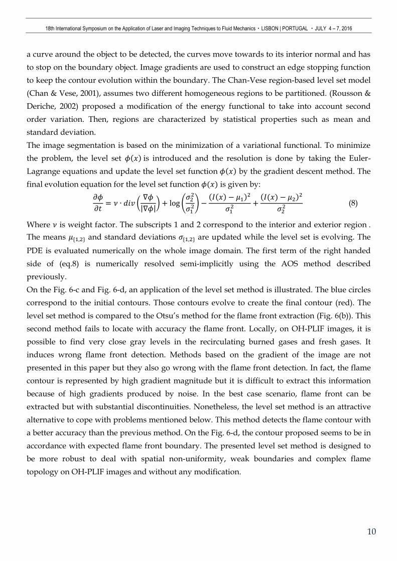
final evolution equation for the level set function 𝜙(𝑥) is given by:
𝜕𝜙
𝜕𝑡= 𝜈 ∙ 𝑑𝑖𝑣 (
∇𝜙
|∇𝜙|) + log (
𝜎22
𝜎12) −
(𝐼(𝑥) − 𝜇1)2
𝜎12 +
(𝐼(𝑥) − 𝜇2)2
𝜎22 (8)
Where 𝜈 is weight factor. The subscripts 1 and 2 correspond to the interior and exterior region .
The means 𝜇{1,2} and standard deviations 𝜎{1,2} are updated while the level set is evolving. The
PDE is evaluated numerically on the whole image domain. The first term of the right handed
side of (eq.8) is numerically resolved semi-implicitly using the AOS method described
previously.
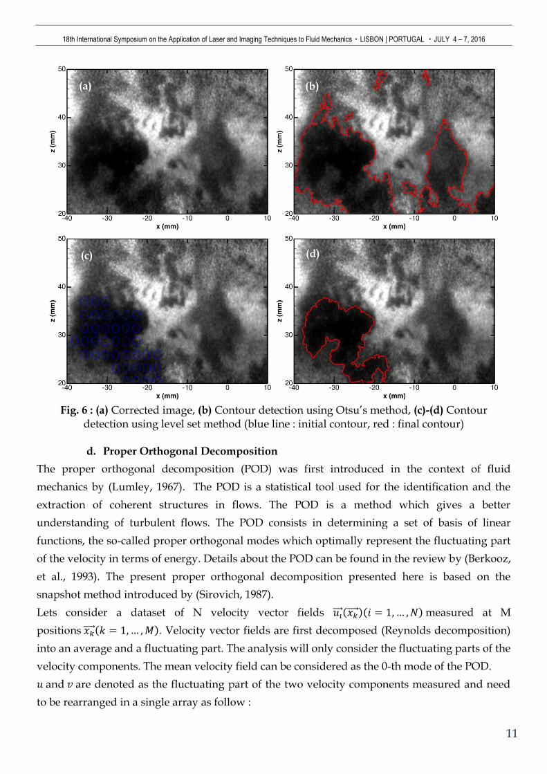
On the Fig. 6-c and Fig. 6-d, an application of the level set method is illustrated. The blue circles
correspond to the initial contours. Those contours evolve to create the final contour (red). The
level set method is compared to the Otsu’s method for the flame front extraction (Fig. 6(b)). This
second method fails to locate with accuracy the flame front. Locally, on OH-PLIF images, it is
possible to find very close gray levels in the recirculating burned gases and fresh gases. It
induces wrong flame front detection. Methods based on the gradient of the image are not
presented in this paper but they also go wrong with the flame front detection. In fact, the flame
contour is represented by high gradient magnitude but it is difficult to extract this information
because of high gradients produced by noise. In the best case scenario, flame front can be
extracted but with substantial discontinuities. Nonetheless, the level set method is an attractive
alternative to cope with problems mentioned below. This method detects the flame contour with
a better accuracy than the previous method. On the Fig. 6-d, the contour proposed seems to be in
accordance with expected flame front boundary. The presented level set method is designed to
be more robust to deal with spatial non-uniformity, weak boundaries and complex flame
topology on OH-PLIF images and without any modification.
18th International Symposium on the Application of Laser and Imaging Techniques to Fluid Mechanics・LISBON | PORTUGAL ・JULY 4 – 7, 2016
11
Fig. 6 : (a) Corrected image, (b) Contour detection using Otsu’s method, (c)-(d) Contour
detection using level set method (blue line : initial contour, red : final contour)
d. Proper Orthogonal Decomposition
The proper orthogonal decomposition (POD) was first introduced in the context of fluid
mechanics by (Lumley, 1967). The POD is a statistical tool used for the identification and the
extraction of coherent structures in flows. The POD is a method which gives a better
understanding of turbulent flows. The POD consists in determining a set of basis of linear
functions, the so-called proper orthogonal modes which optimally represent the fluctuating part
of the velocity in terms of energy. Details about the POD can be found in the review by (Berkooz,
et al., 1993). The present proper orthogonal decomposition presented here is based on the
snapshot method introduced by (Sirovich, 1987).
Lets consider a dataset of N velocity vector fields 𝑢𝑖 (𝑥𝑘 )(𝑖 = 1, … , 𝑁) measured at M
positions 𝑥𝑘 (𝑘 = 1, … , 𝑀). Velocity vector fields are first decomposed (Reynolds decomposition)
into an average and a fluctuating part. The analysis will only consider the fluctuating parts of the
velocity components. The mean velocity field can be considered as the 0-th mode of the POD.
𝑢 and 𝑣 are denoted as the fluctuating part of the two velocity components measured and need
to be rearranged in a single array as follow :
(a)
(c)
(b)
(d)
18th International Symposium on the Application of Laser and Imaging Techniques to Fluid Mechanics・LISBON | PORTUGAL ・JULY 4 – 7, 2016
12
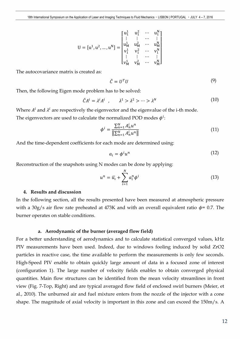
U = [u1, u2, … , uN] =
[ u1
1 u12 ⋯ u1
N
⋮ ⋮ ⋯ ⋮uM
1 uM2 ⋯ uM
N
v11 v1
2 ⋯ v1N
⋮ ⋮ ⋯ ⋮vM
1 vM2 ⋯ vM
N ]
The autocovariance matrix is created as:
�̃� = 𝑈𝑇𝑈 (9)
Then, the following Eigen mode problem has to be solved:
�̃�𝐴𝑖 = 𝜆𝑖𝐴𝑖 , 𝜆1 > 𝜆2 > ⋯ > 𝜆𝑁 (10)
Where 𝐴𝑖 and 𝜆𝑖 are respectively the eigenvector and the eigenvalue of the i-th mode.
The eigenvectors are used to calculate the normalized POD modes 𝜙𝑖:
𝜙𝑖 =∑ 𝐴𝑛
𝑖 𝑢𝑛𝑁𝑛=1
‖∑ 𝐴𝑛𝑖 𝑢𝑛𝑁
𝑛=1 ‖ (11)
And the time-dependent coefficients for each mode are determined using:
𝑎𝑖 = 𝜙𝑖𝑢𝑛 (12)
Reconstruction of the snapshots using N modes can be done by applying:
𝑢𝑛 = 𝑢�̅� + ∑ 𝑎𝑖𝑛𝜙𝑖
𝑁
𝑖=1
(13)
4. Results and discussion
In the following section, all the results presented have been measured at atmospheric pressure
with a 30g/s air flow rate preheated at 473K and with an overall equivalent ratio 𝜙= 0.7. The
burner operates on stable conditions.
a. Aerodynamic of the burner (averaged flow field)
For a better understanding of aerodynamics and to calculate statistical converged values, kHz
PIV measurements have been used. Indeed, due to windows fooling induced by solid ZrO2
particles in reactive case, the time available to perform the measurements is only few seconds.
High-Speed PIV enable to obtain quickly large amount of data in a focused zone of interest
(configuration 1). The large number of velocity fields enables to obtain converged physical
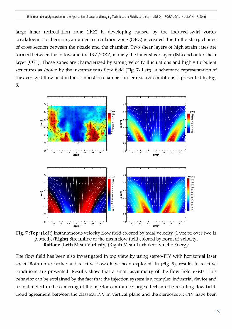
quantities. Main flow structures can be identified from the mean velocity streamlines in front
view (Fig. 7-Top, Right) and are typical averaged flow field of enclosed swirl burners (Meier, et
al., 2010). The unburned air and fuel mixture enters from the nozzle of the injector with a cone
shape. The magnitude of axial velocity is important in this zone and can exceed the 150m/s. A
18th International Symposium on the Application of Laser and Imaging Techniques to Fluid Mechanics・LISBON | PORTUGAL ・JULY 4 – 7, 2016
13
large inner recirculation zone (IRZ) is developing caused by the induced-swirl vortex
breakdown. Furthermore, an outer recirculation zone (ORZ) is created due to the sharp change
of cross section between the nozzle and the chamber. Two shear layers of high strain rates are
formed between the inflow and the IRZ/ORZ, namely the inner shear layer (ISL) and outer shear
layer (OSL). Those zones are characterized by strong velocity fluctuations and highly turbulent
structures as shown by the instantaneous flow field (Fig. 7- Left). A schematic representation of
the averaged flow field in the combustion chamber under reactive conditions is presented by Fig.
8.
Fig. 7 :Top: (Left) Instantaneous velocity flow field colored by axial velocity (1 vector over two is
plotted), (Right) Streamline of the mean flow field colored by norm of velocity.
Bottom: (Left) Mean Vorticity; (Right) Mean Turbulent Kinetic Energy
The flow field has been also investigated in top view by using stereo-PIV with horizontal laser
sheet. Both non-reactive and reactive flows have been explored. In (Fig. 9), results in reactive
conditions are presented. Results show that a small asymmetry of the flow field exists. This
behavior can be explained by the fact that the injection system is a complex industrial device and
a small defect in the centering of the injector can induce large effects on the resulting flow field.
Good agreement between the classical PIV in vertical plane and the stereoscopic-PIV have been
18th International Symposium on the Application of Laser and Imaging Techniques to Fluid Mechanics・LISBON | PORTUGAL ・JULY 4 – 7, 2016
14
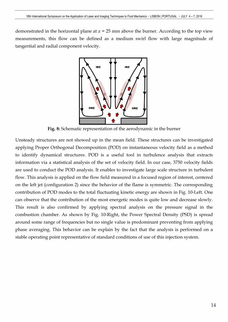
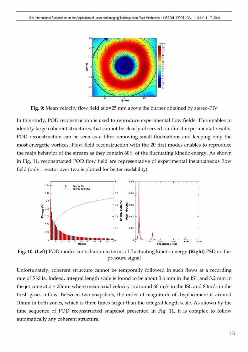
demonstrated in the horizontal plane at z = 25 mm above the burner. According to the top view
measurements, this flow can be defined as a medium swirl flow with large magnitude of
tangential and radial component velocity.
Fig. 8: Schematic representation of the aerodynamic in the burner
Unsteady structures are not showed up in the mean field. These structures can be investigated
applying Proper Orthogonal Decomposition (POD) on instantaneous velocity field as a method
to identify dynamical structures. POD is a useful tool in turbulence analysis that extracts
information via a statistical analysis of the set of velocity field. In our case, 3750 velocity fields
are used to conduct the POD analysis. It enables to investigate large scale structure in turbulent
flow. This analysis is applied on the flow field measured in a focused region of interest, centered
on the left jet (configuration 2) since the behavior of the flame is symmetric. The corresponding
contribution of POD modes to the total fluctuating kinetic energy are shown in Fig. 10-Left. One
can observe that the contribution of the most energetic modes is quite low and decrease slowly.
This result is also confirmed by applying spectral analysis on the pressure signal in the
combustion chamber. As shown by Fig. 10-Right, the Power Spectral Density (PSD) is spread
around some range of frequencies but no single value is predominant preventing from applying
phase averaging. This behavior can be explain by the fact that the analysis is performed on a
stable operating point representative of standard conditions of use of this injection system.
18th International Symposium on the Application of Laser and Imaging Techniques to Fluid Mechanics・LISBON | PORTUGAL ・JULY 4 – 7, 2016
15
Fig. 9: Mean velocity flow field at z=25 mm above the burner obtained by stereo-PIV
In this study, POD reconstruction is used to reproduce experimental flow fields. This enables to
identify large coherent structures that cannot be clearly observed on direct experimental results.
POD reconstruction can be seen as a filter removing small fluctuations and keeping only the
most energetic vortices. Flow field reconstruction with the 20 first modes enables to reproduce
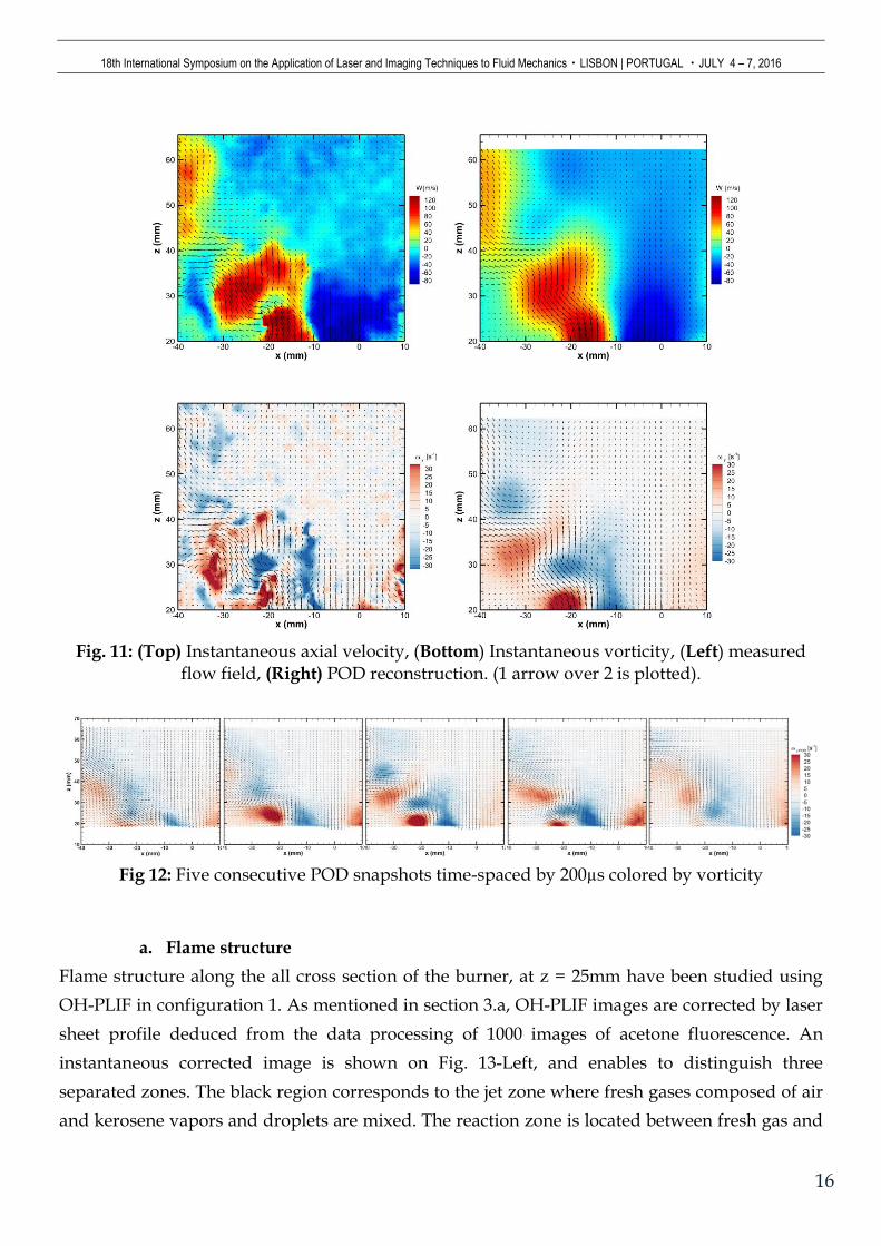
the main behavior of the stream as they contain 60% of the fluctuating kinetic energy. As shown
in Fig. 11, reconstructed POD flow field are representative of experimental instantaneous flow
field (only 1 vector over two is plotted for better readability).
Fig. 10: (Left) POD modes contribution in terms of fluctuating kinetic energy (Right) PSD on the
pressure signal
Unfortunately, coherent structure cannot be temporally followed in such flows at a recording
rate of 5 kHz. Indeed, integral length scale is found to be about 3.6 mm in the ISL and 3.2 mm in
the jet zone at z = 25mm where mean axial velocity is around 60 m/s in the ISL and 80m/s in the
fresh gases inflow. Between two snapshots, the order of magnitude of displacement is around
10mm in both zones, which is three times larger than the integral length scale. As shown by the
time sequence of POD reconstructed snapshot presented in Fig. 11, it is complex to follow
automatically any coherent structure.
18th International Symposium on the Application of Laser and Imaging Techniques to Fluid Mechanics・LISBON | PORTUGAL ・JULY 4 – 7, 2016
16
Fig. 11: (Top) Instantaneous axial velocity, (Bottom) Instantaneous vorticity, (Left) measured
flow field, (Right) POD reconstruction. (1 arrow over 2 is plotted).
Fig 12: Five consecutive POD snapshots time-spaced by 200µs colored by vorticity
a. Flame structure
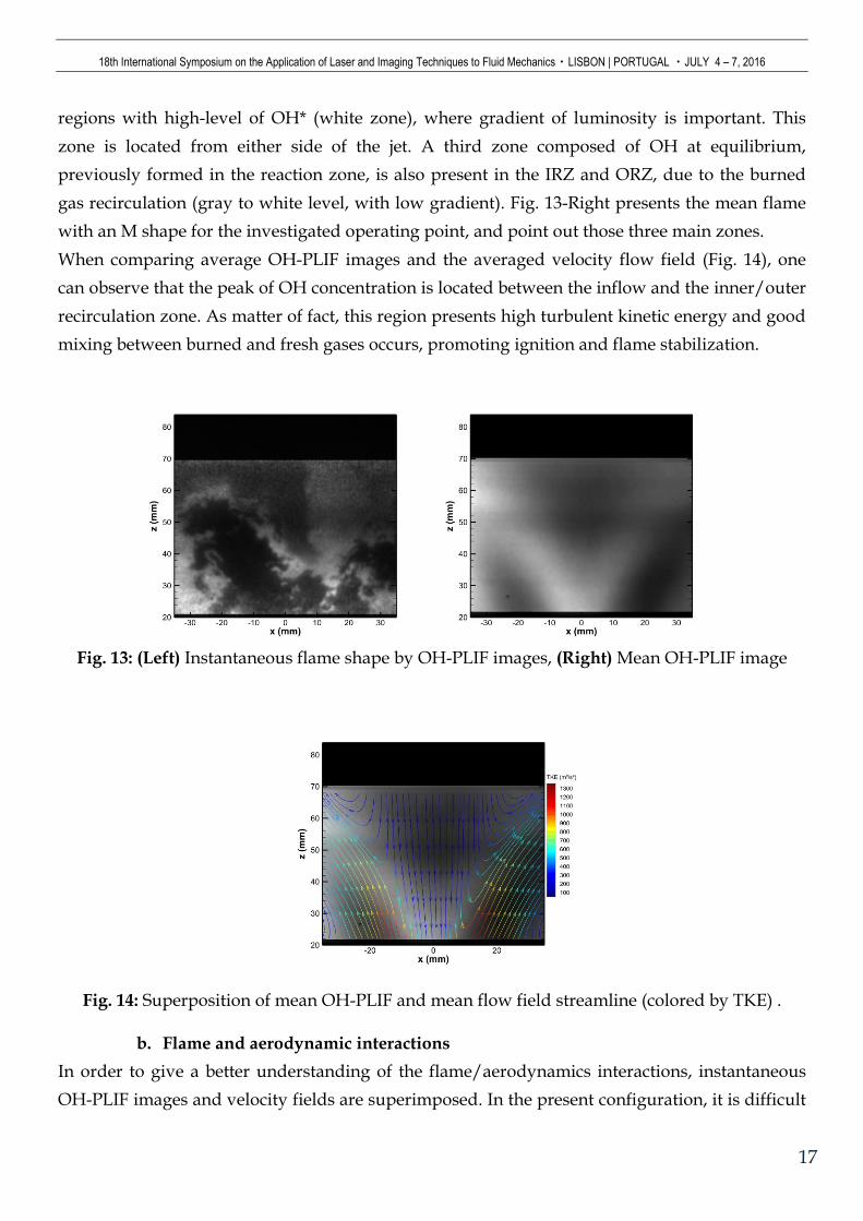
Flame structure along the all cross section of the burner, at z = 25mm have been studied using
OH-PLIF in configuration 1. As mentioned in section 3.a, OH-PLIF images are corrected by laser
sheet profile deduced from the data processing of 1000 images of acetone fluorescence. An
instantaneous corrected image is shown on Fig. 13-Left, and enables to distinguish three
separated zones. The black region corresponds to the jet zone where fresh gases composed of air
and kerosene vapors and droplets are mixed. The reaction zone is located between fresh gas and
18th International Symposium on the Application of Laser and Imaging Techniques to Fluid Mechanics・LISBON | PORTUGAL ・JULY 4 – 7, 2016
17
regions with high-level of OH* (white zone), where gradient of luminosity is important. This
zone is located from either side of the jet. A third zone composed of OH at equilibrium,
previously formed in the reaction zone, is also present in the IRZ and ORZ, due to the burned
gas recirculation (gray to white level, with low gradient). Fig. 13-Right presents the mean flame
with an M shape for the investigated operating point, and point out those three main zones.
When comparing average OH-PLIF images and the averaged velocity flow field (Fig. 14), one
can observe that the peak of OH concentration is located between the inflow and the inner/outer
recirculation zone. As matter of fact, this region presents high turbulent kinetic energy and good
mixing between burned and fresh gases occurs, promoting ignition and flame stabilization.
Fig. 13: (Left) Instantaneous flame shape by OH-PLIF images, (Right) Mean OH-PLIF image
Fig. 14: Superposition of mean OH-PLIF and mean flow field streamline (colored by TKE) .
b. Flame and aerodynamic interactions
In order to give a better understanding of the flame/aerodynamics interactions, instantaneous
OH-PLIF images and velocity fields are superimposed. In the present configuration, it is difficult
18th International Symposium on the Application of Laser and Imaging Techniques to Fluid Mechanics・LISBON | PORTUGAL ・JULY 4 – 7, 2016
18
to follow temporally flame roll-up or local extinction. Indeed, successive OH-PLIF images are
often uncorrelated due to the important out of plane velocity component and relatively low
repetition rate of OH-PLIF laser compared to the order of magnitude of velocity in the jet zone.
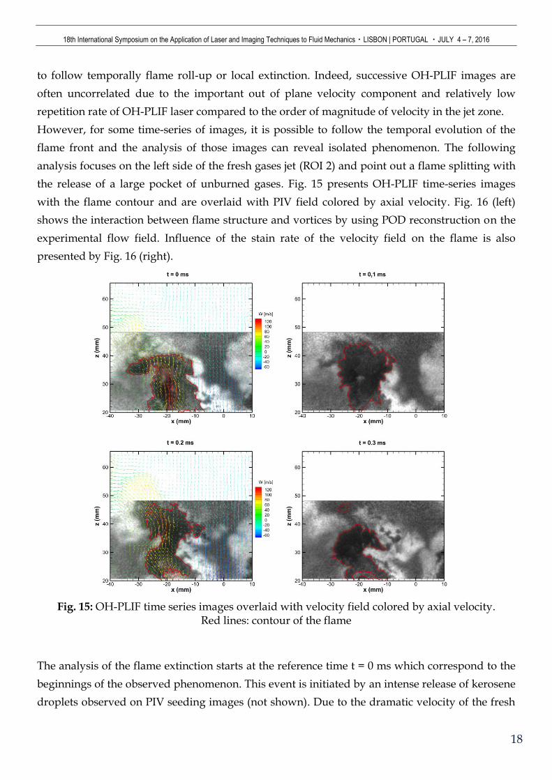
However, for some time-series of images, it is possible to follow the temporal evolution of the
flame front and the analysis of those images can reveal isolated phenomenon. The following
analysis focuses on the left side of the fresh gases jet (ROI 2) and point out a flame splitting with
the release of a large pocket of unburned gases. Fig. 15 presents OH-PLIF time-series images
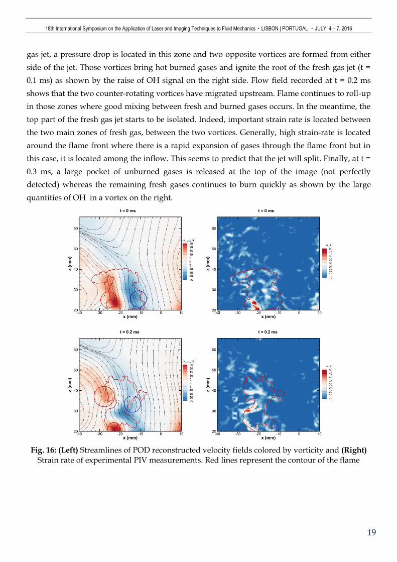
with the flame contour and are overlaid with PIV field colored by axial velocity. Fig. 16 (left)
shows the interaction between flame structure and vortices by using POD reconstruction on the
experimental flow field. Influence of the stain rate of the velocity field on the flame is also
presented by Fig. 16 (right).
Fig. 15: OH-PLIF time series images overlaid with velocity field colored by axial velocity.
Red lines: contour of the flame
The analysis of the flame extinction starts at the reference time t = 0 ms which correspond to the
beginnings of the observed phenomenon. This event is initiated by an intense release of kerosene
droplets observed on PIV seeding images (not shown). Due to the dramatic velocity of the fresh
18th International Symposium on the Application of Laser and Imaging Techniques to Fluid Mechanics・LISBON | PORTUGAL ・JULY 4 – 7, 2016
19
gas jet, a pressure drop is located in this zone and two opposite vortices are formed from either
side of the jet. Those vortices bring hot burned gases and ignite the root of the fresh gas jet (t =
0.1 ms) as shown by the raise of OH signal on the right side. Flow field recorded at t = 0.2 ms
shows that the two counter-rotating vortices have migrated upstream. Flame continues to roll-up
in those zones where good mixing between fresh and burned gases occurs. In the meantime, the
top part of the fresh gas jet starts to be isolated. Indeed, important strain rate is located between
the two main zones of fresh gas, between the two vortices. Generally, high strain-rate is located
around the flame front where there is a rapid expansion of gases through the flame front but in
this case, it is located among the inflow. This seems to predict that the jet will split. Finally, at t =
0.3 ms, a large pocket of unburned gases is released at the top of the image (not perfectly
detected) whereas the remaining fresh gases continues to burn quickly as shown by the large
quantities of OH in a vortex on the right.
Fig. 16: (Left) Streamlines of POD reconstructed velocity fields colored by vorticity and (Right)
Strain rate of experimental PIV measurements. Red lines represent the contour of the flame
18th International Symposium on the Application of Laser and Imaging Techniques to Fluid Mechanics・LISBON | PORTUGAL ・JULY 4 – 7, 2016
20
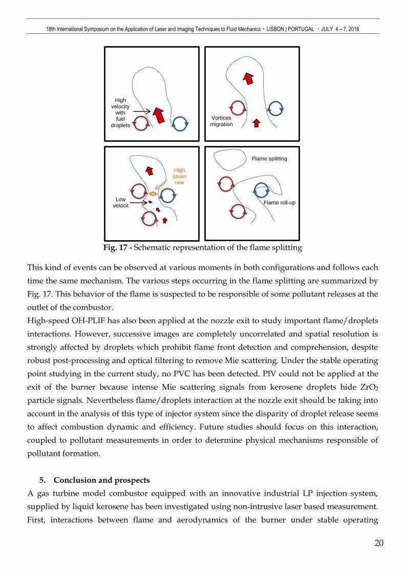
Fig. 17 - Schematic representation of the flame splitting
This kind of events can be observed at various moments in both configurations and follows each
time the same mechanism. The various steps occurring in the flame splitting are summarized by
Fig. 17. This behavior of the flame is suspected to be responsible of some pollutant releases at the
outlet of the combustor.
High-speed OH-PLIF has also been applied at the nozzle exit to study important flame/droplets
interactions. However, successive images are completely uncorrelated and spatial resolution is
strongly affected by droplets which prohibit flame front detection and comprehension, despite
robust post-processing and optical filtering to remove Mie scattering. Under the stable operating
point studying in the current study, no PVC has been detected. PIV could not be applied at the
exit of the burner because intense Mie scattering signals from kerosene droplets hide ZrO2
particle signals. Nevertheless flame/droplets interaction at the nozzle exit should be taking into
account in the analysis of this type of injector system since the disparity of droplet release seems
to affect combustion dynamic and efficiency. Future studies should focus on this interaction,
coupled to pollutant measurements in order to determine physical mechanisms responsible of
pollutant formation.
5. Conclusion and prospects
A gas turbine model combustor equipped with an innovative industrial LP injection system,
supplied by liquid kerosene has been investigated using non-intrusive laser based measurement.
First, interactions between flame and aerodynamics of the burner under stable operating
High strain rate
Low velocit
y
High velocity
with fuel
droplets
Vortices migration
Flame splitting
Flame roll-up
18th International Symposium on the Application of Laser and Imaging Techniques to Fluid Mechanics・LISBON | PORTUGAL ・JULY 4 – 7, 2016
21
conditions have been studied by “classical” PIV and OH-PLIF diagnostics. The M-shape of the
flame and the aerodynamics in the chamber are typical of enclosed swirl flames. The generation
of large inner recirculation zones and good mixing between fresh and burned gases in the inner
shear layers enable to ignite and stabilize the flame in those regions.
In a second part, high-speed PIV coupled to high-speed OH-PLIF measurements were
implemented in a focused region of interest to investigate instantaneous flame/turbulence
interactions. To extract instantaneous and statistical values from high-speed measurements,
efficient post-processing methods were developed like flame front extraction using nonlinear
filtering and level set method segmentation or POD analysis on velocity flow field. POD of the
velocity fields shows that in stable operating conditions, no modes are predominant. We also
observed that PIV and OH-PLIF measurements, in most of cases, are not temporally resolved at
10 kHz. But time-series images can be isolated and some events such as flame extinction or
inhomogeneous combustion can be analyzed. In the current study, the origin of a local
extinction, resulting in a large release of unburned reactant was analyzed. An inhomogeneous
release of droplets, turbulence and their interaction with the flame govern this phenomenon.
Future measurements will be based on standard low-speed measurement like OH-PLIF, NO-
PLIF and CO-PLIF at 10Hz. The aim of the future work will be to correlate flame front, and
pollutant formation.
Effect of pressure will also be analyzed using a new high-pressure optical combustor facility to
meet more realistic aeronautical operating conditions.
6. Acknowledgments
The authors are grateful for the support of the TURBOMECA and the technical help from the
CORIA workshop staff.
7. References
Abu-Gharbieh, R., Kaminski, C., Gustavsson, T. & Hamarneh, G., 2001. Flame front matching and
tracking in plif images using geodesic paths and level sets. s.l., s.n., pp. 112-118.
Berkooz, G., Holmes, P. & Lumley, J. L., 1993. The proper orthogonal decomposition in the
analysis of turbulent flows. Annual review of fluid mechanics, 25(1), pp. 539-575.
Boxx, I., Arndt, C. M., Carter, C. D. & Meier, W., 2012. High-speed laser diagnostics for the study
of flame dynamics in a lean premixed gas turbine model combustor. Experiments in Fluids, 52(3),
pp. 555-567.
Boxx, I., Carter, C. D., Stöhr, M. & Meier, W., 2013. Study of the mechanisms for flame
stabilization in gas turbine model combustors using kHz laser diagnostics. Experiments in Fluids,
54(5).
18th International Symposium on the Application of Laser and Imaging Techniques to Fluid Mechanics・LISBON | PORTUGAL ・JULY 4 – 7, 2016
22
Boxx, I. et al., 2015. 3kHz PIV/OH-PLIF measurements in a gas turbine combustor at elevated
pressure. Proceedings of the Combustion Institute, 35(3), pp. 3793-3802.
Boxx, I., Stöhr, M., Carter, C. & Meier, W., 2010. Temporally resolved planar measurements of
transient phenomena in a partially pre-mixed swirl flame in a gas turbine model combustor.
Combustion and Flame, 157(8), pp. 1510-1525.
Caselles, V., Kimmel, R. & Sapiro, G., 1995. Geodesic active contours. s.l., s.n., pp. 694-699.
Catté, F., Lions, P.-L., Morel, J.-M. & Coll, T., 1992. Image selective smoothing and edge detection
by nonlinear diffusion. SIAM Journal on Numerical analysis, 29(1), pp. 182-193.
Chan, T. F. & Vese, L. A., 2001. Active contours without edges. Image processing, IEEE transactions
on, 10(2), pp. 266-277.
Correa, S. M., 1993. A review of NOx formation under gas-turbine combustion conditions.
Combustion science and technology, 87(1-6), pp. 329-362.
Gupta, A. K., Lilley, D. G. & Syred, N., 1984. Swirl flows.. Issue 488, pp. p., 1..
Huang, Y. & Yang, V., 2009. Dynamics and stability of lean-premixed swirl-stabilized
combustion. Progress in Energy and Combustion Science, 35(4), pp. 293-364.
Lefebvre, A. H., 1998. Gas turbine combustion. s.l.:CRC press.
Lieuwen, T. C. & Yang, V., 2005. Combustion instabilities in gas turbine engines(operational
experience, fundamental mechanisms and modeling). Progress in astronautics and aeronautics.
Lumley, J. L., 1967. The structure of inhomogeneous turbulent flows. Atmospheric turbulence and
radio wave propagation, pp. 166-178.
Malm, H., Sparr, G., Hult, J. & Kaminski, C. F., 2000. Nonlinear diffusion filtering of images
obtained by planar laser-induced fluorescence spectroscopy. JOSA A, 17(12), pp. 2148-2156.
Meier, W., Boxx, I., Stöhr, M. & Carter, C. D., 2010. Laser-based investigations in gas turbine
model combustors. Experiments in Fluids, 49(4), pp. 865-882.
Oberleithner, K. et al., 2015. Formation and flame-induced suppression of the precessing vortex
core in a swirl combustor: experiments and linear stability analysis.. 162(8), pp. 3100-3114.
Perona, P. & Malik, J., 1990. Scale-space and edge detection using anisotropic diffusion. Pattern
Analysis and Machine Intelligence, IEEE Transactions on, 12(7), pp. 629-639.
Rousson, M. & Deriche, R., 2002. A variational framework for active and adaptative segmentation of
vector valued images. s.l., s.n., pp. 56-61.
Sirovich, L., 1987. Turbulence and the dynamics of coherent structures. Part I: Coherent
structures. Quarterly of applied mathematics, 45(3), pp. 561-571.
Slabaugh, C. D., Pratt, A. C. & Lucht, R. P., 2015. Simultaneous 5 kHz OH-PLIF/PIV for the
study of turbulent combustion at engine conditions. Applied Physics B, 118(1), pp. 109-130.
Stöhr, M., Arndt, C. & Meier, W., 2015. Transient effects of fuel–air mixing in a partially-
premixed turbulent swirl flame. Proceedings of the Combustion Institute, 35(3), pp. 3327-3335.
18th International Symposium on the Application of Laser and Imaging Techniques to Fluid Mechanics・LISBON | PORTUGAL ・JULY 4 – 7, 2016
23
Stöhr, M., Boxx, I., Carter, C. D. & Meier, W., 2012. Experimental study of vortex-flame
interaction in a gas turbine model combustor. Combustion and Flame, 159(8), pp. 2636-2649.
Stöhr, M., Sadanandan, R. & Meier, W., 2011. Phase-resolved characterization of vortex–flame
interaction in a turbulent swirl flame. Experiments in Fluids, 51(4), pp. 1153-1167.
Stopper, U. et al., 2013. Experimental study of industrial gas turbine flames including
quantification of pressure influence on flow field, fuel/air premixing and flame shape.
Combustion and Flame, 160(10), pp. 2103-2118.
Weickert, J., 1998. Anisotropic diffusion in image processing. Stuttgart: Teubner.: s.n.
Weickert, J., Romeny, B. T. H. & Viergever, M. A., 1998. Efficient and reliable schemes for
nonlinear diffusion filtering. Image Processing, IEEE Transactions on, 7(3), pp. 398-410.


![Experimental Evaluation of Spray Reduction Technologies1356870/FULLTEXT01.pdf1964,[2]). In previous years, spray deflection has become more interesting to ship designers leading to](https://img.pdfslide.us/doc/110x75/610dd78ba05d346f8d086432/experimental-evaluation-of-spray-reduction-1356870fulltext01pdf-19642-in.jpg)