Embed Size (px)
Citation preview
NUREG/CR-4527SAND86-0336Vol. 2
\n Experimental Investigation)f Internally Ignited Firesn Nuclear Power Plant,ontrol Cabinets'art I1: Room Effects Tests
repared by J.M. Chavez, S.P. Nowlen
andia National Laboratories
repared for
.S. Nuclear Regulatoryommission
NOTICE
This report was prepared as an account of work sponsored by an agency of the United StatesGovernment. Neither the United States Government nor any agency thereof, or any of theiremployees, makes any warranty, expressed or implied, or assumes any legal liability of re-sponsibility for any third party's use, or the results of such use. of any information, apparatus,product or process disclosed in this report, or represents that its use by such third party wouldnot infringe privately owned rights.
NOTICE
Availability of Reference Materials Cited in NRC Publications
Most documents cited in NRC publications will be available from one of the followmna sojrcsn
1 The NRC Public Document Room. 1717 H Street, N.W.Washington. DC 20555
2. The Superintendent of Documents. U.S. Gowvrnment Printinci Olticu. P,,s, Of! ,- cu, 317082.
Washington, DC 20013-7082
3, The National Technical Information Service, Springfield, VA 22161
Although the listing that follows represents the majority oh documents cited in NRC publicationsit is not intended to be exhaustive.
Referenced docb .nents available for inspection and copying for a fee from the NRC Public Document Room include NRC correspondence and internal NRC memoranda; NRC Oft ,e of Inspectionand Enforcement bulletins, circulars, information notices, inspection and investigation notices:Licensee Event Reports; vendor reports and correspondence; Commission papers; and applicant andlicensee documents and correspondence.
The following documents in the NUREG series are available for purchase from the GPO SalesProgram: formal NRC staff and contractor reports, NRC sponsored conference proceedmnas. andNRC booklets and brochures. Also available are Regulatory Guides. NRC requlations in tne Cocde ofFederal Regulations, and Nuclear Regulatory Commission Issuances.Documents available from the National Technical Information Service include NUREG seriesreports and technical reports prepared by other federal agencies and renorts prepared by ttie AtomicEnergy Commission, forerunner agency to the Nuclear Regulatory Commission.
Documents available from public and special technical libraries include all open literature items,such as books, journal and periodical articles, and transactions. Federal Register notices. federai andstate legislation, and congressional reports can usually be obtained from these hibraries.
Documents such as theses, dissertations, foreign reports and translations, and non-NRC cunferenceproceedings are available for purchase from the organization sponsorinq the nublication cited
Single copies of NRC draft reports are available free, to the extent of supply, upon writtenrequest to the Division of Information Support Services, Distribution Section. U.S. NuclearRegulatory Commission, Washington, DC 20555.
Copies of industry codes and standards used in a substantive mranner in tr~e *-.RC reau .3tory processare maintained at the NRC Library. 7920 Norfolk Avenue Bethesda, Mlaryiand. ajn are avatiablethere for reference use by the public. Codes and standards are usually corsvriqhteri e,;1 mac bepurchased from the originating organization or, if they are American Naticonai Stanoards. from theAmerican National Standards Institute, 1430 Broadway, New York, NY 100 I8.

NUREG/CR-4527SAND86-0336Vol. 2RP
kn Experimental Investigationif Internally Ignited Firesi Nuclear Power PlantOontrol Cabinets3rt I1: Room Effects Tests
3nuscript Completed: October 1988ite Published: November 1988
epared byM. Chavez, S.P. Nowlen
india National Laboratoriesbuquerque, NM 87185
repared for'ivision of Engineeringiffice of Nuclear Regulatory ResearchI.S. Nuclear Regulatory CommissionIashington, DC 20555IRC FIN A1010


ABSTRACT
This report presents the findings of the second part of a two-part seriesof full-scale electrical cabinet fire tests conducted by Sandia NationalLaboratories for the U.S. Nuclear Regulatory Commission. The first partof this test series investigated the effects of various cabinet parameterson a cabinet fire. The second part of the test series, described here,investigated the effects of such a fire on a large (18.3x12.2x6.1-m or60x4Ox20-ft) enclosure.
Five tests involving a fire in a control cabinet were conducted under Part2 of the test series. These tests investigated the effects of fuel type,cabinet configuration, and enclosure ventilation rate on the developmentof the enclosure environment. Although fires as large as 1300 kWresulted, enclosure peak temperatures (outside the fire plume itself) weretypically less than 1500C, with significant vertical thermalstratification observed. The most significant impact on the testenclosure environment was that dense smoke, in all cases, resulted intotal obscuration of the enclosure within 6-15 min of fire ignition.Enclosure ventilation rates as high as 8 room air changes per hour werefound to be ineffective in purging the smoke from this large enclosure.Similar obscuration problems had also been observed in the Part 1 tests,which utilized a smaller enclosure with ventilation rates as high as 15room air changes per hour.
iii/iv


CONTENTS
Page
ABSTRACT iii
ACKNOWLEDGMENTS ix
EXECUTIVE SUMMARY 1
1. INTRODUCTION 5
1.1 Background 5
1.2 Previous Studies 5
2. MATERIALS AND METHODS 8
2.1 Test Facility and Instrumentation 8
2.2 Test Materials and Arrangements 11
2.2.1 Control Room Mockup 11
2.2.2 Cabinets 11
2.2.3 Ignition Sources 11
2.2.4 In Situ Fuels 15
2.3 Cabinet Instrumentation 16
3. DISCUSSION OF CABINET AND CONTROL ROOM FIRE TESTS 18
3.1 Gas Burner Tests in Benchboard Cabinets (Tests 21 and 22) 18
3.2 Benchboard Cabinet Fire Tests (Tests 23 and 24) 23
3.3 Vertical Cabinet Fire Test (Test 25) 38
4. CONCLUSIONS 45
5. REFERENCES 47
V

LIST OF FIGURES
Figure Paue
1 Three-Dimensional View of Test Enclosure 9
2 Plan View of Test Enclosure Layout 10
3 Photographs of Control Room Mockup 12
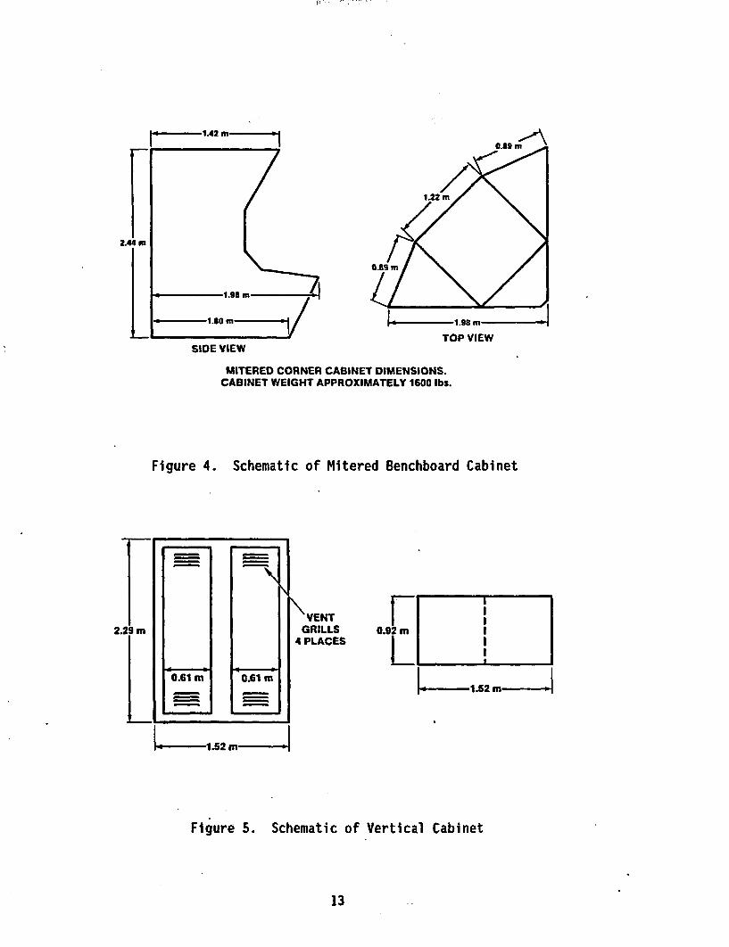
4 Schematic of Mitered Benchboard Cabinet 13
5 Schematic of Vertical Cabinet 13
6 Schematic of Benchboard Cabinet 14
7 Photograph of Transient Ignition Source 14
8 Photograph of Electrical Ignition Source 15
9 Schematic of Cabinet Instrumentation Layout 17
10 Description and Timeline for Test 21 19
11 Expected and Calculated Heat-Release Rates During Test 21 20
12 Temperatures in Noninvolved Cabinets During Test 21 21
13 Aspirated Thermocouple Measurements at Sector 2 During Test 21 22
14 Optical Density at Sector 2 During Test 21 22
15 Description and Timeline for Test 22 24
16 Expected and Calculated Heat-Release Rates During Test 22 25
17 Temperatures in Noninvolved Cabinets During Test 22 25
18 Aspirated Thermocouple Measurements at Sector 2 During Test 22 26
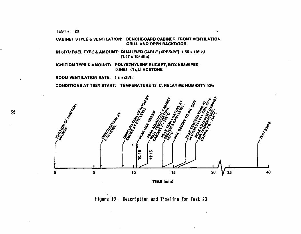
19 Description and Timeline for Test 23 28
20 Photographs of Test 23 29
21 Calculated Heat-Release Rate for Test 23 30
vi

LIST OF FIGURES (Continued)
Figure Page
22 Temperatures in Cabinet A (Subject Cabinet) During Test 23 30
23 Temperatures in Noninvolved Cabinets During Test 23 31
24 Sector 2 Air Temperatures at Each of Three ElevationsDuring Test 23 31
25 Sector 2 Optical Densities at Each of Three ElevationsDuring Test 23 32
26 Description and Timeline for Test 24 33
27 Photographs of Test 24 34
28 Calculated Heat-Release Rate for Test 24 35
29 Temperatures in Cabinet A (Subject Cabinet) During Test 24 36
30 Temperatures in Noninvolved Cabinets During Test 24 36
31 Sector 2 Air Temperatures at Each of Five ElevationsDuring Test 24 37
32 Sector 2 Optical Densities at Each of Five ElevationsDuring Test 24 37
33 Description and Timeline for Test 25 39
34 Photographs of Test 25 40
35 Heat-Release Rate for Test 25 41
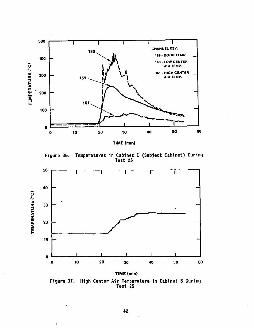
36 Temperatures in Cabinet C (Subject Cabinet) During Test 25 42
37 High Center Air Temperature in Cabinet B During Test 25 42
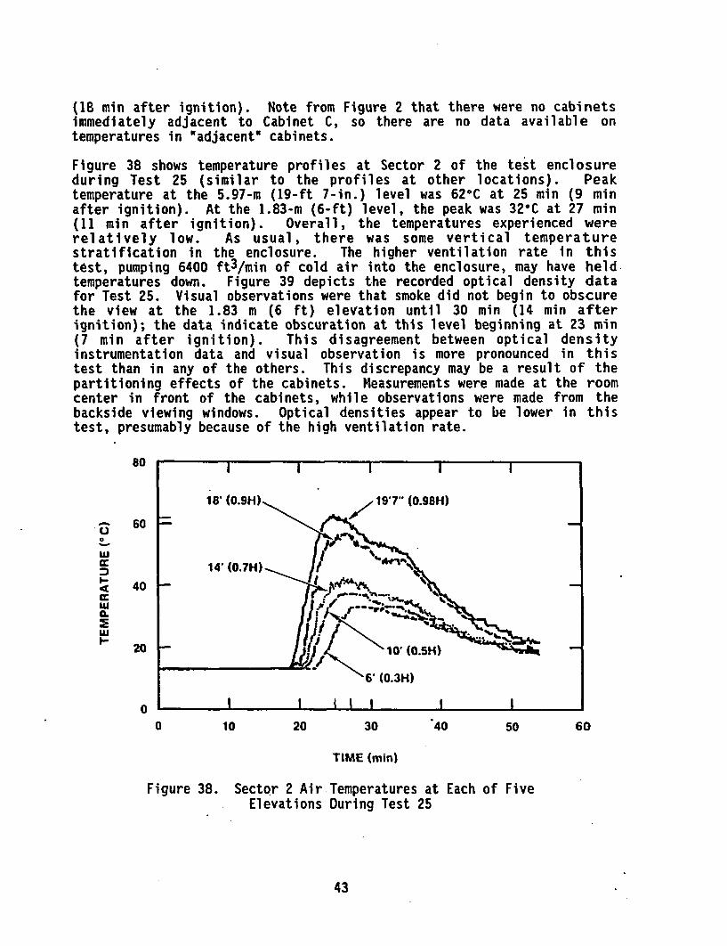
38 Sector 2 Air Temperatures at Each of Five ElevationsDuring Test 25 43
:9 Sector 2 Optical Densities at Each of Three ElevationsDuring Test 25 44
vii/viii


ACKNOWLEDGMENTS
All those individuals and groups who contributed to the successfulcompletion of this test program are gratefully acknowledged. Jeff Newmanand John Hill, both of Factory Mutual Research Corporation (FMRC), weremost directly responsible for the conduct of the tests and are singled outfor particular praise. The authors are also grateful to Mark Jacobus, ofSandia National Laboratories, Albuquerque (SNLA), for his assistance inthe setup of the tests at FMRC. Finally, the work of Barry Spletzer ofSNLA and Frank Horine of Ktech, Inc., in designing, testing, andfabricating the electrical initiation apparatus, is acknowledged.
ix/x


EXECUTIVE SUMMARY
As part of the U.S. NRC-sponsored Fire Protection Research Program, a two-part series of full-scale electrical control cabinet fire tests wasconducted by Sandia National Laboratories, Albuquerque. The first part ofthis test series, referred to as the Cabinet Effects Tests, investigatedthe effects of various cabinet parameters on fire development. The secondpart of the test series, the primary subject of this report, is referredto as the Room Effects Tests. These tests investigated the effects of acabinet fire on a very large (on the order of actual control room size)enclosure.
The cabinet fire testing was prompted by concerns on the part of the NRCstaff over the potential effects of a cabinet fire on the ability of aplant to achieve and maintain a safe shutdown state. Electrical controlcabinets, particularly control room cabinets, often represent a single-point vulnerability of multiple safety systems or components. Thuscompromising a single control cabinet by fire could potentially result inloss and/or spurious operation of multiple safety system components.Historically a number of fires have occurred in electrical cabinets (seeReference 1). While none of these incidents has involved a control roomcabinet or resulted in critical degradation of safety features, thishistorical evidence illustrates the potential for cabinet fires to occur.
In total, the two-part series of cabinet fire tests addressed four aspectsof electrical cabinet fires:
• The ability of a cabinet fire to ignite and spread
" The rate of development of a cabinet fire
" The effects of a cabinet fire on the room environment
" The potential for propagating fire and/or fire damage beyond thecabinet of origin
In addressing the final aspect, propagation of fire and fire damage beyondthe cabinet of fire origin, only a limited investigation was performed.With respect to propagation of fire, only the potential for spontaneouslyigniting an adjacent cabinet separated by a solid double-walled barrierwas investigated. The potential for spreading fire through a single-wallbarrier, or through cables that penetrate the cabinet surfaces, was notinvestigated. The results with respect to each of these aspects aredescribed below.
As a result of the two-part test series, a number of observations andconclusions were documented. With respect to the initiation anddevelopment of a cabinet fire:
• For cables that do not pass the IEEE-383 flame-spread test standard(unqualified cables), cabinet fires are easily ignited and

propagate readily, generally resulting in combustion of allcombustible materials within the cabinet. It was also demonstratedthat even a low-intensity (170-W) electrically heated fault pointcould result in full cabinet fire involvement for unqualifiedcabl es.
* For cables that pass the IEEE-383 flar--spread testing standard(qualified cables), self-sustaining fires that resulted in fullinvolvement of the cabinet were somewhat more difficult to induce.However, given the proper circumstances, such a fully involvedcabinet fire is possible, as demonstrated in Test 23.
• Peak fire intensities observed for both qualified and unqualifiedcable cabinet fires were approximately 1300 kW (Test 23, qualifiedcable, 1235 kW peak heat release rate; Test 24, unqualified cable,1300 kW peak heat release rate). These fires represent veryintense fires, which typically grew to peak intensity within 10min.
* Because of the rate of development and eventual intensity of theobserved fires, efforts to suppress these fires with hand-heldextinguishers cannot be expected to be very effective beyondapproximately 5 min after ignition. This implies that earlydetection and suppression will be the key to minimizing the effectsof a cabinet fire.
With respect to the effects of a cabinet fire on the room environment:
" Peak temperatures at ceiling level (20 ft) directly above the firesource were observed to reach as high as 262°C during a cabinetfire.
" Thermal environments in the test enclosure induced as a result of afire confined to a single cabinet, were observed to reach no higherthan 1500C peak temperatures outside the immediate fire plume.(Many plant situations exist in which groups of cabinets areventilation-isolated from the general enclosure by solid or ventedbarriers. In such situations temperatures within these areas canbe expected to exceed 1500C. However, this situation was notdirectly investigated.)
" A significant degree of vertical thermal stratification wasobserved in all tests conducted in the large (60 x 40 x 20 ft) testenclosure.
" The peak temperatures observed depend strongly on the size of theenclosure and on the ventilation rate provided throughout thecourse of the fire.
" No attempts were made under this effort to investigate the effectsof securing enclosure ventilation such as might be expected as aresponse to fire under certain fire isolation strategies.
2

" The build-up of smoke in the enclosure and the deposition of sootparticulate were observed to be significant problems in both partsof the test series. Typically, within 6-15 min smoke had totallyobscured visibility throughout the test enclosure. In the smallerenclosure used in the Cabinet Effects Tests, ventilation rates of15 room air changes per hour were typically used. For the largetest enclosure used in the Room Effects Tests, ventilation rates ashigh as 8 room air changes per hour were used. In each case theserates were insufficient to effectively purge smoke from theenclosure. In the case of the Room Effects Tests, times in excessof one hour after completion of a test, at high ventilation rates,were required to purge smoke from the enclosure. It is anticipatedthat due to this rapid build-up of a thick smoke layer, operatoreffectiveness would be severely hampered under such conditions.
With respect to the propagation of fire beyond the cabinet of fire origin:
* A solid steel, double-wall barrier was quite effective in reducingadjacent cabinet temperatures, both surface and air, below typicalspontaneous ignition temperatures for most materials. Thus thespontaneous cabinet-to-cabinet spread of fire through such barrierconfigurations is considered unlikely. This conclusion relatesonly to the actual spread of fire between cabinets. Theenvironments observed indicated that other damaging effects, smokeand high temperatures for example, may threaten electricalequipment in adjacent cabinets, even though flames may not actuallypropagate. In particular, it is anticipated that integratedcircuitry based control components will experience calibrationdrifts and/or failure at the temperatures tbserved.
" Many potential fire-spread paths were not investigated. Spreadpaths associated with cabinet partitioning barriers, which were notinvestigated, include single-wall barriers and barriers susceptibleto warping that might allow flames to pass the barrier. Based onthe results of these tests, partial or incomplete barriers andunsealed cable penetrations can be expected to allow further spreadof fire, given a fully involved cabinet fire. The vulnerability ofcables in raceways above or below a burning cabinet was also notinvestigated.
With respect to fire-induced damage to remote cables and components:
" No significant damage was observed for cable bundles located inadjacent cabinets (separated by a double-wall barrier) or in otherenclosure locations. Both visual and insulation integrity checkswere made following relevant tests.
* Heavy soot deposition throughout the enclosure was observed in mosttests. In some cases this soot was found to be heavily loaded withchlorides,[7] adding the potential for highly acidic solutions to
3
form in the presence of moisture (such as that resulting fromsuppression activities).
Low-voltage equipment present in these environments was foundgenerally to remain functional (in the absence of moisture).[7]One exception involved a strip chart recorder that jammed due todeposition of soot on mechanical parts. High-voltage equipment wasnot investigated. Also, the vulnerability of cables in racewaysdirectly above or below a burning cabinet was not investigated.
One additional insight was obtained which was not a part of the originalobjectives of the program. This involved the effectiveness of smokedetection for this type of fire. During the final cabinet test, two smokedetectors were placed in the enclosure and monitored for actuation. Onedetector was placed within the source cabinet and one in a remote cabinet.The detector in the source cabinet detected smoke from the electricalignition apparatus used in this test approximately 1 min after visiblesmoke first appeared and approximately 5 min prior to open flame ignition.The detector located in a remote cabinet did not activate until 10 'minafter fire ignition, after the fire intensity had peaked. This experienceillustrates the effectiveness of in-cabinet detection systems. Area-typedetection systems can be expected to lag in time the response of the in-cabinet detector, though the detector located in the remote cabinetprobably would represent the worst possible detector site, given thelocation of the fire.
4

1. INTRODUCTION
1.1 Background
A two-part series of full-scale cabinet fire tests was conducted as partof the Fire Protection Research Program. This program is being conductedfor the U.S. Nuclear Regulatory Commission (NRC) by Sandia NationalLaboratories, Albuquerque (SNLA). The Cabinet Fire Test Program wasprompted by the potential threat to the safety of a nuclear power plantpQsed by a cabinet fire in either a control room or a switchgear-typeroom. Although there have been no fires in control room cabinets ofoperating nuclear power plants, there haye been fires in cabinets in otherparts of plants, and these cabinet fires have resulted in significantdamage from heat, smoke, and corrosion.[]] Furthermore, based on pastprobabilistic risk analyses, a fire in a nuclear power plant representsone of the more significant potential threats to the safety of a plant,and, based on plant operating experience, a typical nuclear power plantcan expect to have three to four major fires during its lifetime.[1] Inaddition, a recent study has shown that, given the possibility of multiplespurious equipment operations (such as might be induced by a cabinetfire), remote shutdown may be rendered ineffective.[2]
Because of the perceived level of risk, the NRC staff expressed a numberof concerns about cabinet fires. These concerns centered on (a) theability of a cabinet fire to ignite and spread, (b) the rate ofdevelopment of the fire in a cabinet, (c) the resulting room environmentsproduced by the fire, and (d) the potential for the fire to spread toother cabinets and to damage equipment and components throughout the room.
The first series of NRC-sponsored tests, called the Cabinet Effects Testsand described in Volume 1 [3], investigated concerns (a), (b), and (d).The second-series of tests, described in the present volume and called theRoom Effects Tests, validated the results obtained in the first series andinvestigated concern (c).
This report will describe the general outcome of the Room Effects Tests.Only sufficient data have been processed and evaluated to interpret theresults of these tests and to permit comparison with the Cabinet EffectsTests. Further analysis of the data that are not used for this report,such as air velocities or combustion product concentrations, may beaccomplished at a later date.
1.2 Previous Studies
Previous system studies and testing have shown that cabinet fires innuclear power plants represent a potential threat to the safety andshutdown capabilities of a plant. The relevant work performed prior tothe Cabinet Fire Test Program is discussed in an earlier report associatedwith this effort.[3]
5
Based on the Cabinet Effects Tests, a number of conclusions were reached,as follows.
" Cabinet fires can be ignited and can propagate in either IEEE-383-qualified or -unqualified cable, with either of the ignitionsources tested (transientl and electrical). However, ignition andpropagation are less likely to occur in IEEE-383-qualified cable.
* A cabinet fire, with either IEEE-383-qualified or -unqualifiedcable as the in situ fuel, in either a vertical or benchboard-stylecabinet, can develop rapidly (in minutes). However, in tests withqualified cable, the fires did not become as large as thoseinvolving unqualified cables. (This observation has been modifiedas a result of the room effects tests in that one particular testusing qualified cable resulted in a fire as intense as any observedwith unqualified cable).
Ignition, development rate, and spread of a cabinet fire depend oncritical combinations of many interdependent variables (ignitionsource, in situ fuel geometry and amount, cabinet style,ventilation, etc.). Hence, the course of any given cabinet fire issubstantially unpredictable unless, as is unlikely, the values ofall these variables are known in advance. Even then, it would bedifficult to predict the exact course of the fire.
* For the enclosure conditions tested in the Cabinet Effects Testseries (enclosure size and ventilation rate), the thermalenvironment produced by the fires in the-enclosure was not severeenough to cause autoignition of remote materials, but the thermalenvironment may have been severe enough to cause equipment damage.Furthermore, it appears from these tests that a cabinet fire willnot spread from the burning cabinet to adjacent cabinets. However,under different conditions (e.g., a single wall, larger fires), acabinet fire could potentially cause autoignition in adjacentcabinets and continue to propagate. Based on measurements ofbarrier surface temperatures, the double-wall barrier betweencabinets used in these tests appears to have played a crucial rolein preventing cabinet-to-cabinet fire spread during the largercabinet fires. The effects of cable penetrations in the cabinetsurface and the potential for spread of fire through suchpenetrations were not investigated.
* For the enclosure conditions tested, dense smoke accumulation inthe room became a problem within minutes after ignition, for allfuel types and cabinet configurations.
Essentially, the general conclusion at the end of the Cabinet EffectsTests (Volume 1) was that a cabinet fire can propagate within a single
1.consisting of a plastic bucket, paper, and 1 qt of acetone
6

cabinet; however, for the conditions tested, it does not appear that thefire'poses a threat outside the burning cabinet (except for the smoke).Other cabinet and fuel configurations may result in a completely differentoutcome.
Although these conclusions are significant, the tests on which they arebased have not been replicated or validated except as described hereafterin the present volume. The most significant data to be obtained from theRoom Effects Tests (Part II as described in this document) are the effectsof smoke on the control-room-size enclosure. It is also of interest tonote that one particular test in this second series (designated Test 23)resulted in a qualified cable cabinet fire whose intensity exceeded thatof any fire experienced during any previous qualified cable cabinet firetest. This particular test provides a graphic demonstration of theinherent variability of fires and the potential pitfalls ofover-generalizing the results of a limited series of fire tests.
7
2. MATERIALS AND METHODS
2.1 Test Facility and Instrumentation
The enclosure used for the tests described here is located at the FactoryMutual Research Center (FMRC) test site in Rhode Island. The entire testenclosure is itself housed within an outer building and thus isolated fromthe external environment. The enclosure, shown in Figure 1, is 18.3 mlong, 12.2 m wide, and 6.1 m high (60 ft x 40 ft x 20 ft). The interiorsurfaces of the enclosure's ceiling and walls are lined with 2.5-cm-(1-in.-) thick Marinite 2 I panels to simulate the concrete ,dalls encounteredin nuclear power plants. The concrete slab that makes up the foundationof the test building served as the floor of the enclosure. A forced-ventilation system with six inlet ports and one outlet port providedventilation rates of from 1 to 10 room air changes per hour. A detaileddescription of the test enclosure is provided in Reference 4.
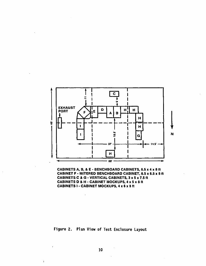
The control room mockup, presented schematically in Figure 2, included six"real" electrical control cabinets (three benchboard style, one mitered-corner benchboard style, and two single-bay vertical style). Theremainder of the mockup was constructed of Marinite I panels bolted tometal framing material. The overall height of the mockup was 2.4 m (8ft). Figure 2 gives the actual dimensions of each section of the controlroom mockup.
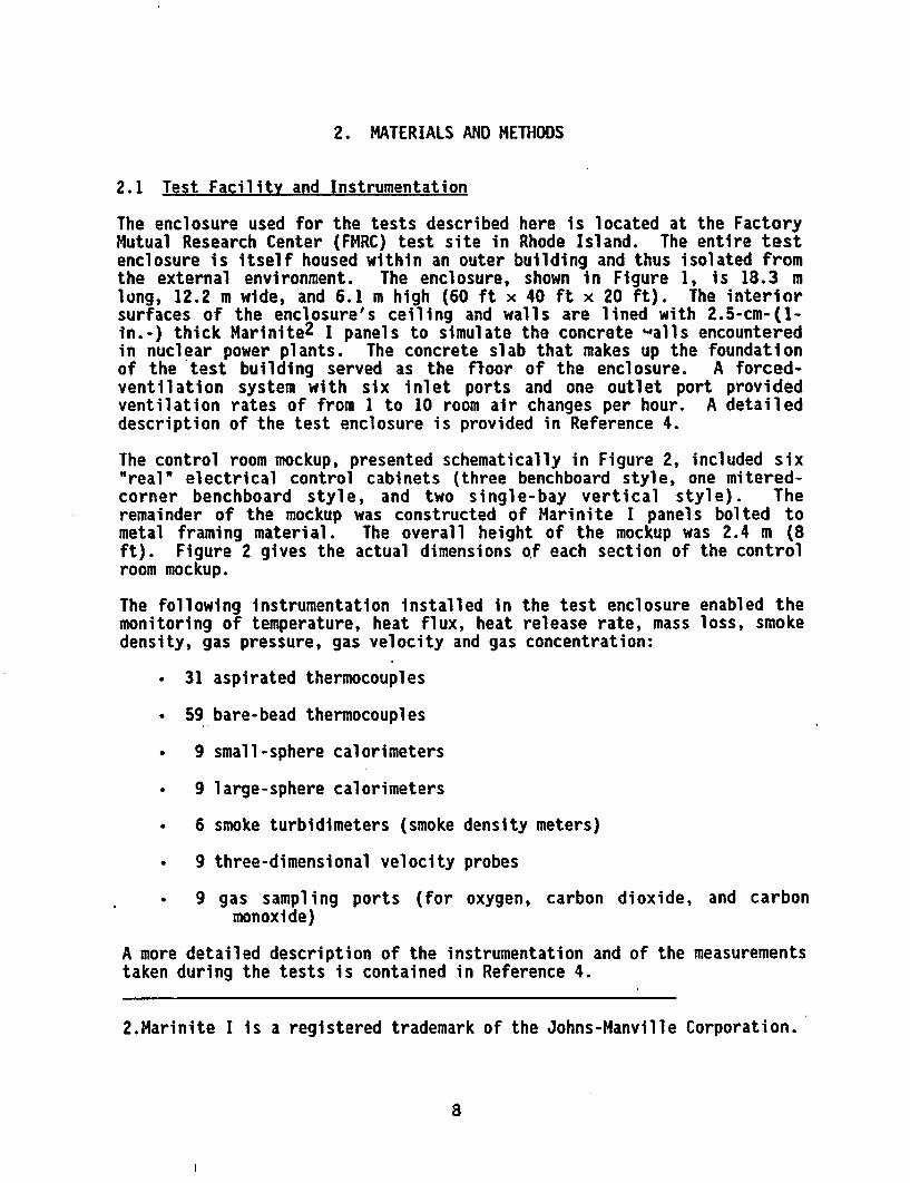
The following instrumentation installed in the test enclosure enabled themonitoring of temperature, heat flux, heat release rate, mass loss, smokedensity, gas pressure, gas velocity and gas concentration:
* 31 aspirated thermocouples
* 59 bare-bead thermocouples
* 9 small-sphere calorimeters
0 9 large-sphere calorimeters
* 6 smoke turbidimeters (smoke density meters)
a 9 three-dimensional velocity probes
* 9 gas sampling ports (for oxygen, carbon dioxide, and carbonmonoxide)
A more detailed description of the instrumentation and of the measurementstaken during the tests is contained in Reference 4.
2.Marinite I is a registered trademark of the Johns-Manville Corporation.
8

w
14~E
ACCESSDOOR
INSTRUMENTATIONTRAILER LOCATION
OBSERVATIONWINDOW
OBSERVATION ACCESSWINDOWS DOOR EXTERIOR FRAMEWORK.
50 mm x 150 mm LUMBER (2" x 6")SPACED 0.61 m ON CENTERDIMENSIONS IN UNITS
OF METERS
Figure I. Three-Dimensional View of Test Enclosure
9
'IFN
6W
CABINETS A, B, & E - BENCHBOARD CABINETS, 6.5 x 4 x 8 ItCABINET F - MITERED BENCHBOARD CABINET, 6.5 x 6.5 x8 ItCABINETS C & G - VERTICAL CABINETS, 3 x 5 x 7.5 ItCABINETS D & H - CABINET MOCKUPS, 4 x 5 x 8 ItCABINETS I - CABINET MOCKUPS, 4 x 6 x 8 ft
Figure 2. Plan View of Test Enclosure Layout
10

2.2 Test Materials and Arrangements
2.2.1 Control Room Mockup
The control room mockup, photographs of which are shown in Figure 3, wasused to simulate the effects of cabinet arrangement on the development ofa cabinet fire in the control-room-size test enclosure. The mockup didnot represent any particular control room, but its dimensions andarrangement were based on a survey of plant control rooms, and itsconfiguration is generic.[3,5]
2.2.2 Cabinets
All the vertical cabinets used in the control room mockup were surpluscabinets obtained from a nuclear power plant vendor, while the benchboardcabinets were constructed specifically for this test program tospecifications typically used for nuclear power plant cabinets.[3,5]Figures 4 through 6 provide dimensional data on the primary cabinets thatwere used in the testing.
2.2.3 Ignition Sources
Two ignition sources were used in the tests, one transient and oneelectrical. The transient ignition source was made up of a 9.5-1 (2.5-gal) polyethylene bucket, with an open 0.5-kg (16-oz) box of Klmwipes, 3
and 0.946-1 (1 qt) of acetone placed in the bucket. One half of theacetone. was poured into the bottom of the bucket, the bottle and remainderof the acetone were placed in the bucket, and the cap was left off theplastic bottle to simulate the bottle spilling. Also, 15 Kimwipes wereballed up and put in the bottom of the bucket. This ignition source,shown in Figure 7, was ignited by an electrically ignited gas pilot lightsetting fire to one of the Klmwipes hanging out of the bucket. Thisignition source burns at an intensity of w40 kW. (This source can becompared to the peak fire intensities of 1300 kW observed during testing.)A more detailed description of this ignition source is provided inReferences 3 and 5. The electrical ignition source consisted of aterminal strip and 25 pieces of stripped (unjacketed) cables, shown inFigure 8. This source was ignited by providing w165 W of power to theterminal strip, resulting in overheating at the connection and culminatingin a fire. The selection and use of these ignition sources are describedin more detail in References 3 and 6.
3.Kimwipe is a registered trademark of the Kimberley-Clark Corporation.
11

Figure 3. Photographs of Control Room Mockup
TOP VIEWSIDE VIEW
MITERED CORNER CABINET DIMENSIONS.CABINET WEIGHT APPROXIMATELY 1600 Ibs.
Figure 4. Schematic of Mitered Benchboard Cabinet
AVENTGRILLS
4 PLACES
.0.92 m (I
I
L
1.52 m
Figure 5. Schematic of Vertical Cabinet
13

.- 1.9a M
1.22mI
Ii .
I~ II I II I II I II I II ! Im i
TOP VIEW
SIDE VIEW
BENCHBOARD CABINET DIMENSIONS.WEIGHT OF CABINET APPROXIMATELY 1300 lbs.
Figure 6. Schematic of Benchboard Cabinet
Figure 7. Photograph of Transient Ignition Source
14

Figure 8. Photograph of Electrical Ignition Source
2.2.4 In Situ Fuels
The in situ fuels were the primary source of fuel in the cabinets.[5] Itwas considered reasonable to represent all the fuels in the cabinets withcables, which are the largest source of in situ fuels in cabinets. Mostplants use IEEE-383-qualified cable; however, some (420%)[5] operatingplants still use unqualified cable in their control cabinets. Becauseboth types of cable are still found in plants, both types of cable wereused in the testing.
The IEEE-383 qualified cable, called qualified cable in the text anddesignated as "Q" cable in the plots and tables, was three-conductor, No.12 AWG, with 0.76-mm (30-mil) cross-linked polyethylene (XPE) insulation,silicon glass tape, and a 1.65-mm (65-mil) cross-linked polyethylene (XPE)jacket, rated at 600 V. The unqualified cable, designated as "UQ" cablein the plots and tables, was three-conductor, No. 12 AWG, with 20/10polyethylene/polyvinylchloride (PE/PVC) insulation, and a 45-mil (1.14-mm)polyvinylchloride (PVC) jacket.
The fuel loadings and their arrangements in the cabinets were designed tobe generic to nuclear power plant (NPP) cabinets *(as described inReference 3), in order to make the applicability of the tests as wide aspossible. The fuel configurations used in these tests were as similar aspossible to those in the Cabinet Effects Tests.[3]
15

Cable bundles, similar to those used to make up the in situ fuel load inthe burning cabinet, were placed at eight other locations in theenclosure. One bundle was placed on each adjacent wall in the adjacentcabinet, and one bundle on each opposite wall in the adjacent cabinet.The remaining four bundles were placed on top of various cabinets andcabinet mockups around the enclosure. The purpose of placing these cablebundles was to investigate the room environment effects on the cables.
2.3 Cabinet Instrumentation
In addition to the instrumentation installed in the test enclosure,described in Section 2.1 and detailed by Nowlen in Reference 5, thecabinets in the control room mockup were themselves instrumented withfree-air or surface-mounted thermocouples, heat flux gages, andbidirectional pressure flow probes. The general arrangement of thisinstrumentation is shown in Figure 9. A few other cabinets were lightlyinstrumented with thermocouples; however, only the cabinets shown inFigure 9 were heavily instrumented because they were in the generallocation of the fires.
16

VERTICAL CABINET'C'
TC21. 22
x
TC2O /V\ HF2
TC7 )A HF4
AIR THERMOCOUPLESURFACE THERMOCOUPLE
HEAT FLUX
BI-DIRECTIONAL PRESSURE
Figure 9. Schematic of Cabinet Instrumentation Layout
17

3. DISCUSSION OF CABINET AND CONTROL ROOM FIRE TESTS
Five cabinet and control room fire tests, identified hereafter simply asTest 21 through Test 25, were conducted at the FMRC test facility. (Notethat Tests 1-20 involved simple fuel sources and are described inReference 4.) Table I summarizes the test setup for Tests 21 through 25.
Table 1
Cabinet and Control Room Tests 21Test Setup Summary
Through 25
TestParameter 21 22 23 24 25
Location of FireBenchboard Cabinet A X X X XVertical Cabinet C X
Ignition SourceGas Burner X XTransient Source XElectrical Source x x
In Situ FuelPropylene X XQualified Cable XUnqualified Cable X X
Ventilation RateI Room Change/hr X X X X8 Room Changes/hr X
3.1 Gas Burner Tests in Benchboard Cabinets (Tests 21 and 22)
JTest 21 used a 0.91-m- (3-ft-) diameter propylene sand burner in thebenchboard Cabinet A. 4 This test was also reported on briefly byNowlen.[4] A description of the test and a timeline of the events thatoccurred during the test are provided in Figure 10. The purpose of thistest was primarily to provide data with a known heat source and rate touse in validating enclosure instrumentation, previous fire tests (Cabinet
4.Note that tests 21-25 followed a series of 20 enclosure fire tests inthe large-scale test facility, hence, high test numbers
18

TEST #: 21 PROPYLENE BURNER IN CABINET "A", GROWING FIRE TO 516 kW IN240 SECONDS
CABINET STYLE & VENTILATION: BENCHBOARD CABINET, FRONT VENTILATIONGRILL AND OPEN BACKDOOR
ROOM VENTILATION RATE: 1 rm ch/hr
Az
A.;, A?
4k A.'0 ( It 40 'Q
.1b ~~~ 4V . 4 4 V* t.0 q* *A
.40~ A40 C&Z~r P7 b*0 -ZF_________ ___i;iif0 5 10 15 20 25
TIME (min)
Figure 10. Description and Timeline for Test 21

Effects Tests), and fire models. However, the data are also useful forinvestigating the effects of a cabinet fire on an enclosure. The roomventilation rate of one room change per hour (rm ch/hr) is typical of manynuclear power plant control rooms. The expected actual heat release rate(HRR) and calculated HRR are shown in Figure 11.
The calculated HRR, evaluated using the method described by Nowlen,[4] isnot steady because of variation in the ventilation flow rate and otherfactors. The calculated values do, however, follow the general behaviorand magnitude of the HRR profile, which was based on gas flow rate.
The interior of Cabinet A was essentially at flame temperature because ofthe large flames produced by the burner. Adjacent cabinet temperaturesare shown in Figure 12. Cabinet B, the adjacent benchboard cabinet, had apeak wall temperature at TC #155 of 2350C and was still rising when theburners were shut off. This temperature could potentially damage cableson the wall but would not have ignited them. Air temperatures in CabinetsB, C, and D were all less than 1000C when the burners were shut off.
i
I
700
600
500
400
300
200
100
00 5 10 15 20 25 30
TIME (min)
Figure 11. Expected and Calculated Heat-Release RatesDuring Test 21
20

The enclosure environment is depicted by Figures 13 and 14, the enclosuretemperatures and enclosure optical density. The enclosure temperatures atSector 25 did not rise over 1O00C, although they were still rising whenthe burners were turned off. The vertical temperature stratification inthe enclosure was not significant in a 0.305- to 1.82-m (1- to 6-ft) range(but it was significant when the total room height was considered). Also,as shown in Figure 13, there was no obvious hot layer, using the typicaldefinition of a "hot layer" as a sudden, large (>100"C/m) temperaturejump. The smoke obscured the view inside the enclosure within 10 minafter ignition. The smoke layer could be seen descending from the ceilingduring the test, as shown in Figure 14. The smoke was always denser nearthe upper part of the enclosure. However, even at the 1.82-m (6-ft)elevation, the optical density (Figure 14) was indicative of very poorvisibility conditions that developed quite quickly.
400
0i
ccI
I.-CLVJtoo
300
200
100
00 5 10 15 20 25 30
TIME (min)
Figure 12. Temperatures in Noninvolved Cabinets During Test 21
5."Sector 2" is a designation used to identify the instrument tree locatedat the physical center of the test enclosure (see Reference 4).
21

w
IL
100
80 -
60 -
40
20
0-0
Figure 13.
14
12
S10
.1 6
L4
2
0
5 10 15 20 25 30
TIME (min)
Aspirated Thermocouple Measurements at Sector 2During Test 21
d
¢
0 5 10 15 20
TIME (min)
Figure 14. Optical Density at Sector 2
25 30
During Test 21
22
This test demonstrated that with a gaseous fuel (propylene), a firegrowing to a peak rate of 516 kW results in only a moderate rise inenclosure temperature. The observed enclosure peak temperature outsidethe fire plume of less than 1O00C would not generally be assumed to resultin problems for most equipment, with the possible exception of integratedcircuits. The smoke accumulation in the enclosure obscures the viewinside the enclosure within 10 min and is potentially a major problem.Previous testing at FMRC has indicated that the smoke-generating proper-ties of propylene are quite similar to those of many types of cableinsulation so that similar enclosure effects were expected for the firesof similar magnitude involving cable insulation.
Test 22 employed the same setup as Test 21 except that the burner wasprogrammed to grow to 1000 kW in 8 min. This test was also designed toprovide data for computer code, enclosure instrumentation, and previoustest (Cabinet Effects Tests) validation. A description of the test and atimeline of the events that occurred in the test are provided in Figure15. The expected profile and calculated heat-release rates -are shown inFigure 16. It should be noted that in this test, the propylene fuelinventory was insufficient to maintain the desired gas flow rate. Atapproximately 12 min after ignition, test personnel observed that gaspressure had fallen from the initial value of 175 kPa to 133 kPa (25 psigto 19 psig). Further observation of the gas pressure indicated that gaspressure decreased steadily throughout the remainder of the burn. At thetime of scheduled burner shutdown, a pressure of approximately 91 kPa (13psig) was reached. Thus, the calculated HRR shown in Figure 16 accuratelyreflects the actual fire behavior observed.
Temperatures in the adjacent cabinets are shown in Figure 17. The peakwall temperature in Cabinet B is higher than in Test 21 at 3600C. Thetemperature appears to have peaked before the, burners were turned off.This is most likely a result of the failure to maintain the desired gasflow over the course of the test. Temperatures in this range would not beexpected to result in autoignition of either qualified or unqualifiedcable, although damage to cables or components is likely to occur at thesetemperatures. Again, as in Test 21, the adjacent cabinet air temperatureswere all less than 1O00C, with the air in Cabinet B reaching a maximum of806C at 14:30 min after ignition.
The peak enclosure temperature in this tests was 1070C near (5.97 m [19 ft7 in]) the ceiling at Sector 2 (the room center location). As in Test 21,the temperatures were stratified vertically with a peak temperature at the0.3 x H level, 1.83 m (6 ft), of 620C. These temperatures are shown inFigure 18 for Sector 2. The smoke layer descended from the ceiling at asteady rate, eventually obscuring the view inside the room within 10 min.
3.2 Benchboard Cabinet Fire Tests*(Tests 23 and 24)
Test 23 was the first Room Effects Test in which a "real" fuel was burned.IEEE-383-74 qualified cable (XPE/XPE) was placed inside a benchboard-style
23

TEST 0: 22 PROPYLENE BURNER IN CABINET "A", GROWING FIRE TO 1000 kW IN480 SECONDS
CABINET STYLE & VENTILATION: BENCHBOARD CABINET, FRONT VENTILATIONGRILL AND OPEN BACKDOOR
ROOM VENTILATION RATE: 1 rm ch/hr
TV
co;0
A,'(01
0 5 10 15 20
TIME (raln)
Figure 15. Description and Timeline for Test 22

X.
1200
1000
800
600
400
200
0
0 5 10 15 20 25 30
TIME (min)
Figure 16. Expected and Calculated Heat-Release RatesDuring Test 22
400I I I
aw
U.1c-
0.wI-
300
200
100
(Ii
I'I'I/ 1/III
4-,
---.
1 _ I
CHANNEL KEY:
152 - CAB 'D' CENTER AIR
155 - CAB 'B' HIGH RIGHT WALL
157 - CAB 'B' HIGH CENTER AIR
161 - CAB 'C' HIGH CENTER AIR
155
/ /157
/161,,152
0 I
0 5 10 15 20 25 30
TIME (min)
Figure 17. Temperatures in Noninvolved-Cabinets DuringTest 22
25

120
100 - 197, (0.98H)
j3 18 (0.9H) ,,o 80 - f " ... "y,//, -....
< 60 -.- .. ..--...
40' 14' (O.7H)I- /
4,// / 10' (0.5 H)20 -. : 6' • (0. 3H)
0 I I I I0 5 10 15 20 25 30
TIME (min)
Figure 18. Aspirated Thermocouple Measurements at Sector 2During Test 22
cabinet and used to make up the in situ fuel configuration. Theconfiguration was arranged as nearly identical as possible to theconfiguration in Preliminary Cabinet Test 5.[3] The in situ fuel loadingfor Test 23 was 1.55x10 6 kJ (t1.47x10 6 Btu). Ignition source for thistest was the transient source (i.e., a bucket, a box of Kimwipes, and0.9 A (1 qt) of acetone). The cabinet was provided with a bottom frontventilation grill, and the door in the rear remained open during the test.Room ventilation was set at 1 rm ch/hr (0.38 m3 /s or 800 ft 3/min).
After ignition, the fire began to propagate rapidly up the ignition bundleand quickly spread throughout the cabinet. Unlike any previous cabinettest performed at SNLA with qualified (XPE/XPE) cable, the fire spreadthroughout the entire cabinet, consuming all the cable. This isattributed to two potential factors. First, as fires are inherentlydifficult to reproduce it has been conjectured that the cables werearranged in a "critical" configuration due to seemingly minor differences.It also appears that the soffit above the open cabinet door led to theformation of a "mini" hot layer within the cabinet that enhanced thethermal feedback to the cables, thus accounting for the much higherintensity than that observed with qualified cable in a vertical cabinetwith no such doorway soffit. This event illustrates the influence of theso-called critical configuration described in the Cabinet EffectsTests. [3]
26
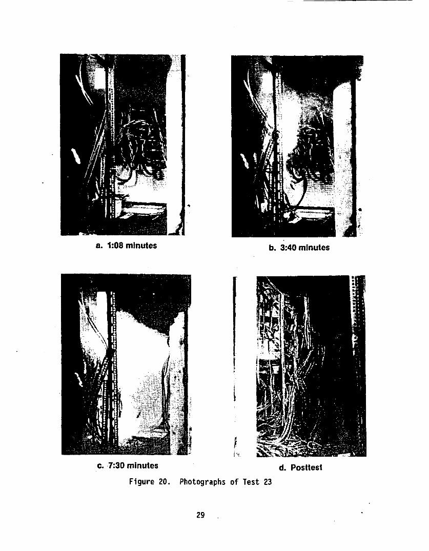
A description of Test 23 and a timeline showing the events that occurredduring the test are provided in Figure 19. Figure 20 is a sequence ofphotographs taken during the test. The heat-release rate (HRR) in thistest rose rapidly in 1O min to a peak of 1235 kW, then dropped off withinanother 10 min, as shown in Figure 21. This fire was the most intensefire encountered up to this point in the test effort. This fire intensityexceeded that observed in any of the cabinet effects tests, with eitherqualified or unqualified cables. Only Test 24 of this series, involvingunqualified cable in an identical configuration and described below,resulted in a more intense fire.
The air inside the burning cabinet, as shown in Figure 22, was effectivelyat flame temperature until the fire began to burn down at around 20minutes. However, the upper left wall temperature (TC 145) stayed ataround 700 0C until well after observable fire activity ceased. Thecontinuing high temperature was most likely due to a hot spot caused bysmoldering cables. Adjacent cabinet air and wall temperatures are shownin Figure 23. The peak adjacent cabinet wall temperature was 2720C at11:15 min after ignition. As shown in Figure 23 at 11:15 min, the walltemperature dropped sharply to approximately cabinet air temperature (TC147). The reason for the sharp drop in temperature appears to be becausethe thermocouple on the wall (TC 155) came loose from its attachment tothe wall. The adjacent cabinet wall temperature would have gone higher,but how high is unknown. The peak cabinet.air temperature was 114°C inCabinet B at 16:30 min after ignition. Total cable weight burned duringthis test was 49.55 kg (109 lb).
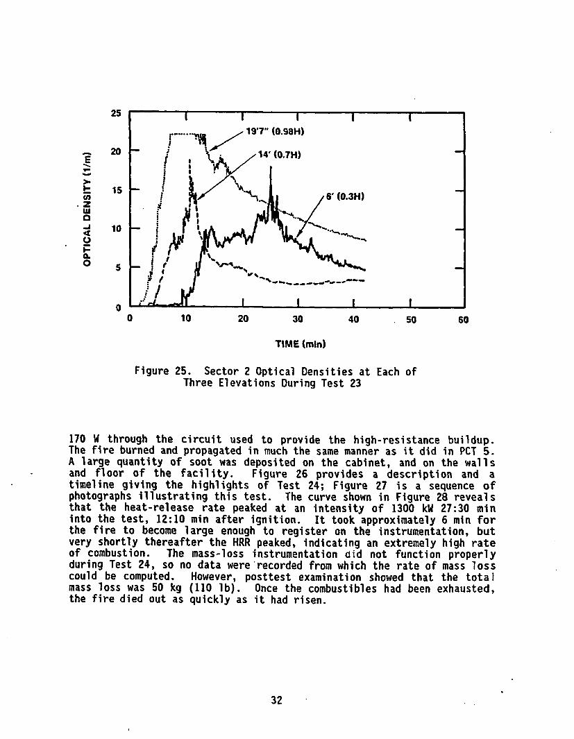
The enclosure temperatures for Sector 2 (temperatures at other locationsare very similar) are shown in Figure 24. The peak temperature, 1326C, inthe enclosure at Sector 2 was at the 5.97-m (19-ft 7-in) level at 13:15min after ignition. As shown in Figure 24, there is some verticaltemperature stratification in the enclosure. The peak temperature at the1.83-m (6-ft) level was 871C at 15:30 after ignition. During the test,the smokebegan to obscure the view at the 1.83-m level at 9 minutes. Theoptical densities at Sector 2 for three different levels are shown inFigure 25. The vision distance with a bright light at an optical densityof 2 m-I is w0.86 m. (Unit of optical density is reciprocal meters, i.e.,meters to. the -1 power, although conversion to visibility distances is nota linear operation.[4]) An observation made after the test was that therewas a thick deposit of soot on the cabinets and floor. Also, it took along time (1 hr) to purge the smoke from the enclosure after the test.Cable bundles in other cabinets, on top of other cabinets, and in otherlocations throughout the enclosure did not experience any damage.
In Test 24, unqualified cable (PE/PVC) was placed inside a benchboardcabinet. The in situ fuel configuration for this test was the same as forPCT 5 of the Cabinet Effects Tests. As in PCT 5, the ignition source waselectrical, provided by a simulated high-resistance buildup. Again thefuel loading was 1.47x40 6 kJ (1l.44xO1 Btu). The room ventilation wasmaintained at I rm ch/hr. Ignition of the cables occurred at a power of
27
TEST #: 23
CABINET STYLE & VENTILATION: BENCHBOARD CABINET, FRONT VENTILATIONGRILL AND OPEN BACKDOOR
IN SITU FUEL TYPE & AMOUNT: QUALIFIED CABLE (XPE/XPE), 1.55 x 101 kJ(1.47 x 10⁶ Btu)
IGNITION TYPE & AMOUNT: POLYETHYLENE BUCKET, BOX KIMWIPES,0.9461 (1 qt.) ACETONE
ROOM VENTILATION RATE: 1 rm ch/hr
CONDITIONS AT TEST START: TEMPERATURE 130C, RELATIVE HUMIDITY 43%
0
0 5 10 15
TIME (min)
20 V 35 40
Figure 19. Description and Timeline for Test 23
Ja. 1:08 minutes b. 3:40 minutes
I
Ic. 7:30 minutes
Figure 20. Photographsd. Posttest
of Test 23
29

2000
1500
i1000
500
0
1000
800
0 10 20 30 40 50 60
TIME (min)
Figure 21. Calculated Heat-Release Rate for Test 23
0
Uiwcc
4
I-•L
Ui
600
400
200
00 10 20 30 40 50 60
TIME (min)
Figure 22. Temperatures in Cabinet A (Subject Cabinet)During Test 23
30

w4
wIL
2rw-
300
250
200
150
100
50
00 10 20 30 40 50 60
TIME (min)
Figure 23. Temperatures in Noninvolved Cabinets DuringTest 23
'a
4
'a0.
'aI-.
200
150
100
50
00 10 20 30 40 50 60
TIME (min)
Figure 24. Sector 2 Air Temperatures at Each ofFive Elevations During Test 23
31
25
20 V. 14' (0.7H)
is
15 6' (0.3H)tu
101
10
0.
0 10 20 30 40 50 60
TIME (min)
Figure 25. Sector 2 Optical Densities at Each of
Three Elevations During Test 23
170 W through the circuit used to provide the high-resistance buildup.The fire burned and propagated in much the same manner as it did in PCT 5.A large quantity of soot was deposited on the cabinet, and on the wallsand floor of the facility. Figure 26 provides a description and atimeline giving the highlights of Test 24; Figure 27 is a sequence ofphotographs illustrating this test. The curve shown in Figure 28 revealsthat the heat-release rate peaked at an intensity of 1300 kW 27:30 mininto the test, 12:10 min after ignition. It took approximately 6 min forthe fire to become large enough to register on the instrumentation, butvery shortly thereafter the HRR peaked, indicating an extremely high rateof combustion. The mass-loss instrumentation did not function properlyduring Test 24, so no data were'recorded from which the rate of mass losscould be computed. However, posttest examination showed that the totalmass loss was 50 kg (110 lb). Once the combustibles had been exhausted,the fire died out as quickly as it had risen.
32

TEST #: 24
CABINET STYLE & VENTILATION: BENCHBOARD CABINET, FRONT VENTILATIONGRILL AND OPEN BACKDOOR
IN SITU FUEL TYPE & AMOUNT: UNQUALIFIED CABLE (PE/PVC), 1.47 x 10⁶ kJ(1.44 x 10⁶ Btu)
IGNITION TYPE & AMOUNT: ELECTRICAL, IGNITION SOURCE
ROOM VENTILATION RATE: I rm ch/hr
II~%&liiwqrlfie AT TArrC OTAlT, i A J E ofr Da AQEiter ail mlrief •da0%WJfhI tv ~ F~Dm I * pI&fq I Uri~ r LU %& n r.
0
1 z;'-lA..
0 c#Af ~4U
0. Q
4 ,
0,~c
M I IVC r1UMSI I T f(170 ~
4-b
41f 114
it1 a? Q 0C C 1 0
0.r 4f.k g It A1t A)
0o9-
a I I# S- k~dI
0 5 10 15 20 25 30 35 54
TIME (min)
Figure 26. Description and Timeline for Test 24

0I
a
4a. 2:15 minutes b. 8:00 minutes
c. 9:00 minutes d. Posttest
Figure 27. Photographs of Test 24.(All times are after ignition)
34

1400
1200 -
1000
800 -
Gc 600
400
200 -
00 10 20 30 40 50 60
TIME (min)
Figure 28. Calculated Heat-Release Rate for Test 24
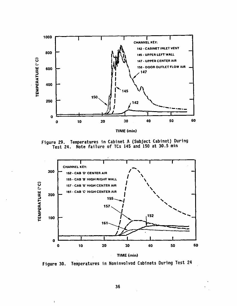
Figure 29 is a plot of temperatures inside Cabinet A during Test 24. Itshows that the cabinet's interior essentially reached the flametemperature once the fire began to spread. Flames were, in fact, observedcoming out of the cabinet pear the top of the door. There appeared to becombustion of the gases in the top of the cabinet. Figure 30 is a plot oftemperatures inside Cabinet B, the adjacent cabinet, during Test 24. Thepeak temperature in Cabinet B reached only 900C at 34 min, but the rightcabinet wall recorded a temperature of 3190C at 32:30 min (18:40 and 17:10postignition, respectively).
Figure 31 is a plot of air temperatures at Sector 2 of the test enclosure(temperatures at other locations were similar to those at Sector 2). Atthe 5.97-m (19-ft 7-in) elevation, the peak of 1210C was reached at 29:45min; at 1.83 m (6 ft) above the floor, the highest temperature recordedwas 75"C at 32:16 min (14:25 and 16:54 postignition, respectively). Somevertical temperature stratification is apparent, but not as much as inTest 23 with qualified cable. The temperatures seen in Test 24 are belowdamage levels for most equipment and cables, with the possible exceptionof integrated circuits. Figure 32 indicates the gradual descent of thesmoke layer as the test progressed. Smoke completely obscured the view
35
w
0.1
CLI-
1000
800
600
400
200
00 10 20 30 40 50 60
TIME (min)
Figure 29. Temperatures inTest 24. Note failure
Cabinet A (Subject Cabinet) Duringof TCs 145 and 150 at 30.5 min
300 1-
0
LuU.JM 200I-
4LuU.
Lu 100
I IIICHANNEL KEY:
152 - CAB 'D CENTER AIR
155 - CAB '" HIGH RIGHT WALL
157 - CAB B' HIGH CENTER AIR
161 - CAB 'C" HIGH CENTER AIR
155",I
157 1
00 10 20 30 40 50 60
TIME (min)
Figure 30. Temperatures in Noninvolved Cabinets During Test 24
36

200
0
wUc-
4i
150
100
50
00 10 20 30 40 50 60
TIME (min)
L-
zw0C.)
20.
0
Figure 31.
30
25 -
20 -
15
10
5 "-
O _ _
Sector 2 Air Temperatures at Each of FiveElevations During Test 24
0 10 20 30 40 50 60
Figure 32.
TIME (min)
Sector 2 Optical Densities at Each Of ThreeElevations During Test 24
37

from the front of the enclosure of the 1.8-m (6-ft) level beginningapproximately at 15 min after ignition. This visual observation issomewhat at variance with the plot, which shows an optical density of I m-I at 27 min, or 12 min after ignition, shortly prior to the time at whichsmoke was visually observed to obscure vision.
Significantly more soot was observed to have been deposited on the floorand cabinets than had been seen in Test 23 or in any of the CabinetEffects Tests. There are three likely causes, which may have operatedseparately or in combination to produce this result: (1) the recordedrelative humidity of 71% (this parameter never reached that value in theCabinet Effects Tests), (2) the use of unqualified cable as the in situfuel; or (3) the low ventilation rate (I rm ch/hr) compared to the CabinetEffects Tests. This discussion is carried further by Jacobus in Reference7. As in Test 23, no damage to cables outside the burning cabinet wasobserved.
3.3 Vertical Cabinet Fire Test (Test 25)
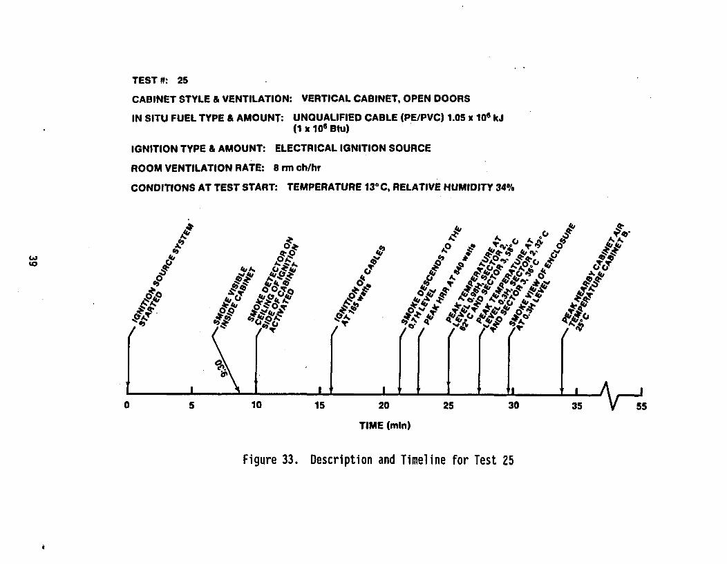
The last test performed was Test 25, in which unqualified cable (PE/PVC)was burned inside a vertical cabinet. The in situ fuel arrangement andamount were approximately the same as in PCT 2.[3] Approximately1.05xIO6 kJ (I.Ox10 6 Btu) of cable insulation was loaded into the verticalcabinet. The doors to the cabinet were left open throughout the test.Ignition was induced by simulated electrical high-resistance heat buildup(in PCT 2, the equivalent test from Part 1 of the test series, a transientignition source was used). Room ventilation was maintained at an exchangerate of 8 rm ch/hr (6400 ft 3 /min) to investinate the effect of highventilation rates. The fire propagated in much tLa same way it did in PCT2, consuming most of the cables except a few near the floor of thecabinet.
Figure 33 is a description and timeline, showing significant events duringTest 25. Figure 34 is a sequence of photographs taken during the test(times shown are after ignition). The heat-release-rate curve shown inFigure 35 shows an 840 kW peak at 22 min into the test, 6:20 min afterignition. This is compared to the approximate peak HRR of 995 kW seen at12 min after ignition in PCT 2. The fire appears to have spread much morequickly in this test than it did in Test 24, when peak HRR was not reacheduntil 12 min after electrical ignition. The fire grew very quickly yetdied down slowly, compared with Tests 23 and 24. The most probable causesof this difference in fire behavior were that in Test 25, the fuel wasmore widely dispersed horizontally, and there were fewer vertical cableruns in the cabinet; thus, it reached a lower peak HRR sooner and burnedat a lower rate for a longer period.
In this test, a smoke detector was mounted on the ceiling of the cabinetdirectly above'the electricaT ignition source. A second detector was alsoplaced on the ceiling of remote cabinet "F", as shown in Figure 2. Thepurpose of the smoke detector was to determine when a typical in-cabinet
38
TEST #: 25
CABINET STYLE & VENTILATION: VERTICAL CABINET, OPEN DOORS
IN SITU FUEL TYPE & AMOUNT: UNQUALIFIED CABLE (PE/PVC) 1.05 x 10⁶ kJ(1 x 10⁶ Btu)
IGNITION TYPE & AMOUNT: ELECTRICAL IGNITION SOURCE
ROOM VENTILATION RATE: 8 rm ch/hr
CONDITIONS AT TEST START: TEMPERATURE 130C, RELATIVE HUMIDITY 34%
4"4'
9*;, A
0 2 0 •.5
&0 ev.0 T
0.
5oz 101520253
TIME (mln)
Figure 33. Description and Timeline for Test 25

a. 2:15 minutes b. 7:10 minutes
c. 10:15 minutes
Figure 34. Photographs of lest 25
d. Posttest
40

1000
800
S600
400
200
00 10 20 30 40 50 60
TIME (min)
Figure 35. Heat-Release Rate for Test 25. Based on8 rm ch/hr and then smoothed
detector would detect smoke from an electrical ignition source such asthat used here. Smoke was visually observed, in a very small amount, fromthe electrical ignition source at 9.5 min after the source was turned onor 6 min prior to actual ignition. The detector within the source cabinetsignaled smoke detection at approximately 10.5 min after the source wasturned on, or approximately 1 min after visual detection of smoke. Thesecond detector in the remote cabinet did not activate until 25.5 minafter the source was turned on, 10 min after actual ignition. Thisexperiment showed only that the in-cabinet detector (source cabinet) coulddetect smoke from the electrical ignition source before a fire actuallystarted. Had the doors on the cabinet been closed, the smoke might havebeen detected earlier (due to smoke accumulation in the cabinet). Also,this detector had been placed in the optimum location, based on pre-eventknowledge of the fire source's Tocation, for detection of the source.
Figure 36 shows temperatures recorded at three different locations withinCabinet C (the subject cabinet) during Test 25. Generally, thesetemperatures are substantially lower than the corresponding temperaturesin the earlier tests (400" versus 800"C). Again, the most probable causewas the great horizontal dispersal of the fuel in the benchboard cabinet.Figure 37 portrays the air temperature at the high center location inCabinet B (the cabinet nearest the subject cabinet) during Test 25. Thisparameter never exceeded 250C, which was reached at 34 min into the test
41
0
LU
500
400
300
200
100
00 10 20 30 40 50 60
TIME (min)
LU
ILI-
Figure 36. Temperatures
50
40
30
20
10
0
in Cabinet CTest 25
(Subject Cabinet) During
0 10 20 30 40 50 60
Figure 37. High CenterTIME (min)
Air Temperature in Cabinet B DuringTest 25
42
(18 min after ignition). Note from Figure 2 that there were no cabinetsimmediately adjacent to Cabinet C, so there are no data available ontemperatures in "adjacent" cabinets.
Figure 38 shows temperature profiles at Sector 2 of the test enclosureduring Test 25 (similar to the profiles at other locations). Peaktemperature at the 5.97-m (19-ft 7-in.) level was 62°C at 25 min (9 minafter ignition). At the 1.83-m (6-ft) level, the peak was 329C at 27 min(11 min after ignition). Overall, the temperatures experienced wererelatively low. As usual, there was some vertical temperaturestratification in the enclosure. The higher ventilation rate in thistest, pumping 6400 ft 3 /min of cold air into the enclosure, may have heldtemperatures down. Figure 39 depicts the recorded optical density datafor Test 25. Visual observations were that smoke did not begin to obscurethe view at the 1.83 m (6 ft) elevation until 30 min (14 min afterignition); the data indicate obscuration at this level beginning at 23 min(7 min after ignition). This disagreement between optical densityinstrumentation data and visual observation is more pronounced in thistest than in any of the others. This discrepancy may be a result of thepartitioning effects of the cabinets. Measurements were made at the roomcenter in front of the cabinets, while observations were made from thebackside viewing windows. Optical densities appear to be lower in thistest, presumably because of the high ventilation rate.
s0
18'(0.9H) 197"(0.g8H)
60 -
W %,= ~~~~14' (0.7H) r '*1•i.
• 40
20 -- 10 (0.SH)
6' (0.3H)
0 I 1, I I
0 10 20 30 40 50 60
TIME (min)
Figure 38. Sector 2 Air Temperatures at Each of FiveElevations During Test 25
43

AE
I-m
I-
zusra
-I4
C.)
0
14
12
10
a
6
4
2
00 10 20 30 40 50 60
TIME (min)
Figure 39. Sector 2 Optical Densities at Each of ThreeElevations During Test 25
44

4. CONCLUSIONS
These "Room Effects Tests" provided validation of the "Cabinet EffectsTests" in showing that, for similar configurations, the fires could beduplicated and burn in much the same way. In addition, with both types ofignition sources, the tests provide confirmation that the threat ofspontaneous (non-piloted) ignition to an adjacent cabinet (assuming adouble wall between cabinets) from high temperature either on the adjacentcabinet wall or in the adjacent cabinet is small. Typical adjacentcabinet air temperatures during the fire were less than 1201C. For mostequipment, with the possible exception of integrated circuits, thesetemperatures will probably not result in operational failure. Some typesof sensitive control circuits could be expected to experience calibrationshifts at these temperatures as well. Adjacent cabinet wall temperaturesreached as high as 3601C, which may.cause failure of cables and ofequipment mounted very near this wall. Again, the double-barrier cabinetwall configuration was most likely responsible for moderating walltemperatures. It was also demonstrated during this test phase that giventhe right configuration of cabinet, ignition source, and in situ fuel, theIEEE-383 qualified cable (XPE/XPE) could result in a quickly propagatingintense fire that would burn all the fuel in the cabinet.
Conclusions relating to the effect of a cabinet fire on a control-room-size enclosure are as follows:
The smoke begins to obscure the view inside the enclosurewithin 6 to 15 min after ignition, even in the large enclosure.The time to obscuration is slightly 14riger at the higherventilation rate, presumably due to enhanced dilution of thesmoke. A ventilation rate of 8 rm ch/hr was not high enough toeffectively purge the smoke from the enclosure. It appearsthat significantly higher air exchange rates and areconfiguration of the system with inlets at floor level willbe required to purge the smoke from the enclosure. This aspectwas not fully investigated.
No true uniform "hot layer," as often. indicated by asignificant temperature discontinuity, developed in theenclosure; rather there is significant vertical temperaturestratification. Peak temperatures (near the enclosure ceilingoutside the fire plume) are typically less than 1500C evengiven fires on the order of I MW in intensity. Thistemperature does not pose a threat from autoignition. Theenclosure temperatures in these tests were lower than those inthe Cabinet Effects Tests because of the larger enclosurevolume, even though lower relative ventilation rates were used.These tests did not .investigate the isolation of groups ofcabinets from the general enclosure, as is often done forventilation purposes. Such isolation of cabinets could resultin significantly higher local temperatures, because one is ineffect creating a small room within the larger enclosure.
45

The amount of soot deposition from burning cable fires (whichcould cause shorting in some components in the enclosure)appears to be a function of fire development rate, ventilationrate, and humidity in the enclosure. In all cases fairly heavysoot deposition throughout the enclosure was observed.Further, it was found that in the case of unqualified cablesthis soot was heavily loaded with chlorides, raising thepossibility that if combined with moisture a highly acidicsolution could result (see Reference 7).
It should be noted that these tests are very configuration-specific, thatis, with different cabinet types and configurations, in situ fuels andloadings, and ignition sources, the fires could have burned *quitedifferently. The data from these tests should be extrapolated with care.Test 23 was particularly significant in this respect. As a result of theCabinet Effects Tests, it was initially concluded that use of IEEE-383-qualified cable would significantly reduce the potential 'intensity of acabinet fire. The intensity of the fire in Test 23, 1235 kW peak releaserate, was exceeded in both test series only by Test 24, at 1300 kW. Thistest clearly demonstrates the inherent variability of fires, and that,given the proper circumstances, a quite severe fire in qualified cables isa realistic possibility.
No effort was made to determine the capability of a nuclear power plant toshut down in the event of a cabinet fire. In addition (although there aredata available), no effort was made to evaluate the combustion-productgases and their effects on operators. For the configurations tested, itappears that the most significant problems with respect to the enclosureenvironment that could arise are those related to obscuration of the viewwithin the enclosure and to the inability to purge the smoke from theenclosure. Due to the rapid build-up of smoke and the resultingdegradation of visibility conditions, operator effectiveness in suchsituations would be severely compromised, probably to the point ofessentially no effectiveness.
Cables that were placed in adjacent cabinets and throughout the enclosureshowed no sign of significant damage externally or internally (exceptlarge deposits of soot). Cables in adjacent Cabinet B experienced somemelting of the jacket (of one cable on the right wall), although there wasno shorting of the internal conductors and no sign of potentialautoignition. While adjacent cabinet temperatures did not pose anautoignition problem, some sensitive items of control equipment,particularly those based on integrated circuits, may experiencecalibration drifts and/or failures at the observed temperatures. Thisquestion was not directly investigated. This series of tests did notaddress the potential for spread of fire beyond the cabinet of originthrough cables penetrating the cabinet surfaces. Given the intensity ofthe observed fires.this potential cannot be discounted.
46

5. REFERENCES
1. Wheelis, W. T., User's Guide for a Personal-Computer-Based NuclearPower Plant Fire Data Base, NUREG/CR-4586, SAND86-0300 (SandiaNational Laboratories, Albuquerque, NM, August 1986).
2. Wheelis, W. T., Sandia National Laboratories, Letter to B.Buchbinder, Subject: Multiple Spurious Actuations Analysis of theLa Salle Country Nuclear Power Plant, March 26, 1986.
3. Chavez, J. M., An Experimental Investigation of the Effects ofInternally Ignited Fires in Nuclear Power Plant Control Cabinets:Part 1: Cabinet Effects, NUREG/CR-4527/lof2, SAND86-0336/lof2(Sandia National Laboratories, Albuquerque, NM, April 1987).
4. Nowlen, S. P., Enclosure Environment Characterization Testing forthe Base Line Validation of Computer Fire Simulation Codes,NUREG/CR-4681, SAND86-1296 (Sandia National Laboratories,Albuquerque, NM, March 1987).
5. Chavez, J. M., Plan for Investigation of Internally IgnitedCabinet Fires, Sandia National Laboratories, March 1985.
6. Spletzer, B. L., and Horine, F., Description and Testing of anApparatus for Electrically Initiating Fires Through Simulation ofa Faulty Connection, NUREG/CR-4570, SAND86-0299 (Sandia NationalLaboratories, Albuquerque, NM, June 1986).
7. Jacobus, M. J., Screening Tests of Representative Nuclear PowerPlant Components Exposed to Secondary Environments Created byFires, NUREG/CR-4596, SAND86-0394 (Sandia National Laboratories,Albuquerque, NM, June 1986).
47/48


DISTRIBUTION:
U. S. Department-of EnergyAttn: Andrew J. PryorAlbuquerque Operations OfficePO Box 5400Albuquerque, NM 87115
U. S. Department of EnergyAttn: Carl A. Caves
Walter W. MaybeeMail Stop EG-34Washington, DC 20545
U. S. Department of EnergyAttn: Justin T. Zamirowski9800 S. Cass Ave.Argonne, IL 60439
U. S. Department of the NavyAttn: M. Allen MattesonMail Code 1740.2David M. Taylor Naval Ship
Research and Development CenterBethesda, MD 20084-5000
U. S. Department of the NavyAttn: David SatterfieldNational Center #4, Room 311Naval Sea System Command (56Y52)Washington, DC 20362
Lawrence Livermore National LaboratoryAttn: Harry HasegawaMail Stop L-442PO Box 5505Livermore, CA 94550
Brookhaven National LaboratoriesAttn: John BoccioBld. 130Upton, NY 11793
Impel1 CorporationAttn: Collin A. Lewis
John E. Echternacht350 Lennon Ln.Walnut Creek, CA 94598
Impell CorporationAttn: Stanley J. Chingo300 Tri-State InternationalSuite 300Lincolnshire, IL 60015
Professional Loss ControlAttn: Kenneth DunganPO Box 446Oak Ridge, TN 37830
Electric Power Research IntituteAttn: Jean-Pierre SursockNuclear Power Division3412 Hillview Ave.Palo Alto, CA 94303
American Nuclear InsurersAttn: D. Sherman, LibraryExchange Building, Suite 245270 Farmington Ave.Farmington, CT 06032
Underwriters LaboratoriesAttn: Leon Przybyla333 Pfingston Rd.Northbrook, IL 60062
Patton Fire Suppression SystemsAttn: Richard Patton5316 Roseville Rd., Suite PNorth Highlands, CA 95660
Factory Mutual' Research CorporationAttn: Jeff Newman1151 Boston-Providence Hwy.Norwood, MA 02062
American Electric Power Service Corp.Attn: Jack GrierMechanical Engineering Division19th FloorPO Box 16631Columbus, OH 43216
Grinnell Fire Protection Co.Attn: Joe Priest10 Dorrance St.Providence, RI 02903
49

Edison Electric InstituteAttn: Jim EvansIII 19th St., NWWashington, DC 20036-3691
Wisconsin Electric Power Co.Attn: Michael S. KaminskiFire Protection Officer, A-543333 W. Everett St.Milwaukee, WI 53203
Arkansas Power and LightAttn: Ron Rospoli1312 North Nashville St.Russelville, Arkansas 72801
Gesamthoshschule KasselAttn: Ulrich Heinze SchneiderUniversitat das Landes HessenFB 14, Postfach 1013803500 KasselFederal Republic of Germany
Electricite De FranceAttn: Jean Pierre BerthetThermal Production HeadquartersEDF-DSRE-6, Rue AmpereBP 11493203 Saint Denis Cedex 1France
HM Nuclear Installations InspectorateAttn: Paul A. WoodhouseSt. Peters HouseStanley PrecinctBalliol RoadBootleMerseyside L20 3LZEngland
NUPECAttn: Kenji TakumiNo. 2 Akiyama Building6-2, 3-Chome, ToranomonMinatoku, Tokyo 105, Japan
Koning und HeunischAttn: Dietmar HosserLezter Hasenpfach 216000 Frankfurt/Main 70Federal Republic of Germany.
Geselschaft fur ReaktorsicherheitAttn: Mr. LiemersdorfScwertnergasse 10-5000 Koln 1Federal Republic of Germany
Centre Scientifique etTechnique du Batiment
Attn: Xavier BodartStation de Recherche84 Avenue Jean-Jaures-Champs-sur-Marne77428 Marne-La-Vallee Cedex 2France
Internal SNL:3141 S. A.3151 W. L.6400 D. J.6410 N. R.6420 J. V.6440 0. A.6450 T. R.6442 W. A.6447 M. P.6447 S. P.6447 V. F.6447 J. A.6448 0. L.8524 P. W.
Landenberger (5)GarnerMcCloskeyOrtizWalkerDahlgrenSchmidtvon RiesemannBohnNowlen (25)NicoletteLambrightBerryDean
Societe Bertin & CieAttn: Serge GalantBP No. 378373 Plaisir CedexFrance
50

C FORM 335 U.S. NUCLEAR REGUEATORY COMMISSION I REPORT NUMBER IASS.VIf ov rIOC #00 vol No- . -f a-yI
CBIBLIOGRAPHIC DATA SHEET NUREG/CR-4527. 3202 SAND86-0336INSTRUCTIONS ON THE REVERSE Vol. 2
"ITLE AND SUBTITLE 3 LEAVE BLANK
n Experimental Investigation of Internallygnited Fires in Nuclear Power Plant Control REPORT COMPLETED4 DATE RPR OPEE
abinets: Part II, Room Effects Tests MONT4 VEAR
4uT"ORISI January 1988t DATE REPORT 'SSLED
M. Chavez, S. P. Nowlen MONTH I ,EA,
November I 1988
JERFORMING ORGANIZAT ION NAME AND MAILING ADDRESS lle'w*e JZD Coa & PROJECT TASK WORK UNIT NUMBER
andia National Laboratories 9 FIN OR GRANT NUMBER
.0. Box 5800 NRC FIN A-1010.lbuquerque', NM 87185
SPONSORING ORGANIZATION NAME AND MAILING ADDRESS 1l0-ciud W4, Codes I I& TYPE OF REPORT
,ivision X)f Engineering,ffice of Nuclear Regulatory Research Technical
*.S. Nuclear Regulatory Commission o PERIODCO'.ERED ý0.,.... G ,e,,
'ashington, DC 20555
,LPP.EVENTA-%R NOTES
ABSTRACT 1200 wOrds of ',il
This report presents the findings of the second part of a two-part series of full-cale electrical cabinet fire tests conducted by Sandia National Laboratories for theI.S. Nuclear Regulatory Commission. The first part of this test series investigated:he effects of various cabinet parameters on a cabinet fire. The second part of the:est series, described here, investigated the effects of such a fire on a large18.3x12.2x6.l-m or 60x40x20-ft) enclosure.
Five tests involving a fire in a control cabinet were conducted under Part 2 of:he test series. These tests investigated the effects of fuel type, cabinetonfiguration, and enclosure ventilation rate on the development of the enclosurenvironment. Although fires as large as 1300 kW resulted, enclosure peak temperaturesoutside the fire plume itself) were typically less than 150°C, with significant-ertical thermal stratification observed. The most significant impact on the testnclosure environment was that dense smoke, in all cases, resulted in total obscuration-f the enclosure within 6-15 min of fire ignition. Enclosure ventilation rates as highs 8 room air changes per hour were found to be ineffective in purging the smoke fromhis large enclosure. Similar obscuration problems had also been observed in the Part* tests, which utilized a smaller enclosure with ventilation rates as high as 15 room•ir changes per hour.
* .• ,.. ," .%%A.,S,S - KE.WORDS DESCR.PTORS :5 A.A..A -'. vS TA' E ENT
'ireUnlimited
'6 SEC._RýTý ý CASSIFCA?10%
Power Unclassifigdluclear Power Plant Fire Safety, Cabinet Fire, r., .:able Fire, Electrical Control Panel Fire Safety Unclassified
!*.Meess PAGES
'8 *CE