Embed Size (px)
Citation preview
NASA TP 1 5 7 4
' c.1
NASA Technical Paper 1574
Experimental Determination of Position-Estimate Accuracy Using Back-Azimuth Signals From a Microwave Landing System
Charles E. Knox
DECEMBER I 9 79
https://ntrs.nasa.gov/search.jsp?R=19800004765 2018-06-17T07:34:42+00:00Z
TECH LIBRARY KAFB. NM
0134747 NASA Technical Paper 1574
Experimental Determination of Position-Estimate Accuracy Using Back-Azimuth Signals From a Microwave Landing System
Charles E . Knox Langley Research Cetlter Hampto?l, Virginia
National Aeronautics and Space Administration
Scientific and Technical Information Branch
1979
SUMMARY
F l i g h t tests w i t h t h e NASA Terminal Conf igured Vehic le (TCV) Boeing 737 were made to i n v e s t i g a t e t h e u s e of back-az imuth s igna ls to estimate a i r p l a n e p o s i t i o n . P o s i t i o n estimates were e s t a b l i s h e d by three update methods : a combination of microwave landing system (MLS) back-azimuth and dis tance- measuring-equipnent (DME) s i g n a l s , MLS back-az imuth s igna l s a lone , and dua l DME s i g n a l s . P o s i t i o n - e s t i m a t e error was o b t a i n e d by comparison of t h e p o s i t i o n estimate f r o m t h e a i r p l a n e n a v i g a t i o n s y s t e m w i t h t h e t r a c k i n g i n f o r m a t i o n f r o m a ground-based radar system.
The r e s u l t s o f t h e s e tests showed t h a t t h e most a c c u r a t e p o s i t i o n esti- mates were o b t a i n e d w i t h a combinat ion of back-azimuth and DME s i g n a l s . T h e n e x t most a c c u r a t e estimates were made wi th on ly back -az imuth s igna l s . Of t h e t h r e e u p d a t e modes tested, t h e l eas t a c c u r a t e estimates were made w i t h d u a l DME s i g n a l s .
Analys is of t h e p o s i t i o n - e s t i m a t e error data showed t h a t t h e component of e r r o r d u e to t h e DME s i g n a l i n p u t was l a r g e r t h a n t h e component due to t h e MLS back-az imuth s igna l input . The u s e of a p r e c i s i o n DME s igna l i npu t wou ld be expec ted to r e d u c e p o s i t i o n - e s t i m a t e error.
INTRODUCTION
The NASA Terminal Configured V e h i c l e (TCV) p r e v i o u s l y d e m o n s t r a t e d t h e a b i l i t y to n a v i g a t e a l o n g a curved pa th approach to l a n d i n g ( re f . 1 ) wi th an o n b o a r d n a v i g a t i o n s y s t e m u t i l i z i n g p o s i t i o n i n f o r m a t i o n f r o m t h e time- referenced scanning-beam (TRSB) microwave landing system (MLS) . During o p e r a t i o n s i n t h e MLS envi ronment , az imuth and e leva t ion-angle in format ion was o b t a i n e d from t w o scanning beams, and dis tance information was provided by MLS prec is ion d i s tance-measur ing equipment (PDME) for u s e i n t h e onboard nav iga t ion and automatic landing sys tems. The TRSB MLS provides az imuth in format ion withi 'n 60° of each side of t h e runway c e n t e r l i n e , e l e v a t i o n - a n g l e i n f o r m a t i o n up to 20°, and PDME range i n fo rma t ion up to 37 040 m ( 2 0 n . m i .) f rom the MLS an tennas .
Missed -approach nav iga t ion capab i l i t y was a v a i l a b l e from t h e MLS system i n t h e form of back-azimuth and PDME informat ion . Hence , to f u l l y u t i l i z e t h e TRSB MLS, a lgo r i thms u s ing back -az imuth i n fo rma t ion were i n c o r p o r a t e d i n t o t h e TCV a i r p l a n e n a v i g a t i o n c o m p u t e r for use i n gene ra t ing mi s sed -approach gu idance . F l i g h t tests then were conducted to de te rmine t he nav iga t ion accu racy f rom MLS back-az imuth s igna ls .
The purpose of t h i s report is to d e s c r i b e t h e e q u a t i o n s a n d logic used to g e n e r a t e a n a v i g a t i o n p o s i t i o n estimate i n t h e MLS back-az imuth s igna l envi ron- ment and to document t h e error i n t h e n a v i g a t i o n p o s i t i o n estimate. The equa- t i o n s d e s c r i b e d are used to c a l c u l a t e p o s i t i o n d i f f e r e n c e c o m p o n e n t s f r o m (1) MLS back-azimuth bear ing and range information from a r b i t r a r i l y located
JIME stat ions, and (2) MLS back-azimuth bearing information alone. A summary of the TCV position-estimate update process is also described. The navigation position-estimate error calculated from f l ight data and radar tracking infor- mation is analyzed to determine the relative errors due to DME and back-azimuth signal inputs. The position-estimate error data using t h e MLS inputs are also compared w i t h error data obtained during dual DME updates, the primary position- estimate mode.
A
a
b
D
D '
s DPP
DPP
eP
"t
eR
e3
F
ha/P
hDME
h 0
i , j
K1
K2
A h
L
2
SYMBOLS
distance between the DME and MLS back-azimuth antenna, n. m i .
east component of A, n. m i .
north component of A , n. m i .
distance from DME to airplane corrected for slant range, n. m i .
s lant range distance from DME to airplane, n. m i .
position difference vector
component of position difference vector DP perpendicular to the "t
runway center line
magnitude of vector DPp, n. m i .
magnitude of the component of position-estimate error perpendicular to the back-azimuth bearing on which the airplane is located, m
magnitude of the component of position-estimate error parallel to the back-azimuth bearing on which the airplane is located, m
."f
azimuth bearing-error angle, deg
e l l ip t ic i ty cons tan t , 0.003367
a l t i tude of airplane above mean sea level, m
a l t i tude of DME antenna above mean sea level, m
a l t i tude of MLS back-azimuth antenna above mean sea level, m
unit coordinate vectors
position update gain
velocity update gain, sec-1
outer radial limit of back-azimuth volumetric check, m (n . m i . )
inner rad ia l limit of back-azimuth volumetr ic check, m
axes of o r t h o g o n a l c o o r d i n a t e system o r i e n t e d toward t r u e n o r t h
angle formed by the vec tor Z, and a l i n e b e t w e e n t h e a i r p l a n e a n d +
DME antenna , deg
range from the back-azimuth antenna to t h e a i r p l a n e , m
r a d i u s of E a r t h , m
m e r i d i o n a l r a d i u s o f c u r v a t u r e , m
normal radius of c u r v a t u r e , m
u n i t v e c t o r p e r p e n d i c u l a r to t h e runway c e n t e r l i n e
nor th , eas t components of n a v i g a t i o n s y s t e m v e l o c i t y estimate, k n o t s
n o r t h , east componen t s o f i ne r t i a l g round speed , kno t s
a x e s o f o r t h o g o n a l c o o r d i n a t e s y s t e m o r i e n t e d a l o n g t h e runway c e n t e r l i n e
c o o r d i n a t e s of v e c t o r Ze t r a n s f o r m e d i n t o t h e X',Y' c o o r d i n a t e +
system
v e c t o r of a i r p l a n e e s t i m a t e d p o s i t i o n f r o m t h e MLS back-azimuth an tenna
-+ magnitude of Ze, n. m i .
-%
Ze,N,Ze,E
Zm
n o r t h , east components of Ze, n. m i . -+
v e c t o r of a i r p l a n e m e a s u r e d p o s i t i o n from t h e MLS back-azimuth an tenna
-+ Zm
zm,N,zm,E n o r t h , east components of Zm, n. m i .
Zr
magnitude of Zm, n. m i . +
-+ v e c t o r o f a i r p l a n e p o s i t i o n e s t i m a t e d r a d i a l l y a l o n g t h e m e a s u r e d az imuth angle
Zr
zr , N r Z r ,E
magnitude of p o s i t i o n v e c t o r Z,, n. m i .
n o r t h , east components of p o s i t i o n v e c t o r Z r , n. m i . +
ci angle formed a t the back-azimuth antenna by the DME antenna and t h e m e a s u r e d a i r p l a n e posit ion, deg
ApN,ApE n o r t h , east components of p o s i t i o n - e s t i m a t e error, n. m i .
3

A t change i n time
Av, I AvE n o r t h , east components of s y s t e m v e l o c i t y u p d a t e , k n o t s
A@ ,AA l a t i t u d e , l o n g i t u d e u p d a t e estimates
rl back-azimuth angle re la t ive to t h e runway c e n t e r l i n e , d e g
P r e l a t i v e a n g l e b e t w e e n t h e DME and t h e MLS back-azimuth antenna, deg
~ D M E ~ X D M E l a t i t u d e , l o n g i t u d e o f DME a n t e n n a l o c a t i o n , d e g
+e IXe l a t i t u d e , l o n g i t u d e o f a i r p l a n e p o s i t i o n estimate, deg
@oJo l a t i t u d e , l o n g i t u d e of back-az imuth an tenna loca t ion , deg
$r runway heading to t rue n o r t h , deg
R v e r t i c a l a n g u l a r limit of back-az imuth vo lumetr ic check , deg
w l a t e r a l angu la r limit of back-azimuth volumetric check, deg
S u b s c r i p t s :
t a t time t
t-1 a t i t e r a t i o n time p r e v i o u s to time t
Abbrev ia t ions :
DME distance-measuring equipment
I BD nav iga t ion upda te mode: i n e r t i a l v e l o c i t y , back azimuth and DME
I BX nav iga t ion upda te mode: i n e r t i a l v e l o c i t y , back azimuth a lone
IDD nav iga t ion upda te mode: i n e r t i a l v e l o c i t y , d u a l DME
MLS microwave landing system
NCU n a v i g a t i o n computer u n i t
PDME prec i s ion d i s t ance -measu r ing equ ipnen t
VOR very-high-frequency omnidirect ional-range r a t io
4
I
AIRPLANE, EXPERIMENTAL SYSTEMS, AND EQUIPMENT
A i r p l a n e
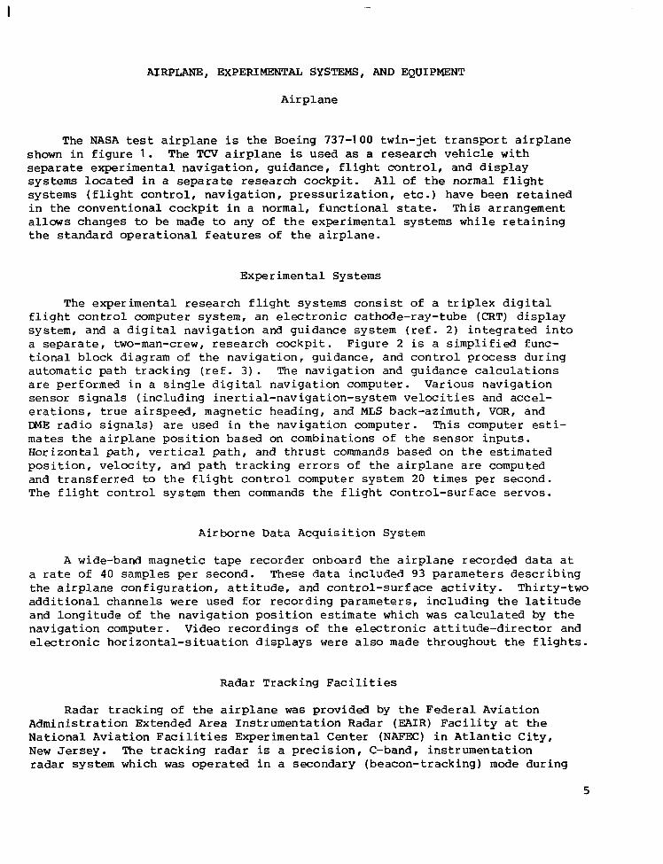
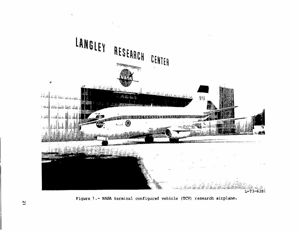
The NASA tes t a i r p l a n e is the Boeing 737-100 t w i n - j e t t r a n s p o r t a i r p l a n e shown i n f i g u r e 1 . The TCV a i r p l a n e is used as a r e s e a r c h v e h i c l e w i t h separate e x p e r i m e n t a l n a v i g a t i o n , g u i d a n c e , f l i g h t c o n t r o l , a n d d i s p l a y s y s t e m s l o c a t e d i n a separate r e s e a r c h cockpit. A l l o f t h e n o r m a l f l i g h t s y s t e m s ( f l i g h t c o n t r o l , n a v i g a t i o n , p r e s s u r i z a t i o n , etc.) have been re ta ined i n t h e c o n v e n t i o n a l cockpit i n a normal, f u n c t i o n a l state. This a r rangement allows changes to be made to any of t h e e x p e r i m e n t a l s y s t e m s w h i l e r e t a i n i n g t h e s t a n d a r d o p e r a t i o n a l f e a t u r e s o f t h e a i r p l a n e .
Experimental Systems
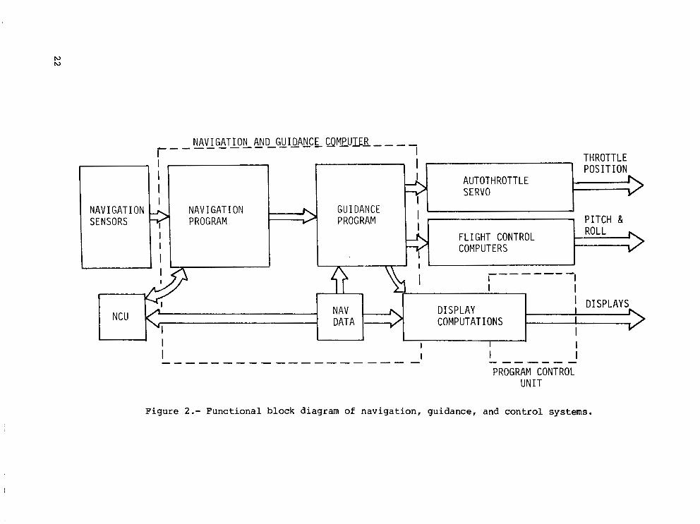
The e x p e r i m e n t a l r e s e a r c h f l i g h t s y s t e m s c o n s i s t o f a t r i p l e x d i g i t a l f l i g h t c o n t r o l computer sys t em, an e l ec t ron ic ca thode - ray - tube (CRT) d i s p l a y system, and a d i g i t a l n a v i g a t i o n and gu idance sys t em ( r e f . 2 ) i n t e g r a t e d i n t o a separate, two-man-crew, r e s e a r c h c o c k p i t . F i g u r e 2 is a s i m p l i f i e d f u n c - t i o n a l b l o c k d i a g r a m of t h e nav iga t ion , gu idance , and con t ro l p rocess du r ing automatic p a t h t r a c k i n g ( r e f . 3 ) . The nav iga t ion and gu idance ca l cu la t ions are per formed in a s i n g l e d i g i t a l n a v i g a t i o n computer. Var ious n a v i g a t i o n s e n s o r s i g n a l s ( i n c l u d i n g i n e r t i a l - n a v i g a t i o n - s y s t e m v e l o c i t i e s and accel- e r a t i o n s , t r u e a i r speed , magnet ic heading , and MLS back-azimuth, VOR, and DME r a d i o s i g n a l s ) are used i n t h e n a v i g a t i o n computer. Th i s computer es t i - m a t e s t h e a i r p l a n e p o s i t i o n b a s e d on combinat ions of t h e s e n s o r i n p u t s . H o r i z o n t a l p a t h , v e r t i c a l p a t h , and t h r u s t commands based on t h e e s t ima ted p o s i t i o n , v e l o c i t y , and p a t h t r a c k i n g e r r o r s of t h e a i r p l a n e a r e computed and t r a n s f e r r e d to t h e f l i g h t c o n t r o l computer system 20 times per second. The f l i g h t c o n t r o l s y s t e m t h e n comnands t h e f l i g h t c o n t r o l - s u r f a c e servos.
Airborne Data Acquis i t ion Sys tem
A wide-band magnetic tape recorder onboard t h e a i r p l a n e r e c o r d e d data a t a ra te of 40 samples per second. These d a t a i n c l u d e d 9 3 parameters d e s c r i b i n g t h e a i r p l a n e c o n f i g u r a t i o n , a t t i t u d e , a n d c o n t r o l - s u r f a c e a c t i v i t y . T h i r t y - t w o a d d i t i o n a l c h a n n e l s were used f o r r e c o r d i n g p a r a m e t e r s , i n c l u d i n g t h e l a t i t u d e and l ong i tude of t h e n a v i g a t i o n p o s i t i o n e s t i m a t e w h i c h was c a l c u l a t e d by t h e n a v i g a t i o n computer. V i d e o r e c o r d i n g s o f t h e e l e c t r o n i c a t t i t u d e - d i r e c t o r a n d e l e c t r o n i c h o r i z o n t a l - s i t u a t i o n d i s p l a y s were also made t h r o u g h o u t t h e f l i g h t s .
R a d a r T r a c k i n g F a c i l i t i e s
Radar t rack ing of t h e a i r p l a n e was provided by t h e F e d e r a l A v i a t i o n Adminis t ra t ion Extended Area Ins t rumenta t ion Radar (EAIR) F a c i l i t y a t t h e N a t i o n a l A v i a t i o n F a c i l i t i e s E x p e r i m e n t a l C e n t e r (NAFEC) i n A t l a n t i c C i t y , New J e r s e y . The t r a c k i n g r a d a r is a precision, C-band, i n s t r u m e n t a t i o n radar system which was operated i n a secondary (beacon- t racking) m o d e du r ing
5

t h e s e f l i g h t tests. S l a n t r a n g e , a z i m u t h a n g l e , a n d e l e v a t i o n a n g l e d a t a were recorded a t a 10-Hz sample rate on magnet ic tape. A l l a i r b o r n e a n d ground-based recorded data were time correlated for p o s t - f l i g h t p r o c e s s i n g a n d a n a l y s i s . P o s t - f l i g h t processing of the r ange , az imuth , and e l eva t ion d a t a c o n s i s t e d of convers ion to l a t i t u d e , l o n g i t u d e , a n d a l t i t u d e .
Radar accuracy, root mean s q u a r e (rms) , is stated (ref . 4) as 0.15 mrad, 5.6 m a t 37 040 m (20 n. m i . ) in az imuth and e leva t ion and 6 m i n r a n g e .
MLS and DME
The MLS u s e d d u r i n g t h e s e f l i g h t tests was a test bed sys t em o r i en ted fo r app roaches to runway 31 a t NAFEC. Th i s sys t em was a t ime-referenced scanning-beam system with a front-azimuth beam width o f lo , a l a t e r a l sweep a n g l e o f +60°, and nominal ver t ica l coverage up to 20°. The g l i d e s l o p e beam was l o wide and had an azimuthal coverage of approximately +60°. An MLS PDME w i t h o m n i d i r e c t i o n a l c o v e r a g e of approximate ly 37 040 m (20 n. m i . ) was used in conjunct ion wi th the f ront -az imuth s igna ls . The back-az imuth beam was 3O wide and had a l a t e ra l sweep a n g l e o f +40°. Vertical coverage was between l o and 20°.
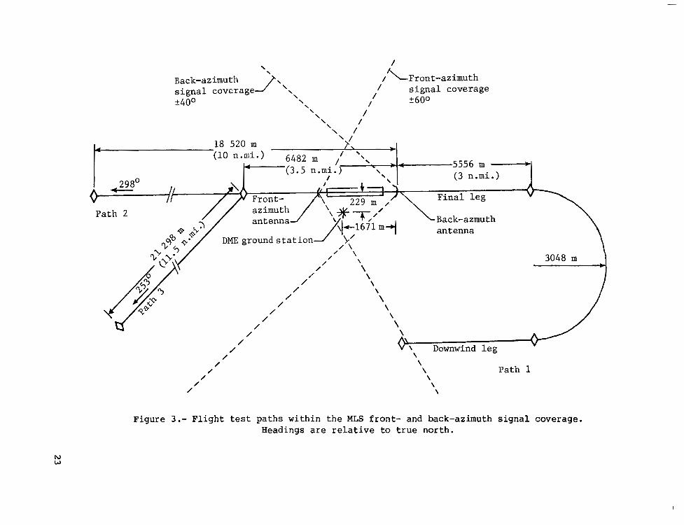
The A t l a n t i c C i t y DME, normally u s e d f o r e n r o u t e n a v i g a t i o n , was used d u r i n g t h e b a c k - a z i m u t h f l i g h t t e s t i n g . T h i s DME is located a t t h e a i r p o r t 1671 m pas t the back-az imuth an tenna and 229 m l e f t of t h e runway c e n t e r l i n e ( f i g . 3 ) .
When the nav iga t ion sys t em upda ted its p o s i t i o n estimate w i t h d u a l DME, t h e A t l a n t i c C i t y DME was a l w a y s u s e d i n c o n j u n c t i o n w i t h o t h e r DME i n t h e a r e a . T h e n a v i g a t i o n s y s t e m a u t o m a t i c a l l y s e l e c t e d , t u n e d , a n d c h e c k e d t h e v a l i d i t y of t h e o t h e r DME o n t h e b a s i s o f s t r e n g t h o f s i g n a l and s t a t i o n l o c a t i o n g e o m e t r i c c h a r a c t e r istics so t h a t good pos i t i on estimates r e s u l t e d . T h e s e g e o m e t r i c c h a r a c t e r i s t i c s are d e s c r i b e d i n r e f e r e n c e 2.
Swi tch ing Logic o f Ai rborne MLS Receiver Antenna
The TCV a i r p l a n e was equipped with two MLS r e c e i v e r a n t e n n a s to e n s u r e t h a t t h e g r e a t e s t p o s s i b l e s i g n a l s t r e n g t h was d e l i v e r e d to t h e MLS r e c e i v e r r e g a r d l e s s of t h e a i r p l a n e d i r e c t i o n of f l i g h t , its a t t i t u d e , or its p o s i t i o n w i t h i n t h e MLS s igna l coverage . The forward antenna was l o c a t e d o n top o f t h e f u s e l a g e j u s t a b o v e t h e f o r w a r d cockpit. The rear antenna was mounted on t h e b o t t o m o f t h e f u s e l a g e b e l o w t h e a i r p l a n e t a i l . The MLS a i r b o r n e r e c e i v e r c o n t a i n e d t h e logic to determine which antenna was p r o v i d i n g t h e g r e a t e s t s i g n a l s t r e n g t h . The r ece ive r s en t a p a i r of d i s c r e t e l o g i c s i g n a l s to an ex te rna l an t enna swi t ch to select t h e a p p r o p r i a t e a n t e n n a .
A d d i t i o n a l h a r d w a r e l o g i c i n t h e f l i g h t c o n t r o l computers f o r c e d s e l e c t i o n o f t h e f o r w a r d a n t e n n a w h i l e o p e r a t i n g i n t h e MLS f r o n t - c o u r s e s i g n a l c o v e r a g e , r e g a r d l e s s of t h e r e l a t i v e s i g n a l s t r e n g t h s a t t h e f o r w a r d a n d a f t a n t e n n a s . T h i s a d d i t i o n a l a n t e n n a - s e l e c t i o n logic was r e q u i r e d b e c a u s e t h e f l i g h t c o n t r o l computers d id no t have t he necessa ry so f tware fo r an t enna swi t ch ing .
6
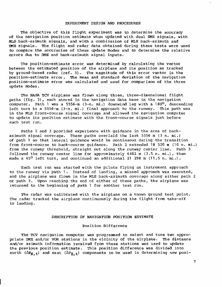
EXPERIMENT DESIGN AND PROCEDURES
The o b j e c t i v e of t h i s f l i g h t e x p e r i m e n t was to de te rmine t he accu racy of t h e n a v i g a t i o n p o s i t i o n estimate when upda ted w i th dua l IXlE s i g n a l s , w i t h MLS back-az imuth s igna l s , and w i th a combinat ion of MLS back-azimuth and DME s i g n a l s . The f l i g h t and radar d a t a o b t a i n e d d u r i n g t h e s e tests were used to compare t h e a c c u r a c i e s o f t h e s e u p d a t e modes and to d e t e r m i n e t h e re la t ive errors due to DME and back-az imuth s igna l inputs .
The pos i t i on -es t ima te error was determined by c a l c u l a t i n g t h e v e c t o r between t h e e s t i m a t e d p o s i t i o n of t h e a i r p l a n e a n d its p o s i t i o n as t r a c k e d by ground-based radar ( ref . 5 ) . The magnitude of t h i s error v e c t o r is t h e p o s i t i o n - e s t i m a t e error. The mean a n d s t a n d a r d d e v i a t i o n o f t h e n a v i g a t i o n p o s i t i o n - e s t i m a t e error was ca l cu la t ed and u sed for comparison of t h e t h r e e update modes.
The NASA TCV a i r p l a n e was flown a l o n g t h r e e , t h r e e - d i m e n s i o n a l f l i g h t p a t h s ( f i g . 3 ) , e a c h s t o r e d i n t h e ' n a v i g a t i o n data base i n t h e n a v i g a t i o n computer. Path 1 was a 5556-m (3-n. m i . ) downwind l e g w i t h a 1 80°, descending l e f t t u r n to a 5556-m (3-n. m i . ) f i n a l a p p r o a c h to t h e runway. This path was i n t h e MLS f ron t - cour se s igna l cove rage and allowed t h e navigat ion computer to update its p o s i t i o n e s t i m a t e w i t h t h e f r o n t - c o u r s e s i g n a l s j u s t b e f o r e each test run.
Pa ths 2 and 3 provided exper ience wi th gu idance in t h e area of back- a z i m u t h s i g n a l c o v e r a g e . T h e s e p a t h s o v e r l a i d t h e l a s t 5556 m ( 3 n. m i . ) of p a t h 1 so t h a t l a t e r a l g u i d a n c e w o u l d be c o n t i n u o u s d u r i n g t h e t r a n s i t i o n from f ront -course to back-cour se guidance. P a t h 2 extended 18 520 m (1 0 n. m i .) from t h e runway t h r e s h o l d , s t r a i g h t o u t a l o n g t h e r u n w a y c e n t e r l i n e . P a t h 3 f o l l o w e d t h e runway c e n t e r l i n e for approximately 6482 m (3 .5 n . m i . ) , t h e n made a 45O l e f t t u r n , a n d c o n t i n u e d a n a d d i t i o n a l 21 298 m (11.5 n. m i . ) .
Each tes t run was s ta r ted w i t h t h e p i l o t s f l y i n g a n i n s t r u m e n t a p p r o a c h to t h e runway v i a p a t h 1 . I n s t e a d o f l a n d i n g , a missed approach was executed, and t h e a i r p l a n e was flown i n t h e MLS back-azimuth coverage a long either p a t h 2 or pa th 3 . Upon r e a c h i n g t h e e n d o f e i t h e r of t h e s e p a t h s , t h e a i r p l a n e was r e t u r n e d to t h e b e g i n n i n g o f path 1 f o r a n o t h e r test run.
The radar was c a l i b r a t e d w i t h t h e a i r p l a n e o n a known ground test p o i n t . The radar tracked t h e a i r p l a n e c o n t i n u o u s l y d u r i n g t h e f l i g h t from take-off to l a n d i n g .
DESCRIPTION OF NAVIGATION POSITION ESTIMATE
P o s i t i o n D i f f e r e n c e
The TCV navigat ion computer was p r o g r a m e d to select and t une two appro- pr ia te DME and/or VOR s t a t i o n s i n t h e v i c i n i t y of t h e a i r p l a n e . The d i s t a n c e and/or az imuth in format ion rece ived from t h e s e s t a t i o n s was used to update t h e p r e v i o u s p o s i t i o n estimate. T h i s p o s i t i o n d i f f e r e n c e was d i v i d e d i n t o n o r t h (APN,t) and east (APE,t) components to be used i n de t e rmin ing new posi-
7
t i o n a n d v e l o c i t y estimates. The dual DME update mode, t h e p r i m a r y p o s i t i o n - e s t i m a t e d i f f e r e n c e m o d e , was d i s p l a y e d as IDD on t h e e l e c t r o n i c map d i s p l a y s for e a c h o f t h e f l i g h t crews.
Othe r sou rces o f nav iga t ion i n fo rma t ion cou ld also be used to de te rmine p o s i t i o n d i f f e r e n c e s . W h i l e o p e r a t i n g i n t h e MLS back-azimuth s ignal cover- age, these pos i t ion-update components were ca lcu la ted wi th back-az imuth and DME in fo rma t ion . Th i s upda te mode was shown o n t h e pilots ' e l e c t r o n i c map d i s p l a y as IBD ( i n e r t i a l v e l o c i t y , b a c k a z i m u t h , DEIIE). I f no DME was a v a i l a b l e , t h e estimate mode was IBX ( i n e r t i a l v e l o c i t y , b a c k a z i m u t h a l o n e ) . I n s u b s e q u e n t s e c t i o n s , t h e e q u a t i o n s used i n t h e I B D and IBX upda te modes are p resen ted . The e q u a t i o n s u s e d i n t h e I D D update mode are p r e s e n t e d i n r e f e r e n c e 2.
I n t h e TCV n a v i g a t i o n s y s t e m t h e same p o s i t i o n - e s t i m a t e c a l c u l a t i o n s , described i n t h e n e x t s e c t i o n , were used r e g a r d l e s s o f t h e p o s i t i o n - u p d a t e mode used to de te rmine t he no r th and east components.
P o s i t i o n Estimate
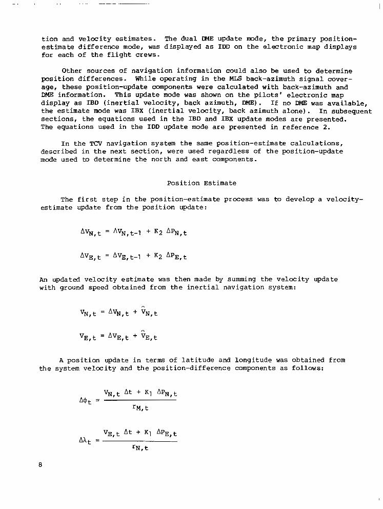
The f i r s t step i n t h e p o s i t i o n - e s t i m a t e process was to develop a v e l o c i t y - estimate update f rom the pos i t ion update :
An u p d a t e d v e l o c i t y e s t i m a t e was then made by summing t h e v e l o c i t y update with ground speed o b t a i n e d f r o m t h e i n e r t i a l n a v i g a t i o n s y s t e m :
V N , t = A v N , t " v N , t
A p o s i t i o n u p d a t e i n terms o f l a t i t u d e and l o n g i t u d e was obta ined f rom t h e s y s t e m v e l o c i t y a n d t h e p o s i t i o n - d i f f e r e n c e c o m p o n e n t s as fo l lows :
V N , t At " K1 A P N , t
rM, t A O t =
8
I
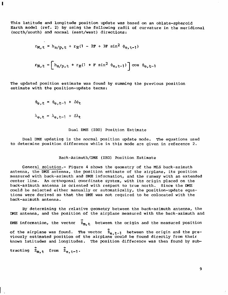
T h i s l a t i t u d e a n d l o n g i t u d e p o s i t i o n u p d a t e was based on an ob la t e - sphe ro id E a r t h model (ref. 2) by u s i n g t h e f o l l o w i n g radi i of c u r v a t u r e i n t h e m e r i d i o n a l (north/south) and normal (east/west) d i r e c t i o n s :
The upda ted pos i t i on estimate was found by summing t h e p r e v i o u s p o s i t i o n estimate w i t h t h e p o s i t i o n - u p d a t e terms:
Dual DME ( I D D ) P o s i t i o n E s t i m a t e
Dual DME updat ing is t h e n o r m a l p o s i t i o n u p d a t e mode. The equa t ions u sed to d e t e r m i n e p o s i t i o n d i f f e r e n c e w h i l e i n t h i s mode are g i v e n i n r e f e r e n c e 2 .
Back-Azimuth/DME ( IBD) P o s i t i o n Estimate
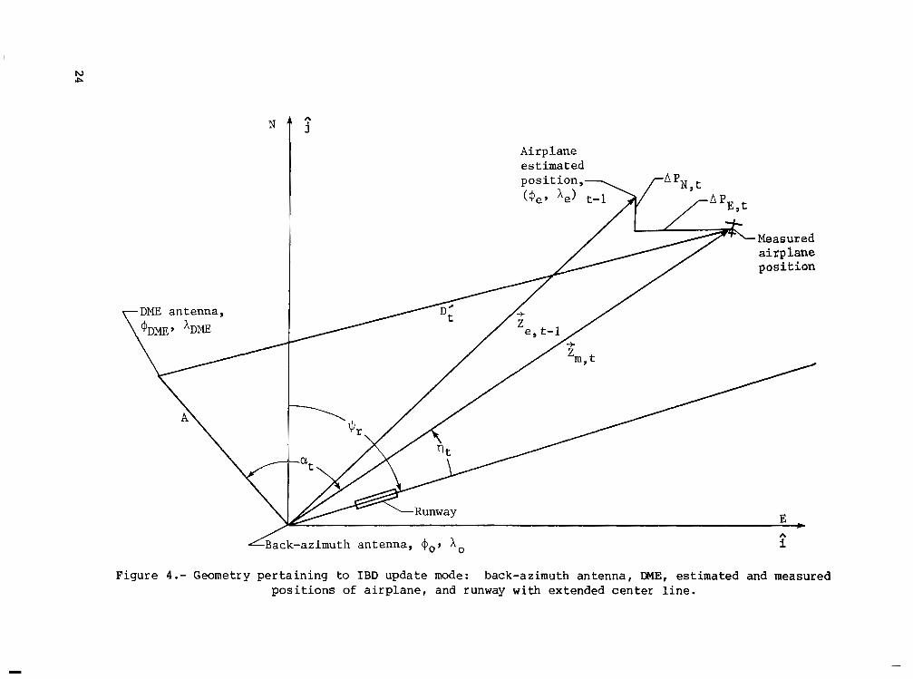
G e n e r a l s o l u t i o n . - F i g u r e 4 shows the geometry of t h e MLS back-azimuth a n t e n n a , t h e DME a n t e n n a , t h e p o s i t i o n estimate o f t h e a i r p l a n e , i ts p o s i t i o n measured with back-azimuth and DME information, and the runway with an extended c e n t e r l i n e . An o r thogona l coo rd ina te sys t em, w i t h i t s o r i g i n p l a c e d o n t h e back-azimuth antenna is o r i e n t e d w i t h respect to t r u e n o r t h . S i n c e t h e DME c o u l d b e s e l e c t e d e i t h e r m a n u a l l y or a u t o m a t i c a l l y , t h e p o s i t i o n - u p d a t e e q u a - t i o n s were d e r i v e d so t h a t t h e DME was n o t r e q u i r e d to be colocated w i t h t h e back-azimuth antenna.
By de termining the re la t ive geometry be tween the back-az imuth an tenna , the DME a n t e n n a , a n d t h e p o s i t i o n o f t h e a i r p l a n e m e a s u r e d w i t h the back-azimuth and
9
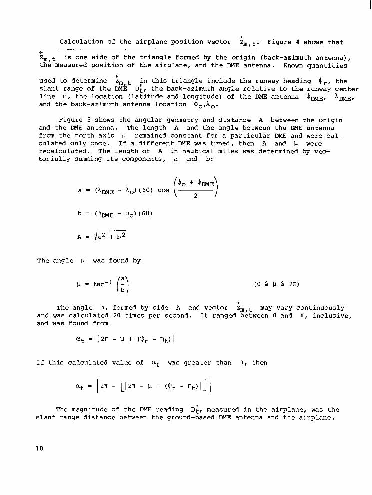
C a l c u l a t i o n of t h e a i r p l a n e p o s i t i o n vector h,t.- F i g u r e 4 shows t h a t +
+ Z,,t is o n e s i d e of t h e t r i a n g l e f o r m e d by t h e o r i g i n ( b a c k - a z i m u t h a n t e n n a ) , t he measu red pos i t i on of t h e a i r p l a n e , a n d t h e DME antenna . Known q u a n t i t i e s
used to de termine Z m , t i n t h i s t r i a n g l e i n c l u d e t h e runway heading $r , t h e s l a n t r a n g e of t h e DME D;, t h e b a c k - a z i m u t h a n g l e r e l a t i v e to t h e runway center l i n e rl, t h e l o c a t i o n ( l a t i t u d e a n d l o n g i t u d e ) of t h e DME antenna @DME, x,,, and the back-az imuth an tenna loca t ion $o,xo.
+
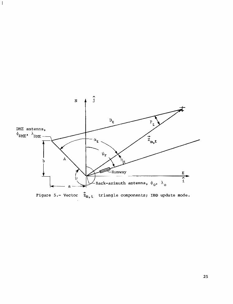
F i g u r e 5 shows the angu la r geomet ry and d i s t ance A b e t w e e n t h e o r i g i n and t h e DME antenna . The l e n g t h A and t h e a n g l e b e t w e e n t h e DME antenna f r o m t h e n o r t h a x i s p r ema ined cons t an t fo r a p a r t i c u l a r DME and were cal- culated on ly once . If a d i f f e r e n t DME was tuned , t hen A and 1-1 were r e c a l c u l a t e d . T h e l e n g t h o f A i n n a u t i c a l miles was determined by vec- t o r i a l l y summing i ts components, a and b:
a = (ADME - x,) (60) COS t o +zmDME)
The ang le 1-1 was found by
The ang le a , formed by s i d e A and vector h,t may v a r y c o n t i n u o u s l y +
and was c a l c u l a t e d 20 times per second. I t ranged between 0 and IT, i n c l u s i v e , and was found from
I f t h i s c a l c u l a t e d v a l u e of a t was g r e a t e r t h a n IT, t h e n
The magni tude o f the DME reading DL, measured i n t h e a i r p l a n e , was t h e s l an t r ange d i s t ance be tween t he g round-based DME a n t e n n a a n d t h e a i r p l a n e .
10

T h i s d i s t a n c e was s l an t - r ange -co r rec t ed to de te rmine t he g round d i s t ance D t be tween the a i rp lane and DME
D t = D; s i n [..s-’ ( - -D, )I ha/p, t - ~ D M E
Angle P, formed by t h e v e c t o r Z m , t a n d s i d e D t , cou ld va ry con t inuous ly +
and was calculated 20 times per second. From t h e r e l a t i o n ,
a n g l e P t was determined from
Comparison of t h e square o f s i d e A w i t h t h e sum of t he squa re of side D t and t he squa re of t h e magni tude o f the vec tor Z e , t - l (estimated a i r p l a n e p o s i t i o n v e c t o r ) d e t e r m i n e d whether a n g l e P t was obtuse or acute. Hence,
P t = (
T h e m a g n i t u d e o f t h e e s t i m a t e d a i r p l a n e p o s i t i o n v e c t o r Ze,t-l was used as an
approx ima t ion fo r Z m , t . The magnitude of Z e l t - l was + +
11
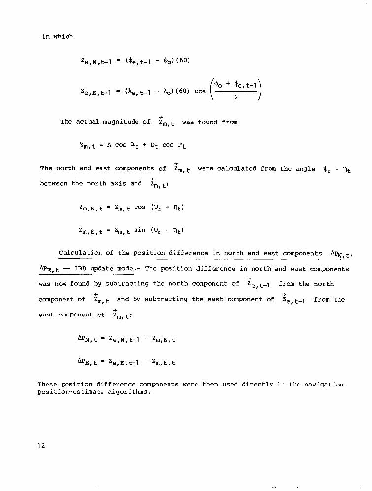
in which
The actual magnitude of Zm, t was found from -+
The north and east components of Zmlt were calculated from the angle 9, - qt between the north axis and Zm,t:
+
+
Zm,N,t = %I, t cos (9, - qt)
Calculation of' the position difference in north and east components A P ~ , ~ , -~ - - - -~ " .
&E,t - IBD update mode.- The position difference in north and east components was now found by subtracting the north component of Ze,t-l from the north
component of Zmlt and by subtracting the east component oE Zelt-1 from the
east component of Zm, t:
-+
-F -+
-+
These position difference components were then used directly in the navigation position-estimate algorithms.
12
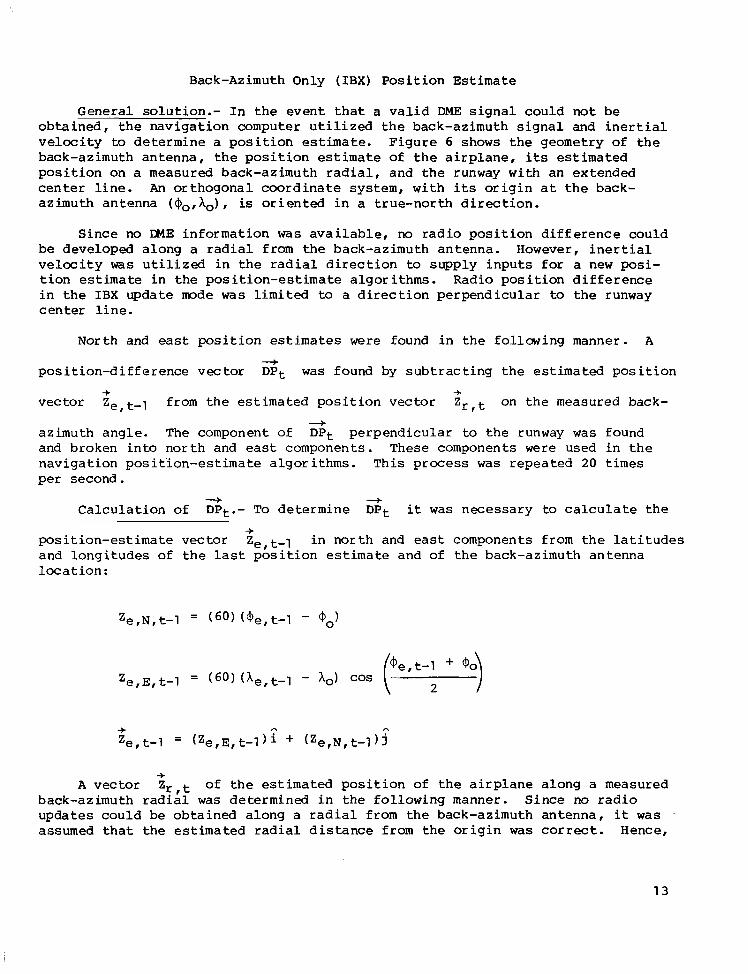
Back-Azimuth Only ( IBX) P o s i t i o n E s t i m a t e
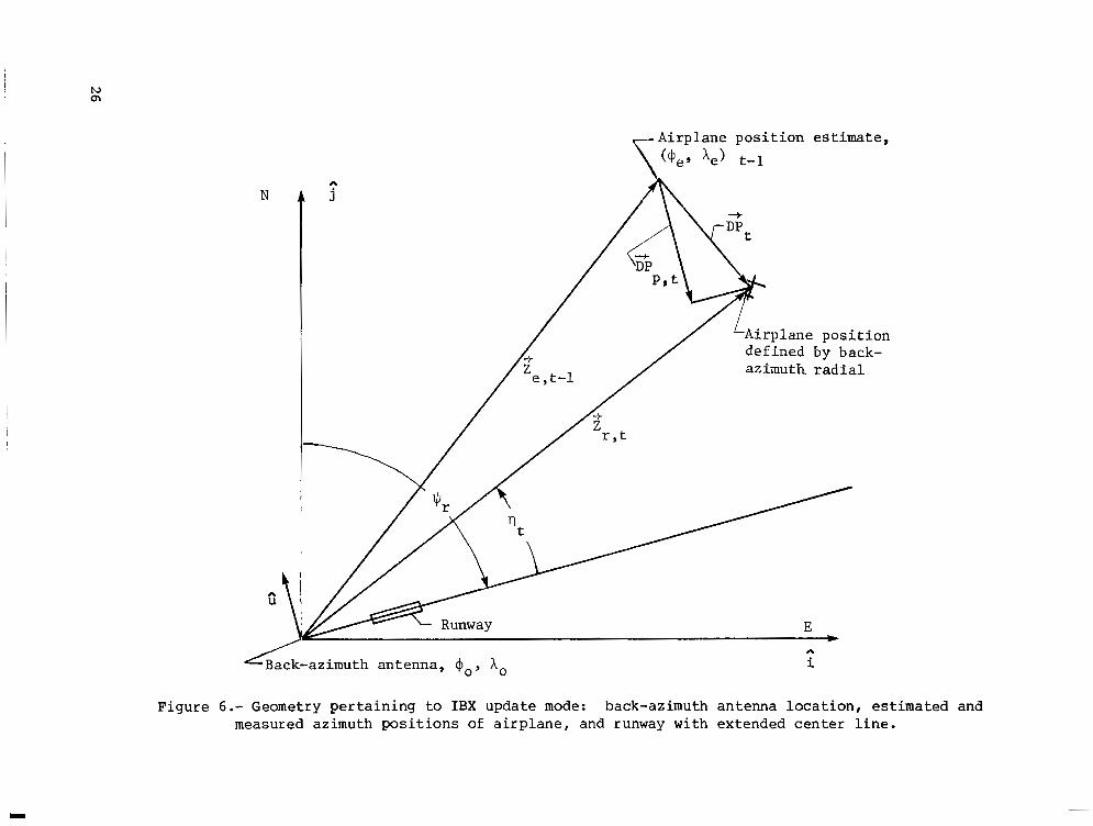
G e n e r a l s o l u t i o n . - I n t h e e v e n t t h a t a v a l i d DME s i g n a l c o u l d n o t be o b t a i n e d , t h e n a v i g a t i o n c o m p u t e r u t i l i z e d t h e b a c k - a z i m u t h s i g n a l a n d i n e r t i a l v e l o c i t y to d e t e r m i n e a position estimate. F i g u r e 6 shows the geometry of t h e back-az imuth an tenna , t he pos i t i on estimate of t h e a i r p l a n e , i ts e s t i m a t e d p o s i t i o n o n a measured back-azimuth radial , and the runway with an extended center l i n e . An or thogona l coo rd ina te sys t em, w i th its o r i g i n a t t h e back- azimuth antenna (($o,Ao), is o r i e n t e d i n a t r u e - n o r t h d i r e c t i o n .
S ince no IME i n f o r m a t i o n was a v a i l a b l e , no radio p o s i t i o n d i f f e r e n c e c o u l d be developed a long a radial from the back-azimuth antenna. However, i n e r t i a l v e l o c i t y was u t i l i z e d i n t h e r a d i a l d i r e c t i o n to s u p p l y i n p u t s for a new posi- t i o n estimate i n t h e p o s i t i o n - e s t i m a t e a l g o r i t h m s . R a d i o p o s i t i o n d i f f e r e n c e i n t h e IBX update mode was limited to a d i r e c t i o n p e r p e n d i c u l a r to t h e runway c e n t e r l i n e .
North and east p o s i t i o n estimates were found i n t h e f o l l o w i n g m a n n e r . A
p o s i t i o n - d i f f e r e n c e v e c t o r DPt was found by s u b t r a c t i n g t h e estimated p o s i t i o n
v e c t o r Ze, t-l from t h e e s t i m a t e d p o s i t i o n v e c t o r Z r , on t h e measured back-
az imuth angle . The component of DPt p e r p e n d i c u l a r to t h e runway was found and broken into north and east components. These components were used i n t h e naviga t ion pos i t5 .on-es t imate a lgor i thms. This p rocess was r e p e a t e d 20 times per second.
"+
+ +
"t
C a l c u l a t i o n of D P t . - To d e t e r m i n e D P t it was necessary to c a l c u l a t e t h e "-t "-t
+ pos i t i on -es t ima te vec to r Ze , tT1 i n no r th and east componen t s f rom the l a t i t udes a n d l o n g i t u d e s o f t h e l as t p o s i t i o n estimate and of t h e back-azimuth antenna
+ A v e c t o r Z r , o f t h e e s t i m a t e d p o s i t i o n o f t h e a i r p l a n e a l o n g a measured
back-azimuth radial was d e t e r m i n e d i n t h e f o l l o w i n g m a n n e r . S i n c e n o radio upda te s cou ld be ob ta ined a long a r a d i a l from the back-azimuth antenna, it was assumed t h a t t h e estimated radial d i s t a n c e f r o m t h e o r i g i n was correct. Hence,
13
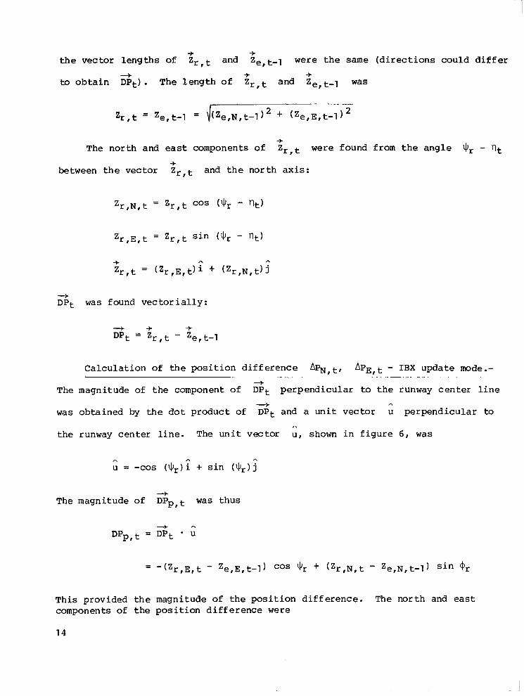
t h e v e c t o r l e n g t h s o f Zr , t and ZeIt-l were t h e same ( d i r e c t i o n s c o u l d d i f f e r
to o b t a i n DPt) . The l eng th o f Zr, t and Ze, t-1 was
-+ -+
+ .+ -+
-f The north and east components Of z r , t were found f rom the angle 'IJr - rlt
-+ between t h e v e c t o r Zr, t and t h e n o r t h a x i s :
3 DPt was f o u n d v e c t o r i a l l y :
C a l c u l a t i o n o f t h e p o s i t i o n d i f f e r e n c e &,t, APE,^ - IBX update mode.- ....... . . ". - .. .. . .
The magnitude of the component of D P t p e r p e n d i c u l a r to t h e r u n w a y c e n t e r l i n e
was obta ined by t h e dot product of D P t and a u n i t v e c t o r u p e r p e n d i c u l a r t o
t h e runway c e n t e r l i n e . The u n i t v e c t o r u I shown i n f i g u r e 6 , was
3
"-+ A
A
The magnitude of
DPp,t =
This p rov ided t he components of the
"f DPp, t was t h u s
DPt * U 3 A
m a g n i t u d e o f t h e p o s i t i o n d i f f e r e n c e . The no r th and east p o s i t i o n d i f f e r e n c e were
14
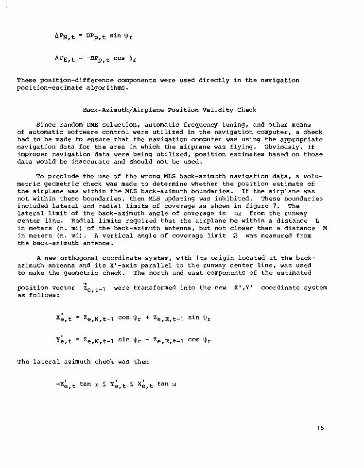
These pos i t ion-d i f fe rence components were u s e d d i r e c t l y i n t h e n a v i g a t i o n p o s i t i o n - e s t i m a t e a l g o r i t h m s .
Back-Azimuth/Airplane Posi t ion Val idi ty Check
S i n c e random DME s e l e c t i o n , a u t o m a t i c f r e q u e n c y t u n i n g , a n d o t h e r means o f au tomat i c so f tware control were u t i l i z e d i n t h e n a v i g a t i o n c o m p u t e r , a check had to b e made to e n s u r e t h a t t h e n a v i g a t i o n c o m p u t e r was u s i n g t h e a p p r o p r i a t e n a v i g a t i o n data for t h e area i n w h i c h t h e a i r p l a n e was f ly ing . Obv ious ly , if improper naviga t ion da ta were b e i n g u t i l i z e d , p o s i t i o n estimates based on t hose data would be inaccura t e and shou ld no t be u sed .
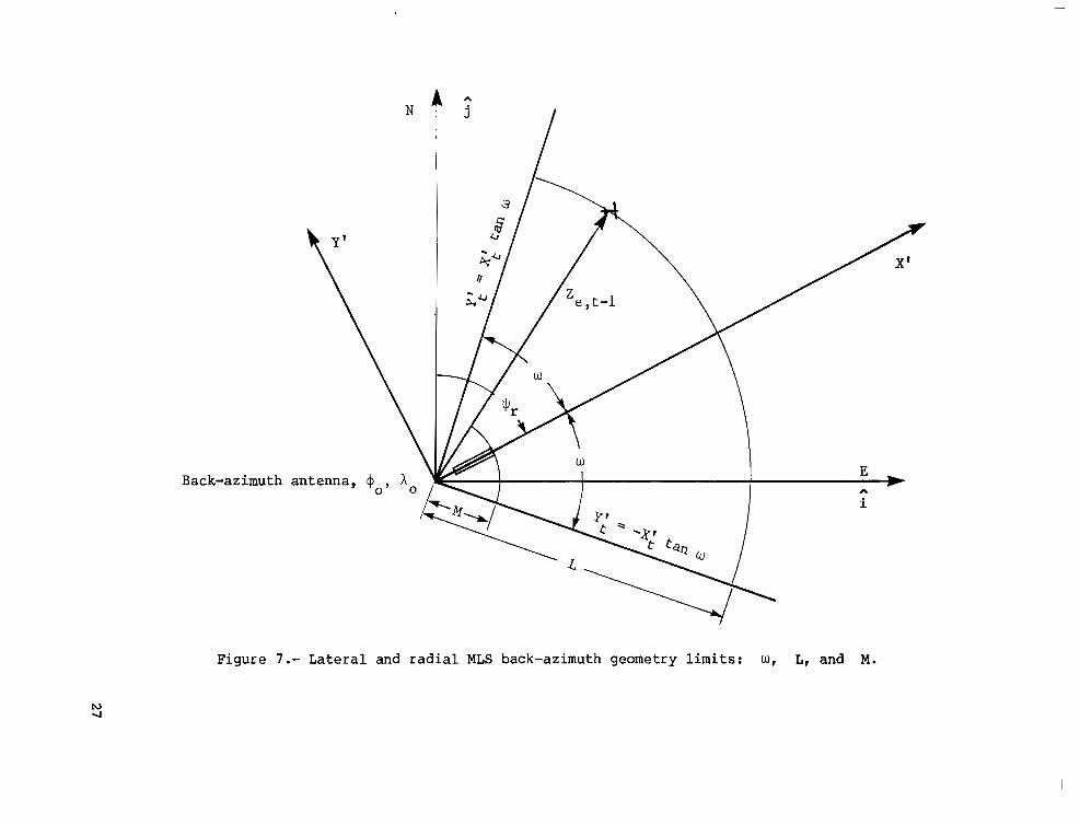
To p r e c l u d e t h e u s e of t h e wrong MLS back-azimuth navigat ion data, a volu- metric geometric check was made to determine whether t h e p o s i t i o n estimate of t h e a i r p l a n e was w i t h i n t h e MLS back-azimuth boundaries. If t h e a i r p l a n e was n o t w i t h i n these boundar i e s , t hen MLS updat ing was i n h i b i t e d . These boundar ies i n c l u d e d l a t e r a l a n d r a d i a l limits of coverage as shown i n f i g u r e 7. The l a t e r a l limit of t h e back-azimuth angle of coverage is Lu from t h e runway center l i n e . R a d i a l limits r e q u i r e d t h a t t h e a i r p l a n e b e w i t h i n a d i s t a n c e L i n meters (n . m i ) o f the back-az imuth an tenna , bu t no t closer t h a n a d i s t a n c e M i n meters (n. m i ) . A v e r t i c a l a n g l e of coverage limit Q was measured from the back-azimuth antenna.
A new o r thogona l coo rd ina te sys t em, w i th its o r i g i n l o c a t e d a t t h e back- azimuth antenna and its X I - a x i s p a r a l l e l to t h e runway c e n t e r l i n e , was used to make the geometr ic check. The north and east components of the estimated
p o s i t i o n v e c t o r Z e l t - l were t r a n s f o r m e d i n t o t h e new X ' , Y ' coo rd ina te sys t em as f o l l o w s :
-f
The l a t e r a l azimuth check was then
1 5
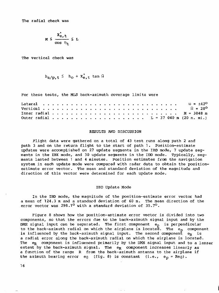
The radial check was
T h e v e r t i c a l c h e c k was
ha/p, t 5 ho + X;, t t a n 52
Fo r t hese tests, t h e MLS back-azimuth coverage limits were
Lateral . . . . . . . . . . . . . . . . . . . . . . . . . . . . . U = +420 Vertical . . . . . . . . . . . . . . . . . . . . . . . . . . . . . 52 = 200 I n n e r r a d i a l . . . . . . . . . . . . . . . . . . . . . . . . . . . M = 3048 m Outer radial . . . . . . . . . . . . . . . . . . . . L = 37 040 m (20 n. m i .)
RESULTS AND DISCUSSION
F l i g h t d a t a were ga the red on a t o t a l of 43 test r u n s a l o n g p a t h 2 and p a t h 3 a n d o n t h e r e t u r n f l i g h t to t h e s t a r t of p a t h 1 . P o s i t i o n - e s t i m a t e updates were accomplished on 27 u p d a t e s e g m e n t s i n t h e IBD mode, 7 update seg- m e n t s i n t h e IBX mode, and 30 update s e g m e n t s i n t h e IDD mode. T y p i c a l l y , s e g - ments lasted between 1 and 4 m i n u t e s . P o s i t i o n estimates f r o m t h e n a v i g a t i o n sys t em in each upda te mode were compared with radar data to o b t a i n t h e p o s i t i o n - estimate error vec tor . The mean a n d s t a n d a r d d e v i a t i o n of the magni tude and d i r e c t i o n of t h i s v e c t o r were de te rmined fo r each upda te mode.
IBD Update Mode
I n t h e IBD mode, t he magn i tude of t h e p o s i t i o n - e s t i m a t e error vector had a mean of 124.3 m and a s t a n d a r d d e v i a t i o n of 60 m. The mean d i r e c t i o n o f t h e error v e c t o r was 298.1° w i t h a s t a n d a r d d e v i a t i o n o f 35.7O.
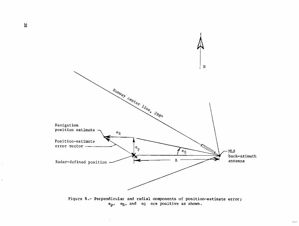
F i g u r e 8 shows how t h e p o s i t i o n - e s t i m a t e error v e c t o r is d i v i d e d i n t o t w o components, so t h a t t h e errors due to the back -az imuth s igna l i npu t and by t he DME s i g n a l i n p u t c a n be separated. The f i r s t component ep is p e r p e n d i c u l a r to the back-az imuth rad ia l on which the a i rp lane is l o c a t e d . The ep component i s i n f l u e n c e d by the back -az imuth s igna l i npu t . The second component 41 is a r a d i a l error a l o n g t h e b a c k - a z i m u t h r a d i a l o n w h i c h t h e a i r p l a n e is l o c a t e d . The eR component is i n f l u e n c e d p r i m a r i l y b y t h e DME s i g n a l i n p u t a n d t o a lesser e x t e n t by the back-az imuth s igna l . The e R componen t i nc reases l i nea r ly as a f u n c t i o n of the r ange R from the back-azimuth antenna to t h e a i r p l a n e i f t he az imuth bea r ing error ee ( f i g . 8) is c o n s t a n t (i.e., ep = R e o ) .
16
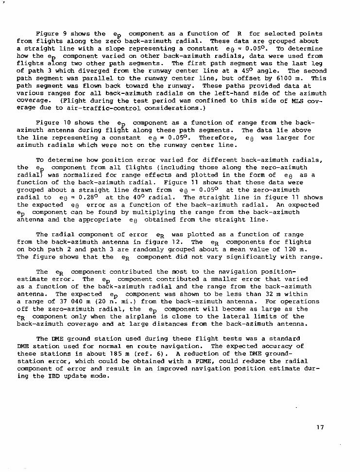
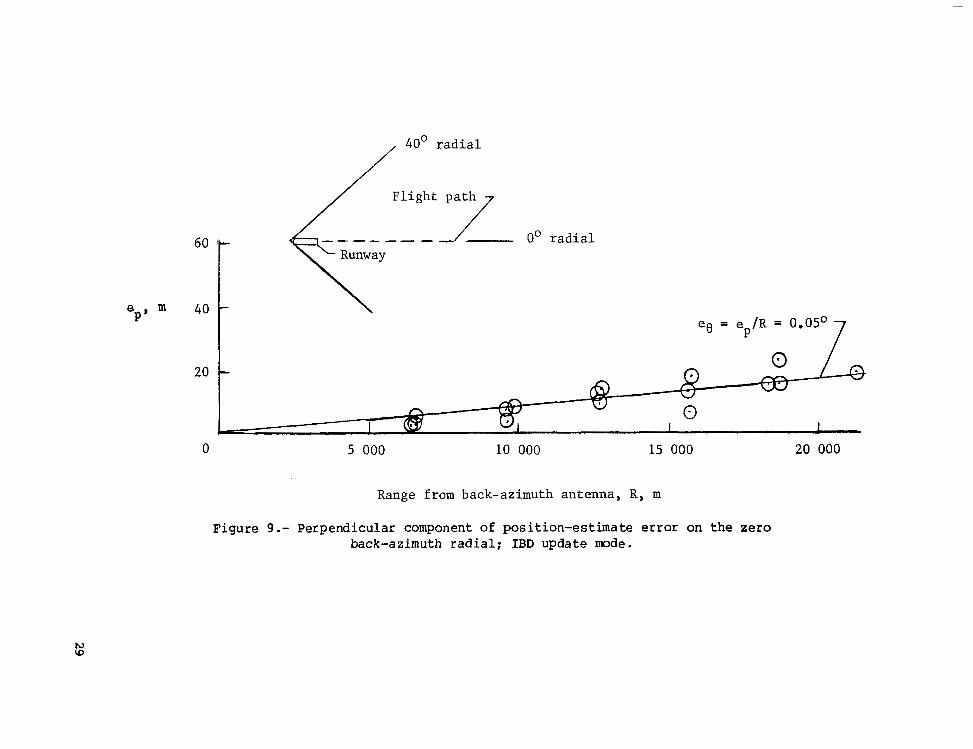
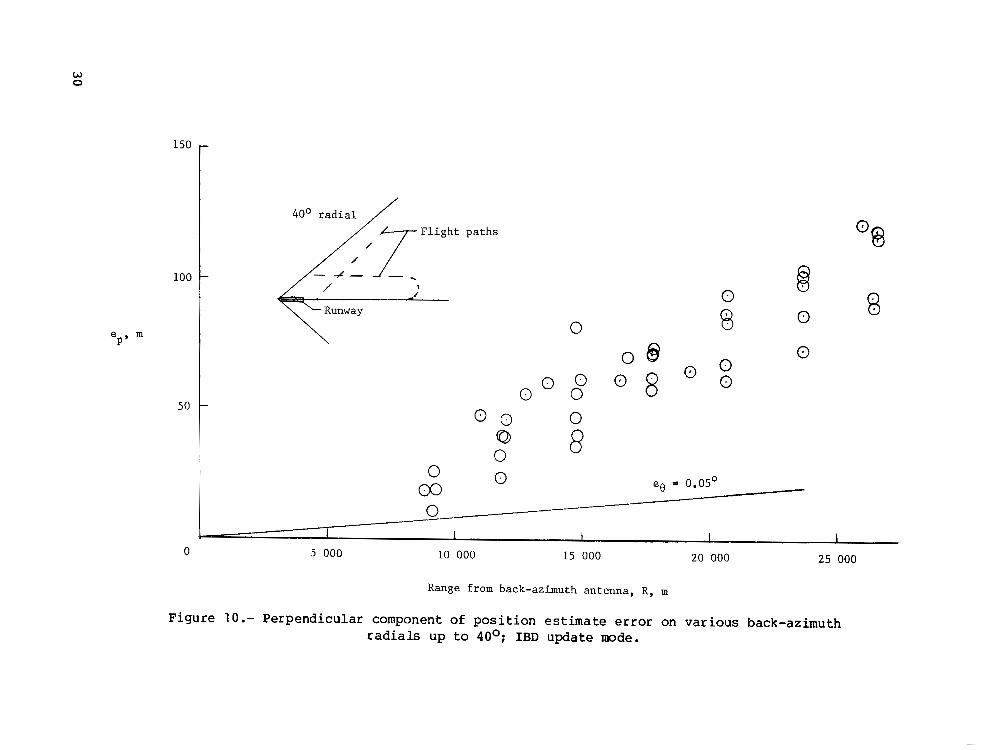
F i g u r e 9 shows t h e ep component as a f u n c t i o n of R for s e l e c t e d p o i n t s f r o m f l i g h t s a l o n g t h e z e r o b a c k - a z i m u t h r a d i a l . T h e s e data are grouped about a s t r a i g h t l i n e w i t h a slope r e p r e s e n t i n g a c o n s t a n t ee = 0.05O. To de termine how t h e e component var ied on o ther back-az imuth rad ia l s , data were used from f l i g h t s ayong t w o o the r pa th s egmen t s . The f irst path segment was t h e last l e g of p a t h 3 which diverged from t h e runway c e n t e r l i n e a t a 45O angle . The second path segment was paral le l to t h e runway c e n t e r l i n e , b u t o f f s e t by 6100 m. This path segment was flown back toward the runway. These pa ths p rovided da ta a t v a r i o u s r a n g e s for a l l back-azimuth radials on t h e l e f t - h a n d s i d e of the az imuth coverage. ( F l i g h t d u r i n g t h e test p e r i o d was c o n f i n e d to t h i s s i d e of MLS cov- e rage due to a i r - t r a f f i c - c o n t r o l c o n s i d e r a t i o n s . )
F i g u r e 10 shows t h e e component as a f u n c t i o n o f r a n g e from t h e back- a z i m u t h a n t e n n a d u r i n g f l i g f t a l o n g t h e s e p a t h s e g m e n t s . The data l i e above t h e l i n e r e p r e s e n t i n g a c o n s t a n t e e = 0.05O. T h e r e f o r e , ee was l a r g e r for az imuth rad ia l s which were n o t o n t h e runway c e n t e r l i n e .
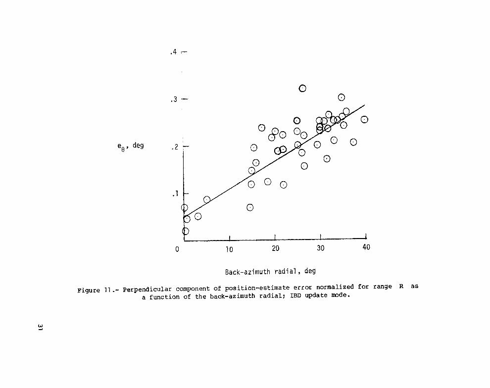
To de termine how p o s i t i o n error v a r i e d f o r d i f f e r e n t b a c k - a z i m u t h radials, t h e ep component from a l l f l i g h t s ( i n c l u d i n g those a long the zero-az imuth r a d i a l ) was n o r m a l i z e d f o r r a n g e e f f e c t s a n d p l o t t e d i n t h e f o r m o f ee as a f u n c t i o n of the back -az imuth r ad ia l . F igu re 11 shows t h a t t h e s e d a t a were grouped about a s t r a i g h t l i n e drawn from ee = 0.05O a t t h e z e r o - a z i m u t h rad ia l t o ee = 0.28O a t t h e 40° r a d i a l . The s t r a i g h t l i n e i n f i g u r e 11 shows t h e e x p e c t e d ee error as a f u n c t i o n of t h e back-az imuth rad ia l . An expec ted ep component can be found by mu l t ip ly ing t he r ange from the back-azimuth an tenna and t he appropriate ee o b t a i n e d from t h e s t r a i g h t l i n e .
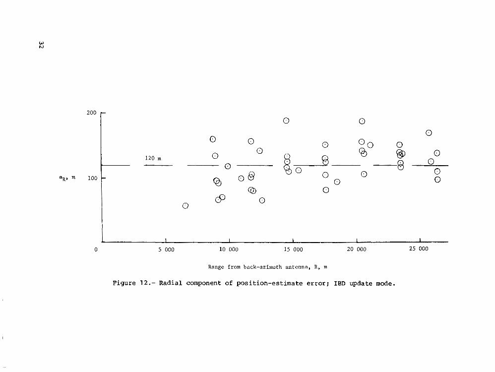
The rad ia l component of error eR was plotted as a f u n c t i o n of range f rom the back -az imuth an tenna i n f i gu re 12 . The e R c o m p o n e n t s f o r f l i g h t s on bo th pa th 2 and pa th 3 are randomly grouped about a mean va lue o f 120 m. The f igure shows t h a t t h e e R c o m p o n e n t d i d n o t v a r y s i g n i f i c a n t l y w i t h r a n g e .
The eR componen t con t r ibu ted t he most to t h e n a v i g a t i o n p o s i t i o n - estimate error. The ep component cont r ibu ted a smaller error t h a t v a r i e d as a f u n c t i o n of t h e back-azimuth radial and t h e range from the back-azimuth an tenna . The expected ep component was shown to be less t h a n 32 m w i t h i n a range of 37 040 m (20 n. m i .) from the back-azimuth antenna. For operat ions o f f t h e z e r o - a z i m u t h r a d i a l , t h e ep component w i l l become as l a r g e as t h e e R component only when t h e a i r p l a n e is close to t h e l a t e ra l limits of t h e back-azimuth coverage and a t l a r g e d i s t a n c e s from the back-azimuth antenna.
The DME g r o u n d s t a t i o n u s e d d u r i n g t h e s e f l i g h t tests was a s t a n d a r d DME: s t a t ion u sed fo r no rma l en rou te nav iga t ion . The expec ted accu racy of t h e s e s t a t i o n s is about 185 m ( ref . 6) . A r e d u c t i o n of t h e DME ground- s t a t i o n error, which could be o b t a i n e d w i t h a PDME, c o u l d r e d u c e t h e radial component of error and r e s u l t i n a n improved nav iga t ion pos i t i on estimate dur- i n g t h e IBD update mode.
17
I
IBX Update Mode
I n t h e IBX update mode, t he magn i tude of t h e p o s i t i o n - e s t i m a t e error vector had a mean of 145.3 m and a s t a n d a r d d e v i a t i o n of 71.3 m. The mean a n d s t a n d a r d d e v i a t i o n for t h e d i r e c t i o n of t h e p o s i t i o n - e s t i m a t e error v e c t o r was n o t s u m m a r i z e d s i n c e r a d i o p o s i t i o n u p d a t i n g does no t occu r o m n i d i r e c t i o n a l l y i n t h i s mode.
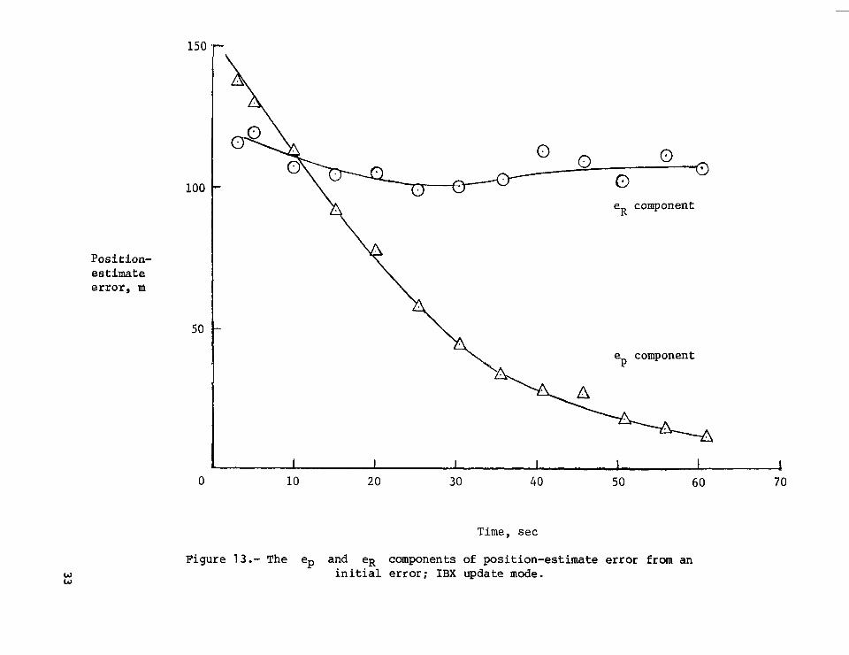
'Both t h e m a g n i t u d e a n d d i r e c t i o n of t h e p o s i t i o n - e s t i m a t e error vector were s t rong ly dependen t upon t h e i n i t i a l error when t h e IBX update mode s t a r t e d . C o r r e c t i o n s to t h e p o s i t i o n estimate were made o n l y i n a d i r e c t i o n p e r p e n d i c u l a r to t h e b a c k - a z i m u t h r a d i a l o n w h i c h t h e a i r p l a n e was l o c a t e d . N o c o r r e c t i o n s c o u l d be made i n a rad ia l d i r e c t i o n s i n c e DME s i g n a l i n p u t s were n o t a v a i l a b l e .
F i g u r e 13 shows t h e ep and eR error components €or a f l i g h t a l o n g t h e zero-azimuth radial . The IBX update mode was s t a r t e d w i t h i n i t i a l n a v i g a t i o n p o s i t i o n - e s t i m a t e errors of ep = 140 m and e~ = 11 8 m . The ep component was reduced because o f back-az lmuth s igna l inputs bu t the e R component r ema ined v i r tua l ly unchanged s ince no DME s i g n a l i n p u t s were a v a i l a b l e .
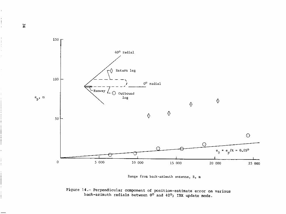
F i g u r e 14 shows the component as a f u n c t i o n of range when t h e a i r - p l a n e was f l m n a l o n g p a t h a n d b a c k to t h e s t a r t of p a t h 1 . The r e s u l t s were similar to t h o s e o b t a i n e d i n t h e IBD update mode: ee = 0.05O o n t h e zero-azimuth bear ing and eo I 0.25O o n t h e r e t u r n l e g .
I D D Update Mode
I n t h e I D D update mode, t h e p o s i t i o n - e s t i m a t e error v e c t o r was random i n d i r e c t i o n a n d h a d a mean magnitude of 183.5 m and a s t a n d a r d d e v i a t i o n of 81.1 m. T h e s e r e s u l t s are w i t h i n t h e 185-m a c c u r a c y t o l e r a n c e f o r DME ground s t a t i o n s a n d are similar t o past e x p e r i e n c e w i t h t h e d u a l DME update mode ( ref . 5 ) . I t is e x p e c t e d t h a t t h e u s e of PDME i n p u t s a l s o c o u l d i m p r o v e t h e
p o s i t i o n - e s t i m a t e a c c u r a c y i n t h e I D D update mode.
CONCLUDING REMARKS
F l i g h t tests w i t h t h e NASA Terminal Conf igured Vehic le (TCV) Boeing 737-100 a i rp l ane i n t he t ime- re fe renced s cann ing-beam (TRSB) microwave landing-system (MLS) environment have shown t h a t t h e a c c u r a c y of p o s i t i o n esti- mates based on dual dis tance-measuring-equipment (DME) i n p u t s c a n be improved by u s i n g MLS back-azimuth radio s i g n a l s . P o s i t i o n estimates from a combinat ion of back-azimuth and DME s i g n a l s a c h i e v e d t h e best pos i t i on -es t ima te accu racy . The next best accuracy was obta ined f rom back-az imuth s igna ls a lone . The leas t accu ra t e upda te mode o f t h e t h r e e t e s t e d was t h e d u a l DME mode.
The pos i t ion-es t imate accuracy was e s t a b l i s h e d by computing an error v e c t o r b e t w e e n t h e p o s i t i o n o f t h e a i r p l a n e d e f i n e d by ground-based radar t r a c k i n g a n d t h e a i r p l a n e p o s i t i o n estimated by t h e a i r p l a n e n a v i g a t i o n s y s t e m . This error v e c t o r was d i v i d e d i n t o two components: a component perpendicular
18
to the back-az imuth bear ing , in f luenced by back-azimuth s ignal inputs : and a component paral le l to the back -az imuth bea r ings , i n f luenced p r imar i ly by t he DME s i g n a l i n p u t s .
For updates us ing bo th DME and back-az imuth s igna l i npu t s , t he radial component of error c o n t r i b u t e d t h e l a r g e s t p o r t i o n to t h e error vec tor . The radial component of error was g e n e r a l l y c o n s t a n t as a f u n c t i o n of range f rom the back-azimuth antenna and was w i t h i n a c c u r a c y t o l e r a n c e s f o r t h i s DME s t a t i o n . T h e DME g r o u n d s t a t i o n u s e d d u r i n g t h e s e tests was a s t a n d a r d e n r o u t e n a v i g a t i o n s t a t i o n . The use of a p r e c i s i o n DME g r o u n d s t a t i o n p robab ly cou ld improve t he accu racy of t h e p o s i t i o n estimate.
The perpendicular component of error was in f luenced bo th by range from the back-az imuth an tenna and by the particular back-azimuth radial on which t h e a i r p l a n e was l o c a t e d .
For updates which used on ly the back-az imuth s igna l inputs , pos i t ion- estimate error was s t rong ly dependen t upon t h e i n i t i a l p o s i t i o n - e s t i m a t e error s i n c e c o r r e c t i o n s were made o n l y i n t h e p e r p e n d i c u l a r d i r e c t i o n . T h e perpendicular component of error showed a c c u r a c y c h a r a c t e r i s t i c s similar to those obse rved du r ing upda te s u s ing bo th DME and back-azimuth inputs.
For updates which used dual D m , p o s i t i o n - e s t i m a t e error was w i t h i n t h e a c c u r a c y t o l e r a n c e s p e c i f i e d f o r e n r o u t e DME and was similar t o p r e v i o u s e x p e r i e n c e w i t h d u a l DME updat ing . The accuracy of the p o s i t i o n estimate could be improved with the u s e of p r e c i s i o n DME s i g n a l i n p u t s .
Langley Research Center Nat iona l Aeronaut ics and Space A d m i n i s t r a t i o n Hampton, VA 23665 November 13, 1979
1 9
REFERENCES
1. Walsh, Thomas M.; and Weener, Earl F.: Automat ic F l igh t Pe r fo rmance o f a Transpor t Ai rp lane on Complex Microwave Landing System Paths. NASA Paper p re sen ted a t AGARD 25th GCP Symposium on Guidance and Control Design C o n s i d e r a t i o n s f o r Law A l t i t u d e and Terminal Area F l igh t (Day ton , Oh io ) , O c t . 1977.
2. Cosley, D.; and Mar t in , A. J.: ADEDS Funct ional /Software Requirements . SST Technology Follow-On Program - Phase 11. Rep. N o . FAA-SS-73-19, D e c . 1973. (Avai lable from DDC as AD BOO0 287.)
3. McKinstry, R. G i l l : Guidance Algori thms and Non-Cri t ical Control Laws f o r ADEDS and t h e AGCS Model NASA 515. Doc. D6-41565, Boeing Co., 1974.
4. Microwave Landing System Phase I1 Tracker Error Study. FAA Report No . FAA-RD-74-207, D X . 1974.
5. Knox, Char l e s E.: Expe r imen ta l De te rmina t ion o f t he Nav iga t ion Error of t h e 4-D Naviga t ion , Guidance , and Cont ro l Sys tems on the NASA B-737 A i r - p l ane . NASA Paper presented a t AGARD 25th GCP Symposium on Guidance and Cont ro l Des ign Cons idera t ions for Low A l t i t u d e and Terminal Area F l i g h t (Dayton, Ohio) , O c t . 1977.
6. Approval of Area Naviga t ion Sys tems for Use i n t h e U.S. Na t iona l A i r space System. AC No . 90-45A, FAA, Feb. 21, 1975.
20
I j
I
i I I !2
! !
Figure 1.- NASA terminal configured vehicle (TCV) research airplane.
NAV I GAT SENSORS
I ON
N A V I G A T I O N AND G U I D A N C E COMPUTE& - - - - ~ "_"""" - --- I
NAV I GAT PROGRAM
I I
I , THROTTLE P O S I T I O N
AUTOTHROTTLE SERVO
I ON GUIDANCE PROGRAM i P I T C H &
' I I
I F L I G H T CONTROL COMPUTERS
ROLL
I """_
-1 I I
NAV D I S P L A Y DATA COMPUTATIONS NCU
& I I I 1 I I """""""""_ - I I
PROGRAM CONTROL U N I T
"""_
Figure 2.- Functional block diagram of navigation, guidance, and control systems.
/ \
Back-azimuth / L F r o n t - a z i m u t h
+40° signal coverage / s igna l coverage
\ \
/ \ / +600 \ \ / \ \
/ \ /
Path 2
F i n a l l e g
Back-azmut antenna
/ /
/ /
/ /
:h
a,
\ \ Path 1 \ \ \
Figure 3 . - F l i g h t t es t p a t h s w i t h i n t h e MLS f r o n t - and back-azimuth s igna l coverage . Headings are r e l a t i v e to t r u e n o r t h .
Airplane estimated
Figure 4.- Geometry per ta ining to I B D update mode: back-azimuth antenna, DME, estimated and measured p o s i t i o n s of a i rp l ane , and runway wi th ex tended cen te r l i ne .
L a -
~~
Runway E
i A
b
Back-azimuth antenna, (bo, x.
Figure 5.- Vector Z,,t t r iangle components; IBD update mode. -k
25
Airplane position estimate, l e ) t-1
F igure 6.- Geometry per ta ining to IBX update mode: back-azimuth antenna locat ion, es t imated and measured azimuth posi t ions of a i r p l a n e , and runway with extended center l ine.
Back-azimuth
Figure 7.- La tera l and r a d i a l MLS back-azimuth geometry limits: W, L, and M.
Navigation position estimate
Position-estimate error vector e
Radar-defined position 3 P MLS
back-azimuth antenna
Figure 8.- Perpendicular and radial components of position-estimate error; ep, eR, and e0 are positive as shown.
, 40’ r a d i a l
F l igh t pa th
”””- 0’ r a d i a l Runway
6o t e m 40 P’
20
0 5 000 10 000 15 000 20 000
Range from back-azimuth antenna, R, m
Figure 9.- Perpendicular component of position-estimate error on t h e zero back-azimuth radial; IBD update mode.
w 0
150
100
e m P'
7
-
50 -
I
i
paths
0 0
0
0 8
0 8
0
0
8
eg = 0.05' - 0
rcI I I 1 1 1 0 5 000 10 000 15 000 20 000 25 000
Range from back-azimuth antenna, R, m
Figure 10.- Perpendicular component of position estimate error on various back-azimuth radials up to 40°; IBD update mode.
.4 1-
0 0 .3 "
A
.2
.1 c- 0
W N
2oo r 0 0
100
0
0
0
0 0
0 0
0
g) 0 -8 0
0 0
I I I I I 1
5 000 10 000 15 000 20 000 25 000
Range from back-azimuth antenna, R, m
Figure 12.- Radial component of position-estimate error; IBD update mode.
Position- estimate error, m
W W
150
100
50
0
e component R
e component P
10 20 30 40 50 60 70
Time , sec
Figure 13.- The ep and eR components of position-estimate error from an ini t ia l error ; IBX update mode.
e m P'
150
lOG
5c
40° radial
00 ""_ <-" -\
00
Runway z 0 Outbound radial
\ 0
0 0
0
0 0 n
1 . O P P e = e /R = 0.05O
I 1 I I 0 5 000 10 000 15 000 20 000 25 000
Range from back-azimuth antenna, R, m
Figure 14.- Perpendicular component of position-estimate error on various back-azimuth radials between Oo and 40°; IBX update mode.
1. Report No. NASA TP-1574 I 2. Government Accession No.
4. Title and Subtitle
EXPERIMENTAL DETERMINATION OF POSITION-ESTIMATE ACCURACY USING BACK-AZIMUTH SIGNALS FROM A MICROWAVE LANDING SYSTEM
7. Author(s)
Charles E. Knox
9. Performing Organization Name and Address
NASA Langley Research Center Hampton, VA 23665
2 . Sponsoring Agency Name and Address
National Aeronautics and Space Administration Washington, DC 20546
3. Recipient's Catalog No. ~ "
5. Report Date December 1979
6. Performing Organization Code
8. Performing Organization Report No. -
L-13074
10. Work Unit No.
51 3-52-1 3-62 11. Contract or Grant No
~~
13. Type of Report and Period Covered
Technical Paper
14. Sponsoring Agency Code - -~
5. Supplementary Notes
6. Abstract ~ "
This paper presents the results of flight tests using the NASA Terminal Configured Vehicle (TCV) Boeing 737 airplane to obtain position estimates with back-azimuth signals from a microwave landing system. The most accurate position estimates were obtained from a combination of back-azimuth and distance-measuring-equipment (ME) signals. Less accurate position estimates were obtained with back-azimuth signals alone; the least accurate position estimates were obtained with dual DME signals.
7. Key-Words (Suggested by Authoris))
Navigation Guidance Microwave landing system
9. Security Classif. (of this report) 20. Security Classif. (of this page) I 21. NO;; Pages " " - . - . - "
Unclassified Unclassified $4.50
18. Distribution Statement
Unclassified - Unlimited
Subject Category 04
*For sale by the National Technical Information Service, Springfield, Virpinla 22161 - NASA-Langley, 1979
I
National Aeronautics and Space Administration
Washington, D.C. 20546 Official Business
Penalty for Private Use, $300
THIRD-CLASS BULK RATE Postage and Fees Paid National Aeronautics and Space Administration NASA451 [Z) -
w n POSTMAS~ER: If Undeliverable (Section 158 Postal Manual) Do Not Return