Embed Size (px)
Citation preview
Experimental demonstration of single-channel EEG signal using 32 × 32 pixel OLED screen and camera
AGGARWAL, Geetika <http://orcid.org/0000-0002-8338-2504>, DAI, Xuewu <http://orcid.org/0000-0003-3540-2168>, SAATCHI, Reza <http://orcid.org/0000-0002-2266-0187>, BINNS, Richard and SIKANDAR, Ajay
Available from Sheffield Hallam University Research Archive (SHURA) at:
http://shura.shu.ac.uk/24783/
This document is the author deposited version. You are advised to consult the publisher's version if you wish to cite from it.
Published version
AGGARWAL, Geetika, DAI, Xuewu, SAATCHI, Reza, BINNS, Richard and SIKANDAR, Ajay (2019). Experimental demonstration of single-channel EEG signal using 32 × 32 pixel OLED screen and camera. Electronics, 8 (7), p. 734.
Copyright and re-use policy
See http://shura.shu.ac.uk/information.html
Sheffield Hallam University Research Archivehttp://shura.shu.ac.uk
electronics
Article
Experimental Demonstration of Single-Channel EEGSignal Using 32 × 32 Pixel OLED Screen and Camera
Geetika Aggarwal 1,* , Xuewu Dai 1 , Reza Saatchi 2 , Richard Binns 1 and Ajay Sikandar 3
1 Department of Mathematics, Physics and Electrical Engineering, Northumbria University,Newcastle Upon Tyne NE1 8ST, UK
2 Department of Engineering and Mathematics, Sheffield Hallam University, Sheffield S1 1WB, UK3 Department of Computer Science and Engineering, G L Bajaj Institute of Technology and Management,
Greater Noida 201306, India* Correspondence: [email protected]
Received: 27 April 2019; Accepted: 25 June 2019; Published: 28 June 2019�����������������
Abstract: Currently, the radiofrequency (RF)-based wireless technology deployed inelectroencephalography (EEG) to diagnose brain diseases suffers from frequency spectrum andelectromagnetic interference, and might also have adverse effects on the health of patients andequipment used in hospitals, especially in RF-restricted zones like intensive care units (ICUs). Opticalwireless communication (OWC), specifically visible light communication (VLC), is featured in 5Gnetwork to complement the radiofrequency (RF) technologies due to the fact that huge unlicensedbandwidth and available infrastructure, both indoor and outdoor, reduces the implementationcost. The conventional VLC systems deploy photodiodes as receivers, requiring hardware andinfrastructure modifications in addition to smaller field of view (FOV), but the use of camerasreduce the infrastructure cost due to inbuilt filters and a wider FOV coverage gives the ability toscale a larger area. The wider FOV and the movement of camera rotation, without any additionaladjustments to maintain the line-of-sight (LOS), allows the patient to be anywhere within the roomand FOV. This paper demonstrates a novel healthcare system for EEG using visible light opticalcamera communication (VL-OCC), where a 32 × 32 pixel OLED screen acts as transmitter and thereceiver section consists of several different cameras such as digital single-lens reflex camera (DLSR),android smartphone, and Thorlabs camera. The experiments were performed in LOS deployingon-off keying (OOK) modulation at several distant measurements to determine the system reliabilityand stability through bit error rate (BER) performance. The proposed system results depict that theDSLR camera outperforms the smartphone and Thorlabs cameras, as it is capable of transmitting anerror free bit rate of 2.8 kbps at 30 fps up to 5.5 m.
Keywords: visible light optical camera communication; organic light-emitting diode; 5G;healthcare; electroencephalography
1. Introduction
Electroencephalography (EEG), discovered in 1924 by Hans Berger, is a non-invasive procedure todiagnose brain diseases. The conventional EEG recording techniques are deployed by using severalscalp electrodes, which involves a long preparation time and are tedious. However, the growth ofwireless technology has led to wearable EEG headsets that are used for brain monitoring for specificapplications, such as Nuerosky, Imec, emotive, etc. [1]. Furthermore, the radiofrequency (RF)-basedtechnology, such as Bluetooth and ZigBee, are used in many EEG machines for data communication,but the RF technologies suffer from lack of frequency spectrum, eavesdropping, and electromagneticinterference [2–5]. VLC can be used for both for lighting and data communication hence, the use
Electronics 2019, 8, 734; doi:10.3390/electronics8070734 www.mdpi.com/journal/electronics
Electronics 2019, 8, 734 2 of 16
of LED lights, existing everywhere, for data communication is a cost-effective alternative to RFtechnology, specifically in hospitals and indoor environments [6–8]. In comparison to RF, the VLCspectrum is 10,000 times the RF spectrum, license free, and unregulated, hence it could be used for datacommunication [9]. VLC deploys light waves for communication, which are insensitive to electronicequipment; therefore, free from electromagnetic interference and thus best suited in healthcareapplications, especially in RF-restricted areas such as intensive care units (ICUs) [10,11]. Since the lightsare easily blocked by non-transparent object such as walls, hence visible light communication is moresecure in comparison to RF, infrared (IR) and ultraviolet (UV) communications [12]. Additionally, thelight confines the information to optics and within the premises of a VLC-based system, hence VLC doesnot suffer from eavesdropping [13]. Hence, in past years, several studies were conducted on visible lightcommunication in different areas of research, such as indoor positioning [6,13–16], vehicle-to-vehiclecommunication [7,17–19], environmental monitoring [8,20], and IoT applications [21,22]. It is due tothe capability of providing both illumination and data communication unlike other OWC systems.
Nowadays, in VLC systems, the organic light-emitting diode (OLED) is replacing theconventionally-used transmitter, such as the white LED, because of low cost and flexibility [9,10];however, the VLC-based LEDs/OLED systems employ a photodiode (PD) as the receiver (Rx). The VLCsystems deploying a conventional PD as the receiver requires hardware modifications due to additionalfilters and amplifier circuitry; therefore, in order to provide low-cost flexible wireless communications,a camera is the best solution to be deployed as the receiver in VLC systems [10,11]. Cameras areubiquitous and increasingly being used not just for capturing images but also for communicatinginformation. The universal access of Quick Response Code (QR) codes motivates deploying novelcamera communication applications, where pervasive display screens could be modulated to send timevarying QR codes to be decoded by video cameras. The pixel elements of the screen and camera can beleveraged to send data through time-varying 2D barcodes [11–13]. Optical camera communication is arecent development of OWC and an extension of VLC, where image sensors or cameras are used forsensing the light intensity emitted from a light emitter instead of conventional photodiodes. Opticalcamera communication (OCC) is a pragmatic version of visible light communication (VLC) using acamera as the receiver. OCC operates in the same channel band as VLC with more advantages onreceiver characteristics and has been studied in the IEEE 802.15 SG7a within the framework of opticalwireless communications and considered as a candidate of IEEE 802.15.7rl [12–14]. The OCC has aninherent advantage of capturing 2-dimensional (2D) image data, compared with intensity level-basedphotodiodes in VLC [12]. The popularity of smart devices and the camera installed in every smartdevice has resulted in the use of a camera as a receiver for communication purposes in VLC systems.In conventional VLC systems, PD is the receiver which requires hardware modification due to filtersand amplifiers; however, with the receiver being the camera the cost of implementation is considerablyreduced due to inbuilt filters and focusing properties, reducing the unwanted noise [12,13]. BitError Rate (BER) is calculated by comparing the transmitted and received data bits through imagessuch as The QR code obtained at receiver section through image capture can be easily compared tothe transmitted image in 2D to calculate BER and to analyse the system performance. The severalmodulation and demodulation techniques of VLC are used for OCC, as OCC is an extension of VLC,hence the modulation techniques of VLC can be easily incorporated on visible light optical cameracommunication (VL-OCC).
The VL-OCC aims to use commercial LED- or OLED-based infrastructure lighting as the transmitter,and the receiver being the camera. The VL-OCC technology employing the OLED screen as transmitterand the camera as receiver is believed to play an important role in the provision of internet of thing (IoT)and the 5G wireless network [13,14]. Furthermore, the camera focussing ability mitigates the blurringand the inbuilt filters automatically filter the unwanted noise, without any infrastructure modificationsunlike conventional VLC systems that have a PD as the receiver. The concept of transmitting a 1Dsignal in the digitized form using the On-Off Keying Non-Return to Zero (OOK-NRZ) modulationscheme in a 2D image, with an OLED screen as transmitter and a camera as receiver makes VLC an
Electronics 2019, 8, 734 3 of 16
good alternative to RF communications for data transmission. The adverse impacts of RF signals onhuman wellbeing and interferences to other medical electronic devices have been in particularly inhospitals. Moreover, it has been stated by the World Health Organization that RF has the possibility ofcausing cancer in humans [10–13]. The fact that VLC is more friendly to human and medical electronicsis one of the main advantages of using VLC in medicinal services or healthcare. Therefore, this researchwork proposes a novel VL-OCC-based wireless healthcare system for EEG, using the screen of an OLEDas the transmitter and a camera as the receiver. Experiments were carried out in line of sight (LOS)using on-off keying non return to zero (OOK_NRZ) modulation in a realistic medical scenario, withthe patient being in the vicinity of the field of view (FOV) of the camera. The camera, having a widerFOV than conventional photodiodes, can scan a larger area, hence the patient can be anywhere withinthe room. Furthermore, rotating the camera to maintain the LOS is easily feasible, unlike conventionalVLC systems deploying photodiodes. The proposed system’s experimental results of transmitting theEEG signal in 1D to a 2D image shows that that the system can communicate up to distance of 5.5 m ata camera frame rate of 30 fps, achieving a bit rate of 2.8 kbps.
Our contribution: There are three main contributions in this research paper.
• The link distance of 5.5 m is achieved, in comparison to the results of available literature of EEGand VLC.
• The proposed system will be beneficial in the healthcare environment, such as hospitals, wherethe RF technology is expensive and suffers from Electromagnetic Interference (EMI).
• Due to bit rate being limited by camera frame rate, the achievable rate in the proposed researchwork in this paper is 2.8 kbps. The bit rate of 2.8 kbps is enough to transmit single-channel EEGtransmission using VL-OCC.
The remaining paper is divided into different sections: Section 2 lists the related works; Section 3narrates the system architecture and applications of VL-OCC; Section 4 illustrates the proposed systemmodel for EEG using VL-OCC; Section 5 the experimental work with results; and the conclusion islisted in Section 6.
2. Related Works
Here, the related work is divided into two sub sections. In Section 2.1, we list the present EEGprocedure in hospitals and the commercial RF-based EEG products, and in Section 2.2 we list therelated work on visible light communication for EEG.
2.1. Current EEG Procedure in Hospitals and RF-Based EEG Products
The current EEG procedure in hospitals involved deployed wet electrodes, thus resulting in longpreparation time, which was not only tedious and time consuming but also resulted in discomfort topatients [23]. In context, to overcome the problem of wet electrodes, several researchers moved to dryelectrodes for EEG brain monitoring. The authors in [24] mentioned that, in comparison to traditionalEEG brain monitoring, existing EEG wireless devices deploy dry electrodes; however, a direct linkbetween the scalp and electrodes is prevented by hair, thus resulting the path being obstructed in EEGsignal measurement. Usually, the conventional silver–silver chloride electrodes with conductive gelswere used to record EEG; however, conductive gels can dry and become hard over long-term EEGmonitoring. Therefore, the EEG signal captured is not accurate due to there being no proper contactbetween the scalp and the electrode [25]. In [26], the authors proposed a comb-shaped electrode,whereby the hair could be easily moved, hence the electrode could easily reach the scalp, thus providingaccurate EEG monitoring. However, it was only deployed in brain computer applications. The authorsin [27] employed metal pogo probes for brain monitoring; despite high precision the dry sensors causeddiscomfort to users after several hours. The single-channel EEG monitoring was proposed by authorsin [28], using Bluetooth technology to transmit data wirelessly whereby the single cylindrically-shapedelectrode was used for brain monitoring. However, RF technology using systems like Bluetooth and
Electronics 2019, 8, 734 4 of 16
Zigbee for wireless transmission affect system performance in RF sensitive areas, such as hospitals,aircrafts, etc., due to electromagnetic interference. The authors in [29] deployed in-ear sensors for brainmonitoring; however, despite of the low-input impedance of the sensors, were unable to provide acomprehensive study of the brain.
The pathway between a computer device and the brain is known as the brain–computer interface(BCI) [30,31]. Neurosky is most commonly used in BCI and is based on one channel measurementusing dry electrodes. It is used to study a specific section or part of the brain [32]. Another mostcommonly-used EEG product is Emotiv, which provides 12 h continuous wireless transmission througha radio. However, the continuous monitoring for 12 h using RF technology might have adverse effectson patients’ health due to electromagnetic interference [33]. The EEG product designed by authorsin [34] is G.Nautilus, and is a lightweight device that is preferred for the comprehensive study of thebrain due to EEG recordings from several channels. Mindo-4 is another BCI EEG product mainlydeployed in gaming applications and to measure sleep disorders, and it has a weight of 250 g anda battery life of 10 h. The dry sensors are preferred in EEG, in comparison to wet sensors, due tothe long preparation time of wet sensors and them being uncomfortable for patients [35]. In orderto measure the mood in people, Cognionics or Quick 20 is widely used, operating wirelessly at afrequency ranging from 0–131 Hz at 500 samples/s with 64 channels, and at a frequency ranging from0–262 Hz at 1000 samples/s with 32 channels [36]. Enobio, another EEG wearable system, is preferredfor the recording of EEG, which is best for applications such as sleep studies [37].
The applications of EEG devices vary, and the selection of EEG products depends upon therequirement of individual applications with consideration of following key parameters such assampling rate, resolution, battery life and number of electrodes. For example, for brain monitoring, ifthe number of channels required is 1, and a bandwidth ranging between 3–100 Hz at a sampling rate of512 Hz and battery life of 8 h is needed, Neurosky is the best choice [32]. These wireless RF-based EEGproducts are used in EEG for certain applications, but none of them has been considerably deployed inhospitals due to electromagnetic interference. In order to overcome the above-illustrated problems ofcurrent RF-based wireless wearable EEG systems in RF sensitive areas, the proposed EEG systemsmust be EMI free, unlike the traditional systems which are tedious, wired, have EMI, and providediscomfort to patients [4,38]. In view of the shortcomings of EEG products based on RF technology,VLC is the promising solution due to low implementation cost, security, no eavesdropping, and beingfree from EMI [12].
2.2. Recent Work on Visible Light Communication for EEG
VLC has been extensively used in areas such as vehicle-to-vehicle communication, Light -Fidelity(Li-FI), underwater applications, and military applications, but the research work of VLC for EEG inhealthcare has just begun over the past few years [5]. In healthcare applications, specifically EEG,due to low cost, being free from EMI, and reliability, several researchers have moved to VLC fromRF technology. In the VLC system, the transmitter can be LED, or OLED, and the receiver can bea photodiode or a camera. Due to the low data rate limit of cameras, photodiodes are deployedas receivers in VLC systems; however, this option does require hardware modifications. Severalresearchers have proposed their VLC system for EEG signal transmission comprising of both types oftransmitters and receivers.
In [3], a VLC system deploying a LED/PD pair of RGB (red, green and blue) achieved a data rateof 4 kbps at a distance of 50 cm for EEG signal transmission. However, an array of three transmittersand three photodiodes were used to transmit and receive the EEG signal, hence added towards the costand hardware modifications. The authors in [39] proposed a brain health monitoring system based onSupport Vector Machine (SVM) for daily monitoring using Bluetooth, an RF protocol suffering fromEMI and not applicable in RF sensitive areas. The authors in [40] achieved a data rate of 2 kbps usingVL-OCC for EEG signal transmission; however, the distance achieved was 50 cm. In [41], authorsdemonstrated a wearable EEG system using a single electrode based on a mobile phone VLC, achieving
Electronics 2019, 8, 734 5 of 16
a data rate of 2.4 kbps using a modulation scheme of OOK. The EEG signal was successfully transmittedover 4 m using a mobile as the receiver and LED as the transmitter.
The authors in this paper proposed a LOS, single-channel, EEG data transmission system usingan OLED screen as the transmitter and a camera as the receiver. The VL-OCC system architecture andapplications are listed in the next section.
3. VL-OCC System Architecture and Applications
In the VLC structure LEDs are deployed for the dual purposes of lighting and communication. OCCis one of the promising technologies of OWC, whereby the light intensity of LED or OLED is modulatedto transmit the data, but the receiver is a camera instead of photodiodes, unlike traditional VLC systems,and; thus, requires almost no additional implementation cost and hardware modifications [42–45].
3.1. Brief Description of the VLC System
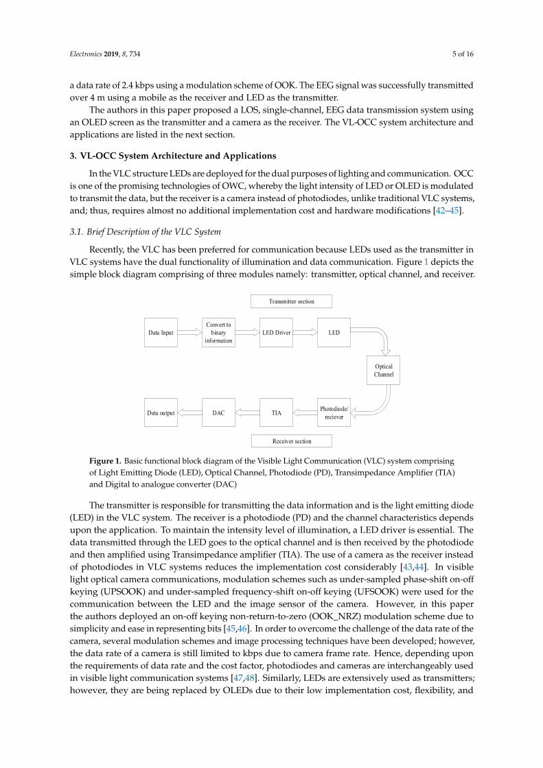
Recently, the VLC has been preferred for communication because LEDs used as the transmitter inVLC systems have the dual functionality of illumination and data communication. Figure 1 depicts thesimple block diagram comprising of three modules namely: transmitter, optical channel, and receiver.
Electronics 2019, 8, x FOR PEER REVIEW 5 of 16
VLC, achieving a data rate of 2.4 kbps using a modulation scheme of OOK. The EEG signal was successfully transmitted over 4 m using a mobile as the receiver and LED as the transmitter.
The authors in this paper proposed a LOS, single-channel, EEG data transmission system using an OLED screen as the transmitter and a camera as the receiver. The VL-OCC system architecture and applications are listed in the next section.
3. VL-OCC System Architecture and Applications
In the VLC structure LEDs are deployed for the dual purposes of lighting and communication. OCC is one of the promising technologies of OWC, whereby the light intensity of LED or OLED is modulated to transmit the data, but the receiver is a camera instead of photodiodes, unlike traditional VLC systems, and; thus, requires almost no additional implementation cost and hardware modifications [42–45].
3.1. Brief Description of the VLC System
Recently, the VLC has been preferred for communication because LEDs used as the transmitter in VLC systems have the dual functionality of illumination and data communication. Figure 1 depicts the simple block diagram comprising of three modules namely: transmitter, optical channel, and receiver.
Data InputConvert to
binary information
LED Driver LED
Photodiode/recieverTIADACData output
Optical Channel
Transmitter section
Receiver section Figure 1. Basic functional block diagram of the Visible Light Communication (VLC) system comprising of Light Emitting Diode (LED), Optical Channel, Photodiode (PD), Transimpedance Amplifier (TIA) and Digital to analogue converter (DAC)
The transmitter is responsible for transmitting the data information and is the light emitting diode (LED) in the VLC system. The receiver is a photodiode (PD) and the channel characteristics depends upon the application. To maintain the intensity level of illumination, a LED driver is essential. The data transmitted through the LED goes to the optical channel and is then received by the photodiode and then amplified using Transimpedance amplifier (TIA). The use of a camera as the receiver instead of photodiodes in VLC systems reduces the implementation cost considerably [43,44]. In visible light optical camera communications, modulation schemes such as under-sampled phase-shift on-off keying (UPSOOK) and under-sampled frequency-shift on-off keying (UFSOOK) were used for the communication between the LED and the image sensor of the camera. However, in this paper the authors deployed an on-off keying non-return-to-zero (OOK_NRZ) modulation scheme due to simplicity and ease in representing bits [45,46]. In order to overcome the challenge of the data rate of the camera, several modulation schemes and image processing techniques have been developed; however, the data rate of a camera is still limited to kbps due to camera frame rate. Hence, depending upon the requirements of data rate and the cost factor, photodiodes and cameras are interchangeably used in visible light communication systems [47,48]. Similarly, LEDs are extensively used as transmitters; however, they are being replaced by OLEDs due to their low implementation
Figure 1. Basic functional block diagram of the Visible Light Communication (VLC) system comprisingof Light Emitting Diode (LED), Optical Channel, Photodiode (PD), Transimpedance Amplifier (TIA)and Digital to analogue converter (DAC)
The transmitter is responsible for transmitting the data information and is the light emitting diode(LED) in the VLC system. The receiver is a photodiode (PD) and the channel characteristics dependsupon the application. To maintain the intensity level of illumination, a LED driver is essential. Thedata transmitted through the LED goes to the optical channel and is then received by the photodiodeand then amplified using Transimpedance amplifier (TIA). The use of a camera as the receiver insteadof photodiodes in VLC systems reduces the implementation cost considerably [43,44]. In visiblelight optical camera communications, modulation schemes such as under-sampled phase-shift on-off
keying (UPSOOK) and under-sampled frequency-shift on-off keying (UFSOOK) were used for thecommunication between the LED and the image sensor of the camera. However, in this paperthe authors deployed an on-off keying non-return-to-zero (OOK_NRZ) modulation scheme due tosimplicity and ease in representing bits [45,46]. In order to overcome the challenge of the data rate of thecamera, several modulation schemes and image processing techniques have been developed; however,the data rate of a camera is still limited to kbps due to camera frame rate. Hence, depending uponthe requirements of data rate and the cost factor, photodiodes and cameras are interchangeably usedin visible light communication systems [47,48]. Similarly, LEDs are extensively used as transmitters;however, they are being replaced by OLEDs due to their low implementation cost, flexibility, and
Electronics 2019, 8, 734 6 of 16
low-power consumption. In this research work, low data rate was the requirement for the transmissionof single-channel EEG in LOS condition. The authors were able to achieve the data rate of 2.8 kbpsfor EEG using VLC and a camera in comparison with the maximum data rate of 2.4 kbps reported inliterature, the proposed scheme performed better with data rate being improved by 16%.
3.2. VL-OCC System Architecture
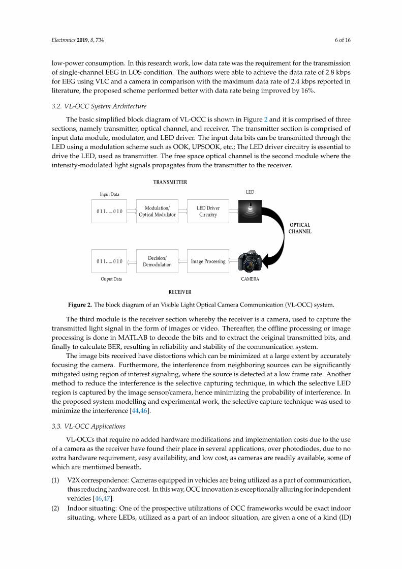
The basic simplified block diagram of VL-OCC is shown in Figure 2 and it is comprised of threesections, namely transmitter, optical channel, and receiver. The transmitter section is comprised ofinput data module, modulator, and LED driver. The input data bits can be transmitted through theLED using a modulation scheme such as OOK, UPSOOK, etc.; The LED driver circuitry is essential todrive the LED, used as transmitter. The free space optical channel is the second module where theintensity-modulated light signals propagates from the transmitter to the receiver.
Electronics 2019, 8, x FOR PEER REVIEW 6 of 16
cost, flexibility, and low-power consumption. In this research work, low data rate was the requirement for the transmission of single-channel EEG in LOS condition. The authors were able to achieve the data rate of 2.8 kbps for EEG using VLC and a camera in comparison with the maximum data rate of 2.4 kbps reported in literature, the proposed scheme performed better with data rate being improved by 16%.
3.2. VL-OCC System Architecture
The basic simplified block diagram of VL-OCC is shown in Figure 2 and it is comprised of three sections, namely transmitter, optical channel, and receiver. The transmitter section is comprised of input data module, modulator, and LED driver. The input data bits can be transmitted through the LED using a modulation scheme such as OOK, UPSOOK, etc.; The LED driver circuitry is essential to drive the LED, used as transmitter. The free space optical channel is the second module where the intensity-modulated light signals propagates from the transmitter to the receiver.
0 1 1…...0 1 0 Modulation/Optical Modulator
LED Driver Circuitry
TRANSMITTER
Input Data
0 1 1…...0 1 0 Decision/Demodulation Image Processing
Ouput Data
LED
CAMERA
OPTICAL CHANNEL
RECEIVER
Figure 2. The block diagram of an Visible Light Optical Camera Communication (VL-OCC) system.
The third module is the receiver section whereby the receiver is a camera, used to capture the transmitted light signal in the form of images or video. Thereafter, the offline processing or image processing is done in MATLAB to decode the bits and to extract the original transmitted bits, and finally to calculate BER, resulting in reliability and stability of the communication system.
The image bits received have distortions which can be minimized at a large extent by accurately focusing the camera. Furthermore, the interference from neighboring sources can be significantly mitigated using region of interest signaling, where the source is detected at a low frame rate. Another method to reduce the interference is the selective capturing technique, in which the selective LED region is captured by the image sensor/camera, hence minimizing the probability of interference. In the proposed system modelling and experimental work, the selective capture technique was used to minimize the interference [44,46].
3.3. VL-OCC Applications
VL-OCCs that require no added hardware modifications and implementation costs due to the use of a camera as the receiver have found their place in several applications, over photodiodes, due to no extra hardware requirement, easy availability, and low cost, as cameras are readily available, some of which are mentioned beneath.
(1) V2X correspondence: Cameras equipped in vehicles are being utilized as a part of communication, thus reducing hardware cost. In this way, OCC innovation is exceptionally alluring for independent vehicles [46,47].
Figure 2. The block diagram of an Visible Light Optical Camera Communication (VL-OCC) system.
The third module is the receiver section whereby the receiver is a camera, used to capture thetransmitted light signal in the form of images or video. Thereafter, the offline processing or imageprocessing is done in MATLAB to decode the bits and to extract the original transmitted bits, andfinally to calculate BER, resulting in reliability and stability of the communication system.
The image bits received have distortions which can be minimized at a large extent by accuratelyfocusing the camera. Furthermore, the interference from neighboring sources can be significantlymitigated using region of interest signaling, where the source is detected at a low frame rate. Anothermethod to reduce the interference is the selective capturing technique, in which the selective LEDregion is captured by the image sensor/camera, hence minimizing the probability of interference. Inthe proposed system modelling and experimental work, the selective capture technique was used tominimize the interference [44,46].
3.3. VL-OCC Applications
VL-OCCs that require no added hardware modifications and implementation costs due to the useof a camera as the receiver have found their place in several applications, over photodiodes, due to noextra hardware requirement, easy availability, and low cost, as cameras are readily available, some ofwhich are mentioned beneath.
(1) V2X correspondence: Cameras equipped in vehicles are being utilized as a part of communication,thus reducing hardware cost. In this way, OCC innovation is exceptionally alluring for independentvehicles [46,47].
(2) Indoor situating: One of the prospective utilizations of OCC frameworks would be exact indoorsituating, where LEDs, utilized as a part of an indoor situation, are given a one of a kind (ID)

Electronics 2019, 8, 734 7 of 16
code, and a smartphone or laptop with an inherent camera can be utilized to viably find gadgetsand individuals inside a room [48].
(3) Computerized signage: Presently advanced/digital signage has turned into the most well-knownmedium among organizations for broadcasting or offering coupons to clients. Watchersmight utilize their cell phones to get data from advanced signage, hence providing ongoingscreen-to-camera correspondence behind the scenes [49,50].
Due to the several advantages and applications of OCC, over photodiodes, in VLC systems,VL-OCC is preferred where the camera is the receiver, thus reducing the hardware cost and enhancingthe mobility and flexibility to secure wireless communication technology.
4. Proposed EEG VL-OCC System Modelling
This section explains the system modelling of the proposed VL-OCC for EEG. Figure 3 shows theproposed system modelling in healthcare for EEG. The data bits transmitted are presented by bn.
Electronics 2019, 8, x FOR PEER REVIEW 7 of 16
(2) Indoor situating: One of the prospective utilizations of OCC frameworks would be exact indoor situating, where LEDs, utilized as a part of an indoor situation, are given a one of a kind (ID) code, and a smartphone or laptop with an inherent camera can be utilized to viably find gadgets and individuals inside a room [48].
(3) Computerized signage: Presently advanced/digital signage has turned into the most well-known medium among organizations for broadcasting or offering coupons to clients. Watchers might utilize their cell phones to get data from advanced signage, hence providing ongoing screen-to-camera correspondence behind the scenes [49,50].
Due to the several advantages and applications of OCC, over photodiodes, in VLC systems, VL-OCC is preferred where the camera is the receiver, thus reducing the hardware cost and enhancing the mobility and flexibility to secure wireless communication technology.
4. Proposed EEG VL-OCC System Modelling
This section explains the system modelling of the proposed VL-OCC for EEG. Figure 3 shows the proposed system modelling in healthcare for EEG. The data bits transmitted are presented by 𝑏 .
Figure 3. Proposed Visible Light Optical Camera Communication (VL-OCC) system model.
The OLED screen working as a transmitter is a matrix of LEDs arranged in the formation of rows and columns. The total number of LEDs is 𝑁 = 𝑅 × 𝐶 . Thereafter the signal extracted from the microprocessor and fed to the OLED screen after serial to parallel conversion (S/P) is given by 𝑠( ) =[𝑟 ,𝑐 ]. The spatial discrete coordinates were presented in the OLED screen as rows and columns given by 𝑟 and 𝑐 , respectively. The number of bits that were transmitted per frame of the OLED screen was dependent upon the size of pixels; D given by (𝑆 /𝐷) × (𝑆 /𝐷) = 𝑅 × 𝐶 (1)
where 𝑆 and 𝑆 are rows and columns number, respectively. The optical signal transmitted from the OLED screen can be presented by 𝑥( )[𝑟 ,𝑐 ] = (𝑠 ∗ ℎ)( )[𝑟 ,𝑐 ] (2)
In Equation (2), h is the impulse response and Equation (3) presents the received signal given by 𝑦( )[𝑟 ,𝑐 ] = (𝑥)( )[𝑟 ,𝑐 ] + (𝑣)( )[𝑟 ,𝑐 ] (3)
Figure 3. Proposed Visible Light Optical Camera Communication (VL-OCC) system model.
The OLED screen working as a transmitter is a matrix of LEDs arranged in the formation of rowsand columns. The total number of LEDs is N = R1 × C1. Thereafter the signal extracted from themicroprocessor and fed to the OLED screen after serial to parallel conversion (S/P) is given by s(t) = [r1,c1]. The spatial discrete coordinates were presented in the OLED screen as rows and columns given byr1 and c1, respectively. The number of bits that were transmitted per frame of the OLED screen wasdependent upon the size of pixels; D given by
(Szrow /D) × (Szcolumn /D) = R1 ×C1 (1)
where Szrow and Szcolumn are rows and columns number, respectively. The optical signal transmitted fromthe OLED screen can be presented by
x(t)[r1, c1]= (s ∗ h)(t)[r1, c1 ] (2)
In Equation (2), h is the impulse response and Equation (3) presents the received signal given by
y(t)[r1, c1]= (x)(t)[r1, c1 ]+(v)(t)[r1, c1] (3)
Electronics 2019, 8, 734 8 of 16
where (v)(t)[r1, c1] is the dominant white Gaussian noise (WGN) and was independent of the pixels.Thereafter, the camera was used to capture a video, which was followed by processing of images andthreshold detection in MATLAB, to decode the images and bits, to get the original EEG signal and tocalculate BER. The nomenclature is listed in Table 1.
Table 1. Nomenclature.
Notation Description
N Total number of data bits which are transmitted through amatrix of rows and columns on the transmitter OLED screen
D Size of pixelR1 Rows per frame as per value of DC1 Columns per frame as per value of Dbn Transmitted bits before S/P
s(t)dimensional signal formed because of rows and columns of
OLED screen, transmitted after S/P in t (the time frame)y(t) Received dimensional signal from camera
Additive white noise, noise realizationSignal represented at optical channel
S/P and P/S Serial to parallel conversion and parallel to serial conversion,respectively
Fps Frames per second
The bits transmitted through the OLED screen were received by the camera at different distancesto calculate the BER and to depict the successful transmission of the EEG signal. The video captured bycamera was downloaded to MATLAB using a USB cable or memory card; thereafter offline processingwas done to determine the BER at different distances. In the experiment, the ambient light was keptvery low to avoid interference to the receiver.
5. Experiments and Results
This section is subdivided into three different modules. Section 5.1 lists the extraction of the EEGsignal from the EEGLAB Open Source Matlab Toolbox and the signal processing of the EEG signal inMATLAB. Section 5.2 explains the experimental work and hardware description, while the results arelisted in Section 5.3.
5.1. Extraction of EEG Signal from EEGtoolbox
This section illustrates EEG signal extraction from EEGLAB Open Source Matlab Toolbox followedby pre-signal processing.
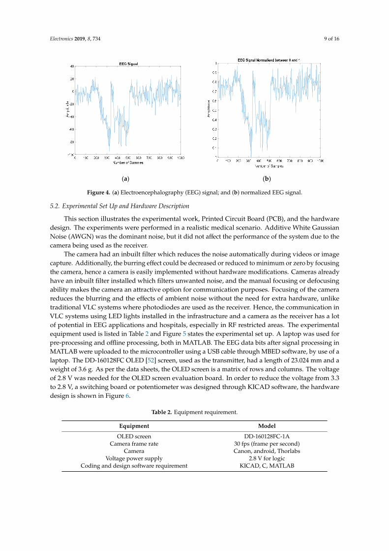
Initially, the EEG signal was obtained from the EEGLAB Open Source Matlab Toolbox known asEEGlab. The EEGlab is a software designed by researchers in the US to extract the EEG signals usingMATLAB and to use these EEG signals for laboratory research work [51]. The signal obtained fromEEGlab using MATLAB is shown in Figure 4a. The EEG signal had an amplitude of millivolts and thenumber of samples taken in our experimental work were 1000 for transmission. The optical channeltransmits the optical intensity, which cannot be negative, hence the EEG signal was normalized in therange of 0 to 1, as shown in Figure 4b. Thereafter, the signal obtained in digital form was up-sampledfor optical transmission to aid in reconstruction of the original signal transmitted at the receiver (laterstage). Then the useful bits obtained were transferred to the microcontroller using a USB cable.
Electronics 2019, 8, 734 9 of 16Electronics 2019, 8, x FOR PEER REVIEW 9 of 16
(a) (b)
Figure 4. (a) Electroencephalography (EEG) signal; and (b) normalized EEG signal.
5.2. Experimental Set Up and Hardware Description
This section illustrates the experimental work, Printed Circuit Board (PCB), and the hardware design. The experiments were performed in a realistic medical scenario. Additive White Gaussian Noise (AWGN) was the dominant noise, but it did not affect the performance of the system due to the camera being used as the receiver.
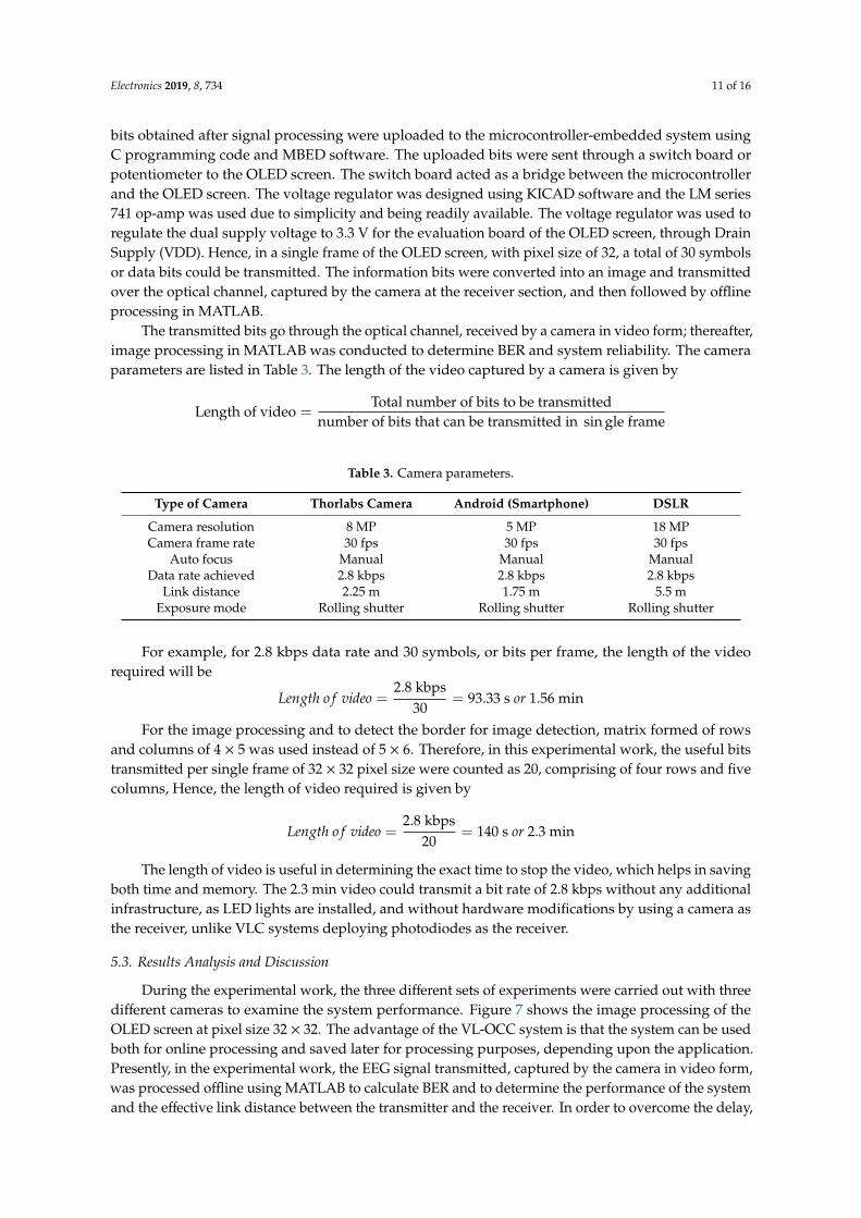
The camera had an inbuilt filter which reduces the noise automatically during videos or image capture. Additionally, the burring effect could be decreased or reduced to minimum or zero by focusing the camera, hence a camera is easily implemented without hardware modifications. Cameras already have an inbuilt filter installed which filters unwanted noise, and the manual focusing or defocusing ability makes the camera an attractive option for communication purposes. Focusing of the camera reduces the blurring and the effects of ambient noise without the need for extra hardware, unlike traditional VLC systems where photodiodes are used as the receiver. Hence, the communication in VLC systems using LED lights installed in the infrastructure and a camera as the receiver has a lot of potential in EEG applications and hospitals, especially in RF restricted areas. The experimental equipment used is listed in Table 2 and Figure 5 states the experimental set up. A laptop was used for pre-processing and offline processing, both in MATLAB. The EEG data bits after signal processing in MATLAB were uploaded to the microcontroller using a USB cable through MBED software, by use of a laptop. The DD-160128FC OLED [52] screen, used as the transmitter, had a length of 23.024 mm and a weight of 3.6 g. As per the data sheets, the OLED screen is a matrix of rows and columns. The voltage of 2.8 V was needed for the OLED screen evaluation board. In order to reduce the voltage from 3.3 to 2.8 V, a switching board or potentiometer was designed through KICAD software, the hardware design is shown in Figure 6.
Table 2. Equipment requirement.
Equipment MODEL OLED screen DD-160128FC-1A
Camera frame rate 30 fps (frame per second) Camera Canon, android, Thorlabs
Voltage power supply 2.8 V for logic Coding and design software requirement KICAD, C, MATLAB
Figure 4. (a) Electroencephalography (EEG) signal; and (b) normalized EEG signal.
5.2. Experimental Set Up and Hardware Description
This section illustrates the experimental work, Printed Circuit Board (PCB), and the hardwaredesign. The experiments were performed in a realistic medical scenario. Additive White GaussianNoise (AWGN) was the dominant noise, but it did not affect the performance of the system due to thecamera being used as the receiver.
The camera had an inbuilt filter which reduces the noise automatically during videos or imagecapture. Additionally, the burring effect could be decreased or reduced to minimum or zero by focusingthe camera, hence a camera is easily implemented without hardware modifications. Cameras alreadyhave an inbuilt filter installed which filters unwanted noise, and the manual focusing or defocusingability makes the camera an attractive option for communication purposes. Focusing of the camerareduces the blurring and the effects of ambient noise without the need for extra hardware, unliketraditional VLC systems where photodiodes are used as the receiver. Hence, the communication inVLC systems using LED lights installed in the infrastructure and a camera as the receiver has a lotof potential in EEG applications and hospitals, especially in RF restricted areas. The experimentalequipment used is listed in Table 2 and Figure 5 states the experimental set up. A laptop was used forpre-processing and offline processing, both in MATLAB. The EEG data bits after signal processing inMATLAB were uploaded to the microcontroller using a USB cable through MBED software, by use of alaptop. The DD-160128FC OLED [52] screen, used as the transmitter, had a length of 23.024 mm and aweight of 3.6 g. As per the data sheets, the OLED screen is a matrix of rows and columns. The voltageof 2.8 V was needed for the OLED screen evaluation board. In order to reduce the voltage from 3.3to 2.8 V, a switching board or potentiometer was designed through KICAD software, the hardwaredesign is shown in Figure 6.
Table 2. Equipment requirement.
Equipment Model
OLED screen DD-160128FC-1ACamera frame rate 30 fps (frame per second)
Camera Canon, android, ThorlabsVoltage power supply 2.8 V for logic
Coding and design software requirement KICAD, C, MATLAB
Electronics 2019, 8, 734 10 of 16
Electronics 2019, 8, x FOR PEER REVIEW 10 of 16
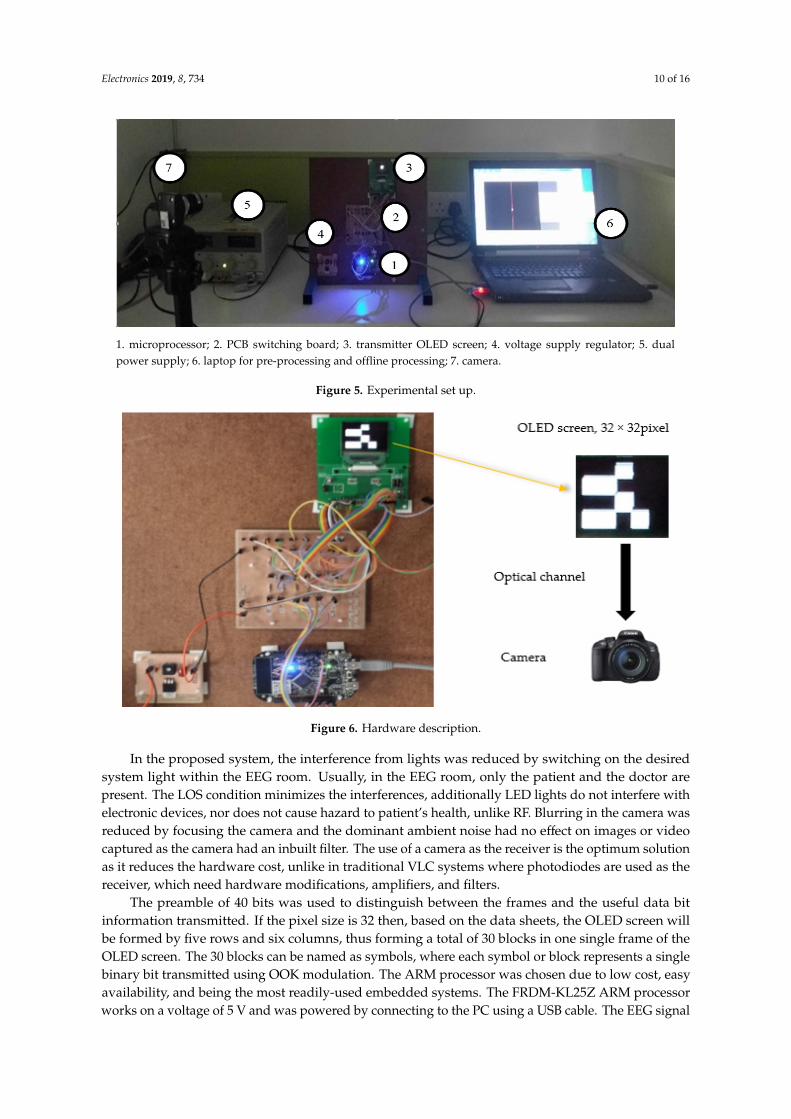
1. microprocessor; 2. PCB switching board; 3. transmitter OLED screen; 4. voltage supply regulator; 5. dual power supply; 6. laptop for pre-processing and offline processing; 7. camera.
Figure 5. Experimental set up.
In the proposed system, the interference from lights was reduced by switching on the desired system light within the EEG room. Usually, in the EEG room, only the patient and the doctor are present. The LOS condition minimizes the interferences, additionally LED lights do not interfere with electronic devices, nor does not cause hazard to patient’s health, unlike RF. Blurring in the camera was reduced by focusing the camera and the dominant ambient noise had no effect on images or video captured as the camera had an inbuilt filter. The use of a camera as the receiver is the optimum solution as it reduces the hardware cost, unlike in traditional VLC systems where photodiodes are used as the receiver, which need hardware modifications, amplifiers, and filters.
Figure 6. Hardware description.
The preamble of 40 bits was used to distinguish between the frames and the useful data bit information transmitted. If the pixel size is 32 then, based on the data sheets, the OLED screen will be formed by five rows and six columns, thus forming a total of 30 blocks in one single frame of the OLED screen. The 30 blocks can be named as symbols, where each symbol or block represents a single binary bit transmitted using OOK modulation. The ARM processor was chosen due to low cost, easy availability, and being the most readily-used embedded systems. The FRDM-KL25Z ARM processor
Figure 5. Experimental set up.
Electronics 2019, 8, x FOR PEER REVIEW 10 of 16
1. microprocessor; 2. PCB switching board; 3. transmitter OLED screen; 4. voltage supply regulator; 5. dual power supply; 6. laptop for pre-processing and offline processing; 7. camera.
Figure 5. Experimental set up.
In the proposed system, the interference from lights was reduced by switching on the desired system light within the EEG room. Usually, in the EEG room, only the patient and the doctor are present. The LOS condition minimizes the interferences, additionally LED lights do not interfere with electronic devices, nor does not cause hazard to patient’s health, unlike RF. Blurring in the camera was reduced by focusing the camera and the dominant ambient noise had no effect on images or video captured as the camera had an inbuilt filter. The use of a camera as the receiver is the optimum solution as it reduces the hardware cost, unlike in traditional VLC systems where photodiodes are used as the receiver, which need hardware modifications, amplifiers, and filters.
Figure 6. Hardware description.
The preamble of 40 bits was used to distinguish between the frames and the useful data bit information transmitted. If the pixel size is 32 then, based on the data sheets, the OLED screen will be formed by five rows and six columns, thus forming a total of 30 blocks in one single frame of the OLED screen. The 30 blocks can be named as symbols, where each symbol or block represents a single binary bit transmitted using OOK modulation. The ARM processor was chosen due to low cost, easy availability, and being the most readily-used embedded systems. The FRDM-KL25Z ARM processor
Figure 6. Hardware description.
In the proposed system, the interference from lights was reduced by switching on the desiredsystem light within the EEG room. Usually, in the EEG room, only the patient and the doctor arepresent. The LOS condition minimizes the interferences, additionally LED lights do not interfere withelectronic devices, nor does not cause hazard to patient’s health, unlike RF. Blurring in the camera wasreduced by focusing the camera and the dominant ambient noise had no effect on images or videocaptured as the camera had an inbuilt filter. The use of a camera as the receiver is the optimum solutionas it reduces the hardware cost, unlike in traditional VLC systems where photodiodes are used as thereceiver, which need hardware modifications, amplifiers, and filters.
The preamble of 40 bits was used to distinguish between the frames and the useful data bitinformation transmitted. If the pixel size is 32 then, based on the data sheets, the OLED screen willbe formed by five rows and six columns, thus forming a total of 30 blocks in one single frame of theOLED screen. The 30 blocks can be named as symbols, where each symbol or block represents a singlebinary bit transmitted using OOK modulation. The ARM processor was chosen due to low cost, easyavailability, and being the most readily-used embedded systems. The FRDM-KL25Z ARM processorworks on a voltage of 5 V and was powered by connecting to the PC using a USB cable. The EEG signal
Electronics 2019, 8, 734 11 of 16
bits obtained after signal processing were uploaded to the microcontroller-embedded system usingC programming code and MBED software. The uploaded bits were sent through a switch board orpotentiometer to the OLED screen. The switch board acted as a bridge between the microcontrollerand the OLED screen. The voltage regulator was designed using KICAD software and the LM series741 op-amp was used due to simplicity and being readily available. The voltage regulator was used toregulate the dual supply voltage to 3.3 V for the evaluation board of the OLED screen, through DrainSupply (VDD). Hence, in a single frame of the OLED screen, with pixel size of 32, a total of 30 symbolsor data bits could be transmitted. The information bits were converted into an image and transmittedover the optical channel, captured by the camera at the receiver section, and then followed by offlineprocessing in MATLAB.
The transmitted bits go through the optical channel, received by a camera in video form; thereafter,image processing in MATLAB was conducted to determine BER and system reliability. The cameraparameters are listed in Table 3. The length of the video captured by a camera is given by
Length of video =Total number of bits to be transmitted
number of bits that can be transmitted in sin gle frame
Table 3. Camera parameters.
Type of Camera Thorlabs Camera Android (Smartphone) DSLR
Camera resolution 8 MP 5 MP 18 MPCamera frame rate 30 fps 30 fps 30 fps
Auto focus Manual Manual ManualData rate achieved 2.8 kbps 2.8 kbps 2.8 kbps
Link distance 2.25 m 1.75 m 5.5 mExposure mode Rolling shutter Rolling shutter Rolling shutter
For example, for 2.8 kbps data rate and 30 symbols, or bits per frame, the length of the videorequired will be
Length o f video =2.8 kbps
30= 93.33 s or 1.56 min
For the image processing and to detect the border for image detection, matrix formed of rowsand columns of 4 × 5 was used instead of 5 × 6. Therefore, in this experimental work, the useful bitstransmitted per single frame of 32 × 32 pixel size were counted as 20, comprising of four rows and fivecolumns, Hence, the length of video required is given by
Length o f video =2.8 kbps
20= 140 s or 2.3 min
The length of video is useful in determining the exact time to stop the video, which helps in savingboth time and memory. The 2.3 min video could transmit a bit rate of 2.8 kbps without any additionalinfrastructure, as LED lights are installed, and without hardware modifications by using a camera asthe receiver, unlike VLC systems deploying photodiodes as the receiver.
5.3. Results Analysis and Discussion
During the experimental work, the three different sets of experiments were carried out with threedifferent cameras to examine the system performance. Figure 7 shows the image processing of theOLED screen at pixel size 32 × 32. The advantage of the VL-OCC system is that the system can be usedboth for online processing and saved later for processing purposes, depending upon the application.Presently, in the experimental work, the EEG signal transmitted, captured by the camera in video form,was processed offline using MATLAB to calculate BER and to determine the performance of the systemand the effective link distance between the transmitter and the receiver. In order to overcome the delay,
Electronics 2019, 8, 734 12 of 16
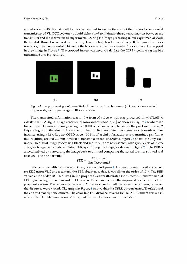
a pre-header of 40 bits using all 1 s was transmitted to ensure the start of the frames for successfultransmission of VL-OCC system, to avoid delays and to maintain the synchronization between thetransmitter and the receiver in all experiments. During the image processing in our experimental work,the two bits 0 and 1 were used, representing low and high levels, respectively. If the symbol or blockwas black, then it represented 0 bit and if the block was white it represented 1, as shown in the croppedin grey image in Figure 7. The cropped image was used to calculate the BER by comparing the bitstransmitted and bits received.
Electronics 2019, 8, x FOR PEER REVIEW 12 of 16
application. Presently, in the experimental work, the EEG signal transmitted, captured by the camera in video form, was processed offline using MATLAB to calculate BER and to determine the performance of the system and the effective link distance between the transmitter and the receiver. In order to overcome the delay, a pre-header of 40 bits using all 1s was transmitted to ensure the start of the frames for successful transmission of VL-OCC system, to avoid delays and to maintain the synchronization between the transmitter and the receiver in all experiments. During the image processing in our experimental work, the two bits 0 and 1 were used, representing low and high levels, respectively. If the symbol or block was black, then it represented 0 bit and if the block was white it represented 1, as shown in the cropped in grey image in Figure 7. The cropped image was used to calculate the BER by comparing the bits transmitted and bits received.
(a) (b) (c)
Figure 7. Image processing: (a) Transmitted information captured by camera; (b) information converted to grey scale; (c) cropped image for BER calculation.
The transmitted information was in the form of video which was processed in MATLAB to calculate BER. A digital image consisted of rows and columns [𝑟 ,𝑐 ], as shown in Figure 7a, where the transmitted bits formed an image using the OLED screen as transmitter, as per the pixel size of 32 × 32. Depending upon the size of pixels, the number of bits transmitted per frame was determined. For instance, using a 32 × 32 pixel OLED screen, 20 bits of useful information was transmitted per frame, thus requiring around 2.3 min of video to transmit a bit rate of 2.8kbps. Figure 7b shows the grey scale image. In digital image processing black and white cells are represented with grey levels of 0–255. The grey image helps in determining BER by cropping the image, as shown in Figure 7c. The BER is also calculated by converting the image back to bits and comparing the actual bits transmitted and received. The BER formula: 𝐵𝐸𝑅 = 𝐵𝑖𝑡𝑠 𝑟𝑒𝑐𝑖𝑣𝑒𝑑𝐵𝑖𝑡𝑠 𝑇𝑟𝑎𝑛𝑠𝑚𝑖𝑡𝑡𝑒𝑑
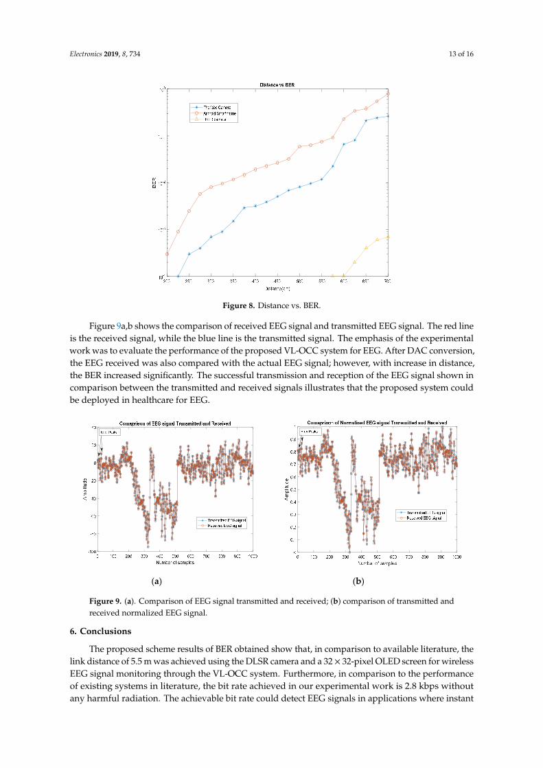
BER increases with increase in distance, as shown in Figure 8. In camera communication systems for EEG using VLC and a camera, the BER obtained to date is usually of the order of 10 . The BER values of the order 10 achieved in the proposed system illustrates the successful transmission of EEG signal using the camera and OLED screen. This demonstrates the improved performance of the proposed system. The camera frame rate of 30 fps was fixed for all the respective cameras; however, the distances were varied. The graph in Figure 8 shows that the DSLR outperformed Thorlabs and the android smartphone camera. The error-free link distance covered by the DSLR camera was 5.5 m, wherea the Thorlabs camera was 2.25 m, and the smartphone camera was 1.75 m.
Figure 7. Image processing: (a) Transmitted information captured by camera; (b) information convertedto grey scale; (c) cropped image for BER calculation.
The transmitted information was in the form of video which was processed in MATLAB tocalculate BER. A digital image consisted of rows and columns [r1,c1], as shown in Figure 7a, where thetransmitted bits formed an image using the OLED screen as transmitter, as per the pixel size of 32 × 32.Depending upon the size of pixels, the number of bits transmitted per frame was determined. Forinstance, using a 32 × 32 pixel OLED screen, 20 bits of useful information was transmitted per frame,thus requiring around 2.3 min of video to transmit a bit rate of 2.8kbps. Figure 7b shows the grey scaleimage. In digital image processing black and white cells are represented with grey levels of 0–255.The grey image helps in determining BER by cropping the image, as shown in Figure 7c. The BER isalso calculated by converting the image back to bits and comparing the actual bits transmitted andreceived. The BER formula:
BER =Bits recived
Bits TransmittedBER increases with increase in distance, as shown in Figure 8. In camera communication systems
for EEG using VLC and a camera, the BER obtained to date is usually of the order of 10−3. The BERvalues of the order 10−4 achieved in the proposed system illustrates the successful transmission ofEEG signal using the camera and OLED screen. This demonstrates the improved performance of theproposed system. The camera frame rate of 30 fps was fixed for all the respective cameras; however,the distances were varied. The graph in Figure 8 shows that the DSLR outperformed Thorlabs andthe android smartphone camera. The error-free link distance covered by the DSLR camera was 5.5 m,wherea the Thorlabs camera was 2.25 m, and the smartphone camera was 1.75 m.
Electronics 2019, 8, 734 13 of 16Electronics 2019, 8, x FOR PEER REVIEW 13 of 16
Figure 8. Distance vs. BER.
Figure 9a,b shows the comparison of received EEG signal and transmitted EEG signal. The red line is the received signal, while the blue line is the transmitted signal. The emphasis of the experimental work was to evaluate the performance of the proposed VL-OCC system for EEG. After DAC conversion, the EEG received was also compared with the actual EEG signal; however, with increase in distance, the BER increased significantly. The successful transmission and reception of the EEG signal shown in comparison between the transmitted and received signals illustrates that the proposed system could be deployed in healthcare for EEG.
(a) (b)
Figure 9. (a). Comparison of EEG signal transmitted and received; (b) comparison of transmitted and received normalized EEG signal.
6. Conclusions
The proposed scheme results of BER obtained show that, in comparison to available literature, the link distance of 5.5 m was achieved using the DLSR camera and a 32 × 32-pixel OLED screen for wireless EEG signal monitoring through the VL-OCC system. Furthermore, in comparison to the performance of existing systems in literature, the bit rate achieved in our experimental work is 2.8
Figure 8. Distance vs. BER.
Figure 9a,b shows the comparison of received EEG signal and transmitted EEG signal. The red lineis the received signal, while the blue line is the transmitted signal. The emphasis of the experimentalwork was to evaluate the performance of the proposed VL-OCC system for EEG. After DAC conversion,the EEG received was also compared with the actual EEG signal; however, with increase in distance,the BER increased significantly. The successful transmission and reception of the EEG signal shown incomparison between the transmitted and received signals illustrates that the proposed system couldbe deployed in healthcare for EEG.
Electronics 2019, 8, x FOR PEER REVIEW 13 of 16
Figure 8. Distance vs. BER.
Figure 9a,b shows the comparison of received EEG signal and transmitted EEG signal. The red line is the received signal, while the blue line is the transmitted signal. The emphasis of the experimental work was to evaluate the performance of the proposed VL-OCC system for EEG. After DAC conversion, the EEG received was also compared with the actual EEG signal; however, with increase in distance, the BER increased significantly. The successful transmission and reception of the EEG signal shown in comparison between the transmitted and received signals illustrates that the proposed system could be deployed in healthcare for EEG.
(a) (b)
Figure 9. (a). Comparison of EEG signal transmitted and received; (b) comparison of transmitted and received normalized EEG signal.
6. Conclusions
The proposed scheme results of BER obtained show that, in comparison to available literature, the link distance of 5.5 m was achieved using the DLSR camera and a 32 × 32-pixel OLED screen for wireless EEG signal monitoring through the VL-OCC system. Furthermore, in comparison to the performance of existing systems in literature, the bit rate achieved in our experimental work is 2.8
Figure 9. (a). Comparison of EEG signal transmitted and received; (b) comparison of transmitted andreceived normalized EEG signal.
6. Conclusions
The proposed scheme results of BER obtained show that, in comparison to available literature, thelink distance of 5.5 m was achieved using the DLSR camera and a 32× 32-pixel OLED screen for wirelessEEG signal monitoring through the VL-OCC system. Furthermore, in comparison to the performanceof existing systems in literature, the bit rate achieved in our experimental work is 2.8 kbps withoutany harmful radiation. The achievable bit rate could detect EEG signals in applications where instant
Electronics 2019, 8, 734 14 of 16
recording is required from a couple of seconds to a few minutes to detect brain activity. The proposedsystem has a potential crucial future impact and is investigated in order to be deployed in futurehealthcare environments due to the drawbacks of RF, especially in RF sensitive areas. Additionally,the traditional VLC systems using photodiodes as the receiver require hardware modifications andextra set up; however, deploying a camera as the receiver does not require extra modifications to theinfrastructure, due to the inbuilt filter and focusing properties of cameras, hence the proposed systemwould be beneficial in healthcare.
Author Contributions: G.A. wrote the paper, performed experiments, methodology, PCB hardware design andexperimental set up. The supervisory team, namely X.D., R.S., and R.B., supervised the work and provided thenecessary guidance and support. A.S. helped in editing the paper.
Funding: This paper is part of PhD research work of Geetika Aggarwal and she is a self-funded student.
Conflicts of Interest: The authors declare no conflicts of interest.
References
1. Nezhad, M.H.; Subari, K.S.; Yahyavi, M. Improvement of wireless transmission system performance for EEGsignals based on development of scalar quantization. J. Electr. Bioimpedance 2013, 4, 62–72.
2. Hasan, M.K.; Shahjalal, M.; Chowdhury, M.Z.; Jang, Y.M. Access point selection in hybrid OCC/RF Ehealtharchitecture for real-time remote patient monitoring. In Proceedings of the 9th International Conference onInformation and Communication Technology Convergence (ICTC 2018), Jeju Island, Korea, 17–19 October2018; pp. 716–719. [CrossRef]
3. Dhatchayeny, D.R.; Sewaiwar, A.; Tiwari, S.V.; Chung, Y.H. Experimental biomedical EEG signal transmissionusing VLC. IEEE Sens. J. 2015, 15, 5386–5387. [CrossRef]
4. Rachim, V.P.; Jiang, Y.; Lee, H.S.; Chung, W.Y. Demonstration of long-distance hazard-free wearablemonitioring system using mobile phone visible light. Opt. Express 2017, 25, 713–719. [CrossRef] [PubMed]
5. Jungnickel, V.; Uysal, M.; Ghassemlooy, Z. A European view on the next generation optical wirelesscommunication standard. In Proceedings of the 2015 IEEE Conference on Standards for Communicationsand Networking (CSCN 2015), Tokyo, Japan, 28–30 October 2015.
6. Goto, Y.; Takai, I.; Yamazato, T.; Okado, H.; Fuji, T.; Kawahito, S.; Arai, S.; Yendo, T.; Kamakura, K. A newautomotive VLC system using optical communication image sensor. IEEE Photonic J. 2016, 8, 1–17. [CrossRef]
7. Ong, Z.; Chung, W.Y. Long range VLC temperature monitoring system using CMOS of mobile camera.IEEE Sens. J. 2015, 16, 1508–1509. [CrossRef]
8. Ghassemlooy, Z.; Popoola, W.; Rajbhandari, S. Optical Wireless Communications: System and Channel Modellingwith MATLAB; CRC Press: Boca Raton, FL, USA, 2013; Volume 8, pp. 443–444.
9. Haigh, P.A.; Bausi, F.; Le Minh, H.; Papakonstantinou, I.; Popoola, W.; Burton, A.; Cacialli, F.Wavelength-multiplexed polymer LEDs: Towards 55 Mb/s organic visible light communications. IEEE J. Sel.Areas Commun. 2015, 33, 1819–1828. [CrossRef]
10. Haigh, P.A.; Ghassemlooy, Z.; Papakonstantinou, I. 1.4-Mb/s white organic LED transmission system usingdiscrete multitone modulation. IEEE Photonic Technol. Lett. 2013, 25, 615–618. [CrossRef]
11. Aoyama, H.; Oshima, M. Visible light communication using a conventional image sensor. In Proceedings ofthe IEEE 12th Annual Consumer Commununications Network Conference (CCNC 2015), Las Vegas, NV,USA, 9–12 January 2015; pp. 103–108.
12. Roberts, R.D. Space-time forward error correction for dimmable undersampled frequency shift ON-OFFkeying camera communications (CamCom). In Proceedings of the 5th International Conference Ubiquitousand Future Networks (ICUFN 2013), Da Nang, Vietnam, 2–5 July 2013; pp. 459–464.
13. Ashok, A.; Jain, S.; Gruteser, M.; Mandayam, N.; Yuan, W.; Dana, K. Capacity of pervasive camera basedcommunication under perspective distortions. In Proceedings of the 2014 IEEE International Conferenceon Pervasive Computing and Communications (PerCom 2014), Budapest, Hungary, 24–28 March 2014;pp. 112–120.
14. Takai, I.; Harada, T.; Andoh, M.; Yasutomi, K.; Kagawa, K.; Kawahito, S. Optical vehicle-to-vehiclecommunication system using LED transmitter and camera receiver. IEEE Photonic J. 2014, 6, 1–14. [CrossRef]
Electronics 2019, 8, 734 15 of 16
15. Chow, C.W.; Chen, C.Y.; Chen, S.H. Enhancement of signal performance in LED visible light communicationsusing mobile phone camera. IEEE Photonic J. 2015, 7, 7903607. [CrossRef]
16. Cao, Y.; Song, H.; Kaiwartya, O.; Zhou, B.; Zhuang, Y.; Cao, Y.; Zhang, X. Mobile edge computing forbig-data-enabled electric vehicle charging. IEEE Commun. Mag. 2018, 56, 150–156. [CrossRef]
17. Prasad, M.; Liu, Y.T.; Li, D.L.; Lin, C.T.; Shah, R.R.; Kaiwartya, O.P. A new mechanism for data visualizationwith TSK-type preprocessed collaborative fuzzy rule based system. J. Artif. Intell. Soft Comput. Res. 2017, 7,33–46. [CrossRef]
18. Cao, Y.; Kaiwartya, O.; Wang, R.; Jiang, T.; Cao, Y.; Aslam, N.; Sexton, G. Toward efficient, scalable, andcoordinated on-the-move EV charging management. IEEE Wirel. Commun. 2017, 24, 66–73. [CrossRef]
19. Aliyu, A.; Abdullah, A.H.; Kaiwartya, O.; Cao, Y.; Lloret, J.; Aslam, N.; Joda, U.M. Towards video streamingin IoT Environments: Vehicular communication perspective. Comput. Commun. 2018, 118, 93–119. [CrossRef]
20. Khasawneh, A.; Latiff, M.S.B.A.; Kaiwartya, O.; Chizari, H. A reliable energy-efficient pressure-based routingprotocol for underwater wireless sensor network. Wirel. Netw. 2018, 24, 2061–2075. [CrossRef]
21. Kaiwartya, O.; Abdullah, A.H.; Cao, Y.; Lloret, J.; Kumar, S.; Shah, R.R.; Prasad, M.; Prakash, S. Virtualizationin wireless sensor networks: Fault tolerant embedding for internet of things. IEEE Internet Things J. 2018, 5,571–580. [CrossRef]
22. Farhan, L.; Kharel, R.; Kaiwartya, O.; Hammoudeh, M.; Adebisi, B. Towards green computing for Internetof things: Energy oriented path and message scheduling approach. Sustain. Cities Soc. 2018, 38, 195–204.[CrossRef]
23. Chatterjee, S.; Miller, A. Biomedical Instrumentation Systems; Delmar CENGAGE Learning: Clifton Park, NY,USA, 2010.
24. Luan, B.; Jia, W.; Thirumala, P.D.; Balzer, J.; Gao, D.; Sun, M. A feasibility study on a single-unit wireless EEGsensor. In Proceedings of the 12th International Conference on Signal Processing (ICSP 2014), Hangzhou,China, 19–23 October 2014; pp. 2282–2285.
25. Lin, C.-H.; Chuang, C.-H.; Huang, C.-H.; Tsai, S.-F.; Lu, S.-W.; Chen, T.-H.; Ko, L.-W. Wireless and wearableEEG system for evaluating driver vigilance. IEEE Trans. Biomed. Circuits Syst. 2014, 8, 165–176.
26. Lee, S.M.; Kim, J.H.; Park, C.; Hwang, J.; Hong, J.S.; Lee, K.H.; Lee, S.H. Self-adhesive and capacitivecarbon nanotube-based electrode to record electroencephalograph signals from the hairy scalp. IEEE Trans.Biomed. Eng. 2016, 63, 138–147. [CrossRef]
27. Huang, Y.-J.; Wu, C.-Y.; Wong, A.M.-K.; Lin, B.-S. Novel active comb-shaped dry electrode for EEGmeasurement in hairy site. IEEE Trans. Biomed. Eng. 2015, 62, 256–263. [CrossRef]
28. Yu, Y.-H.; Lu, S.-W.; Chuang, C.-H.; King, J.-T.; Chang, C.-L.; Chen, S.; Chen, S.-F.; Lin, C.-T. An inflatable andwearable wireless system for making 32-channel electroencephalogram measurements. IEEE Trans. NeuralSyst. Rehab. Eng. 2016, 24, 806–813. [CrossRef]
29. Goverdovsky, V.; Looney, D.; Kidmose, P.; Mandic, D.P. In-ear EEG from viscoelastic generic earpieces:Robust and unobtrusive 24/7 monitoring. IEEE Sens. J. 2016, 16, 271–277. [CrossRef]
30. Xu, R.; Jiang, N.; Dosen, S.; Lin, C.; Mrachacz-Kersting, N.; Dremstrup, K.; Farina, D. Endogenous sensorydiscrimination and selection by a fast brain switch for a high transfer rate brain-computer interface. IEEE Trans.Neural Syst. Rehab. Eng. 2016, 24, 901–910. [CrossRef] [PubMed]
31. Mihajlovic, V.; Grundlehner, B.; Vullers, R.; Penders, J. 1.4-Mb/s white organic LED transmission systemusing discrete multitone modulation; Wearable, Wireless EEg solutions in Daily Life Applications: What weare missing? IEEE J. Biomed. Health Inform. 2015, 25, 615–618.
32. NeuroSky. Available online: http://www.neurosky.com (accessed on 27 April 2019).33. Emotiv. Available online: http://emotiv.com (accessed on 27 April 2019).34. G.Nautillus. Available online: http://www.gtec.at/Products/Hardware-and-Accessories/g.Nautilus-Specs-
Features (accessed on 27 April 2019).35. Mindo. Available online: http://mindo.com.tw/en/goods.php?act=view&no=4 (accessed on 27 April 2019).36. Cognionics. Available online: http://www.cognionics.com/index.php/products/hd-eeg-systems/quick-20-
dry-headset (accessed on 27 April 2019).37. Enobio. Available online: http://www.neuroelectrics.com/products/enobio/ (accessed on 27 April 2019).38. Ng, X.-W.; Chung, W.-Y. VLC-based medical healthcare information system. Biomed. Eng. Appl. Basis Commun.
2012, 24, 155–163. [CrossRef]
Electronics 2019, 8, 734 16 of 16
39. Zhang, Q.; Wang, P.; Liu, Y.; Peng, B.; Zhou, Y.; Zhou, Z.; Dai, Y. A real-time wireless wearableelectroencephalography system based on Support Vector Machine for encephalopathy daily monitoring.Int. J. Distrib. Sens. Netw 2018. [CrossRef]
40. Aggarwal, G.; Dai, X.; Binns, R.; Saatchi, R.; Busawon, K.; Bentley, E. Wireless EEG signal transmission usingvisible light optical camera communication. In Applications of Computing and Communication Technologies;Deka, G., Kaiwartya, O., Vashisth, P., Rathee, P., Eds.; Springer: Singapore, 2018; Volume 899, pp. 152–161.
41. Vu, T.L.; Nguyen, T.; Kim, C.S.; Sin, E.B.; Jeong, J.; Jang, Y.M. Survey of indoor optical camera communication(OCC) systems for the Internet of lights. In Proceedings of the 2017 International Conference on Informationand Communication Technology Convergence (ICTC 2017), Jeju Island, Korea, 18–20 October 2017;pp. 700–703. [CrossRef]
42. Islam, A.; Hossan, M.T.; Jang, Y.M. Convolutional neural network scheme–based optical cameracommunication system for intelligent Internet of vehicles. Int. J. Distrib. Sens. Netw. 2018, 14. [CrossRef]
43. Teli, S.; Chung, Y. Selective capture based high-speed optical vehicular signaling system. Signal Process.Image Commun. 2018, 68, 241–248. [CrossRef]
44. Ifthekhar, M.S.; Hossain, M.A.; Hong, C.H.; Jang, Y.M. Radiometric and geometric camera model for opticalcamera communications. In Proceedings of the 2015 Seventh International Conference on Ubiquitous andFuture Networks, Sapporo, Japan, 7–10 July 2015; pp. 53–57. [CrossRef]
45. Yamazato, T.; Kinoshita, M.; Arai, S.; Souke, E.; Yendo, T.; Fujii, T.; Kamakura, K.; Okada, H. Vehiclemotion and pixel illumination modeling for image sensor based visible light communication. IEEE J. Sel.Areas Commun. 2015, 33, 1793–1805. [CrossRef]
46. Wu, S.; Wang, H.; Youn, C.-H. Visible light communications for 5Gwireless networking systems: From fixedto mobile communications. IEEE Netw. 2014, 28, 41–45. [CrossRef]
47. Iizuka, N. OCC Proposal of Scope of Standardization and Applications. IEEE 802.15 SG7a Standardization Documents;IEEE: Piscataway, NJ, USA, 2014.
48. Shahjalal, M.; Hossan, M.T.; Hasan, M.K.; Chowdhury, M.Z.; Le, N.T.; Jang, Y.M. An implementationapproach and performance analysis of image sensor based multilateral indoor localization and navigationsystem. Wirel. Commun. Mob. Comput. 2018, 2018, 7680780. [CrossRef]
49. Deguchi, J.; Yamagishi, T.; Majima, H. A 1.4Mpixel CMOS image sensor with multiple row-rescan based datasampling for optical camera communication. In Proceedings of the Asian Solid-State Circuits Conference(A-SSCC 2014), KaoHsiung, Taiwan, 10–12 November 2014.
50. Zaman, M.; Hossan, T.; Islam, A.; Jang, J.M. A Compartive Survey of Optical Wireless technolgies: Architecturesand Applications; IEEE: Piscataway, NJ, USA, 2018; Volume 6.
51. Etoolbox. Bioelectromagnetism MATLAB Toolbox. Available online: http://eeg.sourceforge.net (accessed on8 January 2019).
52. DD-160128FC-1A DENSITRON, Graphic OLED, 160 × 128, RGB, 2.8 V, Parallel, Serial, 35.8 mm × 30.8 mm,−20 ◦C | Farnell UK. Available online: https://uk.farnell.com/densitron/dd-160128fc-1a/display-oled-rgb-160x128/dp/1498857 (accessed on 27 April 2019).
© 2019 by the authors. Licensee MDPI, Basel, Switzerland. This article is an open accessarticle distributed under the terms and conditions of the Creative Commons Attribution(CC BY) license (http://creativecommons.org/licenses/by/4.0/).