Embed Size (px)
Citation preview
1
Experimental Cloud-based Ray Tracing Using Intel® MIC Architecture for Highly Parallel Visual Processing
Introduction
A game-changing factor in computing is the rise of the cloud. While the word sometimes seems to be
overused, the concept offers interesting benefits for both companies and end-users. One example of
taking advantage of the cloud is related to computer games. Companies like OnLive* and Gaikai* are
making a business out of offering a service in which the game itself runs on servers in the cloud. It
processes user interactions from the game client, and the server sends back a compressed, rendered
image of the game to the user.
There are many advantages of a cloud-based rendering approach. For instance, the user doesn’t need to
wait for the installation of the game and doesn’t need to worry about patching the game to the latest
state. The amount of used hard disk space on the user’s machine is much lower. As the game can’t be
copied from the client side, there is no need for anti-piracy checks like putting the game DVD into your
machine. For developers it also enables an easy way to release a demo version of the game, such as by
providing a limited access time window to the full game so people can get a first impression of it.
Another advantage is that a game client could run on many different operating systems and might
therefore save the amount of work that is sometimes used to port a game across different platforms.
More platforms, such as netbooks, tablets, and smartphones, could run high-end games since intensive
calculations are done on the server. This also opens the door to running high-end, even professional
graphical capabilities on lightweight consumer devices. Current games are usually limited to using the
hardware rasterizer that is on common graphics cards in order to achieve the required performance that
gamers expect. While this approach has advantages, it also limits the choices a game developer could
use for their game. There might be other rendering algorithms, like point rendering, voxel rendering, or
ray tracing, that could enable games to look much more realistic.
Ray tracing is a rendering technique that uses the laws of physics to create more photorealistic graphics
by accurately calculating effects like reflections, refractions, and shadows. However, the computational
requirements of ray tracing limit its use for interactive consumer applications like games. The cloud
gaming model provides one method to give more people access to the high-end hardware needed to
perform the ray tracing in real-time.
In recent years, Intel Labs has shown steady progress towards developing real-time ray tracing engines
running on multicore Intel® processor-based platforms. In 2008, we were able to show Quake Wars: Ray
Traced running at 15-20 frames per second (fps) on an Intel® Xeon® processor-based server using four
quad-core CPUs. After several months of making optimizations, we showed the demo using the same
four socket server, but with the newly updated six-core Intel® Xeon® X7460 processors at 20-35 fps. The
following year the next Intel processor allowed us to go down from a server to a workstation system

2
with two sockets achieving the same frame. It is clear that we will see continued performance increases
with higher core counts and new architectures like Intel® microarchitecture code name Sandy Bridge.
One specifically interesting platform for this algorithm is the upcoming Intel® Many Integrated Core
Architecture (Intel® MIC Architecture) announced in May 2010. As ray tracing is a highly parallel
algorithm, Intel MIC Architecture will help provide big gains in performance by increasing the number of
available cores for highly parallel applications in the high performance computing (HPC) market and for
datacenters. This leads us to the topic of this paper: bringing together the Intel MIC Architecture along
with a cloud-based gaming model to enable more advanced and realistic image rendering with real-time
ray tracing.
Ray Tracing Overview
Ray tracing is a rendering algorithm that simulates light rays found in nature, with one slight difference.
In nature, the rays originate from a light source (e.g. the sun) and eventually hit the human eye. The ray
tracing algorithm traces this process in reverse: from the eye (as a virtual camera) into the scene. The
points where these rays hit geometric objects are calculated. Then, a shader program is called for the
surfaces that got hit.
A ray from the virtual camera hits the car and gets reflected toward the house. A shadow ray is shot from
the hit position at the car toward the light source.
Through this process, material properties such as reflectivity and transparency are evaluated. Colors
from textures can be added, and secondary rays that test for lighting, reflection, and refraction can be
traced from here.

3
Ray tracing is already heavily used in the professional graphics market. This usually is done for offline
(i.e., non-interactive) tasks where a significant amount of time is spent on a single image. In order to
enable some degree of interactivity, there are often previews of the final image that get refined over
time. In some cases, large clusters have been the solution to gain interactivity.
The automotive industry is an important example of the professional use of ray tracing. Before a car gets
built, it is valuable to be able to preview it first in a photorealistic way. Through this process, the
manufacturer is able to accurately model the car to the desired properties and is able to detect flaws in
the design easily—for instance, if a certain object or shape in the car would cause reflections that might
irritate the driver. For modeling an object like a headlight, complex global illumination calculations
where multiple rays bounce inside the object have to be solved. Ray tracing has proven to be the best
solution for getting those physically correct images.
Offline-rendered headlight model of a car
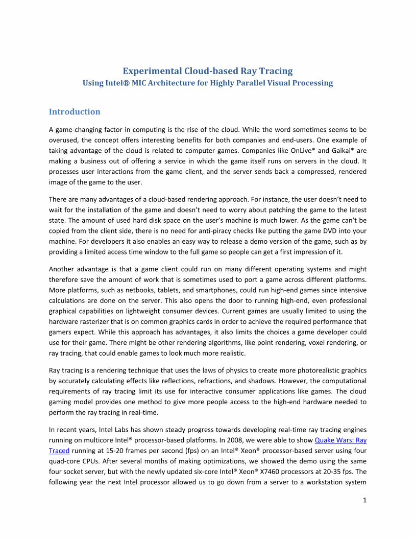
Another application of ray tracing is in the area of medical visualization. Scanning devices used for
computed tomography (CT) or magnetic resonance tomography (MRT) create 3D data of an object like
the human brain or a skull. That volumetric information has to be displayed on a computer screen.
While there are many different methods to do this, ray tracing is the most accurate one.
4
Volumetric data of a skull visualized using rays
(Source: http://en.wikipedia.org/wiki/File:High_Definition_Volume_Rendering.JPG)
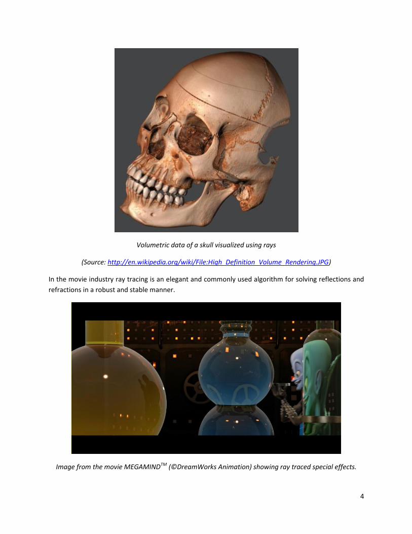
In the movie industry ray tracing is an elegant and commonly used algorithm for solving reflections and
refractions in a robust and stable manner.
Image from the movie MEGAMINDTM (©DreamWorks Animation) showing ray traced special effects.

5
Intel® MIC Architecture Ray Tracing The demonstration described below is an evaluation of the combination of a cloud-based gaming
approach and utilizing ray tracing for rendering using Intel MIC Architecture.
Hardware Setup
For this project four “server” machines have been used to represent the cloud. The relevant
components of each machine are:
Motherboard: Intel® DX58SO (code name Smackover)
CPU: Intel® Core™ i7-980x processor (6 cores, 2 threads per core, 3.33 GHz)
Intel code name Knights Ferry PCIe card (32 cores, 4 threads per core)
Gigabit Ethernet
Intel code name Knights Ferry is the first-generation development platform for the Intel MIC
Architecture. It includes a PCIe card that has a 32-core chip on it that is clocked at 1.2 GHz. The
development platform is programmable with the regular tools and programming languages that
developers regularly use. A bit further out there are plans for an Intel MIC Architecture-based
product, code named Knights Corner, that will use 22nm manufacturing technology and will
therefore be able to even have more than 50 cores on the chip.
As a thin client (representing the gamer’s machine), a small laptop was chosen. The properties are:
CPU: Intel® Core™2 Duo processor P9600 (2 cores, 2.66 GHz)
13-inch screen at 1280x800
Gigabit Ethernet
Software Setup
Game content was taken from the German version of the game Wolfenstein* (2009), provided by id
Software* and Raven Software*.
The ray tracing was performed by an experimental engine developed by Intel Labs. It is programmable
over a clearly defined API in order to pass in geometry, camera data, textures, changed states, etc.
Additionally, an HLSL-like shading language is supported to write high-performance shading code in a
convenient way.
The ray tracing engine has two parts. One runs completely on the CPU and is used to communicate with
the Knights Ferry card in order to upload the content, manage states, and send rendering commands.
The other part is executed on Intel MIC Architecture. It has been implemented in a very similar manner
to a regular Intel® architecture CPU in C++, with special code to utilize the 16-wide SIMD units. The
renderer uses 31 of 32 cores – the last one is left free so it can handle whatever workload the driver
requires. Given that each core has four threads, this means there are 124 threads available. These are
dynamically allocated on Knights Ferry to different tasks, the biggest one being the actual rendering task
that traces rays and colors pixels. The second most intense one is used to update internal acceleration
6
structures. Those are holding representations of the game’s geometry (triangles) in a way that makes it
faster for rays to find the potential intersecting geometry. Dynamic changes of the scene (movement of
players, particle updates, etc.) require that those acceleration structures are updated as well with this
new information.
Client-Server Rendering
The Intel® Core™ i7 processor on the server runs a game engine that processes and updates all states
(e.g., position of the players, which weapon is currently chosen, etc.) and communicates those to the ray
tracing engine that is running as described above with an interface on the CPU and for rendering on
Knights Ferry. It also transfers rendered pixels over TCP/IP to the client.
The client processes the user interface (key presses, mouse movements) and evaluates their actions (for
example, pressing the Up key will make the player move forward). Updated game states are sent to the
servers. The client receives pixel data from the server and displays it on the screen.
In order to combine the calculation power of multiple hardware units, in this case the four servers, there
are different methods that can be used. Here are two of them in more detail:
Distributing tile-based rendering across all servers. This method splits the task of rendering a
ray-traced image into small tiles (like 32x32 or 64x64 pixels) and assigns them to a specific
server. The benefit of this approach is that it has very low latency. The machines will work
together to finish this one frame as fast as possible. The drawback is that a smart algorithm is
required for accurate load balancing between the servers. Some tiles might be calculated much
faster than others (e.g., displaying the sky without any geometry is very fast). Therefore it could
happen that all but one of the machines are already done with their work but have to sit idle
until the last one is finished. To solve that, there are approaches like task stealing, where an idle
thread can grab work from the pipeline of another busy thread, that should perform well.
Alternate frame rendering. Using this approach, a specific frame is assigned to a specific
machine. The benefit is that this is easy to assign to each server. In most cases there is not a
significant difference in the time to calculate succeeding frames; therefore the work is balanced
nicely. The drawback is that this method introduces additional lag. In the case of four servers,
this adds a three-frame delay to what is displayed on the client’s machine. At a frame rate of 60
Hz, the delay would be 50 milliseconds (ms). Using double buffering as in our demo setup, this
leads to a seven-frame delay (117 ms).
Given the amount of additional latency through the second method, it is recommended for a
commercial implementation to use the tile-based approach. Nevertheless, for the purpose of this
research study, our first implementation used alternate frame rendering with the option to improve
using the tile-based method in a future revision.
Compression
7
In order to upload an image from memory to the graphical device that shows it on a screen, almost all
modern devices require an image with red, green, blue, and alpha (RGBA) channels, each of them having
8 bits of information. At a target resolution of 1280x720, a single image with this information takes 3600
KB of memory. As the alpha channel doesn’t contribute any useful information, this can be easily
reduced to 2700 KB. At 60 Hz this transfer would require a data rate of around 158.2 MB (1264 Mbit)
per second, and therefore exceeds even the bandwidth of Gigabit Ethernet. Obviously some form of
compression needs to be used to better handle the amount of data.
Using compression introduces additional calculations on the server side for encoding and on the client
side for decoding. On the servers there are plenty of resources to do compression. In this setup, an
otherwise almost idle 6-core Intel® Core™ i7 processor performs a multi-threaded encoding algorithm.
Alternatively, the compression could have also been done directly on the Knights Ferry card. The client,
on the other hand, might be a lightweight system and require quite some time to decode the image
before being able to display it.
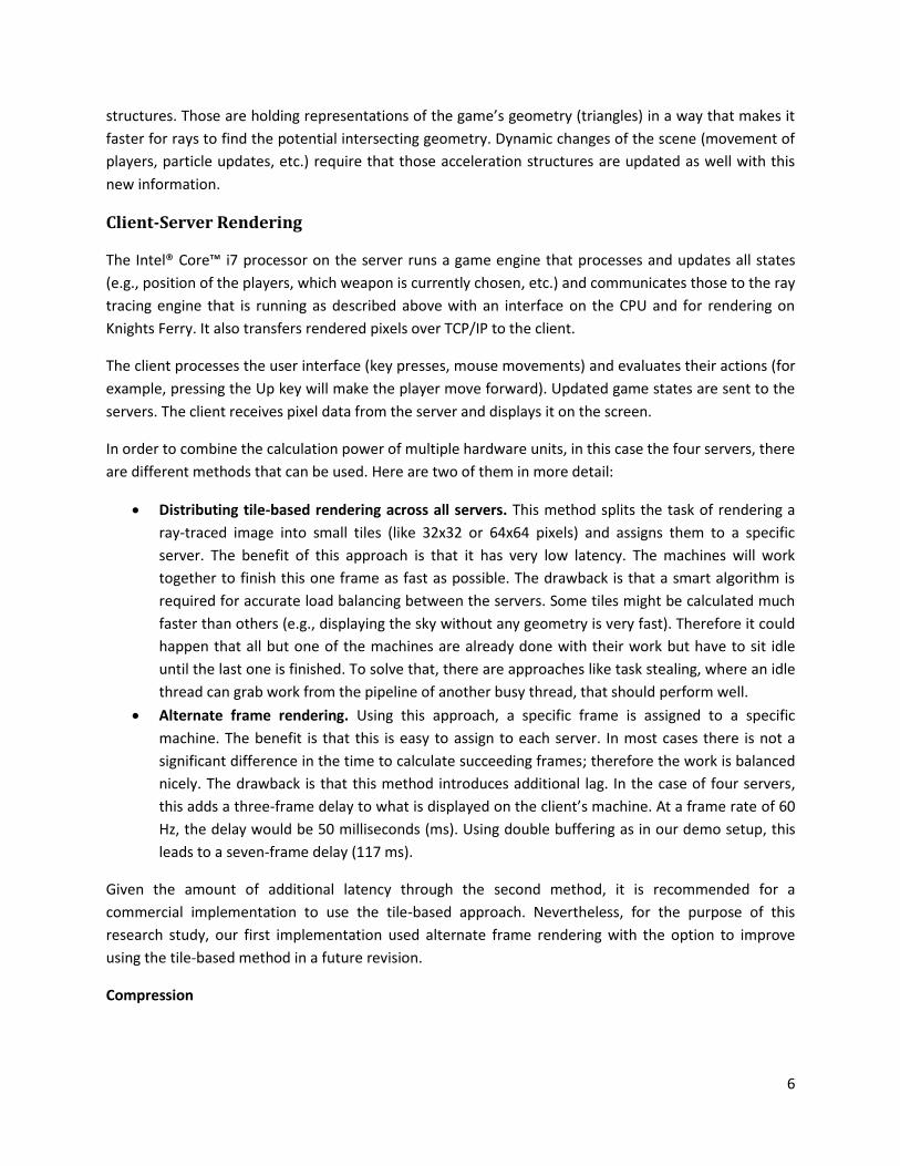
There are multiple possible coder-decoders (codecs) that can be used. OnLive* has indicated that they
use a special encoding chip to create a propriety video stream using their own codec. Gaikai* is using
the H.264 compression codec that can also be found in YouTube* and Blu-ray* videos. Using about 5
Mbit/s for a video stream at 1280x720 gives reasonable quality, but also leaves room for improvement.
If more bandwidth should be available, most codecs can utilize them easily by just changing a few
parameters in order to achieve higher image quality.
Screenshot from Dirt 2* using OnLive*.
8
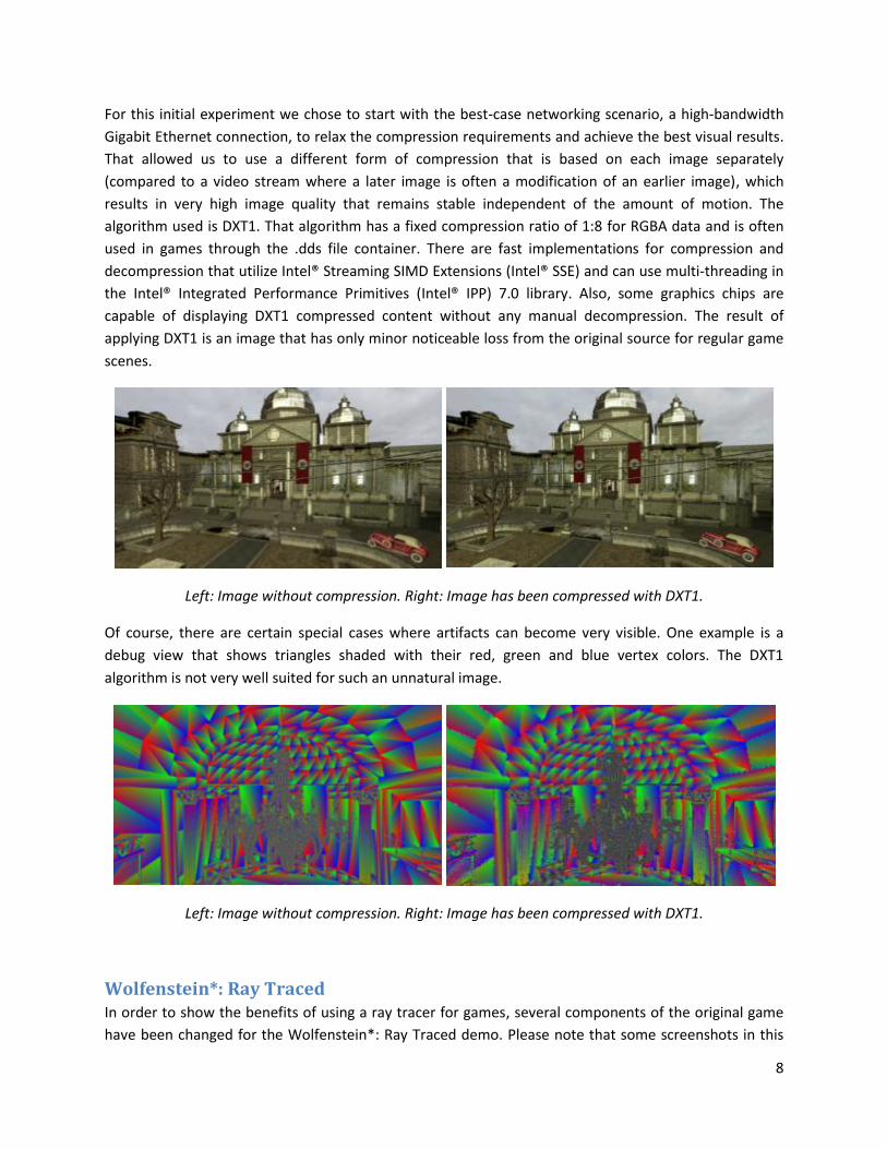
For this initial experiment we chose to start with the best-case networking scenario, a high-bandwidth
Gigabit Ethernet connection, to relax the compression requirements and achieve the best visual results.
That allowed us to use a different form of compression that is based on each image separately
(compared to a video stream where a later image is often a modification of an earlier image), which
results in very high image quality that remains stable independent of the amount of motion. The
algorithm used is DXT1. That algorithm has a fixed compression ratio of 1:8 for RGBA data and is often
used in games through the .dds file container. There are fast implementations for compression and
decompression that utilize Intel® Streaming SIMD Extensions (Intel® SSE) and can use multi-threading in
the Intel® Integrated Performance Primitives (Intel® IPP) 7.0 library. Also, some graphics chips are
capable of displaying DXT1 compressed content without any manual decompression. The result of
applying DXT1 is an image that has only minor noticeable loss from the original source for regular game
scenes.
Left: Image without compression. Right: Image has been compressed with DXT1.
Of course, there are certain special cases where artifacts can become very visible. One example is a
debug view that shows triangles shaded with their red, green and blue vertex colors. The DXT1
algorithm is not very well suited for such an unnatural image.
Left: Image without compression. Right: Image has been compressed with DXT1.
Wolfenstein*: Ray Traced In order to show the benefits of using a ray tracer for games, several components of the original game
have been changed for the Wolfenstein*: Ray Traced demo. Please note that some screenshots in this

9
section have been rendered with supersampling. Measurements and images without this will be given in
a later section.
Geometry
Ray tracing engines typically use acceleration structures, a hierarchy placed over the geometry that
organizes the scene to allow a ray’s interactions with objects to be calculated more efficiently. This leads
to the nice property that for static content, the amount of required calculations for a ray only increases
logarithmically with the number of triangles. Therefore, higher geometric detail can be used with only a
small impact on the performance.
The complete Wolfenstein* game level used for the demonstration consisted about around 300,000
triangles in the original form. To showcase the ability to have more geometry available, two objects
were changed to use extreme high polygonal details. The first was the chandelier model, made out of
around 1,000,000 triangles. The second was a detailed car model with roughly 300,000 triangles.
Left: Old chandelier model. Right: New, highly detailed chandelier model
The performance impact of changing these models and rendering them with the triangle debug shader
was only 15-20% percent. Looking at the content generation pipeline, this means that such high-
resolution models can just be taken out of the 3D modeling software and can be used in the game
directly without the need for artists to painfully reduce every possible triangle, and without the need to
use tricks like normal maps to fake the detailed geometry.
Shading
Through the ability to trace arbitrary rays on demand, ray tracing allows interesting effects for shading.
10
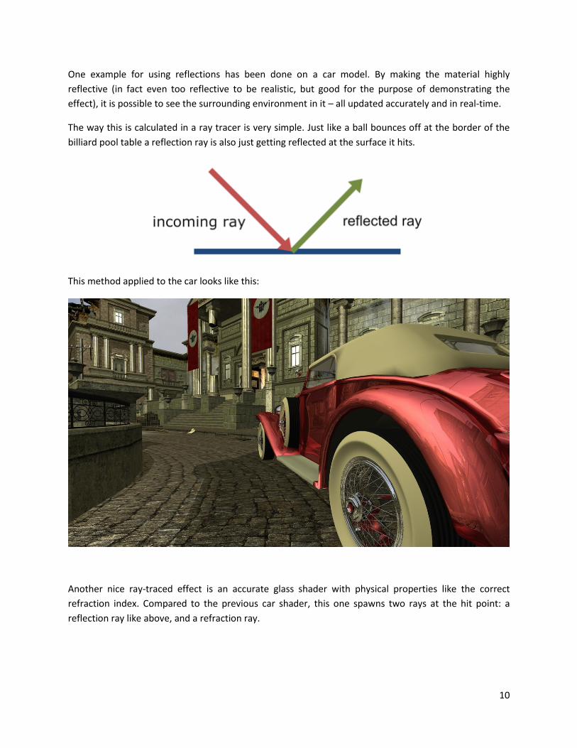
One example for using reflections has been done on a car model. By making the material highly
reflective (in fact even too reflective to be realistic, but good for the purpose of demonstrating the
effect), it is possible to see the surrounding environment in it – all updated accurately and in real-time.
The way this is calculated in a ray tracer is very simple. Just like a ball bounces off at the border of the
billiard pool table a reflection ray is also just getting reflected at the surface it hits.
This method applied to the car looks like this:
Another nice ray-traced effect is an accurate glass shader with physical properties like the correct
refraction index. Compared to the previous car shader, this one spawns two rays at the hit point: a
reflection ray like above, and a refraction ray.

11
This shader used on the chandelier model looks like this:
Distortions of the background by looking through a ray traced glass shader.
12
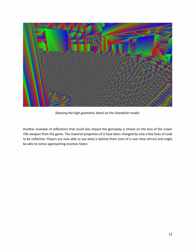
Showing the high geometric detail on the chandelier model.
Another example of reflections that could also impact the gameplay is shown on the lens of the sniper
rifle weapon from the game. The material properties of it have been changed by only a few lines of code
to be reflective. Players are now able to see what is behind them (sort of a rear-view mirror) and might
be able to notice approaching enemies faster.

13
Reflective scope gives players information about what is happening behind them.
Another interesting effect added is the surveillance station. Games already do this sort of thing, but in a
limited way. Sometimes there is a room with a screen in it that shows a different part of the scene. In
some games, there is a button to change what areas the screen displays. New here is the possibility to
have many different screens at the same time while still staying at a good performance level.
Left: Surveillance station showing 12 different parts of the level. Right: Recursion effects are also easily
done.
The way it works is simple. Each screen has exactly one offset and one viewing direction defined. If a ray
hits that screen, the offset is added to that position. From that, another ray in the specific direction
which was defined earlier will be traced. That will hit another surface which will return a color. This
effect is related to the camera portal effects (previously demonstrated in the earlier Quake Wars*: Ray
Traced project, but differs in that on the TV screens, the displayed picture remains the same
independent of the player’s view angle, while for portals, the player can get other information by
14
looking from the side of a portal instead of looking into it from the front. That is because in portal
effects, the incoming viewing direction of each ray is taken into account, compared to the fixed direction
that the TV screen has.
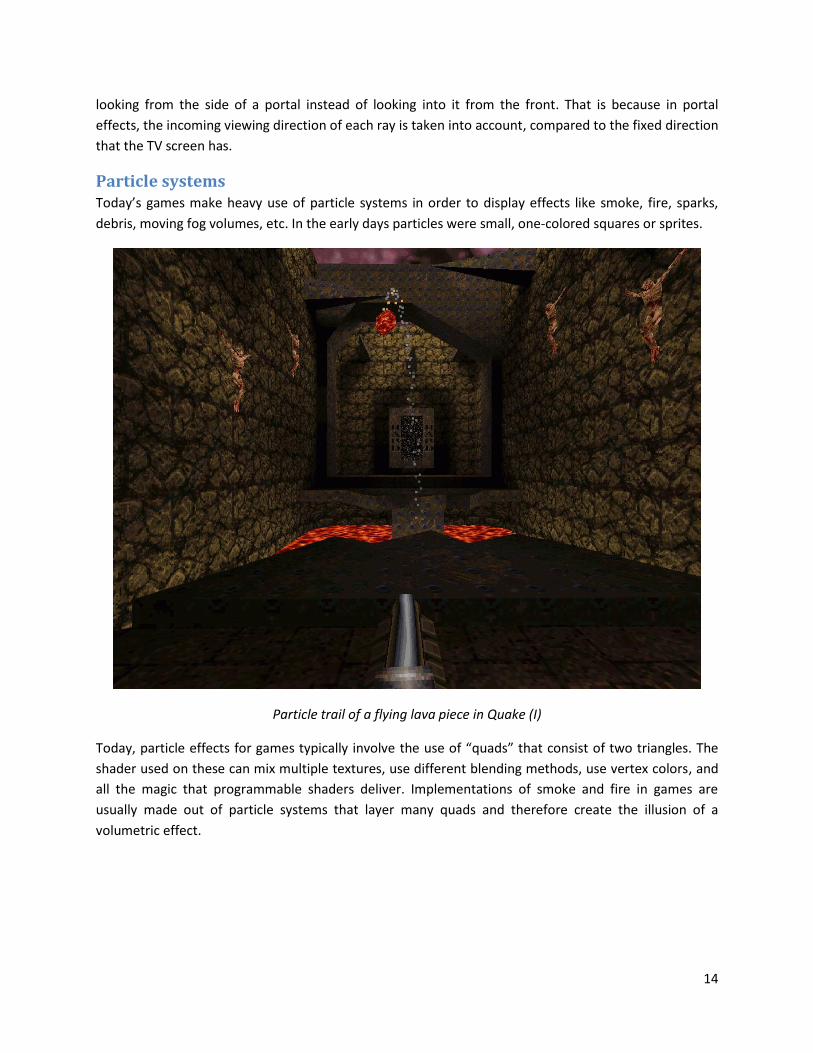
Particle systems Today’s games make heavy use of particle systems in order to display effects like smoke, fire, sparks,
debris, moving fog volumes, etc. In the early days particles were small, one-colored squares or sprites.
Particle trail of a flying lava piece in Quake (I)
Today, particle effects for games typically involve the use of “quads” that consist of two triangles. The
shader used on these can mix multiple textures, use different blending methods, use vertex colors, and
all the magic that programmable shaders deliver. Implementations of smoke and fire in games are
usually made out of particle systems that layer many quads and therefore create the illusion of a
volumetric effect.

15
Smoke and fire implementation using particles. Left: Shaded view. Right: Triangle debug view.
Usually those many layers of particles are aligned towards the eyes of the player. For debugging
purposes this setup can be frozen, and a look at it from the side reveals more details about the amount
of layering.
Debug view from the side of a frozen particle view. Left: Shaded view. Right: Triangle debug view.
This approximation of using layers has been developed specifically for games using rasterization, as it
can be calculated in a fast way with this algorithm. We implemented the same in this demo, but
recommend that for ray-traced games, another algorithm to display volumes should be used.
In order for the ray tracer to display those layered effects correctly, the ray has to hit the first surface.
The shader program returns a color value after a texture lookup and defines some amount of
transparency. From here on, the ray has to continue until it hits the next surface to repeat this step. In
our tests, we required in the hardest cases a recursion depth of 50 to guarantee the correct display. This
can obviously become very performance-intensive, and in fact rendering those particles in the
rasterization-optimized way using a ray tracer is the most expensive visual effect in the demo.

16
Debug view shows performance hot spots when rendering particles. Bright means more intensive than
dark.
Given the restriction that all those surfaces are quads and face the same direction, there are some
optimizations that could be applied when rendering this. Also, different and potentially faster rendering
methods where such a particle effect is calculated could be used and afterwards blended into the image.
The way it is likely this technology will evolve in the future is to have real volumetric data instead of
trying to simulate the effect of it through layering. For example, smoke would naturally distribute in the
air and change according to obstacles. Using ray tracing, the brightness values inside the smoke cloud
could be adapted to the environment.

17
Offline simulated smoke using FumeFX*. Author: Sam Khorshid
Video: http://www.afterworks.com/FumeFX/anims/SmokeCollection.wmv
Performance Here are some example scenes and how they perform in the cloud-based setup.
78 fps 53 fps
66 fps 70 fps
62 fps 38 fps

18
Latency Two commonly used terms in networking are bandwidth and latency:
Bandwidth: The amount of data that can be transported over the network from a certain source to a
certain destination in a given time. This can be, for example, 12 Mbits per second which is sometimes
found in home Internet connections, or 1000 Mbits per second for Gigabit Ethernet. It is often compared
with a highway and how many lanes there are: Even if there were a highway with 1000 lanes between
San Francisco and Los Angeles, a single car could still not drive the distance 1000 times faster.
Network latency: Describes the delay from sending a network packet from a source to the destination.
Latency has a high impact on the cloud-based gaming experience. The latency of a packet from one
machine to another machine and back can be tested using the ping command.
Assuming the available bandwidth is not limiting, then the latency comes from the physical limitation of
the speed of light, and also delays from various hops that a network packet goes through from one
physical connection to another (through routers, switches, etc.), and through the layers it has to pass to
get to the operating system and finally the application.
Bandwidth will influence the quality of the image that the player receives in a cloud-based setup.
Internet connection bandwidth has been increasing over the last years and can be expected to continue
increasing.
The (total) latency will impact how long it takes from, for example, moving the mouse locally to seeing
that update on the screen. The first thought might be that this is only dependent on the network
latency, but there are many other contributing factors that in some cases can be adjusted to deliver a
better gaming experience. In the following steps, which describe the process from the input controller
to the update on the screen, the assumption of a target frame rate of 60 Hz will be made. This means
each frame takes 16. 6 ms, though for simplicity this will be rounded to 17 ms. A network latency of 80
ms for a round trip (40 ms one way) will be assumed.

19
The process from the input controllers to the update it causes on the monitor
Step 1 (input controllers): In the latest operating systems from Microsoft*, devices that are
connected over USB are in default mode polled at 125 Hz. Therefore, in the worst case, 8 ms latency
could come from this. There are some techniques and some vendor-specific mouse drivers that can
change this rate to, for example, 1000 Hz. Often wireless keyboards and mice have even higher latencies
and should therefore be avoided to reduce lag.
Step 2: After the movement through the input controller has been processed, it might take a short
time until the game client reaches the piece of code that evaluates those movements. For example, the
client might be currently busy with other calculations (in a single threaded game client version, this
could be due to receiving the last rendered frame or uploading it to the graphics card). The maximal
latency would be almost one frame (17 ms). By using multiple threads in the game client, this lag could
be reduced, but might require additional synchronization about when an update should be sent out to
the servers.
Step 3: Having evaluated all movements, a network packet with data such as the updated player
position will be sent to the server and requires 40 ms. Generally, to lower network latency, it helps to
have the servers close enough to be reached with a small number of hops. Some routers have special
optimizations to prioritize network packets for online gaming, which might help for the first hop from
the client’s device to the Internet-connected router.
Step 4: Now the server has received the updated information. Assuming it is done rendering the
previous frame, the new data can be used. But games often use a method where multiple frames are
rendered in flight. The benefit is that this leads to higher and smoother average performance, because
the calculations for rendering and scene updates never run dry as there is always more work available.
Common default settings in graphics drivers allow pre-rendering of up to 3 frames.
Unless this value is lowered, this potentially adds 50 ms of latency. In a setup with multiple machines
that are each rendering individual frames, there is additional latency. As mentioned earlier, a tile-based
approach should be used to avoid this overhead. Once a frame is rendered, it has to be brought into
main memory. The image could have been either compressed directly on the device that rendered it, or
it could be compressed later by the CPU. As the server usually is very powerful, the compression
consumes only a small fraction of time (around 2 ms for DXT1 in 1280x720).
Step 5: The compressed frame is sent to the client, which consumes 40 ms.
Step 6: Back at the client, the compressed frame needs to be displayed. Either there could be a way
to upload the compressed image directly onto the graphics card (e.g., through support for DXT1
textures), or it has to be decompressed manually. As the client does usually not have a lot of
horsepower, this step could be delayed by one frame: while the client already receives the next frame
over the network, it could finish off decompressing the old one. This adds another 17 ms of latency, but
might be required as an optimization for small devices. Uploading the color data from the client’s main
memory to the graphics card that displays the image will also take some time. It might be required to do
this asynchronously and live with another 17ms of latency. Also, in case the pictures should be uploaded
20
into a texture and then displayed as a quad on the full screen over Microsoft DirectX*, for example, it
should be made certain that the graphics card settings at the client for the maximal amount of pre-
rendered frames don’t add any extra delays.
Step 7: Lastly, the outgoing picture from the graphics card has to be displayed on a screen. Besides the
limitation that currently most flat screen monitors can only display at 60 Hz and might therefore
introduce some latency for the correct synchronization, there is another important factor called input
lag: it describes the time difference between sending the signal to the monitor and seeing the actual
content on the screen. That difference is caused by the signal processing that a flat screen monitor does.
That could be, e.g., interpolation to display in non-native resolutions, the “overdrive” method which
reads what is being sent to the display several frames ahead and processes the image to reduce blurring
and streaks left by ghosting, changes to contrast and colors, etc. There has been a very detailed test
about this at Prad.de that measured input lags between close to 0 up to 45 ms (even without the
synchronization of 60 Hz). These values should not be confused with the ones for the pixel response
time that monitor vendors often specify, e.g., 2 ms from gray-to-gray for a gaming monitor.
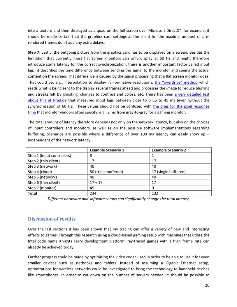
The total amount of latency therefore depends not only on the network latency, but also on the choices
of input controllers and monitors, as well as on the possible software implementations regarding
buffering. Scenarios are possible where a difference of over 100 ms latency can easily show up –
independent of the network latency.
Example Scenario 1 Example Scenario 2
Step 1 (input controllers) 8 1
Step 2 (thin client) 17 17
Step 3 (network) 40 40
Step 4 (cloud) 50 (triple buffered) 17 (single buffered)
Step 5 (network) 40 40
Step 6 (thin client) 17 + 17 17
Step 7 (monitor) 45 0
Total 234 132
Different hardware and software setups can significantly change the total latency.
Discussion of results
Over the last sections it has been shown that ray tracing can offer a variety of new and interesting
effects to games. Through this research using a cloud-based gaming setup with machines that utilize the
Intel code name Knights Ferry development platform, ray-traced games with a high frame rate can
already be achieved today.
Further progress could be made by optimizing the video codec used in order to be able to use it for even
smaller devices such as netbooks and tablets. Instead of assuming a Gigabit Ethernet setup,
optimizations for wireless networks could be investigated to bring the technology to handheld devices
like smartphones. In order to cut down on the number of servers needed, it should be possible to
21
develop support for using multiple Knights Ferry PCIe cards within a single machine. To increase image
quality, several well-known post-processing techniques like HDR bloom and depth of field could be
added. A smart solution on how to do anti-aliasing for ray tracing with high performance on the Knights
Ferry platform could also be investigated.
While the commercial use of cloud-based gaming is just starting, a scenario could be imagined in which
some gamers favor the advantages of such an approach and would use that way of gaming as their main
model. It might also be reasonable to assume that another group of gamers would like to stay at the
current model, where all games are stored and rendered locally on the gamer’s machine.
No matter which group will be the larger one, the industry is changing at an amazingly fast speed, and it
will be exciting to see how graphics in games, cloud-based gaming, and most importantly the gaming
experience will evolve over the upcoming years.
Acknowledgments
The author wishes to thank the following contributors: id Software* and Raven Software* for the
Wolfenstein* content; Alexander Reshetov, Benjamin Segovia, Alexey Soupikov, Sven Woop, and Ingo
Wald for working on the internals of the ray-tracing engine; Ram Nalla for working on the demo and
enabling the cloud-based gaming setup; Bill Mark, manager at Intel Labs; and Sean Koehl, Ram Nalla,
and Manfred Ernst for reviewing this paper.
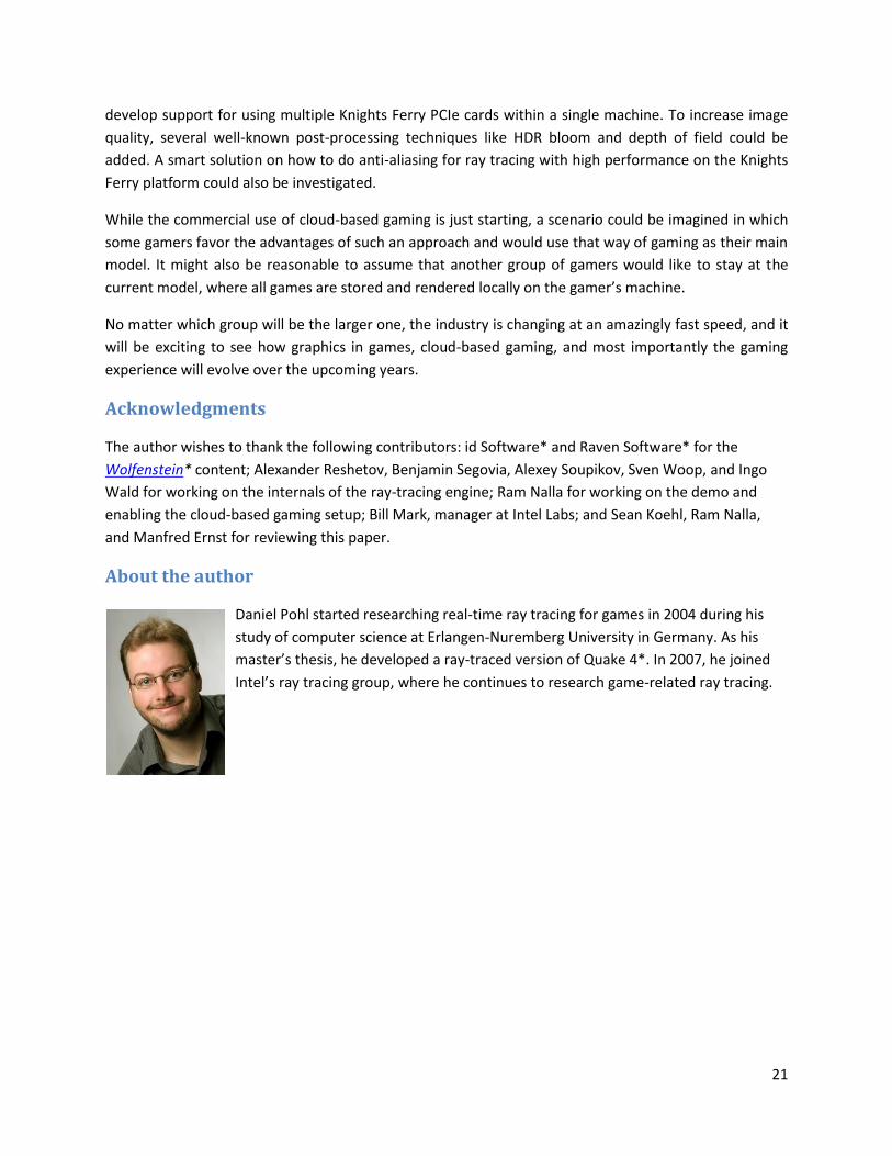
About the author
Daniel Pohl started researching real-time ray tracing for games in 2004 during his
study of computer science at Erlangen-Nuremberg University in Germany. As his
master’s thesis, he developed a ray-traced version of Quake 4*. In 2007, he joined
Intel’s ray tracing group, where he continues to research game-related ray tracing.