Embed Size (px)
Citation preview
EXPERIMENTAL CHARACTERIZATION OF HYBRID COOLED CISCO SERVERS
INCLUDING THE EFFECT OF WARM WATER COOLING
By
MD MALEKKUL ISLAM
Presented to the Faculty of the Graduate School of
The University of Texas at Arlington in Partial Fulfillment
Of the Requirements
For the Degree of
MASTER OF SCIENCE IN MECHANICAL ENGINEERING
THE UNIVERSITY OF TEXAS AT ARLINGTON
MAY 2016

ii
Copyright © by Md Malekkul Islam 2016
All Rights Reserved

iii
Acknowledgements
I would like to thank Dr. Dereje Agonafer who helped throughout my work. His
continuous guidance and support over the last two years of my study and research at
The University of Texas at Arlington helped me to cross all the obstacles.
I would like to thank Dr. Haji-Sheikh and Dr. Mulay for evaluating my work as
committee members.
I would like to give a special thanks to Ms. Sally Thompson for her immense help
throughout my stay at UT Arlington
I would also like to thank all members at EMNSPC who were helped me a lot
throughout my journey.
Finally, I would like to thank my parents who made me what I am today. I would
also like to thank my wife for her immense help.
I thank almighty god for providing me the strength and inspiration.
May 4, 2016
iv
Abstract
EXPERIMENTAL CHARACTERIZATION OF HYBRID COOLED CISCO SERVERS
INCLUDING THE EFFECT OF WARM WATER COOLING
Md Malekkul Islam, MS
The University of Texas at Arlington, 2016
Supervising Professor: Dereje Agonafer
The information technology (IT) owners are experiencing a greater cooling
challenge because of the increase in power density due to modern computational needs.
The non-uniform power density in each server is forcing the industry to use hybrid cooling
technology. Server components of different cooling requirement needs air water hybrid
cooling which offers variable design alternatives. Such hybrid cooling technology cools the
high heat generating components by using water or water based fluid, whereas, the rest of
the components are cooled by air using internal fans. Conventional air cooling is more than
sufficient for the components with less thermal demand. Air cooling is cheap, highly
available and it has better serviceability than any other cooling methods.
The objective is to optimize the cooling power of the air cooling loop of such hybrid
cooled server. As the major components are cooled by the water based fluid, the other
components generate less heat which can be cooled by much less volume of air then
supplied in air cooled server. The volume of air supplied is controlled by varying the air flow
rate through the internal fans. Also number of fan was reduced to 3 instead of 5 to minimize
the power consumption. Parameters like CPU and memory utilization are varied with the
flow rate. ASHRAE recommends that the most data centers can be maintained between
20 and 25°C, with an allowable range of 15 to 32°C. But for this type of hybrid cooling
v
servers, the processor is cooled by water. So the servers can operate at much higher inlet
air temperature. In this paper the hybrid cooled servers will be characterized also.
The server used for experimental testing has processor with 135 watt thermal
design power. Also, the server utilizes distributed pumping i.e. each cold plate has its own
pump. The test matrixes consider supply and return water temperatures, flow rate of
coolant for optimizing the cooling power consumption. The supply inlet water temperature
was varied by LabView code. Further, processor and outlet temperature was monitored for
better understanding the case scenario. The relation between supply water temperature
and different power utilization gives the data for modeling different cooling infrastructure.
This in turn, will give an idea of power savings by utilizing such energy efficient hybrid
solution for cooling servers in a datacenter.
vi
Table of Contents
Acknowledgements ............................................................................................................. iii
Abstract .............................................................................................................................. iv
List of Illustrations ............................................................................................................. viii
Chapter 1 Introduction ......................................................................................................... 1
1.1 Data Center: Energy usage and cooling efficiency .................................................. 1
1.2 Thermal Management of Data Centers .................................................................... 2
1.3 Data Center Cooling Provisioning ............................................................................ 4
1.4 Motivation ................................................................................................................. 5
1.5 Scope of Work .......................................................................................................... 6
Chapter 2 ............................................................................................................................ 7
2.1 Fans in IT Equipment ............................................................................................... 7
2.2 Fan Curve ................................................................................................................. 7
2.3 Fan Laws .................................................................................................................. 8
2.4 Fan in series and parallel ......................................................................................... 9
2.5 System Resistance ................................................................................................. 10
Chapter 3 .......................................................................................................................... 11
3.1 Server under Study ................................................................................................. 11
3.2 Test Setup .............................................................................................................. 12
3.3 Procedures ............................................................................................................. 16
Chapter 4 .......................................................................................................................... 18
4.1 Flow rate reduction test procedure ......................................................................... 18
4.2 Results .................................................................................................................... 20
Chapter 5 .......................................................................................................................... 28
5.1 Testing Procedure .................................................................................................. 28
vii
5.2 Results .................................................................................................................... 29
Chapter 6 Conclusions and Future work ........................................................................... 31
6.1 Conclusions on Air Cooling .................................................................................... 31
6.2 Conclusions on Liquid Cooling ............................................................................... 32
6.3 Future Work ............................................................................................................ 33
References ........................................................................................................................ 34
Biographical Information ................................................................................................... 37

viii
List of Illustrations
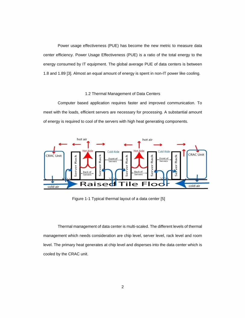
Figure 1-1 Typical thermal layout of a data center [5] ........................................................ 2
Figure 1-2 Raised-Floor Supply and Dropped-Ceiling Return Architecture ........................ 3
Figure 1-3 Environmental envelopes based on the class of data center [7] ....................... 4
Figure 2-1 Fan Performance Curve [23] ............................................................................. 8
Figure 2-2 Three fan laws [24] ............................................................................................ 8
Figure 2-3 Fans in Parallel and Series combination [23] .................................................... 9
Figure 2-4 High and low flow resistant system [23] .......................................................... 10
Figure 3-1 Cisco Server with retrofitted Asetek Cold Plate ............................................... 11
Figure 3-2 Deadband control limits ................................................................................... 12
Figure 3-3 Schematic of experimental setup to control inlet static pressure to server ..... 13
Figure 3-4 testing setup and data acquisition ................................................................... 14
Figure 3-5 K-type Penetrable Thermocouple .................................................................... 14
Figure 3-6 Thermocouple inserted with foam tape ........................................................... 15
Figure 3-7 Styrofoam for tubes ......................................................................................... 15
Figure 3-8 Front Panel of Labview .................................................................................... 16
Figure 3-9 Airflow Test Bench ........................................................................................... 17
Figure 4-1 Server attached to the Airflow Bench .............................................................. 18
Figure 4-2 System Resistance Curve ............................................................................... 20
Figure 4-3 Flow Rate vs. Fan Speed ................................................................................ 21
Figure 4-4 Flow Rate vs. PWM ......................................................................................... 21
Figure 4-5 Fan Power vs. Flow Rate ................................................................................ 22
Figure 4-6 Temperature vs. CPU Utilization with 5 fans ................................................... 23
Figure 4-7 Temperature vs. CPU Utilization with 3 fans ................................................... 24
Figure 4-8 Temperature vs. Memory Utilization with 5 fans ............................................. 25
ix
Figure 4-9 Temperature vs. Memory Utilization with 3 fans ............................................. 26
Figure 4-10 PCH Temperature vs. Utilization ................................................................... 26
Figure 5-1 Temperature vs. Inlet Temperature ................................................................. 29
1
Chapter 1
Introduction
A Data Center is a facility where large number of IT Equipment such as computer
systems, data storage units and telecommunication devices are stored. The server is the
main equipment of data center where the processes takes place. The equipment such as
server are mounted in a standardized cabinets called rack. These racks of servers
constitute many number of IT equipment. Data center requires uninterrupted power and
cooling. To maintain the required temperatures the Heating, Ventilation and Air
Conditioning (HVAC) provides the necessary cooling.
1.1 Data Center: Energy usage and cooling efficiency
Data center consumes huge amount of energy to maintain a certain temperature.
There is an increment of power consumption by data centers which is about 56%. In USA
it is reported about 36% by J. Koomey [1] in the New York Times. He also mentioned that
electricity uses by data center is 2% of total electricity use for USA. The increase in energy
usage is a concern for environmental agencies in the U.S., European Union, China and
other countries. In order to satisfy requirements new cost-cutting measures need to be
taken. This includes use of ambient air and warm water cooling etc.
American Society for Heating Refrigeration and Air Conditioning Engineers
(ASHRAE) TC 9.9 [2] Committee has developed a guidelines for design, operation,
maintenance, and efficient energy usage of data centers. The recommended temperature
zones are from 18°C (64.4°F) to 27°C (80.6°F). The humidity should be less than 60%.
Also ASHRAE A3 envelope allows IT equipment to operate at 24˚C temperature and 85%
relative humidity [3]. Anything outside of the region might show a deleterious effects on
reliability, acoustics, or performance [4].
2
Power usage effectiveness (PUE) has become the new metric to measure data
center efficiency. Power Usage Effectiveness (PUE) is a ratio of the total energy to the
energy consumed by IT equipment. The global average PUE of data centers is between
1.8 and 1.89 [3]. Almost an equal amount of energy is spent in non-IT power like cooling.
1.2 Thermal Management of Data Centers
Computer based application requires faster and improved communication. To
meet with the loads, efficient servers are necessary for processing. A substantial amount
of energy is required to cool of the servers with high heat generating components.
Figure 1-1 Typical thermal layout of a data center [5]
Thermal management of data center is multi-scaled. The different levels of thermal
management which needs consideration are chip level, server level, rack level and room
level. The primary heat generates at chip level and disperses into the data center which is
cooled by the CRAC unit.
3
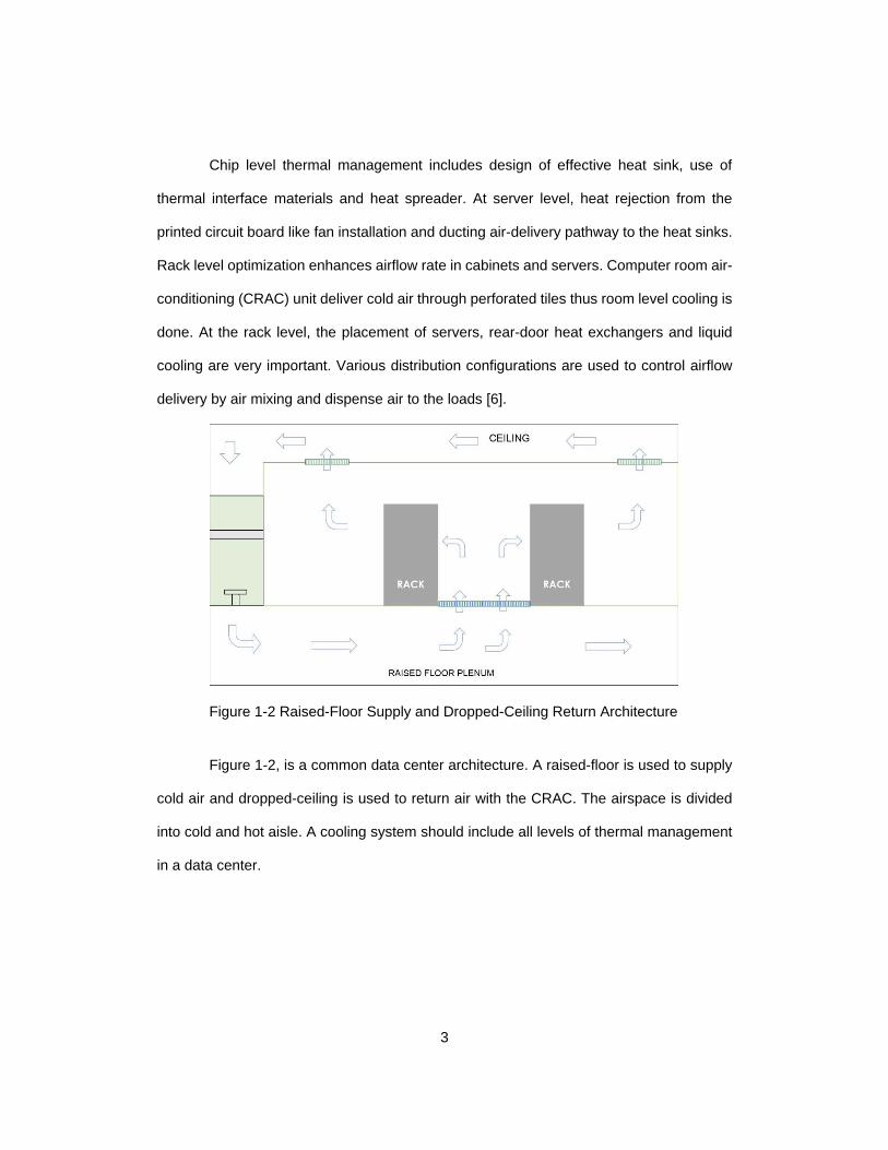
Chip level thermal management includes design of effective heat sink, use of
thermal interface materials and heat spreader. At server level, heat rejection from the
printed circuit board like fan installation and ducting air-delivery pathway to the heat sinks.
Rack level optimization enhances airflow rate in cabinets and servers. Computer room air-
conditioning (CRAC) unit deliver cold air through perforated tiles thus room level cooling is
done. At the rack level, the placement of servers, rear-door heat exchangers and liquid
cooling are very important. Various distribution configurations are used to control airflow
delivery by air mixing and dispense air to the loads [6].
Figure 1-2 Raised-Floor Supply and Dropped-Ceiling Return Architecture
Figure 1-2, is a common data center architecture. A raised-floor is used to supply
cold air and dropped-ceiling is used to return air with the CRAC. The airspace is divided
into cold and hot aisle. A cooling system should include all levels of thermal management
in a data center.
4
1.3 Data Center Cooling Provisioning
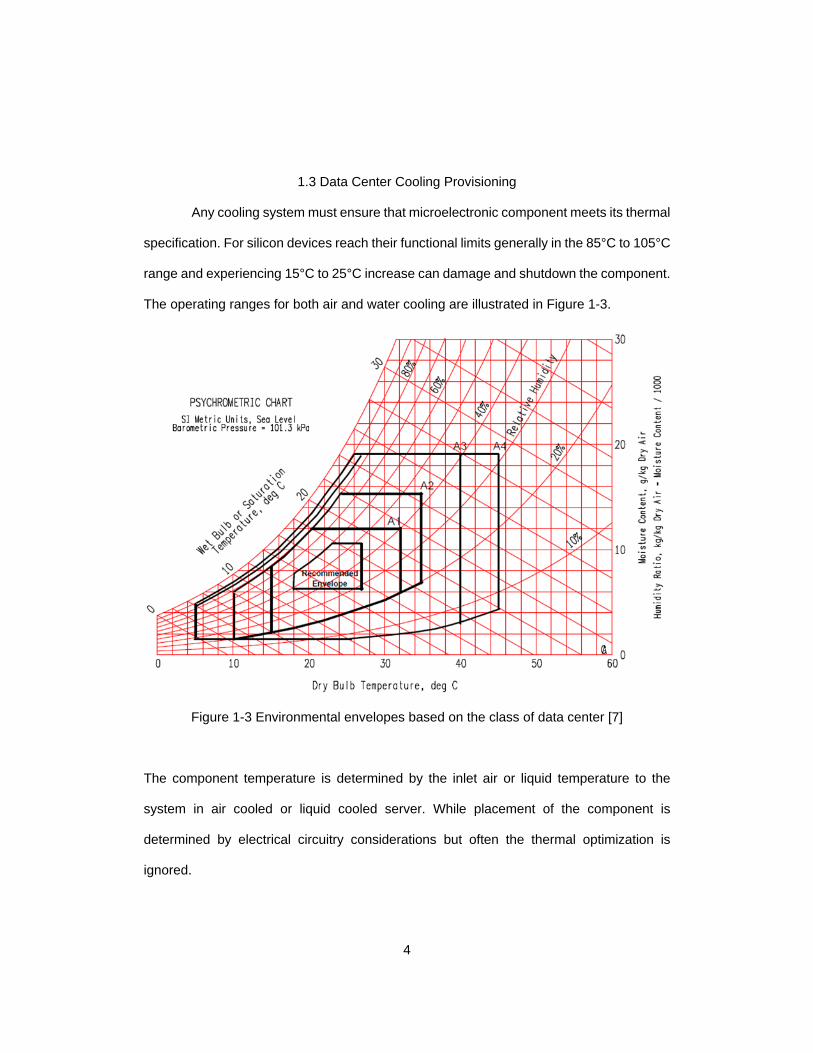
Any cooling system must ensure that microelectronic component meets its thermal
specification. For silicon devices reach their functional limits generally in the 85°C to 105°C
range and experiencing 15°C to 25°C increase can damage and shutdown the component.
The operating ranges for both air and water cooling are illustrated in Figure 1-3.
Figure 1-3 Environmental envelopes based on the class of data center [7]
The component temperature is determined by the inlet air or liquid temperature to the
system in air cooled or liquid cooled server. While placement of the component is
determined by electrical circuitry considerations but often the thermal optimization is
ignored.
5
The fans are selected to match the server’s resistance and provide required
volumetric flow rates for best cooling performance, power consumption, acoustic noise, fan
reliability and redundancies [8]. Dynamic solutions means the amount of cooling required
to maintain component operating temperatures. Component thermal sensors provide the
dynamic control over the cooling units. As the inlet temperature increases the fan unit
reacts by functioning at higher speeds.
1.4 Motivation
Microsoft has millions of servers in their data center and this was mentioned by S.
Balmer [9]. A small power savings can scale up to a huge number in these type of
companies. In search of efficient cooling technology in data centers, the industries are
looking for innovative ideas such as hybrid cooling. Pressure difference in a cold aisle and
hot aisle is necessary to improve efficiency in a data center [10].
Usually IT servers are typically designed assuming there is a zero differential
pressure between inlet and exhaust. But in reality, any change in fan speed control results
in varying volume of air through the server. Dynamic response is necessary to counter this
variation.
Liquid cooling has acceptance for cooling novel, high-powered microelectronic
device [11]. Cold plates using water as the coolant are one of the widely used liquid cooling
solutions available. The cold plate is used to remove the heat dissipated by chips mounted
on the glass ceramic substrate. As the module powers is increasing, liquid cooling is once
again being considered for thermal management of microelectronic devices [12].
Water has many advantages over air cooling such as greater heat carrying
capacity, targeted delivery and lower transport power. Also, when operating at higher
6
utilization, servers are more energy-efficient [13]. To respond to non-uniform heat
dissipation by the processor, it is necessary to use the cold plates.
This work seeks to understand the impact of air flow rate on the thermal
performance and energy consumption within a server. This information will be helpful in
optimizing the hybrid cooled server to achieve the most energy efficient use of cooling
resources.
1.5 Scope of Work
It is very important to minimize the power consumption by chassis fans because
they are parasitic loads attached to the server. The objective of this work is to reduce
cooling power of server by reducing flow rate and removing chassis fans in the server. The
overall objectives of this study are as follows:
Characterize a hybrid cooled server
Upon variation of the flow rate, the impact on server cooling efficiencies and
thermal performance
Optimize the air cooling of the server by reducing the number of fans
Study how to change the inlet temperature of liquid cooling loop
Experiment the effect of warm water cooling on the hybrid servers
7
Chapter 2
2.1 Fans in IT Equipment
The main purpose of fan is to move air. Fans can supply at a certain flow rate and
static pressure. Axial fans are mostly used in IT equipment. Axial fans can provide high
flow rate and it can work against low static pressure. Blowers are mostly used in laptops
and it works against higher static pressure.
2.2 Fan Curve
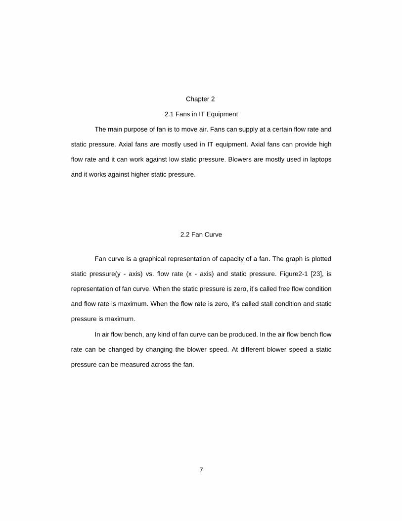
Fan curve is a graphical representation of capacity of a fan. The graph is plotted
static pressure(y - axis) vs. flow rate (x - axis) and static pressure. Figure2-1 [23], is
representation of fan curve. When the static pressure is zero, it’s called free flow condition
and flow rate is maximum. When the flow rate is zero, it’s called stall condition and static
pressure is maximum.
In air flow bench, any kind of fan curve can be produced. In the air flow bench flow
rate can be changed by changing the blower speed. At different blower speed a static
pressure can be measured across the fan.
8
Figure 2-1 Fan Performance Curve [23]
2.3 Fan Laws
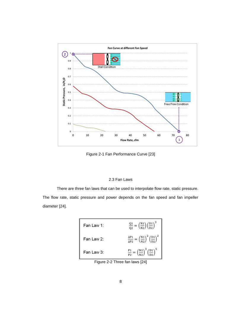
There are three fan laws that can be used to interpolate flow rate, static pressure.
The flow rate, static pressure and power depends on the fan speed and fan impeller
diameter [24].
Figure 2-2 Three fan laws [24]
9
Where Q is Flow Rate, ∆P is Pressure Drop, P is Air Power, N is fan speed in RPM
and D is Fan Impeller Diameter. As derived by Jorgenson and Bohanon [25], the laws for
incompressible version can be obtained by setting compressibility coefficient ratio equal to
unity.
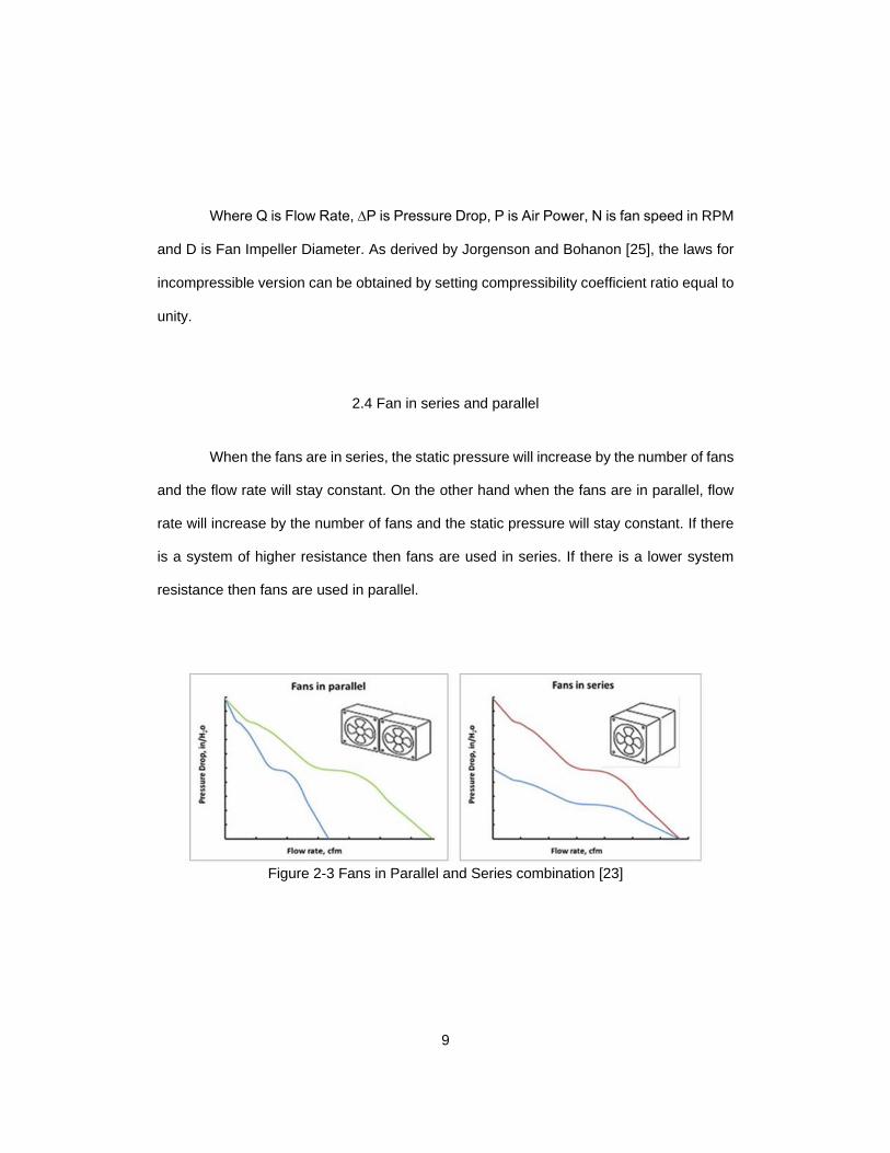
2.4 Fan in series and parallel
When the fans are in series, the static pressure will increase by the number of fans
and the flow rate will stay constant. On the other hand when the fans are in parallel, flow
rate will increase by the number of fans and the static pressure will stay constant. If there
is a system of higher resistance then fans are used in series. If there is a lower system
resistance then fans are used in parallel.
Figure 2-3 Fans in Parallel and Series combination [23]
10
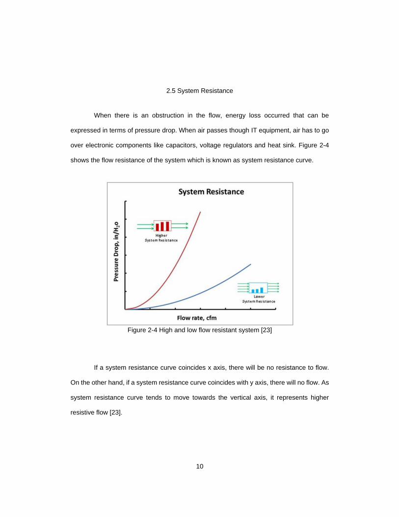
2.5 System Resistance
When there is an obstruction in the flow, energy loss occurred that can be
expressed in terms of pressure drop. When air passes though IT equipment, air has to go
over electronic components like capacitors, voltage regulators and heat sink. Figure 2-4
shows the flow resistance of the system which is known as system resistance curve.
Figure 2-4 High and low flow resistant system [23]
If a system resistance curve coincides x axis, there will be no resistance to flow.
On the other hand, if a system resistance curve coincides with y axis, there will no flow. As
system resistance curve tends to move towards the vertical axis, it represents higher
resistive flow [23].
11
Chapter 3
Experimental Set-up and Testing
The main idea for this experiment is to simulate the real world data center
conditions. To observe the effect of lower flow rate it was placed in the air flow bench where
static pressure was zero to depict an ideal condition. To experiment the effect of warm
water cooling outside room temperature was considered 250C.
3.1 Server under Study
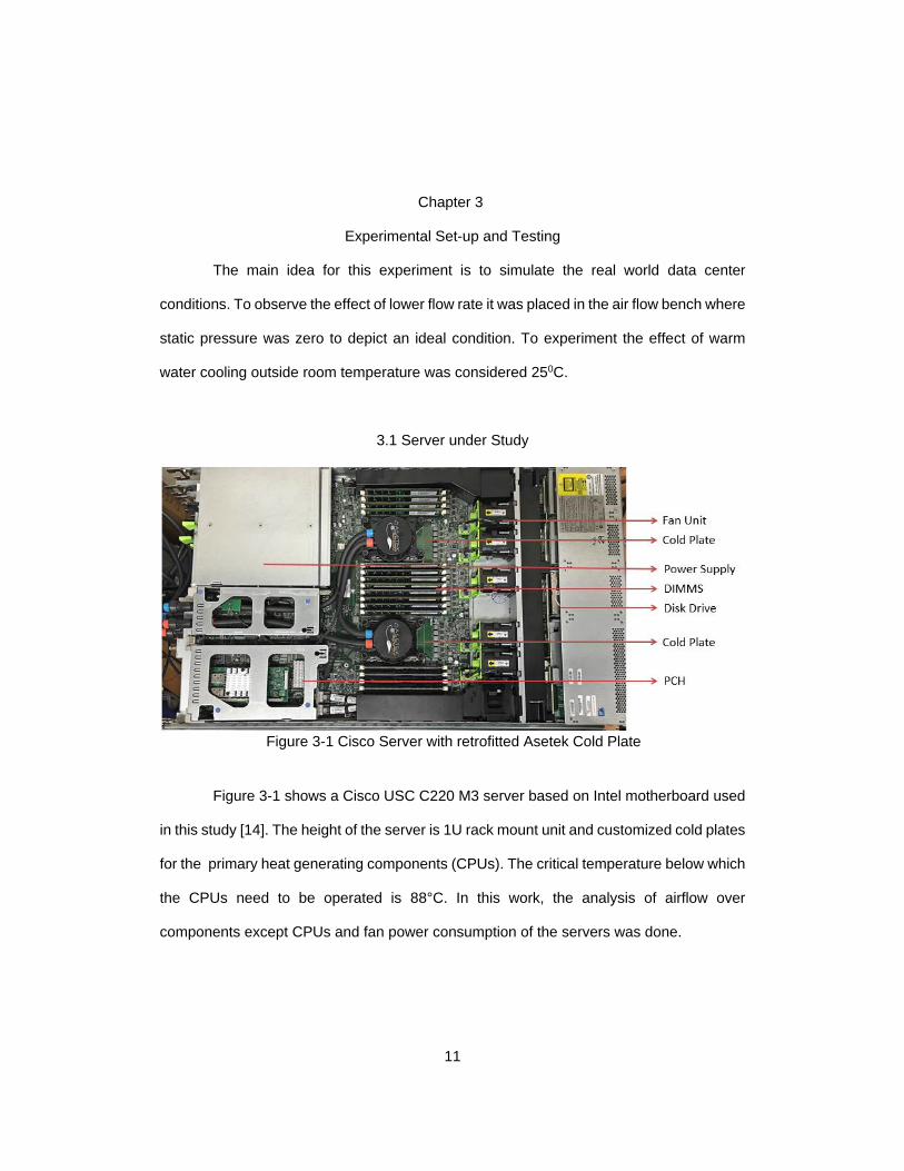
Figure 3-1 Cisco Server with retrofitted Asetek Cold Plate
Figure 3-1 shows a Cisco USC C220 M3 server based on Intel motherboard used
in this study [14]. The height of the server is 1U rack mount unit and customized cold plates
for the primary heat generating components (CPUs). The critical temperature below which
the CPUs need to be operated is 88°C. In this work, the analysis of airflow over
components except CPUs and fan power consumption of the servers was done.
12
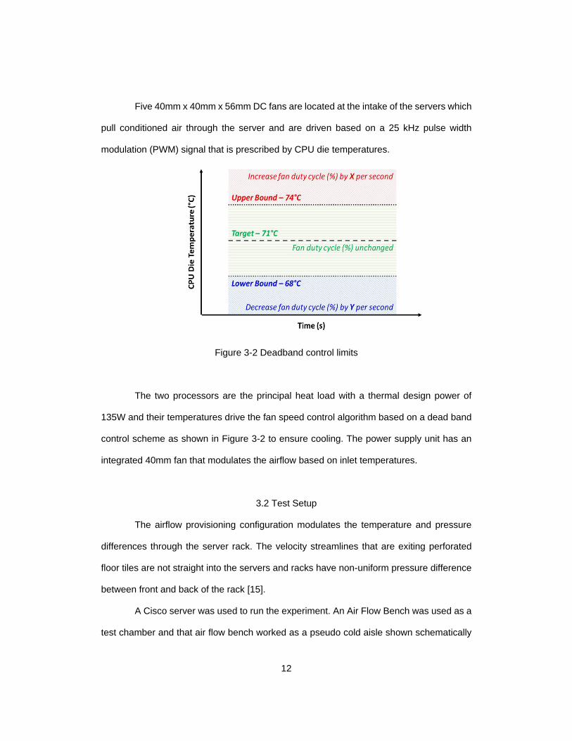
Five 40mm x 40mm x 56mm DC fans are located at the intake of the servers which
pull conditioned air through the server and are driven based on a 25 kHz pulse width
modulation (PWM) signal that is prescribed by CPU die temperatures.
Figure 3-2 Deadband control limits
The two processors are the principal heat load with a thermal design power of
135W and their temperatures drive the fan speed control algorithm based on a dead band
control scheme as shown in Figure 3-2 to ensure cooling. The power supply unit has an
integrated 40mm fan that modulates the airflow based on inlet temperatures.
3.2 Test Setup
The airflow provisioning configuration modulates the temperature and pressure
differences through the server rack. The velocity streamlines that are exiting perforated
floor tiles are not straight into the servers and racks have non-uniform pressure difference
between front and back of the rack [15].
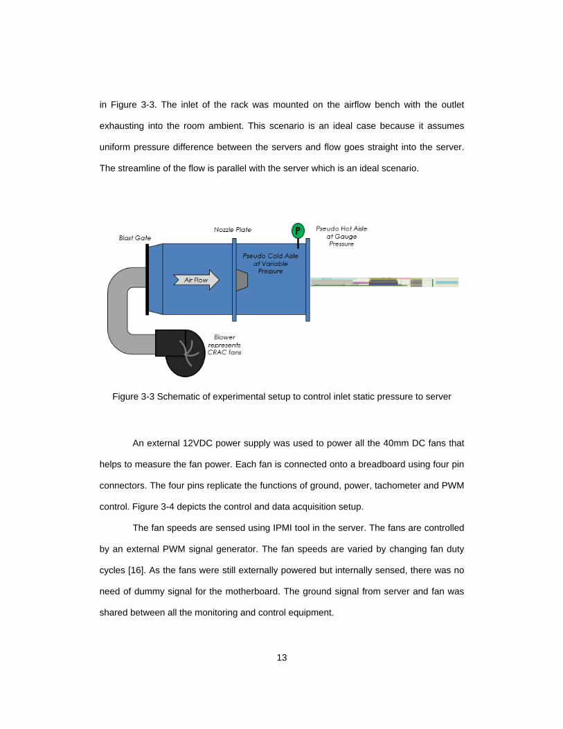
A Cisco server was used to run the experiment. An Air Flow Bench was used as a
test chamber and that air flow bench worked as a pseudo cold aisle shown schematically
13
in Figure 3-3. The inlet of the rack was mounted on the airflow bench with the outlet
exhausting into the room ambient. This scenario is an ideal case because it assumes
uniform pressure difference between the servers and flow goes straight into the server.
The streamline of the flow is parallel with the server which is an ideal scenario.
Figure 3-3 Schematic of experimental setup to control inlet static pressure to server
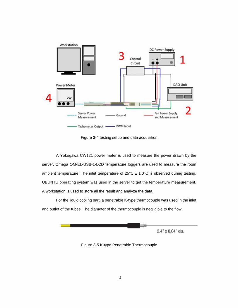
An external 12VDC power supply was used to power all the 40mm DC fans that
helps to measure the fan power. Each fan is connected onto a breadboard using four pin
connectors. The four pins replicate the functions of ground, power, tachometer and PWM
control. Figure 3-4 depicts the control and data acquisition setup.
The fan speeds are sensed using IPMI tool in the server. The fans are controlled
by an external PWM signal generator. The fan speeds are varied by changing fan duty
cycles [16]. As the fans were still externally powered but internally sensed, there was no
need of dummy signal for the motherboard. The ground signal from server and fan was
shared between all the monitoring and control equipment.
14
Figure 3-4 testing setup and data acquisition
A Yokogawa CW121 power meter is used to measure the power drawn by the
server. Omega OM-EL-USB-1-LCD temperature loggers are used to measure the room
ambient temperature. The inlet temperature of 25°C ± 1.0°C is observed during testing.
UBUNTU operating system was used in the server to get the temperature measurement.
A workstation is used to store all the result and analyze the data.
For the liquid cooling part, a penetrable K-type thermocouple was used in the inlet
and outlet of the tubes. The diameter of the thermocouple is negligible to the flow.
Figure 3-5 K-type Penetrable Thermocouple
15
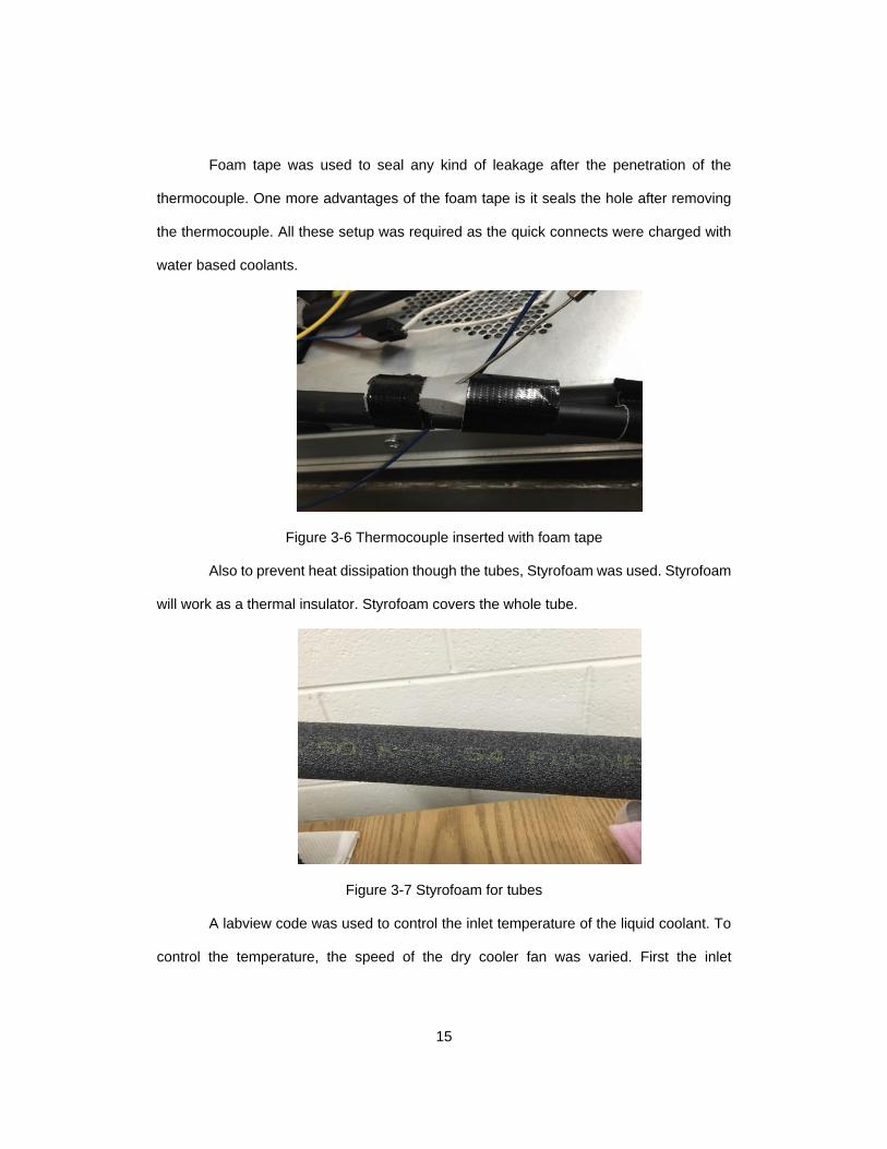
Foam tape was used to seal any kind of leakage after the penetration of the
thermocouple. One more advantages of the foam tape is it seals the hole after removing
the thermocouple. All these setup was required as the quick connects were charged with
water based coolants.
Figure 3-6 Thermocouple inserted with foam tape
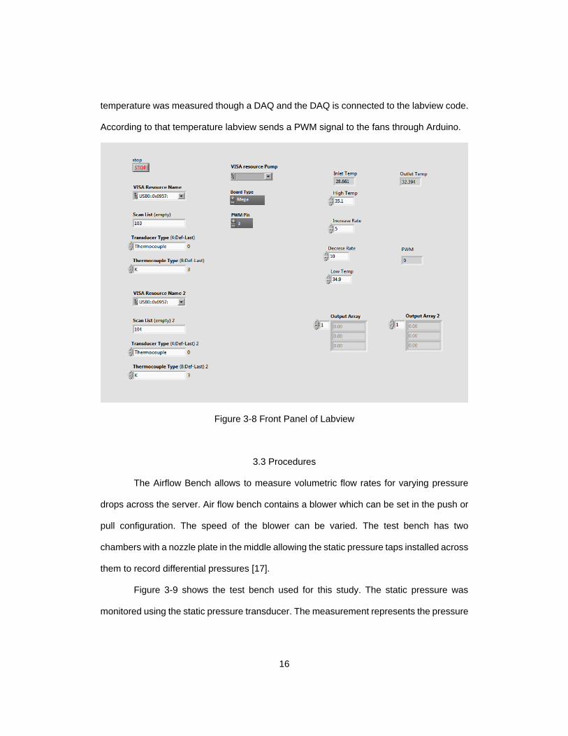
Also to prevent heat dissipation though the tubes, Styrofoam was used. Styrofoam
will work as a thermal insulator. Styrofoam covers the whole tube.
Figure 3-7 Styrofoam for tubes
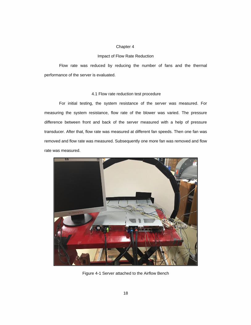
A labview code was used to control the inlet temperature of the liquid coolant. To
control the temperature, the speed of the dry cooler fan was varied. First the inlet
16
temperature was measured though a DAQ and the DAQ is connected to the labview code.
According to that temperature labview sends a PWM signal to the fans through Arduino.
Figure 3-8 Front Panel of Labview
3.3 Procedures
The Airflow Bench allows to measure volumetric flow rates for varying pressure
drops across the server. Air flow bench contains a blower which can be set in the push or
pull configuration. The speed of the blower can be varied. The test bench has two
chambers with a nozzle plate in the middle allowing the static pressure taps installed across
them to record differential pressures [17].
Figure 3-9 shows the test bench used for this study. The static pressure was
monitored using the static pressure transducer. The measurement represents the pressure

17
drop across the server. By varying the blower speed, the flow rates and pressure drops
across the server was measured with a DAQ unit. Any system or air mover is characterized
on the test bench complying to the standard referenced in [28].
The server is utilized using a synthetic load generator tool called lookbusy [29] to
create various workloads. A bash script is used to run the test for 18 hours. Native Linux
command IPMItool was used to measure the temperature of components such as CPU,
DIMMs and PCH [20]. Other native Linux commands mpstat [21] and free [22] are executed
to measure CPU utilization and memory usage during the stress. The ability to change the
flow rate allows parametric study of cooling efficiency of the fans.
Figure 3-9 Airflow Test Bench
18
Chapter 4
Impact of Flow Rate Reduction
Flow rate was reduced by reducing the number of fans and the thermal
performance of the server is evaluated.
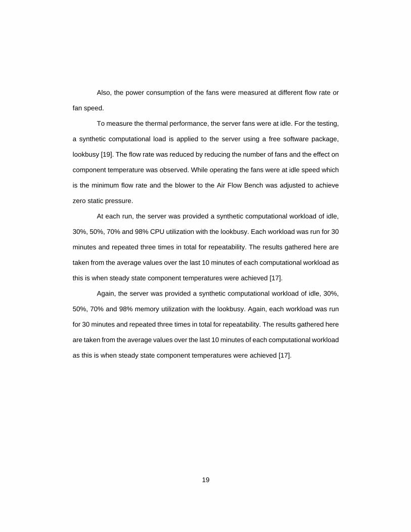
4.1 Flow rate reduction test procedure
For initial testing, the system resistance of the server was measured. For
measuring the system resistance, flow rate of the blower was varied. The pressure
difference between front and back of the server measured with a help of pressure
transducer. After that, flow rate was measured at different fan speeds. Then one fan was
removed and flow rate was measured. Subsequently one more fan was removed and flow
rate was measured.
Figure 4-1 Server attached to the Airflow Bench
19
Also, the power consumption of the fans were measured at different flow rate or
fan speed.
To measure the thermal performance, the server fans were at idle. For the testing,
a synthetic computational load is applied to the server using a free software package,
lookbusy [19]. The flow rate was reduced by reducing the number of fans and the effect on
component temperature was observed. While operating the fans were at idle speed which
is the minimum flow rate and the blower to the Air Flow Bench was adjusted to achieve
zero static pressure.
At each run, the server was provided a synthetic computational workload of idle,
30%, 50%, 70% and 98% CPU utilization with the lookbusy. Each workload was run for 30
minutes and repeated three times in total for repeatability. The results gathered here are
taken from the average values over the last 10 minutes of each computational workload as
this is when steady state component temperatures were achieved [17].
Again, the server was provided a synthetic computational workload of idle, 30%,
50%, 70% and 98% memory utilization with the lookbusy. Again, each workload was run
for 30 minutes and repeated three times in total for repeatability. The results gathered here
are taken from the average values over the last 10 minutes of each computational workload
as this is when steady state component temperatures were achieved [17].
20
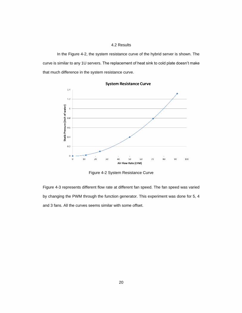
4.2 Results
In the Figure 4-2, the system resistance curve of the hybrid server is shown. The
curve is similar to any 1U servers. The replacement of heat sink to cold plate doesn’t make
that much difference in the system resistance curve.
Figure 4-2 System Resistance Curve
Figure 4-3 represents different flow rate at different fan speed. The fan speed was varied
by changing the PWM through the function generator. This experiment was done for 5, 4
and 3 fans. All the curves seems similar with some offset.

21
Figure 4-3 Flow Rate vs. Fan Speed
Figure 4-4 shows the same graph as before but this is flow rate vs. PWM of the fans. The
PWM of the fans were controlled by the function generator. It has the same pattern as the
previous graph.
Figure 4-4 Flow Rate vs. PWM
22
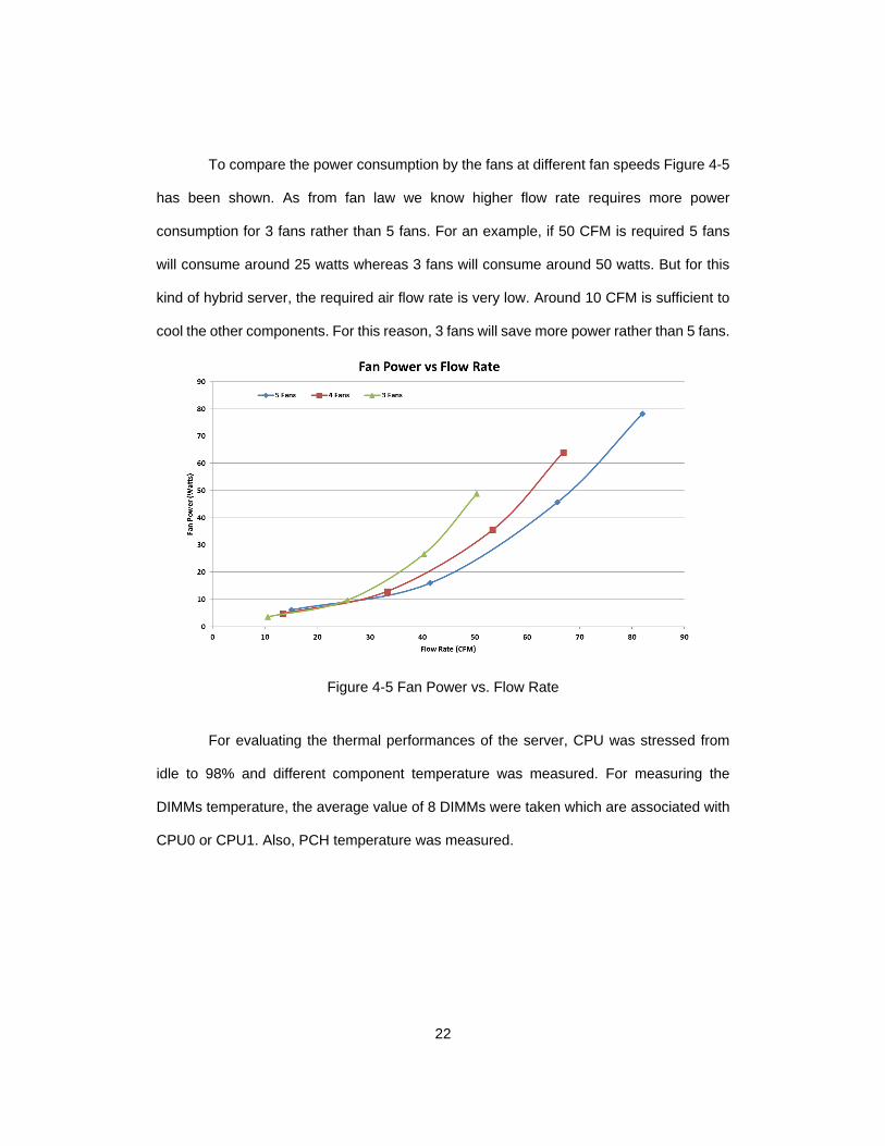
To compare the power consumption by the fans at different fan speeds Figure 4-5
has been shown. As from fan law we know higher flow rate requires more power
consumption for 3 fans rather than 5 fans. For an example, if 50 CFM is required 5 fans
will consume around 25 watts whereas 3 fans will consume around 50 watts. But for this
kind of hybrid server, the required air flow rate is very low. Around 10 CFM is sufficient to
cool the other components. For this reason, 3 fans will save more power rather than 5 fans.
Figure 4-5 Fan Power vs. Flow Rate
For evaluating the thermal performances of the server, CPU was stressed from
idle to 98% and different component temperature was measured. For measuring the
DIMMs temperature, the average value of 8 DIMMs were taken which are associated with
CPU0 or CPU1. Also, PCH temperature was measured.
23
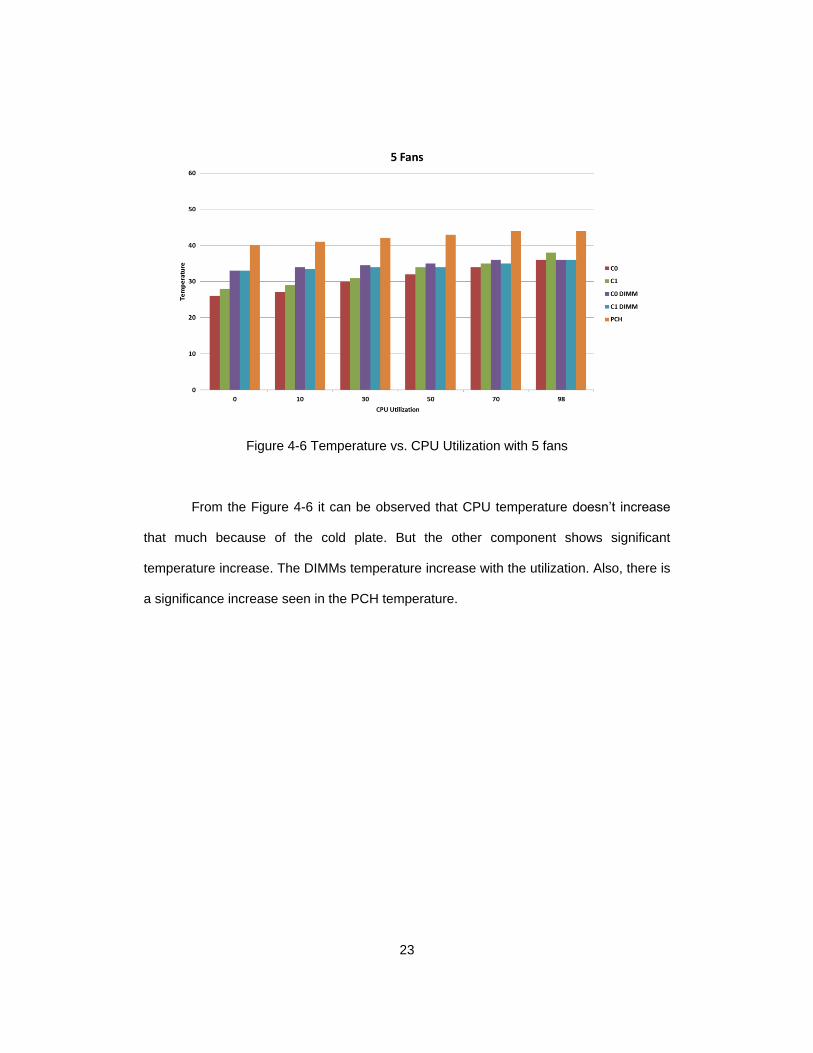
Figure 4-6 Temperature vs. CPU Utilization with 5 fans
From the Figure 4-6 it can be observed that CPU temperature doesn’t increase
that much because of the cold plate. But the other component shows significant
temperature increase. The DIMMs temperature increase with the utilization. Also, there is
a significance increase seen in the PCH temperature.
24
.
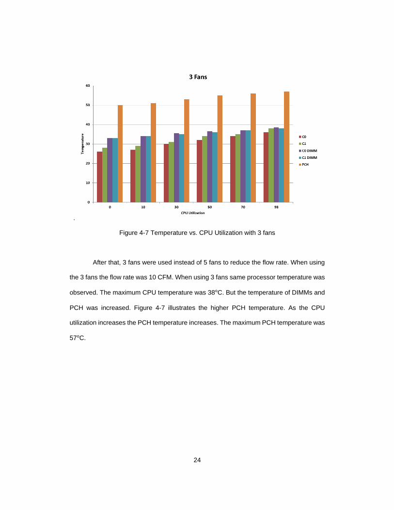
Figure 4-7 Temperature vs. CPU Utilization with 3 fans
After that, 3 fans were used instead of 5 fans to reduce the flow rate. When using
the 3 fans the flow rate was 10 CFM. When using 3 fans same processor temperature was
observed. The maximum CPU temperature was 38°C. But the temperature of DIMMs and
PCH was increased. Figure 4-7 illustrates the higher PCH temperature. As the CPU
utilization increases the PCH temperature increases. The maximum PCH temperature was
57°C.

25
Figure 4-8 Temperature vs. Memory Utilization with 5 fans
In this case instead of CPU, memory was utilized from idle to 98% with help of
lookbusy. CPU temperature was similar as the previous cases. But higher DIMMs
temperature was observed. As the memory utilization increased the DIMMs temperature
increased too. The maximum DIMM temperature was 44°C. Also, The PCH temperature
was 46°C. All the temperatures are way below the critical temperature which make sure
the reliability and performance of the components.
26
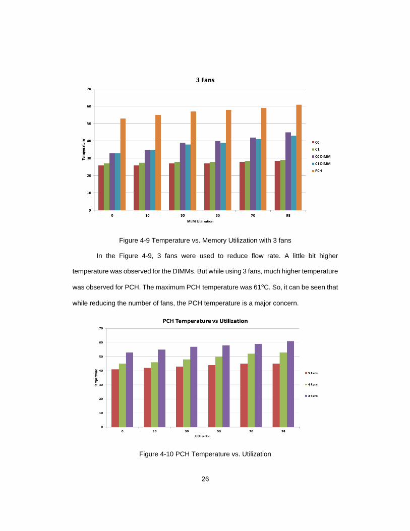
Figure 4-9 Temperature vs. Memory Utilization with 3 fans
In the Figure 4-9, 3 fans were used to reduce flow rate. A little bit higher
temperature was observed for the DIMMs. But while using 3 fans, much higher temperature
was observed for PCH. The maximum PCH temperature was 61°C. So, it can be seen that
while reducing the number of fans, the PCH temperature is a major concern.
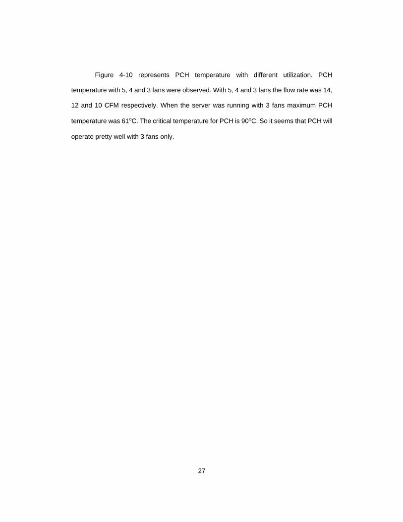
Figure 4-10 PCH Temperature vs. Utilization
27
Figure 4-10 represents PCH temperature with different utilization. PCH
temperature with 5, 4 and 3 fans were observed. With 5, 4 and 3 fans the flow rate was 14,
12 and 10 CFM respectively. When the server was running with 3 fans maximum PCH
temperature was 61°C. The critical temperature for PCH is 90°C. So it seems that PCH will
operate pretty well with 3 fans only.
28
Chapter 5
Impact of Warm Water Cooling
5.1 Testing Procedure
Understanding the impact of warm water cooling is very important for this kind of
processor which has very high heat generating capacity. The CPU was stressed with
lookbusy. The temperature was measured by IPMItool. The fans were at idle speed.
A synthetic workload of 98% CPU utilization with the lookbusy was given to the
server. Each workload was run for 30 minutes and repeated three times in total for
repeatability. The results gathered here are taken from the average values over the
last 10 minutes of each computational workload as this is when steady state CPU
temperatures were achieved.
To maintain steady inlet temperature labview code was used. First, the inlet
temperature was measured with a penetrable K-type thermocouple. Then the
temperature value was used in the labview code. A dead band control was used to
monitor the temperature and give output signal accordingly. If the temperature was
higher than the target temperature, an output signal of higher PWM generated. On the
other hand if the temperature was lower than the target temperature, an output signal
of lower PWM generated. Then the output PWM signal was sent to the miniature dry
cooler fan with the help of Arduino. Arduino was connected to the labview code. All of
these process was automated.
29
5.2 Results
The inlet temperature of the cold plate was varied from 30°C to 50°C with an
increment of 5°C. The output parameters that were monitored are outlet temperature,
CPU0 and CPU1 temperature. CPU0 was in the upstream and CPU1 was in the
downstream.
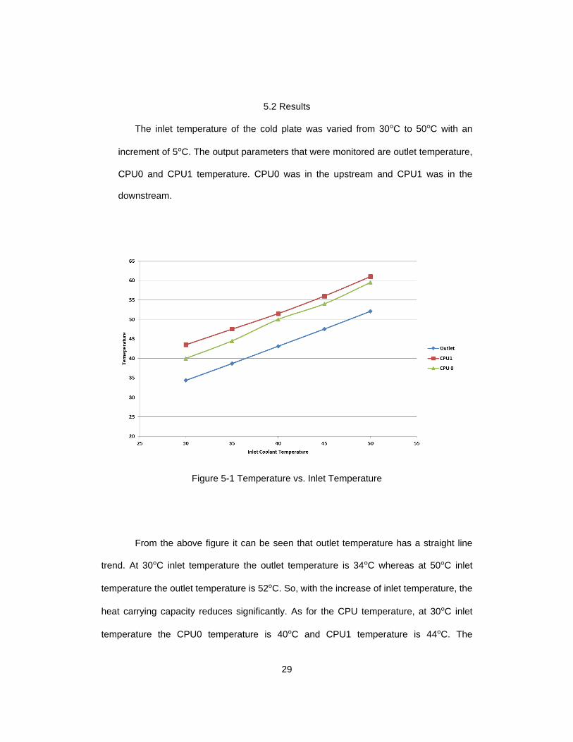
Figure 5-1 Temperature vs. Inlet Temperature
From the above figure it can be seen that outlet temperature has a straight line
trend. At 30°C inlet temperature the outlet temperature is 34°C whereas at 50°C inlet
temperature the outlet temperature is 52°C. So, with the increase of inlet temperature, the
heat carrying capacity reduces significantly. As for the CPU temperature, at 30°C inlet
temperature the CPU0 temperature is 40°C and CPU1 temperature is 44°C. The
30
temperature increase has a linear trend. With the higher inlet temperature, the difference
between CPU0 and CPU1 decreases. At, 50°C inlet temperature, CPU0 temperature is
59°C and CPU1 has 61°C. The critical temperature for the processor is 88°C. So even at
50°C inlet temperature the processor should work fine. The performance and reliability
should not be an issue at this temperature.

31
Chapter 6 Conclusions and Future work
6.1 Conclusions on Air Cooling
In this study the effects of different airflow rate going through the server is studied.
In the process of reducing the air flow rate, the number of fans were also reduced. This
study will a new idea of optimizing hybrid cooled server. A truly optimized system will
require balancing between air cooling part and liquid cooling part as well. From the results
showed in here it is clear that hybrid cooled server required a reduced amount of air flow
then air cooled server.
The overall goal of the study is to minimize the total cooling power consumption.
Some significant overall conclusions can be drawn from the experimental study performed
on the Cisco servers. There can be an overall 40% energy savings when using 3 fans.
Each fan consumes a maximum of 9W. If it is possible to reduce 2 fans that will
save around 18W. Reducing 2 fans will reduce the flow rate which can cause an increase
in component temperature.
The power saving greatly depends on the fan control algorithm. In this case fan
algorithm is set based on the processor temperature but it needs to set on the basis of
PCH temperature because the main heat generating component is the PCH as the
processor is cooled by the liquid cooling.
From the experiments it can deduced that, Using 3 fans at idle speed will cause
the enough air cooling for the components. It can be seen that the maximum PCH
32
temperature was 61°C. Other components like DIMMs were way below the critical
temperature. The maximum DIMM temperature was 46°C.
Also it was seen that PCH usually generate a constant heat. It doesn’t change that
much with CPU or memory utilization. For redundancy, 3 fans can always ramp up and
produce enough air flow. The maximum air flow for 3 fans is 50 CFM. In a sense that will
require more power than 5 fans but when they are running at idle 3 fans will require less
power. For all of this a dynamic fan control algorithm is required.
6.2 Conclusions on Liquid Cooling
On the other hand, for the liquid cooling experiment it can be deduced that these
servers can run at a much higher inlet temperature. It was observed that flow rate was
critical parameter to consider when warm water cooling experiment was done.
From the experiment, the inlet temperature was at 50°C and the maximum
processor temperature was 61°C which is way below the critical temperature. The critical
temperature for this kind of processor is 88°C. So it is safe to say that these server can run
at 50°C inlet temperature as well.
As we know cooling rate or flow rate is important factor in warm water cooling. The
flow rate was at maximum when the inlet temperature was at 50°C. That’s why the
processor temperature was under 65°C.

33
6.3 Future Work
To find the optimized position for the fans
Introducing a ducting system so that more air can go through the PCH heat sink
Study the effect of raised inlet air temperature
Study the tradeoff between cooling power and leakage current
Experiment with reduced coolant flow rate
Study the failure case scenario of fans and pumps as well

34
References
[1] [Online]. Available: "http://www.koomey.com/post/8323374335".
[2] "2008 ASHRAE Environmental Guidelines for Datacom Equipment," ASHRAE TC 9.9 committee, 2008.
[3] Prabjit Singh, Levente Klein, Dereje Agonafer, Kanan Pujara;, "Effect of Relative Humidity, Temperature and Gaseous and Particulate Contaminations on Information Technology Equipment Reliability," in InterPACK/ICNMM, San Francisco, 2015.
[4] Thermal Guidelines for Data Processing Environments– Expanded Data Center Classes and Usage Guidance Whitepaper prepared by ASHRAE Technical Committee (TC) 9.9 Mission Critical Facilities, Technology Spaces, and Electronic Equipment, 2011.
[5] [Online]. Available: http://datacenter.cit.nih.gov/interface/interface240/energy_efficiency.html
[6] K. Dunlap and N. Rasmussen, “Choosing Between Room , Row , and Rack-based Cooling for Data Centers,” p. 18, 2012.
[7] ASHRAE TC 9.9, Thermal Guidelines for Data Processing Environments, Atlanta: American Society of Heating, Refrigeration and Air-Conditioning Engineers Inc., 2005.
[8] ASHRAE Technical Committe 9.9, “IT Equipment Thermal Management and Controls,” Am. Soc. Heating, Refrig. Air-Conditioning Eng. Inc, ASHRAE TC 9.9 Whitepaper, 2012.
[9] [Online]. Available: http://www.datacenterknowledge.com/archives/2013/07/15/ballmer-microsoft-has-1-million-servers/
[10] E. Frachtenberg, D. Lee, M. Magarelli, V. Mulay, and J. Park, “Thermal design in the open compute datacenter,” Intersoc. Conf. Therm. Thermomechanical Phenom. Electron. Syst. ITHERM, vol. 94025, pp. 530–538, 2012.
[11] B. Agostini, M. Fabbri, J. E. Park, L. Wojtan, J. R. Thome and B. Michel, "State of the art of high heat flux cooling technologies," Heat Transfer Engineering, vol. 28, no. 4, pp. 258-281, 2007.
35
[12] R. R. Schmidt, "Liquid Cooling is Back," 1 August 2005. [Online]. Available: http://www.electronics-cooling.com/2005/08/liquid-cooling-is-back/. [Accessed 23 January 2015].
[13] J. Fernandes, S. Ghalambor, A. Docca, C. Aldham, D. Agonafer, E. Chenelly, B. Chan and M. Ellsworth, "Combining Computational Fluid Dynamics (CFD) and Flow Network Modeling (FNM) for Design of a Multi-Chip Module (MCM) Cold Plate," in ASME International Electronic Packaging Technical Conference and Exhibition, Burlingame, CA, USA, 2013.
[14] [Online]. Available: http://www.cisco.com/c/en/us/products/servers-unified-computing/ucs-c220-m3-rack-server/index.html
[15] P. Kumar, Y. Joshi, M. K. Patterson, R. Steinbrecher, and M. Mena, “Cold Aisle Air Distribution in a Raised Floor Data Center with Heterogenous Opposing Orientation Racks,” InterPACK, pp. 1–8, 2011.
[16] Intel, “4-Wire Pulse Width Modulation (PWM) Controlled Fans,” 2005. [Online]. Available: http://www.formfactors.org/developer%5Cspecs%5C4_Wire_PWM_Spec.pdf. [Accessed: 20-Nov-2015].
[17] A. Siddarth, "Experimental Study on Effects Of Segregated Cooling Provisioning on Thermal Performance of Information Technology Servers In Air Cooled Data Centers," University of Texas at Arlington.
[18] AMCA 210-99 and A. 51-99, “Laboratory Methods of Testing Fans for Aerodynamic Performance Rating,” Air Mov. Control Assoc. Int. …, vol. 552, 1999.
[19] D. Carraway, “‘lookbusy - a synthetic load generator,’ [Online].” p. https://devin.com/lookbusy/, 2013.
[20] [Online]. Available: http://linux.die.net/man/1/ipmitool
[21] “"mpstat(1): Report processors related statistics - Linux man page.” [Online]. Available: http://linux.die.net/man/1/mpstat. [Accessed: 20-Nov-2015].
[22] “free(1): amount of free/used memory in system - Linux man page.” [Online]. Available: http://linux.die.net/man/1/free. [Accessed: 20-Nov-2015].
[23] B. Nagendran, " Improving Cooling Efficiency Of Servers By Replacing Smaller Chassis Enclosed Fans With Larger Rack-Mount Fans," University of Texas at Arlington.
36
[24] [Online]. Available: https://en.wikipedia.org/wiki/Affinity_laws.
[25] R. Jorgensen and H.R. Bahonon, "Compressibility and Fan Laws", ASHRAE Paper No. 2333.

37
Biographical Information
Md Malekkul Islam, has received her Bachelor of Science in Mechanical
Engineering degree from Bangladesh University of Engineering and Technology, Dhaka,
Bangladesh. He has completed her Masters of Science in Mechanical Engineering from
the University of Texas at Arlington in May 2016.
Malek has always been interested in Computational Fluid Dynamics, HVAC
systems and Machine design. His research interests have always been into Fluid flow and
Heat Transfer, Thermal Sciences and Design.
During his Master’s program he has worked in thermal management of data
centers. He has associated himself with various industry collaborated research projects
and studied various topics like air cooling, liquid cooling and direct/indirect evaporative
cooling etc. He has worked in experimental and CFD characterization of Cisco servers,
thermal power optimization technique and determination of die temperature. He has gained
theoretical background knowledge of CFD and worked data center specific CFD codes like
6SigmaDC, Icepak and FloTherm.