Embed Size (px)
Citation preview
Budownictwo i Architektura 2 (2008) 79-94
Experimental and numerical investigation of plywood progressive failure in CT tests
Ivelin V. Ivanov*,**, Tomasz Sadowski**, Magdalena Filipiak**, Marcin Kneć***
*Department of Engineering Mechanics, University of Rousse, 8 Studentska str., Rousse 7017, Bulgaria
**Lublin University of Technology, Faculty of Civil and Sanitary Engineering, Department of Solid Mechanics, Nadbystrzycka 40, 20-618 Lublin, Poland
***Lublin University of Technology, Faculty of Mechanical Engineering, Applied Mechanics Department, Nadbystrzycka 36, 20-618 Lublin, Poland
Abstract: The plywood is considered as a layered cross-ply unidirectional fibre reinforced composite. The experimental Compact Tension (CT) tests carried out in different directions of plywood fibre orientation show that the characteristics of damages are fibre bundle rupture, matrix cracking along the fibres, and delami-nation at the ply interlayers of glue. The plywood CT specimens are modelled by continuum shell and cohesive finite elements with damage evolution in material models. The Finite Element (FE) model simulates the experimental behaviour of plywood samples very well and allows deep investigation of the different types of damage development and interaction. The FE model of plywood is useful for its lay-up optimization and for development of very efficient in large-scale simulations computational models of plywood.
Key words: plywood, veneer, progressive failure, damage, finite element model, finite element simulation.
1. IntroductionPlywood is very popular material in civil engineering and furniture industry,
because it is comparatively cheap, strong, and lightweight material. Its strength and progressive failure resistance are very important for wooden houses survivability in earthquake, tornado, and hurricane events [1-3]. The progressive failure of plywood, however, is complicated because of its structure as a layered natural composite which is very similar to polymeric unidirectional fibre reinforced composites.
Plywood is made from thin sheets of timber – veneer, called also plies. The timber is orthotropic fibre material with well pronounced difference in elastic and mechanical properties between the longitudinal (L) to the fibres direction and the tangential direction (T) to the annually growth rings. The veneers are cut by rotating the trunks and therefore they are oriented in the LT-plane of timber material with a normal in radial (R) direction of the log. They are stacked together with the fibre direction of each ply perpendicular to the fibre direction of its adjacent ones and usually the plywood has an odd number of plies. The veneers are bonded together
Ivelin V. Ivanov, Tomasz Sadowski, Magdalena Filipiak, Marcin Kneć80
under heat and pressure with strong adhesive, which makes the plywood a type of layered composite material. Plywood is used in many applications as a lumber of a higher quality because of its resistance to cracking, breaking, twisting and warping although the pure wood is very brittle material.
The Finite Element (FE) method was developed in recent few decades as a superior numerical method that could produce computer simulations of different phenomena of the real world. This allows many researchers to use the FE tech-nique to investigate some problem that is not easy to be directly observed and its parameters to be measured. The FE method is best developed for Solid and Structure mechanics and it is enriched with many material models, including damage models as well as specific structure finite elements like cohesive elements, continuum shell elements, etc.
In this paper the problem of progressive failure in plywood material is investi-gated by Compact Tension (CT) experimental tests and FE analysis. The plywood specimens are made from spruce and pine veneers. The gradual degradation and fracture process of this material is very complicated. It obeys both description of damage growth in plies and delamination of composite layers. The numerical simu-lation of the problem was done by application of FE technique and ABAQUS™ commercial code.
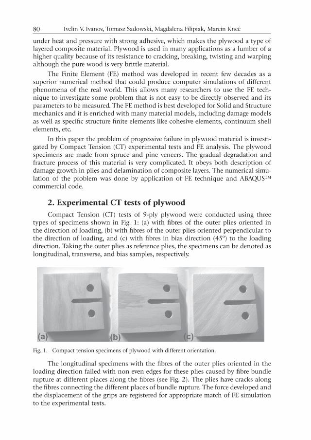
2. Experimental CT tests of plywoodCompact Tension (CT) tests of 9-ply plywood were conducted using three
types of specimens shown in Fig. 1: (a) with fibres of the outer plies oriented in the direction of loading, (b) with fibres of the outer plies oriented perpendicular to the direction of loading, and (c) with fibres in bias direction (45º) to the loading direction. Taking the outer plies as reference plies, the specimens can be denoted as longitudinal, transverse, and bias samples, respectively.
Fig. 1. Compact tension specimens of plywood with different orientation.
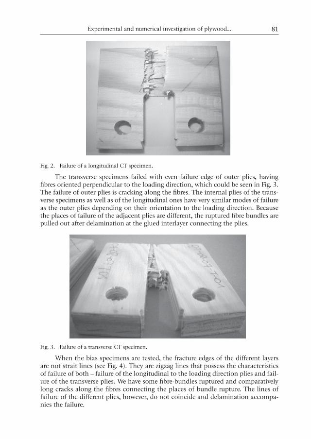
The longitudinal specimens with the fibres of the outer plies oriented in the loading direction failed with non even edges for these plies caused by fibre bundle rupture at different places along the fibres (see Fig. 2). The plies have cracks along the fibres connecting the different places of bundle rupture. The force developed and the displacement of the grips are registered for appropriate match of FE simulation to the experimental tests.
Experimental and numerical investigation of plywood... 81
Fig. 2. Failure of a longitudinal CT specimen.
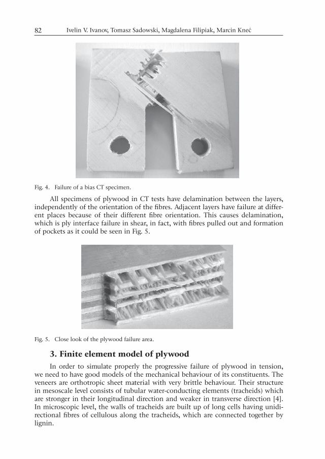
The transverse specimens failed with even failure edge of outer plies, having fibres oriented perpendicular to the loading direction, which could be seen in Fig. 3. The failure of outer plies is cracking along the fibres. The internal plies of the trans-verse specimens as well as of the longitudinal ones have very similar modes of failure as the outer plies depending on their orientation to the loading direction. Because the places of failure of the adjacent plies are different, the ruptured fibre bundles are pulled out after delamination at the glued interlayer connecting the plies.
Fig. 3. Failure of a transverse CT specimen.
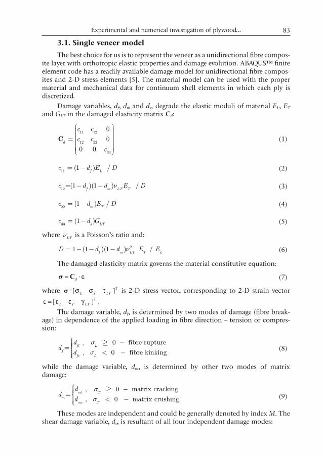
When the bias specimens are tested, the fracture edges of the different layers are not strait lines (see Fig. 4). They are zigzag lines that possess the characteristics of failure of both – failure of the longitudinal to the loading direction plies and fail-ure of the transverse plies. We have some fibre-bundles ruptured and comparatively long cracks along the fibres connecting the places of bundle rupture. The lines of failure of the different plies, however, do not coincide and delamination accompa-nies the failure.
Ivelin V. Ivanov, Tomasz Sadowski, Magdalena Filipiak, Marcin Kneć82
Fig. 4. Failure of a bias CT specimen.
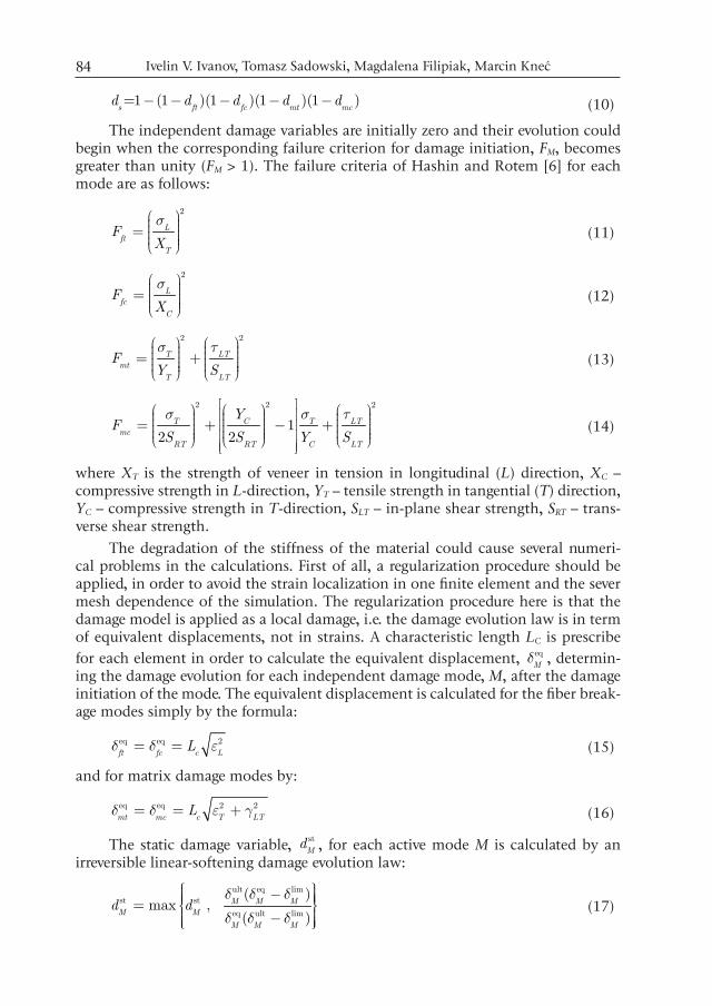
All specimens of plywood in CT tests have delamination between the layers, independently of the orientation of the fibres. Adjacent layers have failure at differ-ent places because of their different fibre orientation. This causes delamination, which is ply interface failure in shear, in fact, with fibres pulled out and formation of pockets as it could be seen in Fig. 5.
Fig. 5. Close look of the plywood failure area.
3. Finite element model of plywoodIn order to simulate properly the progressive failure of plywood in tension,
we need to have good models of the mechanical behaviour of its constituents. The veneers are orthotropic sheet material with very brittle behaviour. Their structure in mesoscale level consists of tubular water-conducting elements (tracheids) which are stronger in their longitudinal direction and weaker in transverse direction [4]. In microscopic level, the walls of tracheids are built up of long cells having unidi-rectional fibres of cellulous along the tracheids, which are connected together by lignin.
Experimental and numerical investigation of plywood... 83
3.1. Single veneer model
The best choice for us is to represent the veneer as a unidirectional fibre compos-ite layer with orthotropic elastic properties and damage evolution. ABAQUS™ finite element code has a readily available damage model for unidirectional fibre compos-ites and 2-D stress elements [5]. The material model can be used with the proper material and mechanical data for continuum shell elements in which each ply is discretized.
Damage variables, df, dm and ds, degrade the elastic moduli of material EL, ET and GLT in the damaged elasticity matrix Cd:
11 12
12 22
33
0
0
0 0d
c c
c c
c
æ ö÷ç ÷ç ÷ç ÷ç= ÷ç ÷ç ÷÷ç ÷ç ÷çè ø
C
(1)
11(1 ) /
f Lc d E D= -
(2)
12=(1 )(1 ) /
f m LT Tc d d E Dn- -
(3)
22(1 ) /
m Tc d E D= - (4)
33(1 )
s LTc d G= - (5)
where LT
n is a Poisson’s ratio and:
21 (1 )(1 ) / f m LT T L
D d d E En= - - - (6)
The damaged elasticity matrix governs the material constitutive equation:
s ed= ⋅C (7)
where T=[ ]s L T LTσ σ τ is 2-D stress vector, corresponding to 2-D strain vector T[ ]e L T LTε ε γ= .
The damage variable, df, is determined by two modes of damage (fibre break-age) in dependence of the applied loading in fibre direction – tension or compres-sion:
, 0 fibre rupture=
, 0 fibre kinkingft L
ffc L
dd
d
ss
ìï -ïïíï < -ïïî
³
(8)
while the damage variable, dm, is determined by other two modes of matrix damage:
, 0 matrix cracking=
, 0 matrix crushingmt T
mmc T
dd
d
ss
ìï -ïïíï < -ïïî
³
(9)
These modes are independent and could be generally denoted by index M. The shear damage variable, ds, is resultant of all four independent damage modes:
Ivelin V. Ivanov, Tomasz Sadowski, Magdalena Filipiak, Marcin Kneć84
=1 (1 )(1 )(1 )(1 ) s ft fc mt mc
d d d d d- - - - - (10)
The independent damage variables are initially zero and their evolution could begin when the corresponding failure criterion for damage initiation, FM, becomes greater than unity (FM > 1). The failure criteria of Hashin and Rotem [6] for each mode are as follows:
2
Lft
T
FX
sæ ö÷ç ÷ç= ÷ç ÷ç ÷è ø (11)
2
Lfc
C
FX
sæ ö÷ç ÷ç= ÷ç ÷ç ÷è ø (12)
2 2
T LTmt
T LT
FY S
s tæ ö æ ö÷ ÷ç ç÷ ÷ç ç= +÷ ÷ç ç÷ ÷ç ç÷ ÷è ø è ø (13)
2 2 2
12 2
T C T LTmc
RT RT C LT
YF
S S Y S
s s té ùæ ö æ ö æ öê ú÷ ÷ ÷ç ç ç÷ ÷ ÷ç ç ç= + - +ê ú÷ ÷ ÷ç ç ç÷ ÷ ÷ç çê ú ç ÷÷ ÷ è øè ø è øê úë û
(14)
where XT is the strength of veneer in tension in longitudinal (L) direction, XC – compressive strength in L-direction, YT – tensile strength in tangential (T) direction, YC – compressive strength in T-direction, SLT – in-plane shear strength, SRT – trans-verse shear strength.
The degradation of the stiffness of the material could cause several numeri-cal problems in the calculations. First of all, a regularization procedure should be applied, in order to avoid the strain localization in one finite element and the sever mesh dependence of the simulation. The regularization procedure here is that the damage model is applied as a local damage, i.e. the damage evolution law is in term of equivalent displacements, not in strains. A characteristic length LC is prescribe for each element in order to calculate the equivalent displacement, eq
Md , determin-
ing the damage evolution for each independent damage mode, M, after the damage initiation of the mode. The equivalent displacement is calculated for the fiber break-age modes simply by the formula:
eq eq 2ft fc c L
Ld d e= = (15)
and for matrix damage modes by:
eq eq 2 2mt mc c T LT
Ld d e g= = + (16)
The static damage variable, stM
d , for each active mode M is calculated by an irreversible linear-softening damage evolution law:
ult eq limst st
eq ult lim
( )max ,
( )M M M
M M
M M M
d dd d d
d d d
ì üï ï-ï ïï ï= í ýï ï-ï ïï ïî þ (17)
Experimental and numerical investigation of plywood... 85
where limMd is the equivalent displacement for mode M calculated exactly when
the damage initiation for this mode is satisfied by the corresponding criterion ( lim eq
M Md d= ). ult
Md is the ultimate equivalent displacement that could be reached in
dependence of the dissipated fracture energy, crM
G , for this mode of damage:
crult
lim2 M
M
M
Gd
s= (18)
Here, limM
s is the equivalent stress for mode M exactly when the damage initia-tion criterion for this mode is satisfied ( lim eq
M Ms s= ) and these equivalent stresses of
the damage modes, eqM
s , are calculated as follows:
eq
, ,
, ,/
L
M T T LT LT
M c
M ft fc
M mt mcL
ss s e t g
d
ìï =ïïï= +íï =ïïïî
(19)
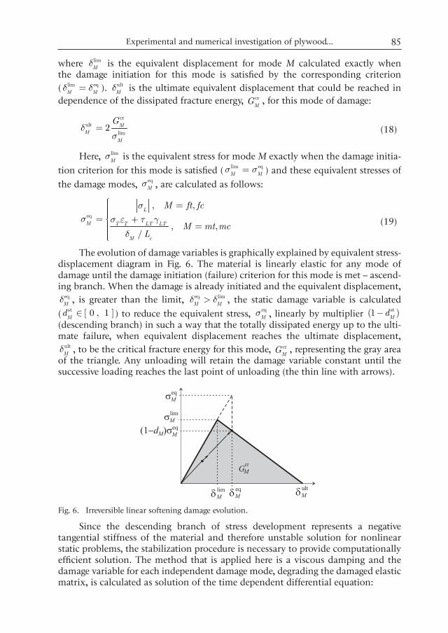
The evolution of damage variables is graphically explained by equivalent stress-displacement diagram in Fig. 6. The material is linearly elastic for any mode of damage until the damage initiation (failure) criterion for this mode is met – ascend-ing branch. When the damage is already initiated and the equivalent displacement,
eqMd , is greater than the limit, eq lim
M Md d> , the static damage variable is calculated
( st [ 0 , 1 ]M
d Î ) to reduce the equivalent stress, eqM
s , linearly by multiplier st(1 )M
d- (descending branch) in such a way that the totally dissipated energy up to the ulti-mate failure, when equivalent displacement reaches the ultimate displacement,
ultMd , to be the critical fracture energy for this mode, cr
MG , representing the gray area
of the triangle. Any unloading will retain the damage variable constant until the successive loading reaches the last point of unloading (the thin line with arrows).
Fig. 6. Irreversible linear softening damage evolution.
Since the descending branch of stress development represents a negative tangential stiffness of the material and therefore unstable solution for nonlinear static problems, the stabilization procedure is necessary to provide computationally efficient solution. The method that is applied here is a viscous damping and the damage variable for each independent damage mode, degrading the damaged elastic matrix, is calculated as solution of the time dependent differential equation:
Ivelin V. Ivanov, Tomasz Sadowski, Magdalena Filipiak, Marcin Kneć86
st1( )
M M MM
d d dh
= - , (20)
where Mh is the viscous coefficient for this mode of damage M.
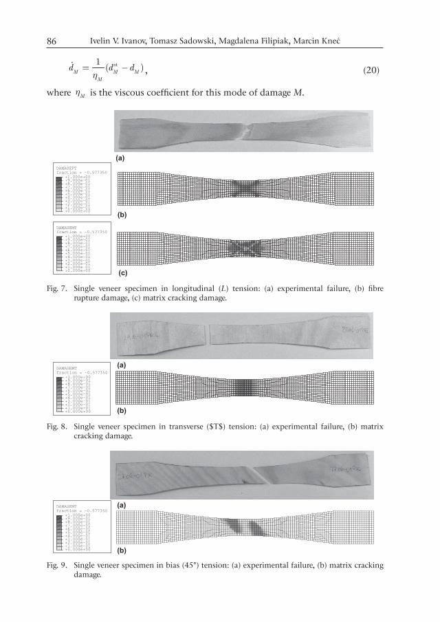
Fig. 7. Single veneer specimen in longitudinal (L) tension: (a) experimental failure, (b) fibre rupture damage, (c) matrix cracking damage.
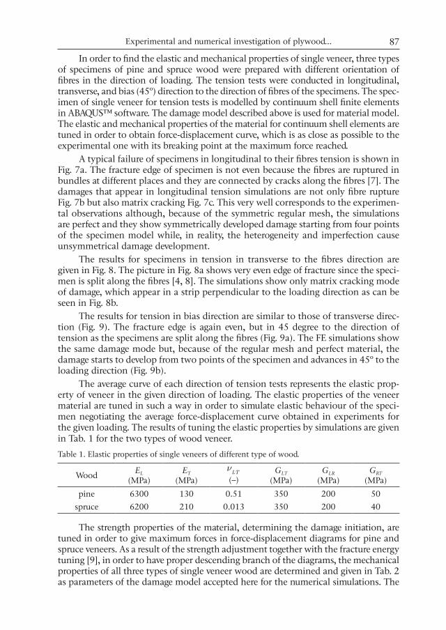
Fig. 8. Single veneer specimen in transverse ($T$) tension: (a) experimental failure, (b) matrix cracking damage.
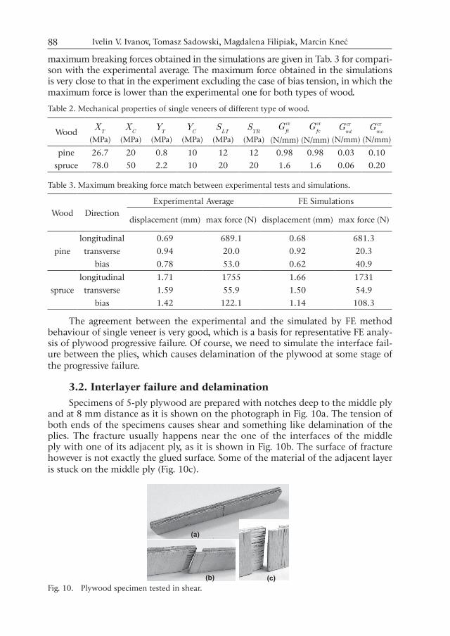
Fig. 9. Single veneer specimen in bias (45°) tension: (a) experimental failure, (b) matrix cracking damage.
Experimental and numerical investigation of plywood... 87
In order to find the elastic and mechanical properties of single veneer, three types of specimens of pine and spruce wood were prepared with different orientation of fibres in the direction of loading. The tension tests were conducted in longitudinal, transverse, and bias (45º) direction to the direction of fibres of the specimens. The spec-imen of single veneer for tension tests is modelled by continuum shell finite elements in ABAQUS™ software. The damage model described above is used for material model. The elastic and mechanical properties of the material for continuum shell elements are tuned in order to obtain force-displacement curve, which is as close as possible to the experimental one with its breaking point at the maximum force reached.
A typical failure of specimens in longitudinal to their fibres tension is shown in Fig. 7a. The fracture edge of specimen is not even because the fibres are ruptured in bundles at different places and they are connected by cracks along the fibres [7]. The damages that appear in longitudinal tension simulations are not only fibre rupture Fig. 7b but also matrix cracking Fig. 7c. This very well corresponds to the experimen-tal observations although, because of the symmetric regular mesh, the simulations are perfect and they show symmetrically developed damage starting from four points of the specimen model while, in reality, the heterogeneity and imperfection cause unsymmetrical damage development.
The results for specimens in tension in transverse to the fibres direction are given in Fig. 8. The picture in Fig. 8a shows very even edge of fracture since the speci-men is split along the fibres [4, 8]. The simulations show only matrix cracking mode of damage, which appear in a strip perpendicular to the loading direction as can be seen in Fig. 8b.
The results for tension in bias direction are similar to those of transverse direc-tion (Fig. 9). The fracture edge is again even, but in 45 degree to the direction of tension as the specimens are split along the fibres (Fig. 9a). The FE simulations show the same damage mode but, because of the regular mesh and perfect material, the damage starts to develop from two points of the specimen and advances in 45º to the loading direction (Fig. 9b).
The average curve of each direction of tension tests represents the elastic prop-erty of veneer in the given direction of loading. The elastic properties of the veneer material are tuned in such a way in order to simulate elastic behaviour of the speci-men negotiating the average force-displacement curve obtained in experiments for the given loading. The results of tuning the elastic properties by simulations are given in Tab. 1 for the two types of wood veneer.
Table 1. Elastic properties of single veneers of different type of wood.
Wood EL
(MPa)ET
(MPa)LT
n(–)
GLT
(MPa)GLR
(MPa)GRT
(MPa)
pine 6300 130 0.51 350 200 50spruce 6200 210 0.013 350 200 40
The strength properties of the material, determining the damage initiation, are tuned in order to give maximum forces in force-displacement diagrams for pine and spruce veneers. As a result of the strength adjustment together with the fracture energy tuning [9], in order to have proper descending branch of the diagrams, the mechanical properties of all three types of single veneer wood are determined and given in Tab. 2 as parameters of the damage model accepted here for the numerical simulations. The
Ivelin V. Ivanov, Tomasz Sadowski, Magdalena Filipiak, Marcin Kneć88
maximum breaking forces obtained in the simulations are given in Tab. 3 for compari-son with the experimental average. The maximum force obtained in the simulations is very close to that in the experiment excluding the case of bias tension, in which the maximum force is lower than the experimental one for both types of wood.
Table 2. Mechanical properties of single veneers of different type of wood.
Wood TX
(MPa)C
X(MPa)
TY
(MPa)C
Y(MPa)
LTS
(MPa)TR
S(MPa)
crft
G(N/mm)
crfc
G(N/mm)
crmt
G(N/mm)
crmc
G(N/mm)
pine 26.7 20 0.8 10 12 12 0.98 0.98 0.03 0.10spruce 78.0 50 2.2 10 20 20 1.6 1.6 0.06 0.20
Table 3. Maximum breaking force match between experimental tests and simulations.
Wood DirectionExperimental Average FE Simulations
displacement (mm) max force (N) displacement (mm) max force (N)
longitudinal 0.69 689.1 0.68 681.3pine transverse 0.94 20.0 0.92 20.3
bias 0.78 53.0 0.62 40.9longitudinal 1.71 1755 1.66 1731
spruce transverse 1.59 55.9 1.50 54.9bias 1.42 122.1 1.14 108.3
The agreement between the experimental and the simulated by FE method behaviour of single veneer is very good, which is a basis for representative FE analy-sis of plywood progressive failure. Of course, we need to simulate the interface fail-ure between the plies, which causes delamination of the plywood at some stage of the progressive failure.
3.2. Interlayer failure and delaminationSpecimens of 5-ply plywood are prepared with notches deep to the middle ply
and at 8 mm distance as it is shown on the photograph in Fig. 10a. The tension of both ends of the specimens causes shear and something like delamination of the plies. The fracture usually happens near the one of the interfaces of the middle ply with one of its adjacent ply, as it is shown in Fig. 10b. The surface of fracture however is not exactly the glued surface. Some of the material of the adjacent layer is stuck on the middle ply (Fig. 10c).
Fig. 10. Plywood specimen tested in shear.
Experimental and numerical investigation of plywood... 89
The results of shear tests are used to set the strength of ply interface [10], which can be simulated in FE model of plywood by cohesive elements. They are very similar to continuum shell elements in their geometry and nodal degrees of free-dom. 3-D elements have three translational degrees of freedom per node and local coordinate system defining the normal of the element and two tangential directions in the plane of the element.
The constitutive response of cohesive elements is determined by traction-sep-aration relationship [5]. The separation in cohesive elements is defined as a rela-tive displacement of upper nodes to lower nodes with respect to their normals with three components: , , ,
ii n s td = in normal direction, n, and in the other
two tangential directions, s and t, respectively. Using the element thickness, h, the constitutive response of damaged element can be defined as:
( )(1 ) i
i c i
KT d
hd= - (no summation on i) (21)
where Ti are the traction components and dc is a damage variable which is initially zero and when the damage initiation criterion is met it could has evolution and could reach unity.
The damage initiation is determined by quadratic nominal stress criterion:
( )
22 2
lim 2lim
n s tc
cc
T T TF
s t
æ ö÷ +ç ÷ç ÷= +ç ÷ç ÷ç ÷çè ø
(22)
when it becomes greater than unity 1c
F ³ ). Here limc
s and limct are the peeling and
shear strengths of the interface while the symbol denotes Macaulay’s brackets.
Effective traction, effT , and effective separation, eff
d , are calculated at the initiation of damage:
2 2 2eff n s t
T T T T= + +
(23)
2 2 2eff n s td d d d= + +
(24)
and they are denoted as limeff
T and limeffd , respectively.
The damage evolution after the damage initiation is governed by linear soften-ing, which can determined the static damage variable, st
cd , by the expression:
ult limst st eff eff eff
ult limeff eff eff
( )max ,
( )c cd d
d d d
d d d
ì üï ï-ï ïï ï= í ýï ï-ï ïï ïî þ (25)
where ult cr limeff eff
2 /c
G Td = is the ultimate effective separation calculated from critical fracture energy of cohesion, cr
cG . The damage evolution in cohesive elements is
very similar to the single veneer damage evolution and it can be illustrated by the diagram in Fig. 6 replacing equivalent displacement and stress by effective separation and traction. The total critical fracture energy is defined by its three components:
Ivelin V. Ivanov, Tomasz Sadowski, Magdalena Filipiak, Marcin Kneć90
cr cr cr crc n s t
G G G G= + + (26)
and in the mix-mode failure at the ultimate state the components of the dissipated energy satisfy the power law criterion:
cr cr cr1n s t
n s t
G G G
G G G
a a aæ ö æ ö æ ö÷ ÷ ÷ç ç ç÷ ÷ ÷ç ç ç+ + =÷ ÷ ÷ç ç ç÷ ÷ ÷ç ç ç÷ ÷ ÷ç ç çè ø è ø è ø
(27)
with parameter 2a = in this case. When the cohesive elements are used to connect continuum shell elements, they are not loaded by peeling traction and the only mode of failure of cohesive elements is shear.
In order to avoid numerical difficulties in FE simulation of cohesive elements failure, viscous damage stabilization is implemented. The viscous damage variable,
cd , degrading the elastic properties of material, is calculated from the static damage variable, st
cd , using the viscous coefficient c
h by the relationship:
st1( )
c c cc
d d dh
= -
(28)
The accepted properties of cohesive elements and their failure parameters are chosen to correspond to the shear strength determined experimentally and to some data found in literature. The properties are given in Tab. 4. The thickness of the cohesive elements used in the FE model of plywood is very small, it is 0.02h = mm. In order to have stable calculation when the cohesive element properties are degraded, viscous stabilization is accepted for cohesive elements with viscous coefficient
0.01ch = s.
Table 4. Properties of cohesive elements modeling the plywood interlayer connection.
nK
(MPa)
sK
(MPa)
tK
(MPa)
limn
s
(MPa)
lims
s
(MPa)
limt
s
(MPa)
crn
G
(N/mm)
crs
G
(N/mm)
crt
G
(N/mm)1910 250 250 20 6.89 6.89 0.6 0.6 0.6
4. CT test simulations and resultsA quarter of plywood CT specimen was modelled by finite elements. Each
veneer ply is modelled by one layer of continuum shell elements. The layers are connected by one interlayer of cohesive elements with 0.02 mm thickness. The plies of veneer have thickness of 1.5 mm and the continuum shell elements account for this thickness by deducting the thickness of cohesive elements from it in order to obey the total thickness of the plywood. The lay-up is set to [pine/spruce/spruce/pine/pine]s.
The loading velocity in the CT test simulations is 1 mm/s and the viscous coef-ficients for stabilization, which are used in the damage model of continuum shell elements as well as in cohesive elements, are all equal to 0.01 s .
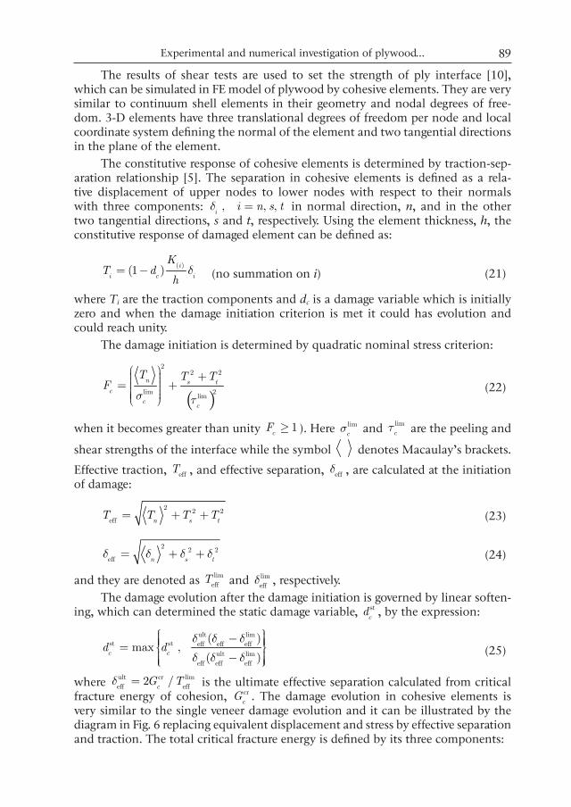
The simulation of longitudinal CT specimens in tension gave force-displace-ment curve, which is given in Fig. 11a in comparison with the experimental ones of three specimens. The maximum breaking force in the simulation is in good agree-ment with the experimental average but the descending branch is not steep enough
Experimental and numerical investigation of plywood... 91
and damages in the simulation are delayed. The simulation of transverse CT speci-mens in tension shows very similar results as force-displacement curve, which is given in Fig. 11b. The force-displacement curve of simulated bias tension is lower than the experimental ones (see Fig. 11c). The maximum breaking forces of single veneer tension in this direction, however, are lower than the experimental averages for both pine and spruce wood and this explains the results.
Fig. 11. Force-displacement diagrams of three specimens compared with the simulation.
Ivelin V. Ivanov, Tomasz Sadowski, Magdalena Filipiak, Marcin Kneć92
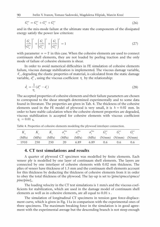
The contour plots shown in Fig. 12 are taken for the same instant of longi-tudinal tension simulation. They present the development of fibre rupture damage in longitudinal plies (Fig. 12a) which advances, except in the stronger spruce wood veneer, followed almost immediately by the matrix cracking of transverse plies (Fig. 12b) and then followed with some delay by the delamination of interlayers (Fig. 12c).
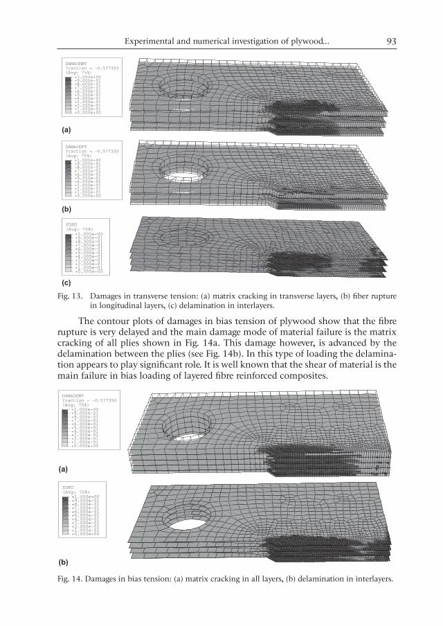
The contour plots shown in Fig. 13 present the development of matrix crack-ing of transverse plies (Fig. 13a) together with fibre rupture damage in longitudinal plies (Fig. 13b), which advances in the weaker pine wood ply and delayed in the stronger veneer. The matrix cracking of transverse plies is like more pronounced here in comparison with the longitudinal sample and the delamination of the inter-layers (Fig. 13c) is again delayed.
Fig. 12. Damages in longitudinal tension: (a) fibre rupture in longitudinal layers, (b) matrix crack-ing in transverse layers, (c) delamination in interlayers.
Experimental and numerical investigation of plywood... 93
Fig. 13. Damages in transverse tension: (a) matrix cracking in transverse layers, (b) fiber rupture in longitudinal layers, (c) delamination in interlayers.
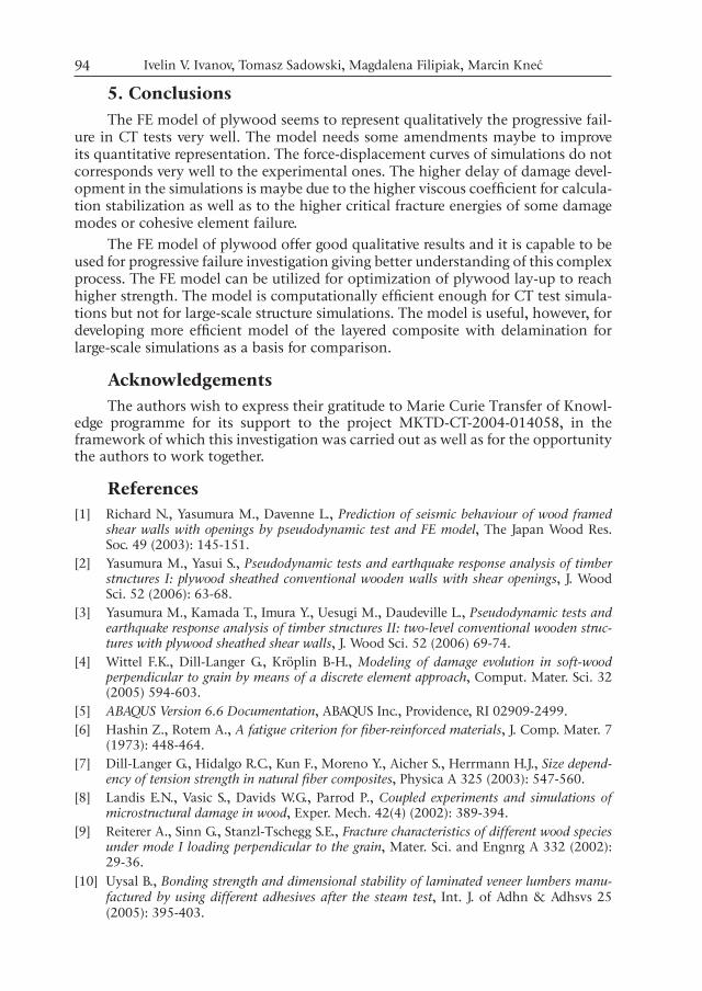
The contour plots of damages in bias tension of plywood show that the fibre rupture is very delayed and the main damage mode of material failure is the matrix cracking of all plies shown in Fig. 14a. This damage however, is advanced by the delamination between the plies (see Fig. 14b). In this type of loading the delamina-tion appears to play significant role. It is well known that the shear of material is the main failure in bias loading of layered fibre reinforced composites.
Fig. 14. Damages in bias tension: (a) matrix cracking in all layers, (b) delamination in interlayers.
Ivelin V. Ivanov, Tomasz Sadowski, Magdalena Filipiak, Marcin Kneć94
5. ConclusionsThe FE model of plywood seems to represent qualitatively the progressive fail-
ure in CT tests very well. The model needs some amendments maybe to improve its quantitative representation. The force-displacement curves of simulations do not corresponds very well to the experimental ones. The higher delay of damage devel-opment in the simulations is maybe due to the higher viscous coefficient for calcula-tion stabilization as well as to the higher critical fracture energies of some damage modes or cohesive element failure.
The FE model of plywood offer good qualitative results and it is capable to be used for progressive failure investigation giving better understanding of this complex process. The FE model can be utilized for optimization of plywood lay-up to reach higher strength. The model is computationally efficient enough for CT test simula-tions but not for large-scale structure simulations. The model is useful, however, for developing more efficient model of the layered composite with delamination for large-scale simulations as a basis for comparison.
AcknowledgementsThe authors wish to express their gratitude to Marie Curie Transfer of Knowl-
edge programme for its support to the project MKTD-CT-2004-014058, in the framework of which this investigation was carried out as well as for the opportunity the authors to work together.
References[1] Richard N., Yasumura M., Davenne L., Prediction of seismic behaviour of wood framed
shear walls with openings by pseudodynamic test and FE model, The Japan Wood Res. Soc. 49 (2003): 145-151.
[2] Yasumura M., Yasui S., Pseudodynamic tests and earthquake response analysis of timber structures I: plywood sheathed conventional wooden walls with shear openings, J. Wood Sci. 52 (2006): 63-68.
[3] Yasumura M., Kamada T., Imura Y., Uesugi M., Daudeville L., Pseudodynamic tests and earthquake response analysis of timber structures II: two-level conventional wooden struc-tures with plywood sheathed shear walls, J. Wood Sci. 52 (2006) 69-74.
[4] Wittel F.K., Dill-Langer G., Kröplin B-H., Modeling of damage evolution in soft-wood perpendicular to grain by means of a discrete element approach, Comput. Mater. Sci. 32 (2005) 594-603.
[5] ABAQUS Version 6.6 Documentation, ABAQUS Inc., Providence, RI 02909-2499.[6] Hashin Z., Rotem A., A fatigue criterion for fiber-reinforced materials, J. Comp. Mater. 7
(1973): 448-464.[7] Dill-Langer G., Hidalgo R.C., Kun F., Moreno Y., Aicher S., Herrmann H.J., Size depend-
ency of tension strength in natural fiber composites, Physica A 325 (2003): 547-560.[8] Landis E.N., Vasic S., Davids W.G., Parrod P., Coupled experiments and simulations of
microstructural damage in wood, Exper. Mech. 42(4) (2002): 389-394.[9] Reiterer A., Sinn G., Stanzl-Tschegg S.E., Fracture characteristics of different wood species
under mode I loading perpendicular to the grain, Mater. Sci. and Engnrg A 332 (2002): 29-36.
[10] Uysal B., Bonding strength and dimensional stability of laminated veneer lumbers manu-factured by using different adhesives after the steam test, Int. J. of Adhn & Adhsvs 25 (2005): 395-403.