Embed Size (px)
Citation preview
Experimental and Modeling Study on Reductionof Hematite Pellets by Hydrogen Gas
MANIA KAZEMI, MOHSEN SAFFARI POUR, and DU SICHEN
Gaseous reduction by hydrogen was performed for three types of hematite pellets, two fromindustry and one prepared in the laboratory. The reduction mechanisms of the pellets werestudied based on the morphologies of the partially reduced samples. Two mechanisms werefound, the mechanisms of the two types of industrial pellets being very similar. The degree ofreduction was followed as a function of time for each type of pellets. On the basis of the reactionmechanism of the industrial pellets, a mathematical model was developed. As a pioneer effort,the model combined the computational fluid dynamics approach for the flow and mass transferin the gas phase with model of gas diffusion in the solid phase as well as the description of thechemical reaction at the reaction sites. The calculation results agreed well with theexperimentally obtained reduction curves. The present work also emphasized the importanceof evaluation of the reduction mechanisms and the properties of different types of iron orepellets prior to developing a process model. While the present approach has established a goodfoundation for the dynamic modeling of the shaft reactor, more efforts are required toaccomplish a realistic process model.
DOI: 10.1007/s11663-016-0895-3� The Author(s) 2017. This article is published with open access at Springerlink.com
I. INTRODUCTION
THE rising interests in application of direct-reducediron (DRI) have given the researchers new challenges inthis area. An important factor in production of DRI inindustrial practice, such as MIDREX or HYL pro-cesses, is the dynamic control of the process in thereactors. This dynamic control along with optimizationof the process is essential to ensure both smooth processoperation and the quality of the products, for examplethe metallization degree and cementite fraction in thereduced pellets. In the counter-current reactors fordirect reduction, the oxide pellets move downward fromthe top of the reactor facing the gas mixture injectedfrom the lower part. The chemical potentials of thegaseous species and the temperature vary at differentpositions in the reactor. The chemical potentials of thespecies can also differ inside each pellet at a givenposition. Hence, an efficient dynamic control of theprocess and the quality of the products demands arealistic process model.
A number of modeling works can be found forreduction of single pellets through different mechanisms,and for multi-particle reduction processes.[1–16] In awork by Bonalde et al., reduction kinetics of iron orepellets were described by the grain model.[1] Pure H2,pure CO, and gas mixtures similar to MIDREX gaswere used. Reduction by pure gases was controlled by a
mixed mechanism in the initial stages and was changedto diffusion controlled mechanism at later stages. Whenthe gas mixtures were applied, reduction was controlledby a mixed mechanism during the whole process. Themodel considered the size of the particles and theporosity of pellets and the results were in good agree-ment with experimental data for reduction by H2. Tienand Turkdogan developed a mathematical model for theisothermal reduction of single iron oxide pellets by asingle-phase reducing gas (H2 or CO).[2] They developeda two-zone and a three-zone model for pellets withdifferent diameters. It was demonstrated that thethree-zone model consisting of a metal layer, metal-oxide layer, and oxide core could describe the reductionof pellets used in direct reduction process. Kineticmodels for gaseous reduction of single pellets withshrinking core or grain model have also been studied byother researchers.[3–6]
The reduction zone of the shaft furnace in MIDREXprocess was simulated by Parisi and Laborde.[7] Theunreacted shrinking core model was applied to thepellets. The process model developed assuming plugflow in the reactor was validated by data from twoindustrial plants and was found useful to predict theeffects of different operation conditions on the process.Ranzani da Costa et al. simulated the reduction in ashaft furnace using hydrogen as the reductant.[8] Theydeveloped and validated a kinetic model for pelletsbased on the laboratory results for reduction of smalloxide particles. By applying the kinetic model in a modelfor a shaft reactor, the metallization degrees and theinfluences of different parameters were predicted. Theyconcluded that the industrial hydrogen-based reductionprocess is feasible. A 2D model for reduction of iron ore
MANIA KAZEMI, MOHSEN SAFFARI POUR, and DUSICHEN are with the Department of Materials Science andEngineering, Royal Institute of Technology, 10044 Stockholm,Sweden. Contact e-mail: [email protected]
Manuscript submitted June 27, 2016.Article published online January 3, 2017.
1114—VOLUME 48B, APRIL 2017 METALLURGICAL AND MATERIALS TRANSACTIONS B

pellets by H2-CO mixtures was developed by Ajbaret al.[9] They applied the shrinking unreacted core modelwith 3 layers and the reduction reactions at theinterfaces were considered reversible. The kinetics ofsteam reforming of methane and carburization were alsoconsidered. The reactor model was developed as a 1Dsteady-state moving bed considering plug flow reactor.They validated the process model by comparison of topgas analysis with the plant data. Shams and Moazennideveloped a mathematical model for the MIDREX shaftfurnace.[10] They applied the shrinking core model to thereduction of pellets and considered the reactions in thereduction zone, transition zone, and cooling zone of theshaft furnace. The majority of the existing processmodels are developed for steady-state conditions; there-fore, the changes occurring during the reduction processand furnace operation are not predictable by thesemodels.
Preliminary studies in the present laboratory indi-cated that the reaction mechanisms could be differentwhen different iron oxide pellets were used. Severalauthors have also reported that variations in the type ofiron oxide pellets, grain size, porosity, and surfacecharacteristics result in different reduction mecha-nisms.[1,17–21] Large variations in the physical andchemical properties of iron ore pellets would limit theapplicability of the existing process models to specifictypes of pellets and experimental conditions. Thus, aprocess model for direct reduction of iron oxide pelletsrequires consideration of the nature of the pellets, thelocal chemical potentials, and the local temperature.
The present work is the first step to develop a dynamicprocess model for direct reduction of iron ore pellets.The present model takes generality into consideration;in other words, it should be applicable to different typesof commercial pellets with possible modifications of thechemical reaction and mass transfer properties accord-ing to the characteristics of the pellets. As the first phaseof model development, the mechanisms of the reductionof 3 types of hematite pellets are studied. This identi-fication is followed by quantifications of the parametersof mass transfer in the two types of industrial pellets. Inthe model, the mass transfer in the gas phase, the masstransfer in the pellet, and the chemical reaction rate areall considered. It is expected that this model can be usedas a sub-model in a model for multi-particle system (e.g.,pellet bed) in the next step.
II. EXPERIMENTAL METHODS
A. Materials Preparation
The reduction experiments were performed for twotypes of industrial iron ore pellets, namely type-I andtype-II, and pure hematite pellets, named type-III. Theaverage diameter of the pellets was between 11 and12 mm. The porosities of type-I and type-II sampleswere 26 and 34 pct, respectively. The hematite content inboth industrial pellets was 96 pct and the pelletscontained small amounts of nonferrous oxides such asSiO2, CaO, and MgO. The type-III samples were
prepared to investigate the reduction of highly densepellets. The pure pellets were made of analytical gradehematite powder and were sintered for 12 hours at1273 K (1000 �C). The porosity of the pure iron oxidepellets was below 20 pct.
B. Experimental Procedure
The experiments were carried out isothermally in thesetup illustrated in Figure 1. The experimental appara-tus and the procedure were described in details in aprevious publication.[21] In each experiment, the samplewas placed in the sample holder and the holder wasconnected to the balance by a stainless steel wire. Afterplacing the sample in the water-cooled chamber, thesetup was completely sealed and flushed with high-pu-rity argon gas. All gas flow rates were controlled bymass flow meters. The reaction chamber was heated upuntil the target temperature was reached in the hot zoneof the reaction tube. During heating, an argon atmo-sphere was maintained. When the temperature wasstable, argon was replaced by hydrogen and the systemwas flushed with hydrogen gas with 2 L min�1 flow ratefor 10 minutes to obtain a homogeneous atmosphere.The reaction was started by lowering the sample to thehot zone of the reaction tube. The movement was ratherfast and took less than 5 seconds. The weight of thesample was recorded during reaction. When the reduc-tion was complete, quenching was performed by liftingthe sample rapidly to the cooling chamber and flushingthe system by Ar gas with high flow rate. To investigatethe reduction mechanism, a few samples were quenchedwhen a certain degree of reaction was reached. The
Fig. 1—Schematic illustration of the experimental setup.
METALLURGICAL AND MATERIALS TRANSACTIONS B VOLUME 48B, APRIL 2017—1115
microstructures of partially and completely reducedsamples were studied by SEM-EDS and LOM.
III. EXPERIMENTAL RESULTSAND DISCUSSION
A. Mechanism of Reduction by Pure H2
Reduction tests were carried out at 1073 K (800 �C)and 1123 K (850 �C). In all experiments, hydrogen gaswith high purity was applied with a constant flow rate,namely 2 L min�1. The reduction mechanisms of threetypes of pellets were investigated by microscopic eval-uation of the partially reduced samples. In the followingpresentation, the degree of reduction, Rex, is defined byEq. [1].
Rex ¼W0 �Wt
W0 �W1½1�
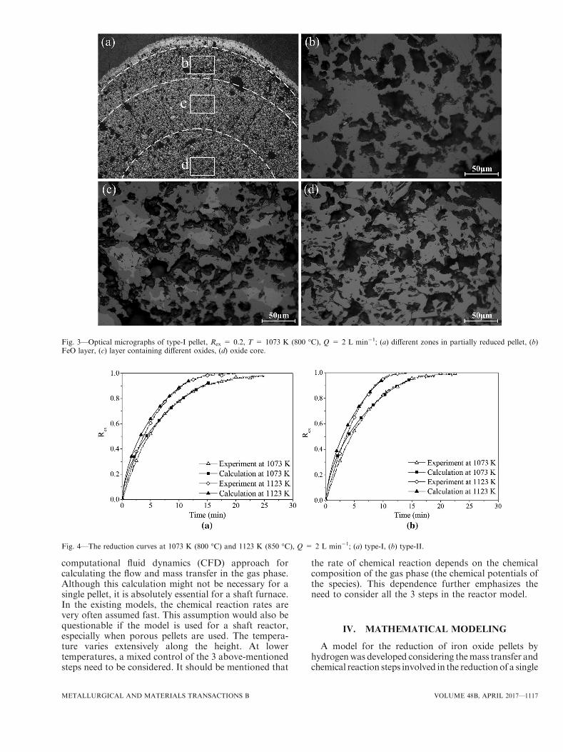
where W0 is the initial weight of the sample, Wt is theweight of pellet at time t, and W¥ is the theoreticalweight after complete reduction. Figure 2 illustratesthe optical micrographs of the samples with partialreduction. Figure 2(a) and (b) shows type-I and type-IIpellets with Rex = 0.2. The micrographs in Figure 3show the different areas in type-I sample reduced at1073 K (800 �C). The thin outer layer around the pel-let is mostly iron, and three different zones areobserved in the inner parts of the sample (Figure 3(b)and (c)). Figure 3b shows the layer consisting of wus-tite. The layer with two different oxide phases is shownin Figure 3(c). The core of the pellet is consisted ofone oxide phase and is shown in Figure 3(d). Theobserved layers containing different phases indicatethat the progress of reaction is being controlled byboth internal gaseous diffusion and chemical reactionin the layers. At identical experimental conditions,reduction of type-II pellets took place with a similarmechanism.
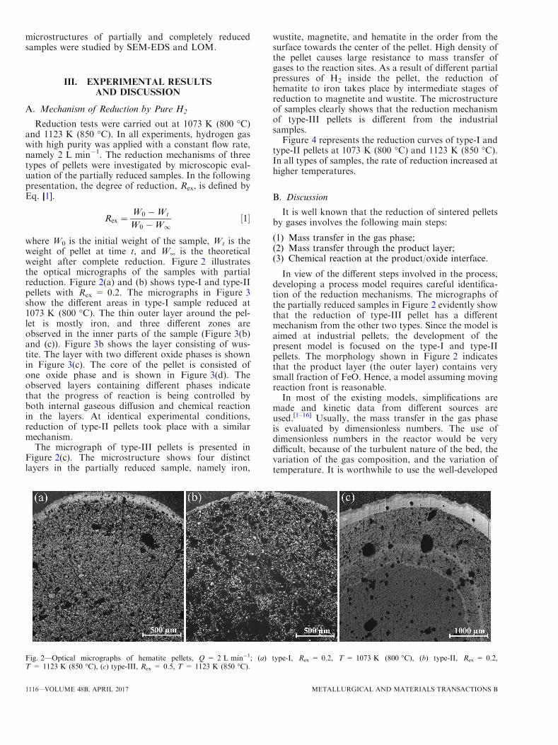
The micrograph of type-III pellets is presented inFigure 2(c). The microstructure shows four distinctlayers in the partially reduced sample, namely iron,
wustite, magnetite, and hematite in the order from thesurface towards the center of the pellet. High density ofthe pellet causes large resistance to mass transfer ofgases to the reaction sites. As a result of different partialpressures of H2 inside the pellet, the reduction ofhematite to iron takes place by intermediate stages ofreduction to magnetite and wustite. The microstructureof samples clearly shows that the reduction mechanismof type-III pellets is different from the industrialsamples.Figure 4 represents the reduction curves of type-I and
type-II pellets at 1073 K (800 �C) and 1123 K (850 �C).In all types of samples, the rate of reduction increased athigher temperatures.
B. Discussion
It is well known that the reduction of sintered pelletsby gases involves the following main steps:
(1) Mass transfer in the gas phase;(2) Mass transfer through the product layer;(3) Chemical reaction at the product/oxide interface.
In view of the different steps involved in the process,developing a process model requires careful identifica-tion of the reduction mechanisms. The micrographs ofthe partially reduced samples in Figure 2 evidently showthat the reduction of type-III pellet has a differentmechanism from the other two types. Since the model isaimed at industrial pellets, the development of thepresent model is focused on the type-I and type-IIpellets. The morphology shown in Figure 2 indicatesthat the product layer (the outer layer) contains verysmall fraction of FeO. Hence, a model assuming movingreaction front is reasonable.In most of the existing models, simplifications are
made and kinetic data from different sources areused.[1–16] Usually, the mass transfer in the gas phaseis evaluated by dimensionless numbers. The use ofdimensionless numbers in the reactor would be verydifficult, because of the turbulent nature of the bed, thevariation of the gas composition, and the variation oftemperature. It is worthwhile to use the well-developed
Fig. 2—Optical micrographs of hematite pellets, Q = 2 L min�1; (a) type-I, Rex = 0.2, T = 1073 K (800 �C), (b) type-II, Rex = 0.2,T = 1123 K (850 �C), (c) type-III, Rex = 0.5, T = 1123 K (850 �C).
1116—VOLUME 48B, APRIL 2017 METALLURGICAL AND MATERIALS TRANSACTIONS B
computational fluid dynamics (CFD) approach forcalculating the flow and mass transfer in the gas phase.Although this calculation might not be necessary for asingle pellet, it is absolutely essential for a shaft furnace.In the existing models, the chemical reaction rates arevery often assumed fast. This assumption would also bequestionable if the model is used for a shaft reactor,especially when porous pellets are used. The tempera-ture varies extensively along the height. At lowertemperatures, a mixed control of the 3 above-mentionedsteps need to be considered. It should be mentioned that
the rate of chemical reaction depends on the chemicalcomposition of the gas phase (the chemical potentials ofthe species). This dependence further emphasizes theneed to consider all the 3 steps in the reactor model.
IV. MATHEMATICAL MODELING
A model for the reduction of iron oxide pellets byhydrogenwas developed considering themass transfer andchemical reaction steps involved in the reduction of a single
Fig. 3—Optical micrographs of type-I pellet, Rex = 0.2, T = 1073 K (800 �C), Q = 2 L min�1; (a) different zones in partially reduced pellet, (b)FeO layer, (c) layer containing different oxides, (d) oxide core.
Fig. 4—The reduction curves at 1073 K (800 �C) and 1123 K (850 �C), Q = 2 L min�1; (a) type-I, (b) type-II.
METALLURGICAL AND MATERIALS TRANSACTIONS B VOLUME 48B, APRIL 2017—1117

pellet. The 2D axisymmetric model was developed inCOMSOLMultiphysics 5.1 software.[22] This model couldbe later applied in amulti-particle processmodel to predictthe atmosphere composition in the furnace and themetallization degree of theDRIunder different conditions.
As mentioned above, considering the importance ofthe industrial iron ore pellets, the model was based onthe mechanism observed in the type-I and type-IIsamples. The following assumptions were made:
1. The temperature is constant in the model and is equalto the reduction temperature.
2. The density of the gas is constant.3. The porosity of the solid and the effective diffusivity
do not change with time.4. The chemical reaction takes place isothermally and it
is expressed by Eq. [2].
1
3Fe2O3 þH2 !
2
3FeþH2O ½2�
5. The presence of small amounts of oxide in the outerlayer is neglected and the layer is approximated aspure iron.
A. The Model Domains
The model domains are illustrated in Figure 5. Themodel consists of solid and gaseous phases.
The gas phase consists of H2 and produced H2O. Theflow in the gas phase is governed by the equations ofcontinuity and conservation of momentum (Eq. [3]through [5]).
[23]
Continuity equation
@q@t
þ 1
r
@
@rqrvrð Þ þ @
@zqvzð Þ ¼ 0: ½3�
Momentum equationsr-component:
q@vr@t
þ vr@vr@r
þ vz@vr@z
� �¼ � @P
@r� 1
r
@
@rrsrrð Þ þ @srz
@z
� �:
½4�
z-component:
q@vz@t
þ vr@vz@r
þ vz@vz@z
� �¼ � @P
@z� 1
r
@
@rrsrzð Þ þ @szz
@z
� �:
½5�In the gas phase, mass transfer due to convection and
diffusion are considered and the mass transfer isgoverned by the mass balance equation (Eq. [6]).[23]
@c
@tþ vr
@C
@rþ vz
@C
@z
� �¼ D
1
r
@
@rr@C
@r
� �þ @2C
@z2
� �: ½6�
The solid phases refer to the product layer and theunreduced core in the pellet. The mass transfer of gasesin the solid is described by the diffusive fluxes of H2 andH2O shown in Eqs. [7] and [8].
NH2¼ �ADeff;H2
dCH2
dr½7�
NH2O ¼ �ADeff;H2OdCH2O
dr: ½8�
In Eqs. [7] and [8], A is the reaction surface area. It isevaluated at every calculation step using the location ofthe moving boundary (the inner radius). Due to theporous nature of the solid phases, the effective diffusioncoefficients of gases in the solids was applied in themodel. The effective diffusivity, Deff, is defined byEq. [9].[23]
Deff ¼ DAxs; ½9�
where DA is the diffusivity of gas A; x is the porosityof solid, and s is the tortuosity factor which is deter-mined by the structure of the solid. The porosity andtortuosity factor are specific characteristics of eachtype of pellet and are independent of the gas proper-ties. For a given gas mixture, the effective diffusivitychanges with the temperature and with the type ofpellet.
B. Boundary Conditions
The gas has normal inflow velocity at the inlet wherethe volumetric flow rate of hydrogen is equal to2 L min�1. At the gas outlet, the pressure is set to
Fig. 5—The calculation domains: 1 reaction tube, 2 gas inlet, 3 pel-let, 4 reacting layer, 5 oxide core, and 6 gas outlet.
1118—VOLUME 48B, APRIL 2017 METALLURGICAL AND MATERIALS TRANSACTIONS B
atmospheric pressure. In the computational domains,no-slip boundary condition is considered for all walls.The temperature in the system is the reactiontemperature.
The flux of hydrogen from the gas phase to the pellet,and the flux of produced water vapor from the pelletsurface to the gas phase are the boundary conditions atthe pellet-gas interface which connect the mass transferbetween the solid and the gas stream. The walls of thereaction tube were considered as boundaries with nomass fluxes. The apparent rates of chemical reactionwere obtained from an unpublished work by the presentresearch group.[24] In this study, 20 mg of fine iron orepowder (a few lm in particle size) was kept in a veryshallow crucible in a hydrogen stream of high flow rate.This arrangement would ensure that the reaction wascontrolled by chemical reaction at least at the initialstage of the reaction. The rates were estimated from the
largest slope of reduction curves. The estimated valuesare presented in Table I.The size and the shape of the meshes in the calculation
domains were carefully selected due to the complexity ofthe connection between the moving boundary in thesolid and the exchange of fluxes between gas and solidphases. Therefore, the MUMPS solver in COMSOLMultiphysics was used in the fully coupled calculations.Three meshes were tested for the calculations as listed inTable II. Mesh M2 was chosen for all calculationsbecause it provided similar precision for the calculatedreaction extents as the finer mesh, within a moreappropriate solution time. An initial value of Deff foreach sample was evaluated from the experimental resultfor reaction extent at 20 minutes, considering thereduction at this stage is mostly controlled by masstransfer of gases in the solid phase. Based on this initialvalue, the Deff was optimized by the model using curve
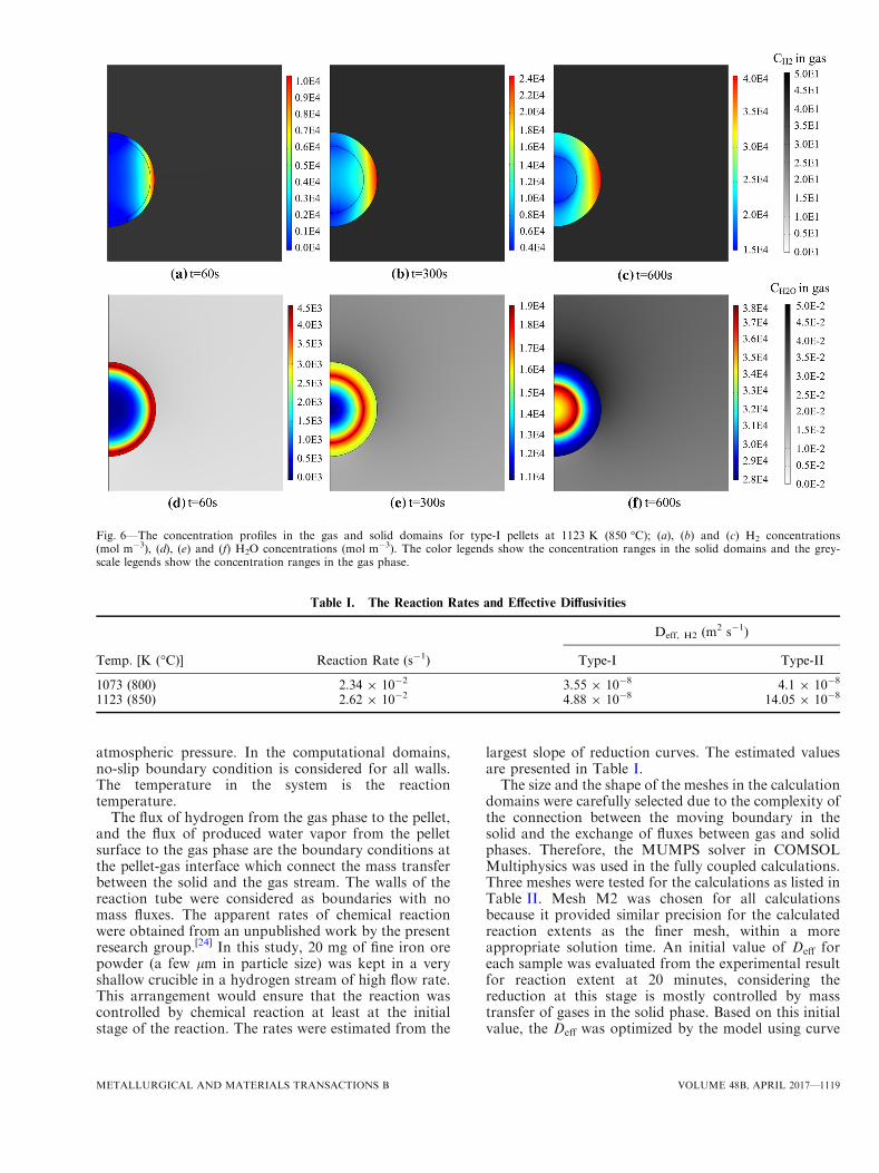
Fig. 6—The concentration profiles in the gas and solid domains for type-I pellets at 1123 K (850 �C); (a), (b) and (c) H2 concentrations(mol m�3), (d), (e) and (f) H2O concentrations (mol m�3). The color legends show the concentration ranges in the solid domains and the grey-scale legends show the concentration ranges in the gas phase.
Table I. The Reaction Rates and Effective Diffusivities
Temp. [K (�C)] Reaction Rate (s�1)
Deff, H2 (m2 s�1)
Type-I Type-II
1073 (800) 2.34 9 10�2 3.55 9 10�8 4.1 9 10�8
1123 (850) 2.62 9 10�2 4.88 9 10�8 14.05 9 10�8
METALLURGICAL AND MATERIALS TRANSACTIONS B VOLUME 48B, APRIL 2017—1119

fitting. The Deff values (reported in the table) are themass transfer properties associated with different pellets.
V. CALCULATION RESULTS AND DISCUSSION
Figure 6 presents the concentration distributions ofH2 and H2O in the solid and gas domains, calculated fortype-I pellets at 1123 K (850 �C). The results show thatthe H2O produced at the reaction site diffuses into theunreacted core. Note that in most studies using shrink-ing core model, the presence of H2O in the oxide phase isnot considered. The presence of H2O in the oxide phaseaffects the local equilibrium between solids and gasesand influences the reduction rate.
The stream lines around the pellet are laminar, andthe gas velocities are nearly constant with respect to timein the fluid domain, except the zone very near the gasinlet in the lower part of reaction tube. In fact, the gasvelocity is nearly uniform in the whole reaction tube,showing that even in the area above the pellet nostagnant zone is formed. However, at low gas flow rates,it can be expected that significantly low velocities insome areas affect the distribution of gaseous species andtherefore influence the equilibrium. Thus, it is essentialto consider this factor in a larger scale process modeldue to more complex fluid flow in the reactor.
The concentration distributions of H2 and H2O in thesolid and the surrounding gas phase are presented inFigure 6 at three different time intervals. The figure indi-cates that the concentration of hydrogen in the gasphase does not vary with time. The changes in H2Oconcentration in the gas phase are also rather small. Itshould be pointed out that when a single pellet isreacting in a gas stream with high concentration of H2,the concentration of H2O in the surrounding gas phaseis low. However, in the larger scale processes, theamounts of gaseous products are larger and have agreater impact on the atmosphere. In addition, the gascomposition varies at different heights of the shaftfurnace. The concentration profiles of the reactants andproducts in Figure 6 highlight the importance of con-necting the mass transfers in the gas phase and the solidphase to obtain reliable results for the concentrationchanges of all species during the process. It should bementioned that H2O is produced from the chemicalreaction taking place at the reaction interface with anaxisymmetric rate, and therefore, the distribution ofH2O is axisymmetric. Hydrogen is provided with highflow rate from the gas inlet placed in the bottom of thereaction tube. Therefore, the H2 flow in the gas phasehas a large effect on hydrogen distribution in the solid.Although H2 is consumed in the pellet with an axisym-metric chemical reaction rate, the distribution of H2 isnot axisymmetric during reduction.
The optimized Deff values for hydrogen in the twotypes of commercial pellets at the experimental temper-atures are listed in Table I. Using the values in Table I,the degrees of reaction are calculated for type-I andtype-II pellets by the model. The calculated Rex areplotted as a function of time in Figure 4 to comparewith the experimental results. It is seen that the
calculation results are in general in good agreementwith the experimental data. The plots in Figure 4illustrate that while the calculations predict the reactionextents of type-I and type-II pellets reasonably well,there are still some differences between the experimentalreaction extents and the calculations. At the initialstages, the reduction rate is slightly higher in thecalculated curves. The difference is slightly more in thecase of type-II samples. The differences could be causedby assuming that the reaction takes place at theboundary of the unreacted core. On the other hand, aspresented in Figure 3, the chemical reaction takes placein a layer. This aspect needs to be considered in furtherimprovements of the model. Nevertheless, the presentmodel could be a good basis for the development of acomprehensive process model.In order to examine the role of chemical reaction in
the process, a calculation was made for type-I pelletassuming the reaction was fast, so that the reactionalways reached equilibrium. Figure 7 shows the com-parison of the results from this calculation with theexperimental data. The poor model prediction suggeststhat chemical reaction plays an important role almost inthe whole process of reduction for the pellets havinghigh porosity. This argument is supported by themorphology of the partially reduced sample shown inFigure 3(c). It is clearly seen that in the reaction zone,different oxides coexist. Neglecting the role of chemicalreaction in the process model might lead to unsatisfac-tory results. Figures 4 and 7 indicate that couplingchemical reaction with diffusion and mass transfer in themodel is necessary for process modeling.Similar calculation procedure was applied to predict
the reduction curve for type-III sample at 1123 K(850 �C). Note that, many efforts were made to obtain
Fig. 7—The influence of reaction rate on the calculation results at1123 K (850 �C) for type-I pellets.
Table II. Comparison of Different Meshes
Mesh M1 M2 M3
Total number of elements 113084 61028 33508Rex at t = 600 s 0.896 0.886 0.871
1120—VOLUME 48B, APRIL 2017 METALLURGICAL AND MATERIALS TRANSACTIONS B
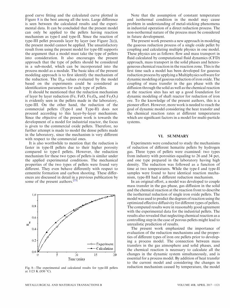
good curve fitting and the calculated curve plotted inFigure 8 is the best among all the tests. Large differenceis seen between the calculated results and the experi-mental data. It can be concluded that the present modelcan only be applied to the pellets having reactionmechanism as type-I and type-II. Since the reaction oftype-III pellet proceeds layer by layer (see Figure 2(c)),the present model cannot be applied. The unsatisfactoryresult from using the present model for type-III supportsthe argument that a model must take the type of pelletsinto consideration. It also encourages the presentapproach that the type of pellets should be consideredin a sub-model, which can be incorporated into theprocess model as a module. The basic idea of the presentmodeling approach is to first identify the mechanism ofthe reduction. The Deff values evaluated by the modelbased on the experiments could be considered asidentification parameters for each type of pellets.
It should be mentioned that the reduction mechanismof layer by layer reduction (Fe, FeO, Fe3O4, and Fe2O3)is evidently seen in the pellets made in the laboratory,type-III. On the other hand, the reduction of thecommercial pellets (Type-I and Type-II) does notproceed according to this layer-by-layer mechanism.Since the objective of the present work is towards thedevelopment of a model for industrial reactor, the focusis given to the commercial oxide pellets. Therefore, nofurther attempt is made to model the dense pellets madein the laboratory, since the mechanism is very differentwith respect to the commercial ones.
It is also worthwhile to mention that the reduction isfaster in type-II pellets due to their higher porositycompared to type-I pellets. However, the reductionmechanism for these two types of pellets is similar underthe applied experimental conditions. The mechanicalproperties of the two types of pellets were found verydifferent. They even behave differently with respect tocementite formation and carbon shooting. These differ-ences are discussed in detail in a previous publication bysome of the present authors.[25]
Note that the assumption of constant temperatureand isothermal condition in the model may causeproblem in understanding of metal-sticking phenomenain industrial operation of a direct reduction process. Thenon-isothermal nature of the process must be consideredin future development.The present work presents a new approach inmodeling
the gaseous reduction process of a single oxide pellet bycoupling and calculating multiple physics in one model.These physics are as follows: flow and mass transport influid calculated by computational fluid dynamics (CFD)approach, mass transport in the solid phases and hetero-geneous chemical reaction in the reaction zone. This is thefirst time such a model has been developed for gaseousreduction process by applying aMultiphysics software fordynamicmodeling of gaseous reductionof ironoxide. Thecoupling of mass transfer in the gas phase with thediffusion through the solid aswell as the chemical reactionat the reaction sites has set up a good foundation fordynamic modeling of shaft reactor for reduction of ironore. To the knowledge of the present authors, this is apioneer effort.However,more work is needed to reach thegoal of dynamic model considering the heat transfer andthe chemical reaction rates at different temperatureswhich are significant factors in a model for multi-particlesystems.
VI. SUMMARY
Experiments were conducted to study the mechanismsof reduction of different hematite pellets by hydrogengas. Three types of pellets were examined: two typesfrom industry with porosities equaling to 26 and 34 pct,and one type prepared in the laboratory having highdensity. The reduction was followed as a function oftime at two temperatures. While the type-I and type-IIsamples were found to have identical reaction mecha-nism, type-III had a different reduction mechanism.In an original effort, a model was developed to couple
mass transfer in the gas phase, gas diffusion in the solidand the chemical reaction at the reaction front to describethe isothermal reduction of single iron oxide pellets. Themodelwas used to predict the degrees of reactionusing theoptimized effective diffusivity for different types of pellets.The computed results were in reasonably good agreementwith the experimental data for the industrial pellets. Theresults also revealed that neglecting chemical reaction as acontrolling step in the case of porous pellets might lead tounrealistic prediction of results.The present work emphasized the importance of
evaluation of the reduction mechanisms and the proper-ties of different types of iron ore pellets prior to develop-ing a process model. The connection between masstransfers in the gas atmosphere and solid phases, andthe chemical reaction is necessary to calculate all thechanges in the dynamic system simultaneously, and isessential for a process model. By addition of heat transferto the current model and considering the changes inreduction mechanism caused by temperature, the modelFig. 8—The experimental and calculated results for type-III pellets
at 1123 K (850 �C).
METALLURGICAL AND MATERIALS TRANSACTIONS B VOLUME 48B, APRIL 2017—1121
can be applied as a sub-model in a multi-particle processwith varying temperature profile and atmosphere.
ACKNOWLEDGMENTS
The authors would like to thank Magnus Tottie andLars Norrman for the invaluable discussions, sugges-tions, and comments. The financial support fromLKAB is gratefully acknowledged.
OPEN ACCESS
This article is distributed under the terms of theCreative Commons Attribution 4.0 InternationalLicense (http://creativecommons.org/licenses/by/4.0/),which permits unrestricted use, distribution, and re-production in any medium, provided you give appro-priate credit to the original author(s) and the source,provide a link to the Creative Commons license, andindicate if changes were made.
REFERENCES
1. A Bonalde A Henriquez M Manrique : ISIJ Int., 2005, vol. 45,pp. 1255–60.
2. RH Tien and ET Turkdogan: Metall. Trans., 1972, vol. 3,pp. 2039–48.
3. QT Tsay, WH Ray, and J Szekely: AIChe J., 1976, vol. 22,pp. 1064–72.
4. J Bessieres, A Bessieres, and JJ Heizmann: Int. J. Hydrog. Energy,1980, vol. 5, pp. 585–95.
5. K Piotrowski, K Mondal, H Lorethova, L Stonawski,T Szymanski, and T Wiltowski: Int. J. Hydrog. Energy, 2005,vol. 30, pp. 1543–54.
6. A Pineau, N Kanari, and I Gaballah: Thermochim. Acta, 2006,vol. 447, pp. 89–100.
7. DRParisi andMALaborde:Chem.Eng. J., 2004, vol. 104, pp. 35–43.8. A Ranzani da Costa, D Wagner, and F Patisson: J. Cleaner Prod.,
2013, vol. 46, pp. 27–35.9. A Ajbar, K Alhumaizi, and M Soliman: Ironmak. Steelmak., 2011,
vol. 38, pp. 401–11.10. A. Shams and F. Moazeni, JOM, 2015, pp. 2681-89.11. KO Yu and PP Gillis: Metall. Trans. B, 1981, vol. 12, pp. 111–20.12. Y Takenaka and Y Kimura: Comput. Chem. Eng., 1986, vol. 10,
pp. 67–75.13. ED Negri, OM Alfano, and MG Chiovetta: Ind. Eng. Chem. Res.,
1991, vol. 30, pp. 474–82.14. ED Negri, OM Alfano, and MG Chiovetta: Ind. Eng. Chem. Res.,
1995, vol. 34, pp. 4266–76.15. MS Valipour, MY Motamed Hashemi, and Y Saboohi: Adv.
Powder Technol., 2006, vol. 17, pp. 277–95.16. SMM Nouri, H Ale Ebrahim E Jamshidi: Chem. Eng. J., 2011,
vol. 166, pp. 704–9.17. MVC Sastri, RP Viswanath, and B Viswanathan: Int. J. Hydrog.
Energy, 1982, vol. 7, pp. 951–55.18. RJ Fruehan, Y Li, L Brabie, and E-J Kim: Scand. J. Metall., 2005,
vol. 34, pp. 205–12.19. ET Turkdogan and JV Vinters: Metall. Trans., 1971, vol. 2,
pp. 3175–88.20. D. Wagner, O. Devisme, F. Patisson, and D. Ablitzer: Sohn
International Symposium on Advanced Processing of Metals andMaterials, 2006, vol. 2, pp. 111–20.
21. M Kazemi, B Glaser, and D Sichen: Steel Res. Int., 2014, vol. 85,pp. 718–28.
22. COMSOL Multiphysics� v. 5.1. www.comsol.com. COMSOLAB, Stockholm, Sweden.
23. DR Poirier and GH Geiger: Transport Phenomena in MaterialsProcessing, The Minerals, Metals and Materials Society, War-rendale, Pennsylvania, 1994.
24. M. Kazemi: KTH (Royal Institute of Technology), Stockholm,Sweden, 2016.
25. M Kazemi and Du Sichen: Metall. and Materials Trans. B, 2016,DOI:10.1007/s11663-016-0780-0.
1122—VOLUME 48B, APRIL 2017 METALLURGICAL AND MATERIALS TRANSACTIONS B