Embed Size (px)
Citation preview
Experimental and Analytical Performance Investigation of Air to
Air Two Phase Closed Thermosyphon based Heat Exchangers
J. Danielewicz1, M. A. Sayegh1, B. Śniechowska1, M. Szulgowska-Zgrzywa1, H. Jouhara2*
1Institute of Air Conditioning and District Heating, Faculty of Environmental Engineering ,Wrocław
University of Technology, ul. C.K.Norwida 4/6, 50-373 Wrocław - Poland, Email: [email protected]
2 RCUK Centre for Sustainable Energy Use in Food Chains, Brunel University, Uxbridge, Middlesex, UB8 3PH, UK, Email: [email protected]
Submitted to
Energy
* Corresponding Author
ABSTRACT In recent years, the use of wickless heat pipes (thermosyphons) in heat exchangers has been on the rise, particularly in gas to gas heat recovery applications due to their reliability and the level of contingency they offer compared to conventional heat exchangers. Recent technological advances in the manufacturing processes and production of gravity assisted heat pipes (thermosyphons) have resulted in significant improvements in both quality and cost of industrial heat pipe heat exchangers. This in turn has broadened the potential for their usage in industrial waste heat recovery applications. In this paper, a tool to predict the performance of an air to air thermosyphon based heat exchanger using the ε-NTU method is explored. This tool allows the predetermination of variables such as the overall heat transfer coefficient, effectiveness, pressure drop and heat exchanger duty according to the flow characteristics and the thermosyphons configuration within the heat exchanger. The new tool’s predictions were validated experimentally and a good correlation between the theoretical predictions and the experimental data, was observed.
Keywords: Heat recovery, Heat pipes, Thermosyphons, Effectiveness, Pressure drop
1. INTRODUCTION Over the past 20 years, climate change has established itself as the greatest driving force for innovation in the industry for the first time in over two centuries [1-5]. This fact has forced engineers and designers to go for more sustainable and efficient energy systems designs in built environment [6] and process industries [7;8]. In the 21st century, every corporation must be aware of the environmental damage it may cause through its actions; actions, which may come in many interchangeable forms, namely waste [9;10], radiation [11], greenhouse gases [1] and/or heat [12-15]. With regards to heat energy, when released from a hot exhaust, it can be reutilised and/or recycled by heat exchangers [16-18] for re-use within industrial processes or for district heating of neighbouring communities.
Heat exchangers are devices that, as the name states, are able to extract heat from where it is unwanted and transfer it to where it may be usefully applied [19-21]. They can be found essentially everywhere in modern industry due to current environmental policies [22], adopting different shapes depending on their application including the thermosyphon based designs [15;23], which is the topic of this paper.
Heat transfer within a thermosyphon heat exchanger, instead of being done through a solid boundary, is facilitated through the use of two phase closed thermosyphons. A thermosyphon consists of a hermetically sealed evacuated tube partially filled with a working fluid. The working fluid enters a permanent state of evaporation-condensation the moment there is a temperature difference between the top and the bottom sections of the pipe. A high amount of heat can be transferred through the phase change processes that are constantly taking place within the thermosyphon during the working fluid evaporation/condensation cycles. This characteristic is the key to these devices’ high effective thermal conductivity, allowing them to have an equivalent thermal conductivity of one to two orders of magnitude higher than that of copper [15].
The working cycle of a thermosyphon (Figure 1) starts when heat is added to the evaporator section (bottom). The working fluid readily absorbs the heat and evaporates, travelling to the condenser section (top) in a gaseous form. By making contact with the cold wall of the tube in the condenser section, the working fluid condenses, transferring all the energy it had absorbed to the wall and flowing back down to the evaporator section, thus repeating the cycle. In wickless heat pipes, it is essential for the condenser section to be located above the evaporator section, hence the alternative name “gravity-assisted heat pipes”. Heat pipes can also be equipped with a wick structure, having the advantage of being able to transfer heat even when turned upside-down, as the condensate is returned to the evaporator via capillary action forces [15]. Heat pipes have been tested and proven in the thermal management of electronics and in the space industry [24;25], in heat storage systems [23;26;27], in renewable energy [28;29] and in waste heat recovery [30-32].
When equipping heat exchangers, thermosyphons are often preferred to heat pipes especially due to the reduction in costs coming from the absence of a wick structure [32]. The advantages of thermosyphon heat exchangers over conventional heat exchangers include a good flow separation, no additional power input to the system, high reliability [12;17;33;34], lower initial investment and operating costs [16;35], the ability to work at lower temperature differences [35] and a contingency plan – if a pipe or number of pipes were to fail, the heat exchanger would remain operational [16;20]. Their application is not limited to waste heat recovery in the industrial domain; in fact, heat pipe technology utilisation has spread to ventilation and air conditioning [13;16;21;33;36-38], solar collectors [39] and even water desalination systems [20].
Air to air cross-flow thermosyphon based heat exchangers have been of interest to many researchers. It can be seen from the literature that there are many methods available to gauge the performance of these devices [12;13;16;18;40]. In this paper, the 𝜀𝜀-NTU (Effectiveness-Number of Transfer Units) method is used to develop a prediction tool of the thermal performance of a thermosyphon based air to air heat exchanger. Using this method, Jouhara and Merchant [16] have investigated a thermosyphon heat exchanger with respect to its inclination and it was found that this type of heat exchanger performed better as it became closer to the vertical inclination. Noie [18] also used the 𝜀𝜀-NTU method and arrived at the same conclusion; but he also found that the minimum effectiveness for a heat exchanger with this specific geometry is encountered when the heat capacity is the same for both hot and cold flows; if the flows consist of the same gas, the minimum effectiveness will be found when the mass flow rates are equal. It was also found that the accuracy of prediction methods increased with increasing the inlet velocity. In other studies, different working fluids [40] and different filling ratios [41] have been experimentally studied in similar heat exchangers as well as different sets of variables, such as electrohydrodynamics (EHD) [42]. In addition, similar investigations for such systems were also reported for solar collectors’ applications [39].
In this paper, the 𝜀𝜀-NTU method is used to measure the performance of the heat exchanger and to predict the temperatures and flow conditions between the rows of thermosyphons within the heat exchanger. A computational model is then created, based on the experimental work, with the purpose of predicting the performance of the cross-flow thermosyphon-equipped gas-to-gas heat exchanger with reliable accuracy. It is believed that the reported modelling approach of thermosyphon based air to air heat exchangers will provide a straightforward and useful tool to engineers and researchers working in this area to help them designing such systems.
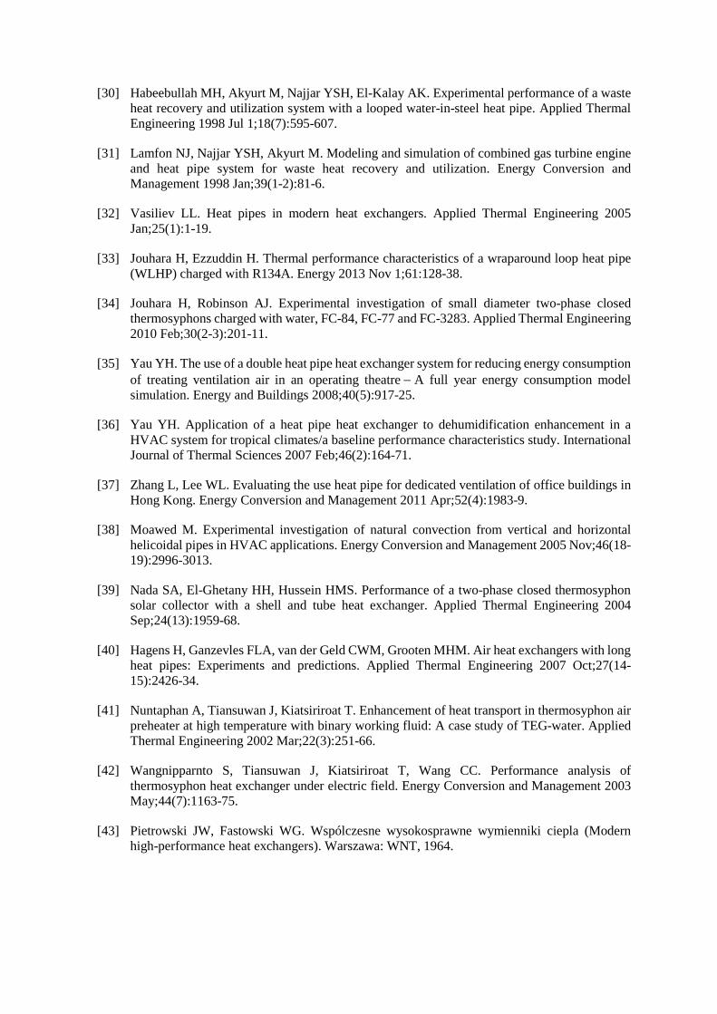
2. TEST FACILITY DESIGN Figure 2 shows a photo and a schematic of the tested heat exchanger. The characteristics of the heat exchanger were studied experimentally in order to validate the heat transfer ε-NTU based model that will, besides allowing the determination of the overall heat transfer coefficient and effectiveness, enable the prediction of the air stream temperature between any two thermosyphon rows. In order to gather the necessary data, different test parameters were experimented upon where the hot and cold air streams velocities varied from 0.3 m/s to 0.5 m/s with mass flow rates of up to 1 kg/s. The hot air temperature varied up to 120 °C while the cold air stream temperature varied up to 30 °C.
As can be seen in Figure 3, the inlet air flows were driven by fans, which were connected in series and powered by electric motors. The fan’s speed was adjusted in order to control the hot and cold inlet air mass flow rates. The air blown across the fan would then be forced through the air filter and cooled to the required temperature by travelling through the water temperature control framework. After passing through the flow straightening fitting, the cold air was directed to a nozzle and then to the condenser section of the thermosyphon heat exchanger.
After being heated in the condenser, the air would then flow through the water heater in order to help preheat the incoming air to the evaporator to the desired inlet temperature. The heated air would then flow through the straightening fitting and through the nozzle, and then would be allowed to pass through the evaporator section of the heat exchanger. An additional measuring outlet was provided, which

served to further measure the mass flow rate of the air after passing through the heat exchanger, allowing an estimation of the potential air leakage from one stream to another within the tested parameters.
The static and dynamic pressures were measured at specific points before and after the heat exchanger using micro manometers (pressure sensors), allowing the identification of pressure drops in the streams. In order to adjust the mass flow rate, air dampers were additionally installed. The air temperatures before and after the heat exchanger were measured with thermocouples, while the air temperatures in the ducts were measured using k-type thermocouples. The joints of welded thermocouples were placed in special brass tubes that were used to slow down the hot air flow at the measurement point. The ducts were divided into nine parts, and a thermocouple was placed in the middle of each section for additional monitoring of the temperature before and after the heat exchanger.
The air flow rate was measured at the nozzles and at the outlet by utilising the data from the pressure sensors. The nozzles had narrowing diameters d2 = 310.0 mm and d1 = 170.5 mm. The polynomials for nozzle control were the following:
Nozzle 400/253: ℎ = 0.360 × 10⁻¹⁶ Re3 + 0.202 × 10⁻¹⁰ Re2 − 0.375 × 10⁻⁵ Re + 0.882
Nozzle 500/273: ℎ = 0.787 × 10⁻¹⁶ Re3 + 0.386 × 10⁻¹⁰ Re2 − 0.611 × 10⁻⁵ Re + 0.938
The flow velocity was altered in order to increase the turbulence and therefore the heat transfer rate. The output of the measuring nozzles was manipulated in order to offer desirable Reynolds numbers.
3. TEST PIECE DESIGN The heat exchanger under investigation was a vertical cross-flow gas-to-gas thermosyphon heat exchanger as illustrated in Figure 2. A total of 100 thermosyphons were used, arranged in ten rows with ten thermosyphons per row. Carbon steel was selected as the shell material and methanol as the working fluid. Each thermosyphon had a length of 2200.0 mm, an outer diameter dout = 27.0 mm and a tube wall thickness of 3.5 mm. The fins were made of aluminium, had an outer diameter of dfin = 59.0 mm, a thickness of 0.5 mm and a pitch of 3.0 mm. The lengths of the condensation and evaporation zones in the heat exchanger were the same (l = 1000 mm). The adiabatic section was located between the evaporator and the condenser sections, measuring 200mm.
In order to effectively analyse the heat recovery capabilities of the thermosyphon heat exchanger in each row, a computer program was developed. The performance analysis of the studied heat exchanger was done with the following parameters as input data:
• Dimensions of the rig • Number of tubes per row • Number of rows per section • Air mass flow rates • Inlet temperatures • Working fluid • Characteristics of the fins
The computer program also predicted the following parameters:
• Effectiveness of the heat exchanger • Recovered thermal power • Pressure drop across the heat exchanger in the evaporation and condensation zones • Temperature between each row of the heat exchanger • Pipe surface temperatures throughout the heat exchanger
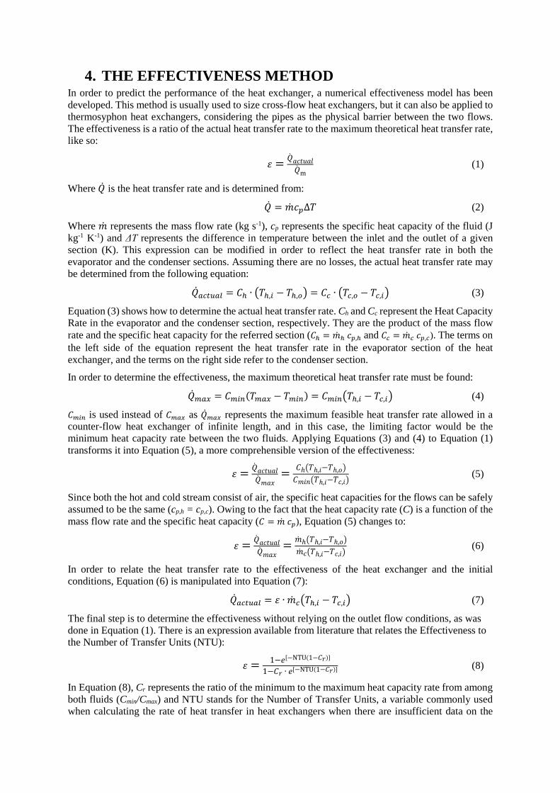
4. THE EFFECTIVENESS METHOD In order to predict the performance of the heat exchanger, a numerical effectiveness model has been developed. This method is usually used to size cross-flow heat exchangers, but it can also be applied to thermosyphon heat exchangers, considering the pipes as the physical barrier between the two flows. The effectiveness is a ratio of the actual heat transfer rate to the maximum theoretical heat transfer rate, like so:
𝜀𝜀 = �̇�𝑄𝑎𝑎𝑎𝑎𝑎𝑎𝑎𝑎𝑎𝑎𝑎𝑎�̇�𝑄m
(1)
Where �̇�𝑄 is the heat transfer rate and is determined from:
�̇�𝑄 = �̇�𝑚𝑎𝑎𝑝𝑝∆𝑇𝑇 (2)
Where �̇�𝑚 represents the mass flow rate (kg s-1), cp represents the specific heat capacity of the fluid (J kg-1 K-1) and ΔT represents the difference in temperature between the inlet and the outlet of a given section (K). This expression can be modified in order to reflect the heat transfer rate in both the evaporator and the condenser sections. Assuming there are no losses, the actual heat transfer rate may be determined from the following equation:
�̇�𝑄𝑎𝑎𝑎𝑎𝑎𝑎𝑎𝑎𝑎𝑎𝑎𝑎 = 𝐶𝐶ℎ ∙ �𝑇𝑇ℎ,𝑖𝑖 − 𝑇𝑇ℎ,𝑜𝑜� = 𝐶𝐶𝑎𝑎 ∙ �𝑇𝑇𝑎𝑎,𝑜𝑜 − 𝑇𝑇𝑎𝑎,𝑖𝑖� (3)
Equation (3) shows how to determine the actual heat transfer rate. Ch and Cc represent the Heat Capacity Rate in the evaporator and the condenser section, respectively. They are the product of the mass flow rate and the specific heat capacity for the referred section (𝐶𝐶ℎ = �̇�𝑚ℎ 𝑎𝑎𝑝𝑝,ℎ and 𝐶𝐶𝑎𝑎 = �̇�𝑚𝑎𝑎 𝑎𝑎𝑝𝑝,𝑎𝑎). The terms on the left side of the equation represent the heat transfer rate in the evaporator section of the heat exchanger, and the terms on the right side refer to the condenser section.
In order to determine the effectiveness, the maximum theoretical heat transfer rate must be found:
�̇�𝑄𝑚𝑚𝑎𝑎𝑚𝑚 = 𝐶𝐶𝑚𝑚𝑖𝑖𝑚𝑚(𝑇𝑇𝑚𝑚𝑎𝑎𝑚𝑚 − 𝑇𝑇𝑚𝑚𝑖𝑖𝑚𝑚) = 𝐶𝐶𝑚𝑚𝑖𝑖𝑚𝑚�𝑇𝑇ℎ,𝑖𝑖 − 𝑇𝑇𝑎𝑎,𝑖𝑖� (4)
𝐶𝐶𝑚𝑚𝑖𝑖𝑚𝑚 is used instead of 𝐶𝐶𝑚𝑚𝑎𝑎𝑚𝑚 as �̇�𝑄𝑚𝑚𝑎𝑎𝑚𝑚 represents the maximum feasible heat transfer rate allowed in a counter-flow heat exchanger of infinite length, and in this case, the limiting factor would be the minimum heat capacity rate between the two fluids. Applying Equations (3) and (4) to Equation (1) transforms it into Equation (5), a more comprehensible version of the effectiveness:
𝜀𝜀 = �̇�𝑄𝑎𝑎𝑎𝑎𝑎𝑎𝑎𝑎𝑎𝑎𝑎𝑎�̇�𝑄𝑚𝑚𝑎𝑎𝑚𝑚
= 𝐶𝐶ℎ�𝑇𝑇ℎ,𝑖𝑖−𝑇𝑇ℎ,𝑜𝑜�𝐶𝐶𝑚𝑚𝑖𝑖𝑚𝑚�𝑇𝑇ℎ,𝑖𝑖−𝑇𝑇𝑎𝑎,𝑖𝑖�
(5)
Since both the hot and cold stream consist of air, the specific heat capacities for the flows can be safely assumed to be the same (cp,h = cp,c). Owing to the fact that the heat capacity rate (C) is a function of the mass flow rate and the specific heat capacity (𝐶𝐶 = �̇�𝑚 𝑎𝑎𝑝𝑝), Equation (5) changes to:
𝜀𝜀 = �̇�𝑄𝑎𝑎𝑎𝑎𝑎𝑎𝑎𝑎𝑎𝑎𝑎𝑎�̇�𝑄𝑚𝑚𝑎𝑎𝑚𝑚
= �̇�𝑚ℎ�𝑇𝑇ℎ,𝑖𝑖−𝑇𝑇ℎ,𝑜𝑜��̇�𝑚𝑎𝑎�𝑇𝑇ℎ,𝑖𝑖−𝑇𝑇𝑎𝑎,𝑖𝑖�
(6)
In order to relate the heat transfer rate to the effectiveness of the heat exchanger and the initial conditions, Equation (6) is manipulated into Equation (7):
�̇�𝑄𝑎𝑎𝑎𝑎𝑎𝑎𝑎𝑎𝑎𝑎𝑎𝑎 = 𝜀𝜀 ∙ �̇�𝑚𝑎𝑎�𝑇𝑇ℎ,𝑖𝑖 − 𝑇𝑇𝑎𝑎,𝑖𝑖� (7)
The final step is to determine the effectiveness without relying on the outlet flow conditions, as was done in Equation (1). There is an expression available from literature that relates the Effectiveness to the Number of Transfer Units (NTU):
𝜀𝜀 = 1−𝑒𝑒[−NTU(1−𝐶𝐶𝑟𝑟)]
1−𝐶𝐶𝑟𝑟 ∙ 𝑒𝑒[−NTU(1−𝐶𝐶𝑟𝑟)] (8)
In Equation (8), Cr represents the ratio of the minimum to the maximum heat capacity rate from among both fluids (Cmin/Cmax) and NTU stands for the Number of Transfer Units, a variable commonly used when calculating the rate of heat transfer in heat exchangers when there are insufficient data on the
outlet conditions. The NTU is determined through Equation (9); it is directly related to U, the overall heat transfer coefficient (W m-2 K-1), A, the heat transfer surface area (m2) and inversely proportional to Cmin, the minimum heat capacity rate:
NTU = 𝑈𝑈∙𝐴𝐴𝐶𝐶𝑚𝑚𝑖𝑖𝑚𝑚
(9)
Going back to Equation (8); as mentioned before, both flows consist of the same fluid, air, which allows for further simplification. It is assumed that the specific capacity rates are the same for both sections (𝑎𝑎𝑝𝑝,ℎ = 𝑎𝑎𝑝𝑝,𝑎𝑎) so it follows that the ratios between the mass flow rates and the heat capacity rates are equal:
𝐶𝐶𝑟𝑟 = 𝐶𝐶𝑚𝑚𝑖𝑖𝑚𝑚𝐶𝐶𝑚𝑚𝑎𝑎𝑚𝑚
, 𝐶𝐶𝑟𝑟 = �̇�𝑚𝑚𝑚𝑖𝑖𝑚𝑚 𝑎𝑎𝑝𝑝�̇�𝑚𝑚𝑚𝑎𝑎𝑚𝑚 𝑎𝑎𝑝𝑝
so 𝐶𝐶𝑟𝑟 = �̇�𝑚𝑚𝑚𝑖𝑖𝑚𝑚�̇�𝑚𝑚𝑚𝑎𝑎𝑚𝑚
= �̇�𝑚𝑟𝑟 (10)
This allows for the simplification of Equation (8) into the following expression:
𝜀𝜀 = 1−𝑒𝑒−𝑁𝑁𝑇𝑇𝑈𝑈(1−�̇�𝑚𝑟𝑟)
1−�̇�𝑚𝑟𝑟 ∙ 𝑒𝑒−𝑁𝑁𝑇𝑇𝑈𝑈(1−�̇�𝑚𝑟𝑟) (11)
In addition to the specific capacity rates, if the mass flow rates of the two flows happen to coincide (Ch = Cc), then the effectiveness can be directly related to the number of transfer units (NTU) through the simple equation:
𝜀𝜀 = NTUNTU+1 (12)
5. RESULTS AND DISCUSSION Before each experiment, an isothermal test was conducted to check the value of the pressure drop within each section of the heat exchanger, as is displayed in Figure 4. The trend line for this figure is an exponential line. To determine the pressure drop in the air flow through the finned tubes, the relationship given by Pietrowski et al. [43] is modified in order to take into account the increase in the number of rows of thermosyphons. The modification consists of replacing the values of the coefficients from 1.35 to 0.95 and by doing so, the equation is transformed into:
𝐸𝐸𝑎𝑎 = 0.95 ∙ (ℎ 𝑑𝑑⁄ )0.45 ∙ (𝑎𝑎 𝑑𝑑⁄ )−0.72 ∙ 𝑅𝑅𝑒𝑒𝑝𝑝−0.24 ∙ 𝑚𝑚
Where h is the fin height, d is the pipe diameter, u is the clearance between fins (all in metres), Re is the Reynolds number and n is the number of rows of tubes in the heat exchanger.
After the isothermal tests, the mass flow rate in the evaporator was kept at 1 m/s and 120 °C and the cold air mass flow rate at 0.25 kg/s and as low temperature as possible. After steady-state was reached, the mass flow rate on the cold side was increased by 0.25 kg/s and the test repeated until testing the 1 kg/s mass flow rate. After that was done, the temperature on the hot side was reduced to 60 °C and the same range of tests was conducted.
Figure 5 shows the correlation between the heat exchanger effectiveness and the average velocity of the air in the condensation section. The effectiveness of the heat exchanger is a ratio of the current heat flow to the maximum theoretical heat flow. A trend line was extrapolated from the data and the results were all situated within 10% of the value ηth = – 0.122 v + 0.685. The effectiveness of the heat exchanger used in the test bench varied from 0.3 to 0.7 and was found to decrease with an increase in the mass flow rate for inlet air. The dispersion seen in the figure was the result of the variation in ratios of mass flow rates between the streams of hot and cold air.
Figure 6 illustrates the effectiveness of the heat exchanger between each row of tubes. It was found that there was a difference of less than 2% in the effectiveness for the different inlet temperatures in the evaporator section (60 °C and 120 °C). The effectiveness of the heat exchanger increased as the flow progressed through the rows, but decreased with increasing mass flow rate on the cold side. It can also be seen in Figure 6 that as the number of rows increases, the curve begins to level out, becoming almost parallel. What can be concluded from it is that there are an optimum number of rows for maximising effectiveness, after which increasing the size of the heat exchanger becomes less economical.
The fact that higher mass flow rates result in a lower effectiveness leads to the conclusion that there is not enough exposure of the pipes to the cold flow, resulting in the flow not getting enough time to absorb the thermal energy being released by the pipes.
The recovered heat, however, increased (as to be expected) linearly with the number of rows of thermosyphons in the heat exchanger, see in Figure 7. This is logical taking into account that each pipe is a very efficient heat exchanger in itself.
All of the above results were included in the computer model and compared to the experimental results. The Nusselt number for both cases can be seen in Figure 8, where good agreement is found. The range of Nusselt numbers presented was extracted from all the conducted experimental tests.
6. CONCLUSIONS The effects of the variation of condenser and evaporator inlet mass flow rates on the performance of an air to air thermosyphon based heat exchanger were investigated experimentally. The experimental results were used to validate the reported numerical tool that was developed through the 𝜀𝜀-NTU method. As it has been demonstrated, the developed tool can be used to predict all the needed variables that are required for the characterisation of a typical cross-flow thermosyphon gas-to-gas heat exchanger, namely the heat transfer coefficient, effectiveness, pressure drop and heat extraction duty. It was found that the heat recovery rate increased as the flow progressed through the heat exchanger. Furthermore, the effectiveness increased as the ratio between both mass flow rates increased, which is in agreement with previous reported works [16;18]. The developed computational model can be used by engineers and researchers in order to design thermosyphon heat exchangers for air to air applications.
ACKNOWLEDGEMENTS Special thanks are due to Mr. Joao Ramos, Mr. Michael Jones, Mr. Mark Boocock and Mr Andrew Holgate for their help.
NOMENCLATURE A (m2) Heat transfer surface area cp (J kg-1 K-1) Specific heat capacity C (J K-1) Heat capacity Rate (�̇�𝑚cp) Cr Ratio of Heat Capacity Rates (Cmin/Cmax) D (mm) Diameter l (m) Length �̇�𝑚 (kg s-1) Mass Flow Rate 𝑚𝑚𝑟𝑟̇ (kg s-1) Ratio of Mass Flow Rates (�̇�𝑚min/�̇�𝑚max) �̇�𝑄 (W) Heat Transfer rate �̇�𝑄max (W) Maximum Theoretical Heat Transfer Rate R (K W-1) Thermal Resistance T (°C or K) Temperature ΔT (°C or K) Difference in Temperature T (mm) Thickness U (W m-2 K-1) Overall heat transfer coefficient 𝜀𝜀 Effectiveness
Subscripts
A Air
c Condenser side / Cold side Fin Fins (for finned tube) h Evaporator Side / Hot side Hp Heat pipe / Thermosyphon I Inlet max Maximum min Minimum n Number of Pipes o Outlet r Ratio
Abbreviations
NTU Number of Transfer Units
REFERENCES [1] Kyoto Protocol, United Nations, (1997).
[2] Olabi AG. State of the art on renewable and sustainable energy. Energy 2013 Nov 1;61(0):2-5.
[3] Climate Change Act . 2008. 7-8-2013.
[4] Olabi AG. Developments in sustainable energy and environmental protection. Energy 2012 Mar;39(1):2-5.
[5] Olabi AG. The 3rd international conference on sustainable energy and environmental protection SEEP 2009 Guest Editor Introduction. Energy 2010 Dec;35(12):4508-9.
[6] Tymkow P, Tassou S, Kolokotroni M, Jouhara H. Building Services Design for Energy Efficient Buildings. Routledge, Spon Press, Taylor & Francis Group, 2013.
[7] Carton JG, Olabi AG. Wind/hydrogen hybrid systems: Opportunity for Ireland wind resource to provide consistent sustainable energy supply. Energy 2010 Dec;35(12):4536-44.
[8] Olabi AG. Developments in sustainable energy and environmental protection. Simulation Modelling Practice and Theory 2011 Apr;19(4):1139-42.
[9] Kosseva MR. Chapter 1 - Recent European Legislation on Management of Wastes in the Food Industry. In: Kosseva MR, Webb C, editors. Food Industry Wastes.San Diego, Academic Press, 2013: p. 3-15.
[10] van den Hove S, Le Menestrel M, de Bettignies HC. The oil industry and climate change: strategies and ethical dilemmas. Climate Policy 2002 May;2(1):3-18.
[11] Berejka AJ, Cleland MR, Walo M. The evolution of and challenges for industrial radiation processing - 2012. Radiation Physics and Chemistry 2014 Jan;94:141-6.
[12] Jouhara H, Meskimmon R. Experimental investigation of wraparound loop heat pipe heat exchanger used in energy efficient air handling units. Energy 2010 Dec;35(12):4592-9.
[13] Jouhara H. Economic assessment of the benefits of wraparound heat pipes in ventilation processes for hot and humid climates. International Journal of Low Carbon Technology 2009;4(1):52-60.
[14] Kerrigan K, Jouhara H, O'Donnell GE, Robinson AJ. Heat pipe-based radiator for low grade geothermal energy conversion in domestic space heating. Simulation Modelling Practice and Theory 2011 Apr;19(4):1154-63.
[15] Reay D, Kew P. Heat Pipes: Theory, Design and Applications. 5 ed. Elsevier Science, 2006.
[16] Jouhara H, Merchant H. Experimental investigation of a thermosyphon based heat exchanger used in energy efficient air handling units. Energy 2012 Mar;39(1):82-9.
[17] Noie SH. Heat transfer characteristics of a two-phase closed thermosyphon. Applied Thermal Engineering 2005 Mar;25(4):495-506.
[18] Noie SH. Investigation of thermal performance of an air-to-air thermosyphon heat exchanger using e-NTU method. Applied Thermal Engineering 2006 Apr;26(5−6):559-67.
[19] Laubscher R, Dobson RT. Theoretical and experimental modelling of a heat pipe heat exchanger for high temperature nuclear reactor technology. Applied Thermal Engineering 2013 Nov 3;61(2):259-67.
[20] Jouhara H, Anastasov V, Khamis I. Potential of heat pipe technology in nuclear seawater desalination. Desalination 2009 Dec 25;249(3):1055-61.
[21] Kerrigan K, Jouhara H, OΓÇÖDonnell GE, Robinson AJ. A naturally aspirated convector for domestic heating application with low water temperature sources. Energy and Buildings 2013 Dec;67(0):187-94.
[22] PEUBE JL, HEWITT GF, EcKERT ERG, et al. WORKING GROUP C - HEAT TRANSFER AND THERMAL ENERGY TRANSPORT. In: KOVACH EG, editor. Thermal Energy Storage. Pergamon, 2013: p. 35-48.
[23] Shabgard H, Bergman TL, Sharifi N, Faghri A. High temperature latent heat thermal energy storage using heat pipes. International Journal of Heat and Mass Transfer 2010 Jul;53(15-16):2979-88.
[24] Savage CJ, ROYAL AIRCRAFT ESTABLISHMENT FARNBOROUGH (England). Heatpipes and Vapour Chambers for Satellite Thermal Balance. Defense Technical Information Center, 1969.
[25] Swanson TD, Birur GC. NASA thermal control technologies for robotic spacecraft. Applied Thermal Engineering 2003 Jun;23(9):1055-65.
[26] Caruso A, Grakovich LP, Pasquetti R, Vasiliev LL. Heat pipe heat storage performance. Heat Recovery Systems and CHP 1989;9(5):407-10.
[27] Nithyanandam K, Pitchumani R. Computational studies on a latent thermal energy storage system with integral heat pipes for concentrating solar power. Applied Energy 2013 Mar;103:400-15.
[28] Chaudhry HN, Hughes BR, Ghani SA. A review of heat pipe systems for heat recovery and renewable energy applications. Renewable and Sustainable Energy Reviews 2012 May;16(4):2249-59.
[29] Akbarzadeh A, Johnson P, Nguyen T, et al. Formulation and analysis of the heat pipe turbine for production of power from renewable sources. Applied Thermal Engineering 2001 Oct;21(15):1551-63.
[30] Habeebullah MH, Akyurt M, Najjar YSH, El-Kalay AK. Experimental performance of a waste heat recovery and utilization system with a looped water-in-steel heat pipe. Applied Thermal Engineering 1998 Jul 1;18(7):595-607.
[31] Lamfon NJ, Najjar YSH, Akyurt M. Modeling and simulation of combined gas turbine engine and heat pipe system for waste heat recovery and utilization. Energy Conversion and Management 1998 Jan;39(1-2):81-6.
[32] Vasiliev LL. Heat pipes in modern heat exchangers. Applied Thermal Engineering 2005 Jan;25(1):1-19.
[33] Jouhara H, Ezzuddin H. Thermal performance characteristics of a wraparound loop heat pipe (WLHP) charged with R134A. Energy 2013 Nov 1;61:128-38.
[34] Jouhara H, Robinson AJ. Experimental investigation of small diameter two-phase closed thermosyphons charged with water, FC-84, FC-77 and FC-3283. Applied Thermal Engineering 2010 Feb;30(2-3):201-11.
[35] Yau YH. The use of a double heat pipe heat exchanger system for reducing energy consumption of treating ventilation air in an operating theatre − A full year energy consumption model simulation. Energy and Buildings 2008;40(5):917-25.
[36] Yau YH. Application of a heat pipe heat exchanger to dehumidification enhancement in a HVAC system for tropical climates/a baseline performance characteristics study. International Journal of Thermal Sciences 2007 Feb;46(2):164-71.
[37] Zhang L, Lee WL. Evaluating the use heat pipe for dedicated ventilation of office buildings in Hong Kong. Energy Conversion and Management 2011 Apr;52(4):1983-9.
[38] Moawed M. Experimental investigation of natural convection from vertical and horizontal helicoidal pipes in HVAC applications. Energy Conversion and Management 2005 Nov;46(18-19):2996-3013.
[39] Nada SA, El-Ghetany HH, Hussein HMS. Performance of a two-phase closed thermosyphon solar collector with a shell and tube heat exchanger. Applied Thermal Engineering 2004 Sep;24(13):1959-68.
[40] Hagens H, Ganzevles FLA, van der Geld CWM, Grooten MHM. Air heat exchangers with long heat pipes: Experiments and predictions. Applied Thermal Engineering 2007 Oct;27(14-15):2426-34.
[41] Nuntaphan A, Tiansuwan J, Kiatsiriroat T. Enhancement of heat transport in thermosyphon air preheater at high temperature with binary working fluid: A case study of TEG-water. Applied Thermal Engineering 2002 Mar;22(3):251-66.
[42] Wangnipparnto S, Tiansuwan J, Kiatsiriroat T, Wang CC. Performance analysis of thermosyphon heat exchanger under electric field. Energy Conversion and Management 2003 May;44(7):1163-75.
[43] Pietrowski JW, Fastowski WG. Wspólczesne wysokosprawne wymienniki ciepla (Modern high-performance heat exchangers). Warszawa: WNT, 1964.

Fig.1. The thermosyphon’s working cycle
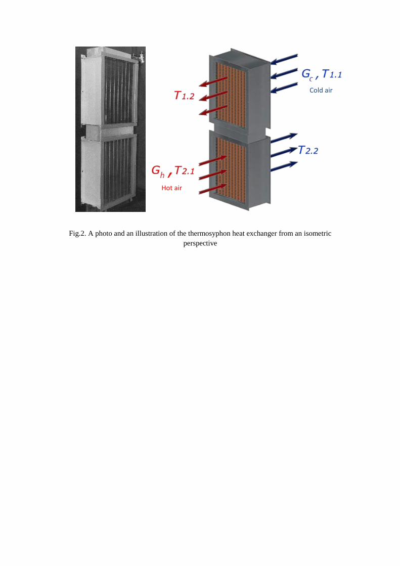
Fig.2. A photo and an illustration of the thermosyphon heat exchanger from an isometric perspective
Hot air
Cold air
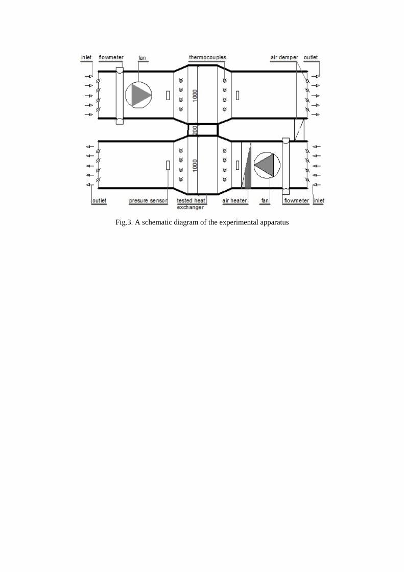
Fig.3. A schematic diagram of the experimental apparatus
Fig. 4. Pressure drop of the heat exchanger as function of the inlet air velocity (hot side data)
10
100
1000
0.1 1 10
Pres
sure
Dro
p (P
a)
Velocity of Inlet Air (m/s)
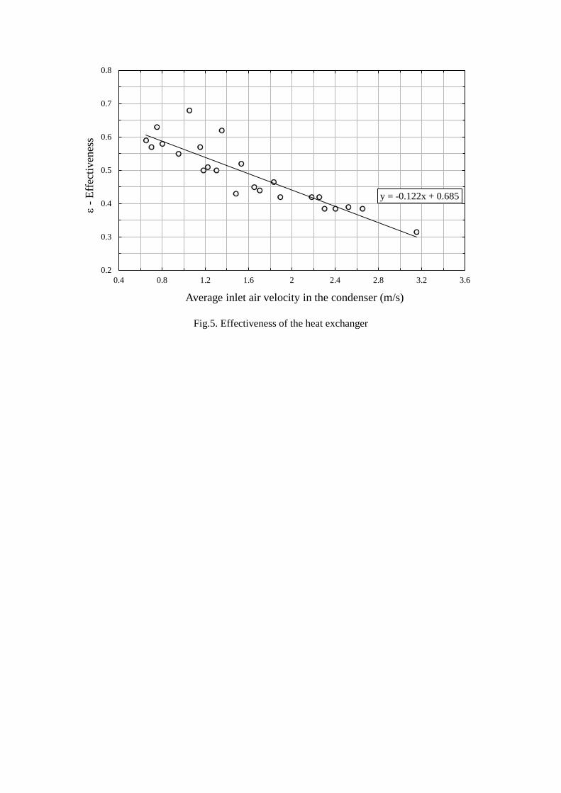
Fig.5. Effectiveness of the heat exchanger
y = -0.122x + 0.685
0.2
0.3
0.4
0.5
0.6
0.7
0.8
0.4 0.8 1.2 1.6 2 2.4 2.8 3.2 3.6
ε-E
ffect
iven
ess
Average inlet air velocity in the condenser (m/s)
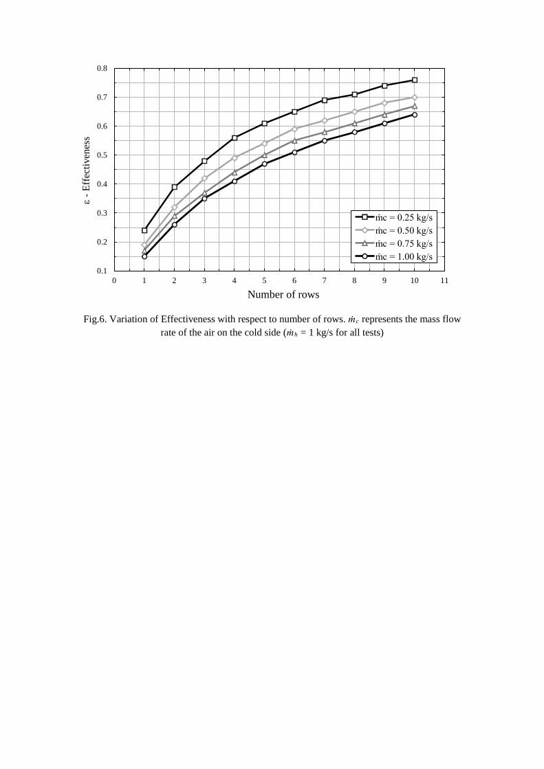
Fig.6. Variation of Effectiveness with respect to number of rows. ṁc represents the mass flow rate of the air on the cold side (ṁh = 1 kg/s for all tests)
0.1
0.2
0.3
0.4
0.5
0.6
0.7
0.8
0 1 2 3 4 5 6 7 8 9 10 11
ε-E
ffec
tiven
ess
Number of rows
ṁc = 0.25 kg/sṁc = 0.50 kg/sṁc = 0.75 kg/sṁc = 1.00 kg/s
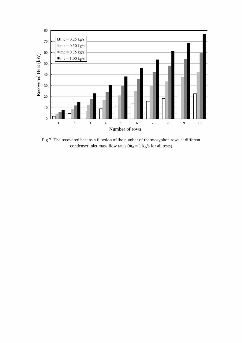
Fig.7. The recovered heat as a function of the number of thermosyphon rows at different condenser inlet mass flow rates (ṁh = 1 kg/s for all tests)
0
10
20
30
40
50
60
70
80
1 2 3 4 5 6 7 8 9 10
Rec
over
ed H
eat(
kW)
Number of rows
ṁc = 0.25 kg/sṁc = 0.50 kg/sṁc = 0.75 kg/sṁc = 1.00 kg/s
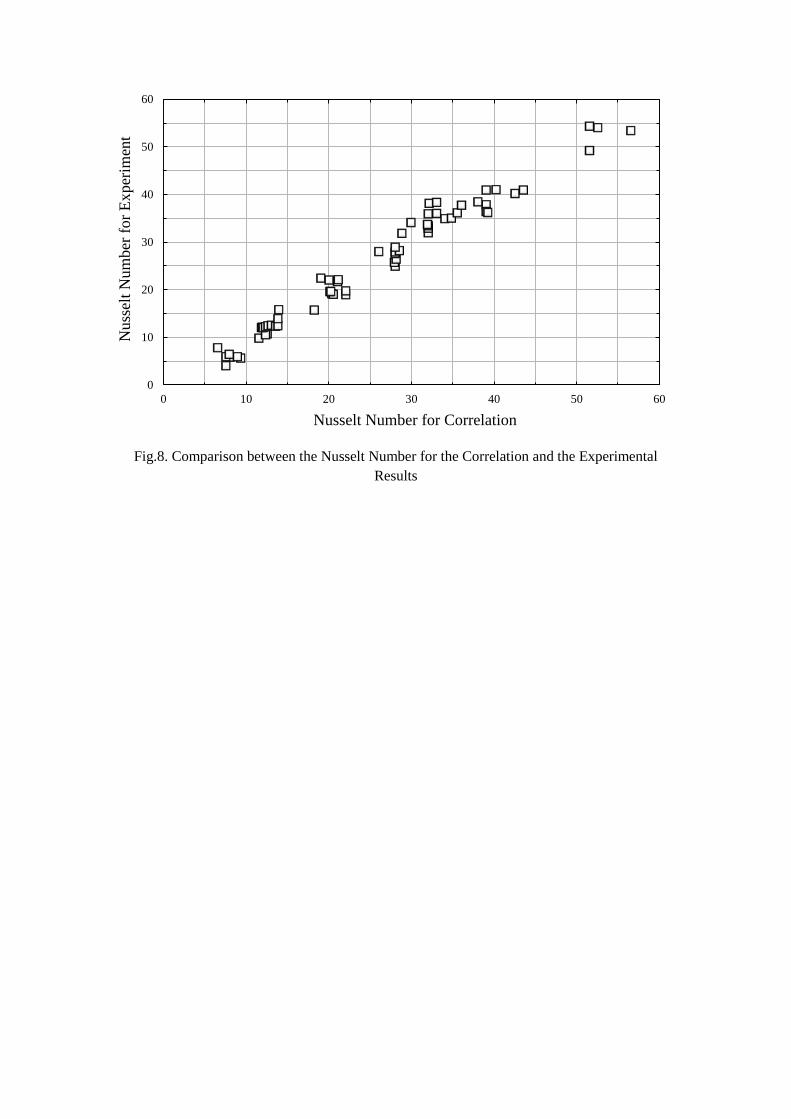
Fig.8. Comparison between the Nusselt Number for the Correlation and the Experimental Results
0
10
20
30
40
50
60
0 10 20 30 40 50 60
Nus
selt
Num
ber f
or E
xper
imen
t
Nusselt Number for Correlation