Embed Size (px)
Citation preview

Organized by Hosted by In collaboration with Supported by
Experiment of Experiment of Experiment of Experiment of Magnetic Resonant Coupling Magnetic Resonant Coupling Magnetic Resonant Coupling Magnetic Resonant Coupling
ThreeThreeThreeThree----phase Wireless Power Transferphase Wireless Power Transferphase Wireless Power Transferphase Wireless Power Transfer
Yusuke Tanikawa, Masaki Kato, Takehiro Imura,
Yoichi Hori
Organized by Hosted by In collaboration with Supported by
2/26
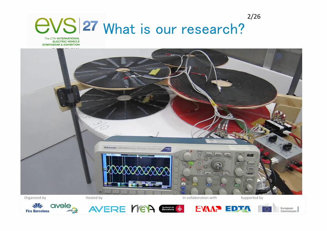
What is our research?

Organized by Hosted by In collaboration with Supported by
3/26
0. What is our study? : Movie
1. Background of Wireless Power Transfer
1.1. General information of WPT
1.2. Why three phase?
2. Approach of our study
2.1. General info. & parameters
2.2. Theoretical formula
2.3. Experiment and result
3. Conclusion and future works
Contents

Organized by Hosted by In collaboration with Supported by
4/26
0. What is our study? : Movie
1. Background of Wireless Power Transfer
1.1. General information of WPT
1.2. Why three phase?
2. Approach of our study
2.1. General info. & parameters
2.2. Theoretical formula
2.3. Experiment and result
3. Conclusion and future works
Contents

Organized by Hosted by In collaboration with Supported by
5/26
Wireless Power Transfer (WPT)
Applications: EV, mobile, and battery charger
Conventional WPT: Single phaseAC transfer
1.1. General info. for WPT 1/3

Organized by Hosted by In collaboration with Supported by
6/26
MethodsMagnetic
InductionMagnetic Resonant
CouplingMicrowave
Images
Transfer Gap Up to 0.2 m Up to 10 m A few hundred km
Efficiency Up to 95% Up to 97% Up to 60 %
Robustness for
Displacement Poor Great Good
6/26
Three methods of WPT technologies
1.1. General info. for WPT 2/3

Organized by Hosted by In collaboration with Supported by
7/26
• Transmitter and receiver: LC resonators
• High efficiency (around 90%) at 1 m gap
• Transfer frequency: 100 kHz to 20 MHz
– Power devices for kHz switching
• Relay resonators (single phase)
– Suitable for charging EVs while running
Magnetic Resonant Coupling
1.1. General info. for WPT 3/3

Organized by Hosted by In collaboration with Supported by
8/26
1. Advantage for high power transfer
2. Suitable characteristics for WPT
~~~~
~~~~~~~~Z
Z
Z
a a'
b'c c'
N N'
++
b
1.2. Why three phase? 1/3

Organized by Hosted by In collaboration with Supported by
9/26
Advantages for high power transfer
Single phase Three phase
Power limit ratio 1 3
Device quantity 2 (4 switches, 2 lines) 3 (6 switches, 3 lines)
Circuits
• Larger power capacity with same devices– Capacity limit: three times of single phase
(High frequency devices: Low power limit)
• Relatively simple system
1.2. Why three phase? 2/3

Organized by Hosted by In collaboration with Supported by
10/26
Photo :Wikipedia Photo:Toyonaka industry WEB
Suitable characteristics for WPT
Conventional method
単相交流の整流電圧
-1.5
-1
-0.5
0
0.5
1
1.5
2
0 60 120 180 240 300 360
位相角[°]
×Vo
整流前波形
整流波形
Single phase 図 三相交流の全波整流
-1.5
-1
-0.5
0
0.5
1
1.5
2
0 60 120 180 240 300 360
位相角[°]
×V
o
U相 V相W相 整流波形
Three phase
AC (U)
AC (W)
AC
DC
AC (V)
DC
• Smaller ripples of rectified DC
• Rotation symmetry: contact-less terminal
1.2. Why three phase? 3/3

Organized by Hosted by In collaboration with Supported by
11/26
0. What is our study? : Movie
1. Background of Wireless Power Transfer
1.1. General information of WPT
1.2. Why three phase?
2. Approach of our study
2.1. General information & parameters
2.2. Theoretical formula
2.3. Experiment and result
3. Conclusion and future works
Contents

Organized by Hosted by In collaboration with Supported by
12/26
1. Comparison of data and theoretical formula
2. Rotation experiment: collection of measured values• Each 15 degree from 0 to 360 degree
• Mutual inductance between resonators
• Ratio of voltage (V), current (I), and power (P)
Mutual inductance
(Measured value)
Ratio between transmitter and receiver
(Calculated value)Formula
Receiver V, I, and P
(Measured value)
Ratio between transmitter and receiver
(Measured value)
ComparisonTransmitterV, I, and P
(Measured value)
2.1. General info. & parameters 1/2
Experiment Experiment Experiment Experiment & & & & analysis of Threeanalysis of Threeanalysis of Threeanalysis of Three----phase WPTphase WPTphase WPTphase WPT

Organized by Hosted by In collaboration with Supported by
13/26
Coupling coefficient
(nondimensionalized mutual inductance)
Efficiency (Power ratio)
Power factor = 1.0 (resonant condition)
Current ratio
1
2
I
IAi =
iv
in
out AAIV
IV
P
P⋅=
⋅⋅
==11
22ηH
L
L
L
L
Lk mmm
µ88021
===
Voltage ratio
1
2
V
VAv =
~~~~
~~~~ ~~~~
2nd side
1st side
V2
I2
I1V1 ~~~~
~~~~ ~~~~
~~~~
~~~~ ~~~~
~~~~
~~~~ ~~~~
~~~~~~~~
~~~~~~~~ ~~~~~~~~
2nd side
1st side
V2
I2
I1V1
mL
Receiver side
Transmitter side
2.1. General info. & parameters 2/2

Organized by Hosted by In collaboration with Supported by
14/26
Resonance: simple formula of mutual inductance and load resistance
At experiment; RL=50 ohm
Base theoretical formula of single phasemL LR
22110 CLCL ==ω Voltage ratio
Current ratio
Efficiency (Power ratio)
),()( 2
0211
0
1
2Lmv
mL
Lmv RLA
LRRRR
RLj
V
VA =
++==
ωω
),()( 2
0
1
2Lmi
L
mi RLA
RR
Lj
I
IA =
+==
ω
)()(
)(2
02112
2
0
mLL
Lmiv
LRRRRRR
RLAA
ωω
η+++
=⋅=Masaki Kato, Takehiro Imura, Yoichi Hori, “The Characteristics when Changing Transmission Distance
and Load Value in Wireless Power Transfer via Magnetic Resonance Coupling”,
The 34th International Telecommunications Energy Conference (INTELEC 34th), 2012
2.2. Theoretical formula 1/3

Organized by Hosted by In collaboration with Supported by
15/26
• Three phase; a lot of mutual inductance values
To adapt the single phase formula;
how to combine the values into one value?
• Combination of trigonometric function
)sin()()(
)3
2sin()
3sin()sin(
~
133221
2
3
2
2
2
1
321
φω
πω
πωω
+++−++=
++++=
tLLLLLLLLL
tLtLtLL
mmmmmmmmm
mmmm
Combined Lm
Phase difference
++−++
−−=
++−++
−=
)()(
)2/()2/(cos
)()(
)2/3()2/3(sin
133221
2
3
2
2
2
1
321
133221
2
3
2
2
2
1
32
mmmmmmmmm
mmm
mmmmmmmmm
mm
LLLLLLLLL
LLL
LLLLLLLLL
LL
φ
φ
Modification of formula to three phase
~~~~
~~~~ ~~~~
2nd side
1st side
V2
I2
I1V1 ~~~~
~~~~ ~~~~
~~~~
~~~~ ~~~~
~~~~
~~~~ ~~~~
~~~~~~~~
~~~~~~~~ ~~~~~~~~
2nd side
1st side
V2
I2
I1V1
mL
Receiver side
Transmitter side~~~~
~~~~ ~~~~
2nd side
1st side
V2
I2
I1V1 ~~~~
~~~~ ~~~~
~~~~
~~~~ ~~~~
~~~~
~~~~ ~~~~
~~~~~~~~
~~~~~~~~ ~~~~~~~~
2nd side
1st side
V2
I2
I1V1
mL
Receiver side
Transmitter side
2.2. Theoretical formula 2/3

Organized by Hosted by In collaboration with Supported by
16/26
• Efficient formula: function of load resistance
• Optimal value of load resistance
2
0
1
22
2 )( mL LR
RRR ω+=
)()(
)(2
02112
2
0
mLL
Lmiv
LRRRRRR
RLAA
ωω
η+++
=⋅=
Optimal load for efficient maximization
2.2. Theoretical formula 3/3

Organized by Hosted by In collaboration with Supported by
17/26
• Resonant frequency: 120 kHz
• Cable: Y connection
– Rotation symmetry
– 50 ohm load resistance
• Resonators Phase a Phase b Phase c
Self inductance[μH] 8.73×10² 8.68×10² 8.69×10²
Internal resistance[Ω] 1.21 1.23 1.12
Resonant capacitance[pF ] 2.04×10³ 2.09×10³ 2.04×10³
Quality factor 5.46×10² 5.36×10² 5.89×10²
Resonant frequency[kHz] 1.19×10² 1.19×10² 1.20×10²
Self inductance[μH] 8.67×10² 8.69×10² 8.69×10²
Internal resistance[Ω] 1.17 1.23 1.20
Resonant capacitance[pF ] 2.07×10³ 2.03×10³ 2.04×10³
Quality factor 5.63×10² 5.36×10² 5.49×10²
Resonant frequency[kHz] 1.19×10² 1.20×10² 1.20×10²
Cable: 2 mm2
Diameter: 1.7 mm
Pitch of coil: 2.5 mm
Capacitor: 2000 pF
Receiver
Transm
itter
2.3. Experiment 1/7 (Setting)

Organized by Hosted by In collaboration with Supported by
18/26
A-A
B-A
C-A
0.10 0.200.000
240
120 60
180
300
0
240
120 60
180
300
[deg]
mLkH
L
L
L
L
Lk mmm
µ88021
===
Combined mutual inductance;
calculated from measured values
Mutual inductance (Coupling coefficient )
mLk
2.3. Experiment 2/7 (Result 1/6)
Close position: small rotation angle
Strong coupling

Organized by Hosted by In collaboration with Supported by
19/26
最適負荷
LR
0
240
120 60
180
300
[deg]
][Ω18060 120
最適負荷
LR
0
240
120 60
180
300
[deg]0
240
120 60
180
300
0
240
120 60
180
300
[deg]
][Ω18060 120
2
0
1
22
2 )( mL LR
RRR ω+=
Similar shape to mutual inductance
Optimal load resistance
Optimal value
LZ
2.3. Experiment 3/7 (Result 2/6)

Organized by Hosted by In collaboration with Supported by
20/26
A-A
B-A
C-A
A-A Cal
B-A Cal
C-A Cal
150 270300
240
120 60
180
300
[deg]
[deg]
A-A
B-A
C-A
A-A Cal
B-A Cal
C-A Cal
150 270300
240
120 60
180
300
[deg]0
240
120 60
180
300
0
240
120 60
180
300
[deg]
[deg]
0-45 degree; phase = -90 degree
60 degree; phase = 180 degree
75-120degree; phase = 150degree
=-120-90+360 degree
++−++
−−=
++−++
−=
)()(
)2/()2/(cos
)()(
)2/3()2/3(sin
133221
2
3
2
2
2
1
321
133221
2
3
2
2
2
1
32
LLLLLLLLL
LLL
LLLLLLLLL
LA
φ
φ
Precise shape
Between calculation and
measured value
Phase difference of voltageφ2.3. Experiment 4/7 (Result 3/6)

Organized by Hosted by In collaboration with Supported by
21/26
Calculated value < Measured value
At optimal load; circular shape
At 60 degree,
Voltage ratio is maximum.
2
0211
0
)( mL
Lmv
LRRRR
RLjA
ωω
++=
Voltage ratiovA
2.3. Experiment 5/7 (Result 4/6)
Organized by Hosted by In collaboration with Supported by
22/26
50[Ω]負荷 計算値50[Ω]負荷 実測値最適負荷 計算値
2.0 3.01.0
iA
)( 2
0
RR
LjA
L
mi +=
ω
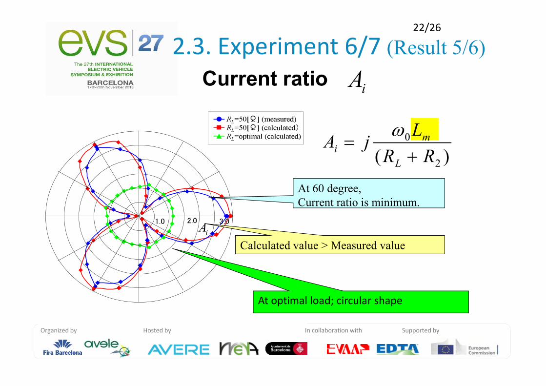
Calculated value > Measured value
At optimal load; circular shape
At 60 degree,
Current ratio is minimum.
Current ratioiA
2.3. Experiment 6/7 (Result 5/6)

Organized by Hosted by In collaboration with Supported by
23/26
50[Ω]負荷 計算値50[Ω]負荷 実測値最適負荷計算値
0.4 1.00 0.6 0.80.2η
0
240
120 60
180
300
[deg]
50[Ω]負荷 計算値50[Ω]負荷 実測値最適負荷計算値
0.4 1.00 0.6 0.80.2η
0
240
120 60
180
300
[deg]0
240
120 60
180
300
0
240
120 60
180
300
[deg] 0-45 degree: 80%
60 degree:35%75-120 degree:80%
Maximum deference of
calculated and measured value;
at 60 degree
Efficiency (Power ratio)
2.3. Experiment 7/7 (Result 6/6)

Organized by Hosted by In collaboration with Supported by
24/26
0. What is our study? : Movie
1. Background of Wireless Power Transfer
1.1. General information of WPT
1.2. Why three phase?
2. Approach of our study
2.1. General information & parameters
2.2. Theoretical formula
2.3. Experiment and result
3. Conclusion and future works
Contents

Organized by Hosted by In collaboration with Supported by
25/26
3. Conclusion & future works
• Experiment and analysis of Three-phase WPT
– 1. Comparison of data and theoretical formula
Each formula draws the similar calculated value as measured value
– 2. Rotation experiment
Rotation symmetry of transmitters are shown in experimental result
• Future works
– High power experiment and analysis
– Coupling analysis as cross coupling.
Organized by Hosted by In collaboration with Supported by
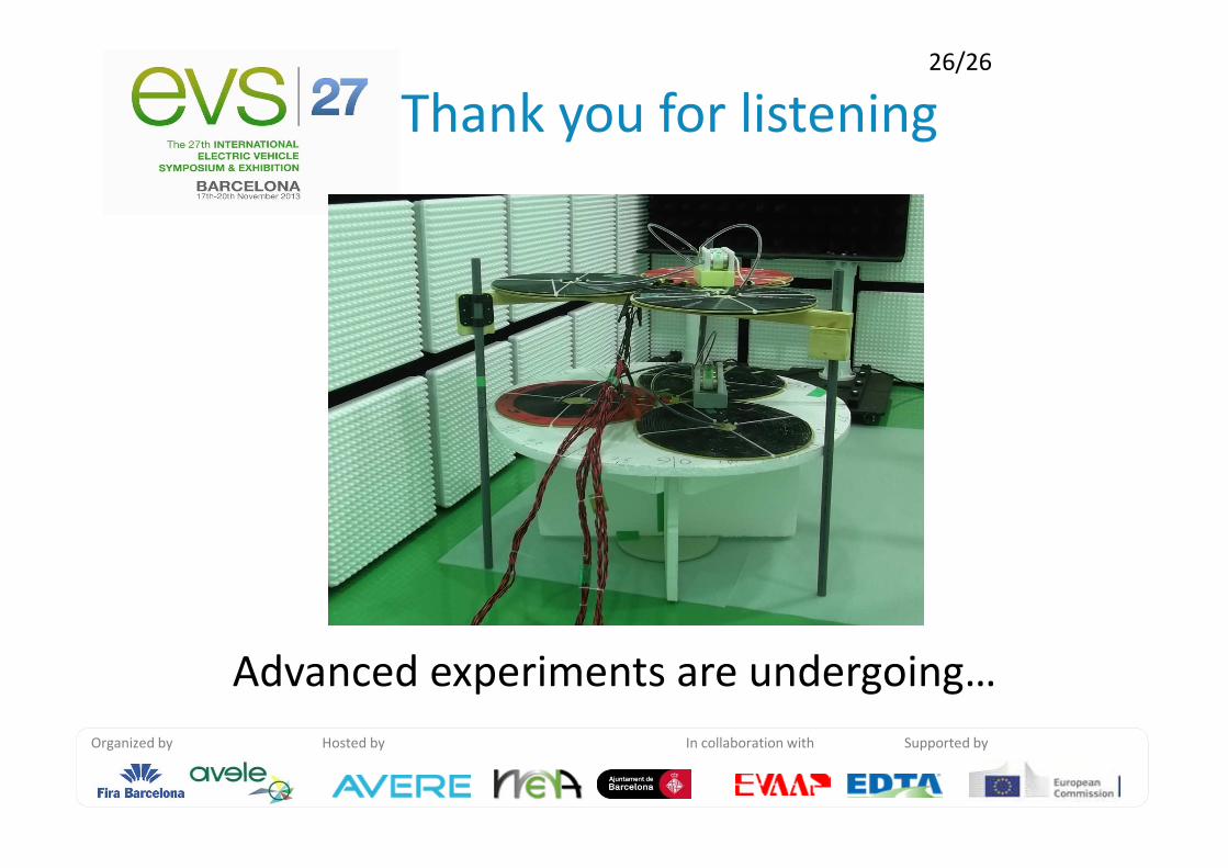
Thank you for listening26/26
Advanced experiments are undergoing…

Organized by Hosted by In collaboration with Supported by
Appendix

Organized by Hosted by In collaboration with Supported by
Current
Voltage
Power
DC-DC Efficiency
Device efficiency
%83830.0884.0
737.0===η
WPT efficiency
Receiver voltage
Transmitter voltage

Organized by Hosted by In collaboration with Supported by
回路構成
50Hz
Inv.v Load
(Leaf)
DC電源可変電圧
定電流モード有り
高周波インバータ 共振器 整流器負荷
50Hzインバータ+Leaf または20Ω琺瑯抵抗

Organized by Hosted by In collaboration with Supported by

Organized by Hosted by In collaboration with Supported by
)3
2sin()
3sin()sin(
)sin()2
3
2
3()
22(
)cos()2
3
2
3()sin()
22(
3
2sin)cos(
3
2cos)sin(
3
sin)cos(3
cos)sin(
)sin(
)3
2sin()
3sin()sin(
321
2
32
2321
3232
1
3
2
1
321
πω
πωω
φω
ωω
πω
πω
πω
πω
ω
πω
πωω
++++
+−+−−=
−+−−=
++
++
=
++++
tAtAtA
tAAAA
A
tAAtAA
A
ttA
ttA
tA
tAtAtA

Organized by Hosted by In collaboration with Supported by
線間電圧と相電圧
対称Y形起電力において
ea====Em1sin(ωωωω t−−−− 0°)++++Em3sin3ωωωωt++++Em5sin(5ωωωωt−−−− 0°)++++ •••
eb====Em1sin(ωωωω t−−−−120°)++++Em3sin3ωωωω t++++Em5sin(5ωωωω t−−−−240°)++++ •••
ec====Em1sin(ωωωω t−−−−240°)++++Em3sin3ωωωω t++++Em5sin(5ωωωω t−−−−120°)++++ •••
~~~~ ea
eb
ec~~~~~~~~
a
bc
N
+
++
eab
ebc
eca
各線間電圧は eab====ea−−−−eb====Em1sinωωωωt−−−−sin(ωωωω t−−−−120°)++++Em5sin5ωωωωt−−−−sin(5ωωωωt−−−−240°)++++ •••
線間電圧に三倍次高調波はあらわれない
Organized by Hosted by In collaboration with Supported by
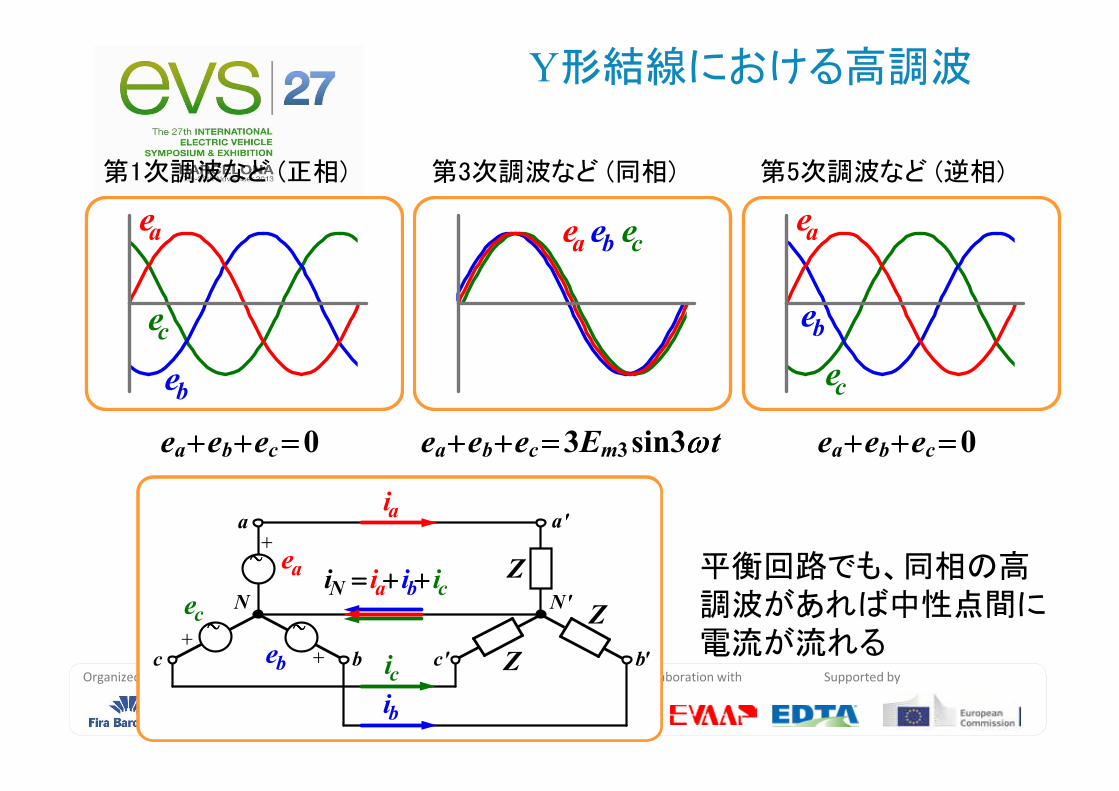
Y形結線における高調波
ea
eb
ec
ea eb ecea
eb
ec
第1次調波など (正相) 第3次調波など (同相) 第5次調波など (逆相)
ea++++eb++++ec====0 ea++++eb++++ec====3Em3sin3ωωωω t ea++++eb++++ec====0
~~~~ ea
eb
ec~~~~~~~~
Z
Z
Z
a a'
b b'c c'
N N'
+
++
~~~~ ea
eb
ec~~~~~~~~
Z
Z
Z
a a'
b b'c c'
N N'
+
++
ia
ib
ic
iN ==== ia++++ ib++++ ic平衡回路でも、同相の高調波があれば中性点間に電流が流れる

Organized by Hosted by In collaboration with Supported by
Delta connection with harmonic waves
第1次調波など (正相) 第3次調波など (同相) 第5次調波など (逆相)
ea++++eb++++ec====0 ea++++eb++++ec====3Em3sin3ωωωωt ea++++eb++++ec====0
平衡回路でも同相の高調波があれば起電力回路に循環電流が流れる
igigig
ig====ea++++eb++++ecZag++++Zbg++++Zcg
ig====ea++++eb++++ecZag++++Zbg++++Zcg~~~~~~~~
eab
ebc
eca~~~~~~~~
~~~~~~~~Zbc
Zca Zab
a a'
b b'c c'
+
+
+
Zal
Zbl
Zcl
Zbg
Zag
Zcg

Organized by Hosted by In collaboration with Supported by
0 phase current
ea====e(t)====Em1sinωωωω t++++Em3sin3ωωωω t ++++Em5sin5ωωωω t++++ •••
eb====e(t−−−−T/3)====Em1sinωωωω(t−−−−T/3)++++Em3sin3ωωωω(t−−−−T/3)++++Em5sin5ωωωω(t−−−−T/3)++++ •••
====Em1sin(ωωωω t−−−−120°)++++Em3sin(3ωωωω t )++++Em5sin(5ωωωω t−−−−240°)++++ •••
ec====e(t−−−−2T/3)====Em1sin(ωωωω t−−−−240°)++++Em3sin(3ωωωω t )++++Em5sin(5ωωωω t−−−−120°)++++ •••

Organized by Hosted by In collaboration with Supported by
Previous research
• induction

Organized by Hosted by In collaboration with Supported by
Analysis for previous research
• Induction without magnetic resonant coupling
Ladder coil transmitter for rail transport
– Small air gap
– Three phase receivers are original of us
–