Embed Size (px)
Citation preview
Lehrerheft zur ExperimentierboxExperiment Description/Manual for the Science Kit
Electric Circuits
Electric Circuits
22
© 2009 Cornelsen Experimenta, Berlin
All rights reserved.
The work and parts of it are protected by copyright. Every use for other than the legal cases requires the previous written agreement by Cornelsen Experimenta.Hint to §§ 46, 52a UrhG: Neither the work or parts of it are allowed to be scanned, put into a network or other-wise to be made publicly available without such an agreement. This includes intranets of schools or other educational institutions.
Cornelsen Experimenta products are designed for educational use only and are not intended for use in industrial, medical or commercial applications.
We assume no liability for damages which are caused by inappropriate usage of the equipment.
Electric Circuits
3
Science Kit
Electric CircuitsOrder no. 31772This Science Kit is recommended for students at the age of 8–9.
Contents
List of Components ..............................................................................................4
Storing diagram ...................................................................................................5
1 Special learning aims ........................................................................................6
2. Experiments ..........................................................................................7
2.1 Electric current flows .............................................................................7
2.1.1 Batteries and bulbs ..................................................................................7
2.1.2 The glass of the bulb ...............................................................................7
2.1.3 Battery test .............................................................................................7
2.2 Electric circuits .......................................................................................8
2.2.1 Simple circuit ..........................................................................................8
2.2.2 Series circuit ............................................................................................8
2.2.3 Parallel circuit ..........................................................................................8
2.2.4 The switch in the circuit ..........................................................................9
2.2.5 Building our own switch ..........................................................................9
2.2.6 Assembling a vehicle with two headlights ..............................................10
2.2.7 The headlight-test .................................................................................11
2.2.8 Trembling through a rollercoaster .........................................................12
2.3 Conductivity of materials ....................................................................12
2.3.1 Which materials conduct the electrical current? .....................................12
2.4 Danger through electric current .........................................................13
2.4.1 Electric current from the socket .............................................................13
2.4.2 Caution! High voltage! ..........................................................................13
2.5 Electric current generates heat ...........................................................13
2.5.1 Electric current generates heat ..............................................................13
2.6 Electric current sets in motion ............................................................14
2.6.1 The electromagnet ................................................................................14
3. Underlying principles ..........................................................................14
4. Important information ........................................................................15
Electric Circuits
44
List of components
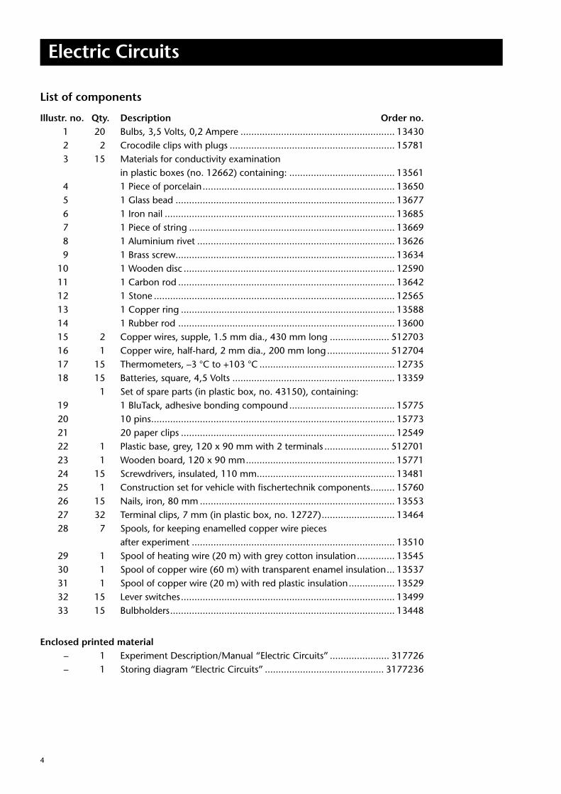
Illustr. no. Qty. Description Order no. 1 20 Bulbs, 3,5 Volts, 0,2 Ampere ......................................................... 13430 2 2 Crocodile clips with plugs ............................................................. 15781 3 15 Materials for conductivity examination in plastic boxes (no. 12662) containing: ....................................... 13561 4 1 Piece of porcelain ....................................................................... 13650 5 1 Glass bead ................................................................................. 13677 6 1 Iron nail ..................................................................................... 13685 7 1 Piece of string ............................................................................ 13669 8 1 Aluminium rivet ......................................................................... 13626 9 1 Brass screw................................................................................. 13634 10 1 Wooden disc .............................................................................. 12590 11 1 Carbon rod ................................................................................ 13642 12 1 Stone ......................................................................................... 12565 13 1 Copper ring ............................................................................... 13588 14 1 Rubber rod ................................................................................ 13600 15 2 Copper wires, supple, 1.5 mm dia., 430 mm long ...................... 512703 16 1 Copper wire, half-hard, 2 mm dia., 200 mm long ....................... 512704 17 15 Thermometers, –3 °C to +103 °C .................................................. 12735 18 15 Batteries, square, 4,5 Volts ............................................................ 13359 1 Set of spare parts (in plastic box, no. 43150), containing: 19 1 BluTack, adhesive bonding compound ....................................... 15775 20 10 pins .......................................................................................... 15773 21 20 paper clips ............................................................................... 12549 22 1 Plastic base, grey, 120 x 90 mm with 2 terminals ........................ 512701 23 1 Wooden board, 120 x 90 mm ....................................................... 15771 24 15 Screwdrivers, insulated, 110 mm................................................... 13481 25 1 Construction set for vehicle with fischertechnik components ......... 15760 26 15 Nails, iron, 80 mm ........................................................................ 13553 27 32 Terminal clips, 7 mm (in plastic box, no. 12727) ........................... 13464 28 7 Spools, for keeping enamelled copper wire pieces after experiment ........................................................................... 13510 29 1 Spool of heating wire (20 m) with grey cotton insulation .............. 13545 30 1 Spool of copper wire (60 m) with transparent enamel insulation ... 13537 31 1 Spool of copper wire (20 m) with red plastic insulation ................. 13529 32 15 Lever switches ............................................................................... 13499 33 15 Bulbholders ................................................................................... 13448
Enclosed printed material – 1 Experiment Description/Manual “Electric Circuits” ...................... 317726 – 1 Storing diagram “Electric Circuits” ............................................ 3177236
Electric Circuits
5
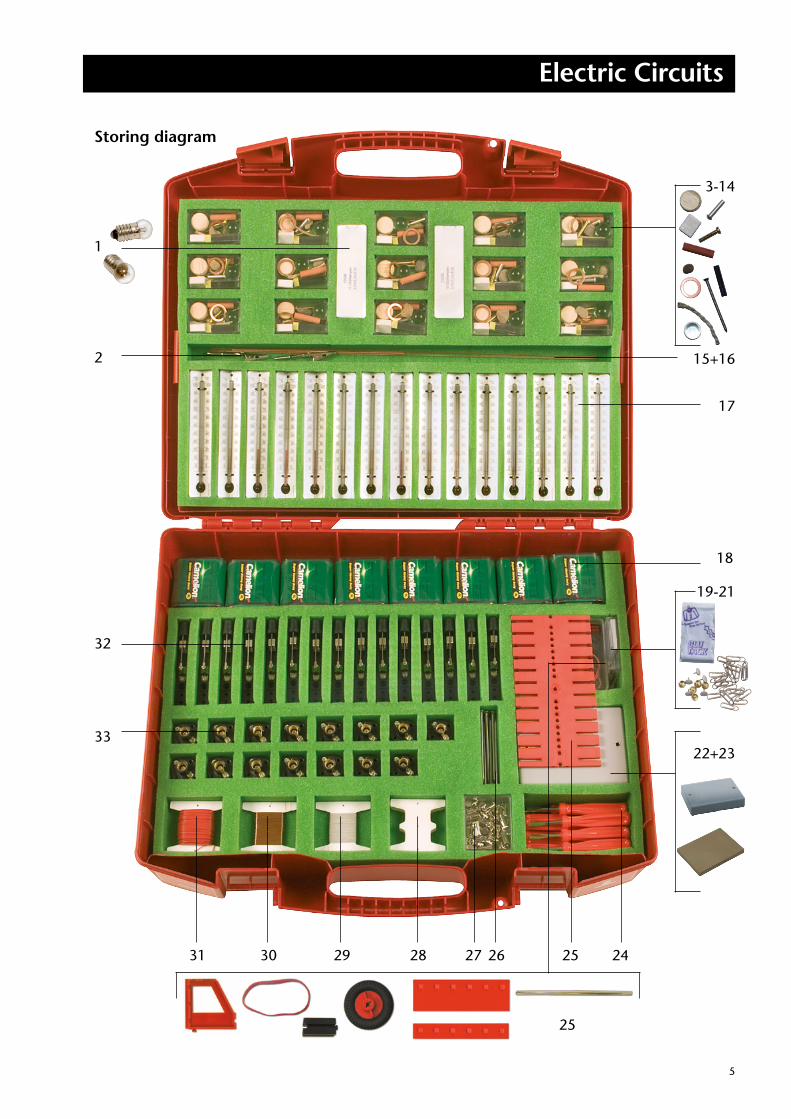
Storing diagram
3-14
15+16
17
18
19-21
22+23
25
2425262728293031
1
2
33
32
Electric Circuits
66
1. Special learning aims
1.1 Electric current flows
1.2 Electric circuits
1.3 Conductivity of materials
1.4 Danger through electric current
1.5 Electric current generates heat
1.6 Electric current sets in motion
Please note:
Check the copper wires before con necting them. The insula-tion at the wire ends must be stripped off !
Electric Circuits
7
2. Experiments
2.1 Electric current flows
2.1.1 Batteries and bulbs
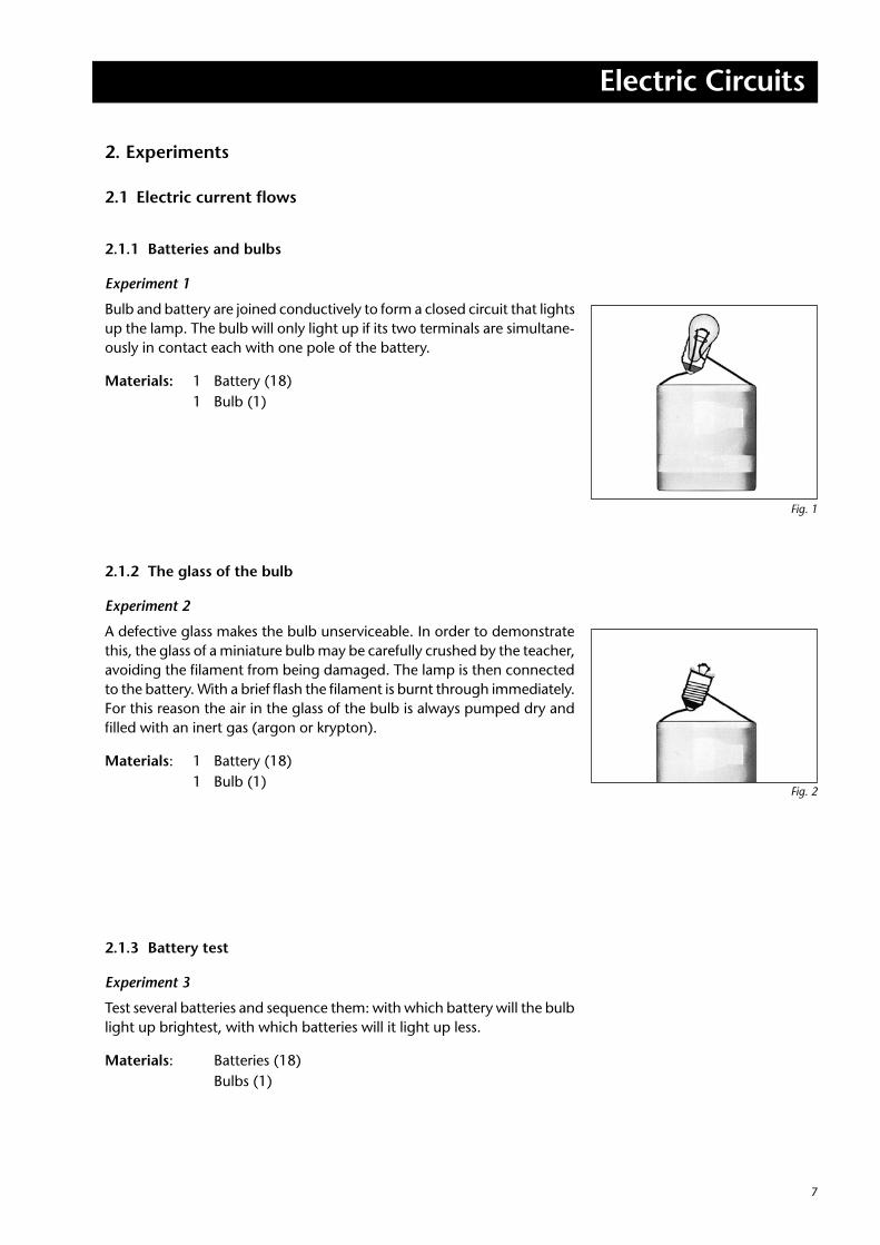
Experiment 1
Bulb and battery are joined conductively to form a closed circuit that lights up the lamp. The bulb will only light up if its two terminals are simultane-ously in contact each with one pole of the battery.
Materials: 1 Battery (18) 1 Bulb (1)
2.1.2 The glass of the bulb
Experiment 2
A defective glass makes the bulb unserviceable. In order to demonstrate this, the glass of a miniature bulb may be carefully crushed by the teacher, avoiding the filament from being damaged. The lamp is then connected to the battery. With a brief flash the filament is burnt through immediately. For this reason the air in the glass of the bulb is always pumped dry and filled with an inert gas (argon or krypton).
Materials: 1 Battery (18) 1 Bulb (1)
2.1.3 Battery test
Experiment 3
Test several batteries and sequence them: with which battery will the bulb light up brightest, with which batteries will it light up less.
Materials: Batteries (18) Bulbs (1)
Fig. 1
Fig. 2
Electric Circuits
88
2.2 Electric curcuits
2.2.1 Simple circuit
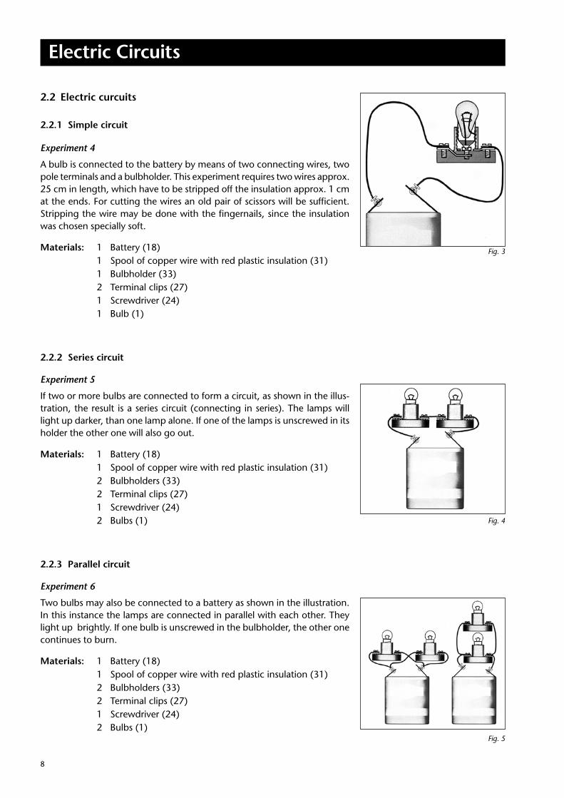
Experiment 4
A bulb is connected to the battery by means of two connecting wires, two pole terminals and a bulbholder. This experiment requires two wires approx. 25 cm in length, which have to be stripped off the insulation approx. 1 cm at the ends. For cutting the wires an old pair of scissors will be sufficient. Stripping the wire may be done with the fingernails, since the insulation was chosen specially soft.
Materials: 1 Battery (18) 1 Spool of copper wire with red plastic insulation (31) 1 Bulbholder (33) 2 Terminal clips (27) 1 Screwdriver (24) 1 Bulb (1)
2.2.2 Series circuit
Experiment 5
If two or more bulbs are connected to form a circuit, as shown in the illus-tration, the result is a series circuit (connecting in series). The lamps will light up darker, than one lamp alone. If one of the lamps is unscrewed in its holder the other one will also go out.
Materials: 1 Battery (18) 1 Spool of copper wire with red plastic insulation (31) 2 Bulbholders (33) 2 Terminal clips (27) 1 Screwdriver (24) 2 Bulbs (1)
2.2.3 Parallel circuit
Experiment 6
Two bulbs may also be connected to a battery as shown in the illustration. In this instance the lamps are connected in parallel with each other. They light up brightly. If one bulb is unscrewed in the bulbholder, the other one continues to burn.
Materials: 1 Battery (18) 1 Spool of copper wire with red plastic insulation (31) 2 Bulbholders (33) 2 Terminal clips (27) 1 Screwdriver (24) 2 Bulbs (1)
Fig. 3
Fig. 4
Fig. 5
Electric Circuits
9
2.2.4 The switch in the circuit
Experiment 7
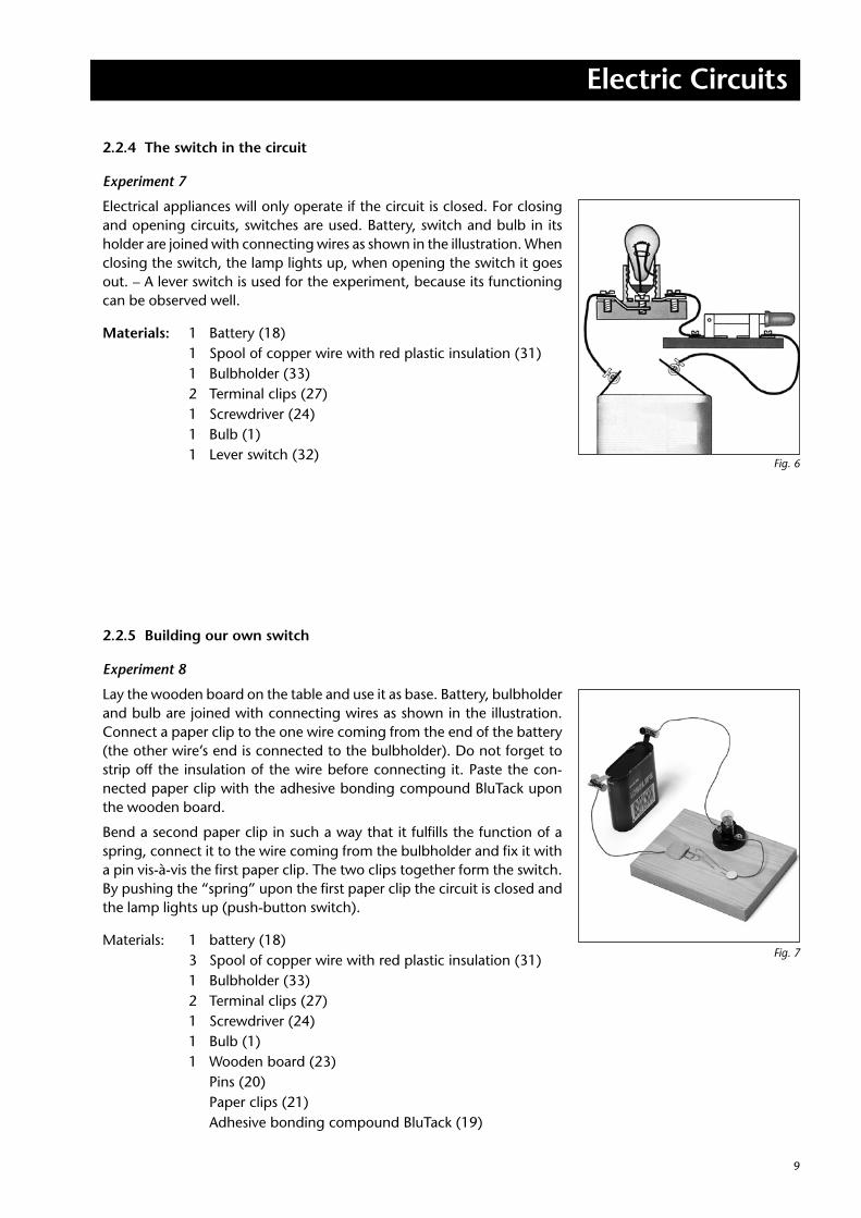
Electrical appliances will only operate if the circuit is closed. For closing and opening circuits, switches are used. Battery, switch and bulb in its holder are joined with connecting wires as shown in the illustration. When closing the switch, the lamp lights up, when opening the switch it goes out. – A lever switch is used for the experiment, because its functioning can be observed well.
Materials: 1 Battery (18) 1 Spool of copper wire with red plastic insulation (31) 1 Bulbholder (33) 2 Terminal clips (27) 1 Screwdriver (24) 1 Bulb (1) 1 Lever switch (32)
2.2.5 Building our own switch
Experiment 8
Lay the wooden board on the table and use it as base. Battery, bulbholder and bulb are joined with connecting wires as shown in the illustration. Connect a paper clip to the one wire coming from the end of the battery (the other wire’s end is connected to the bulbholder). Do not forget to strip off the insulation of the wire before connecting it. Paste the con-nected paper clip with the adhesive bonding compound BluTack upon the wooden board.
Bend a second paper clip in such a way that it fulfills the function of a spring, connect it to the wire coming from the bulbholder and fix it with a pin vis-à-vis the first paper clip. The two clips together form the switch. By pushing the “spring” upon the first paper clip the circuit is closed and the lamp lights up (push-button switch).
Materials: 1 battery (18) 3 Spool of copper wire with red plastic insulation (31) 1 Bulbholder (33) 2 Terminal clips (27) 1 Screwdriver (24) 1 Bulb (1) 1 Wooden board (23) Pins (20) Paper clips (21) Adhesive bonding compound BluTack (19)
Fig. 6
Fig. 7
Electric Circuits
1010
2.2.6 Assembling a vehicle with two headlights
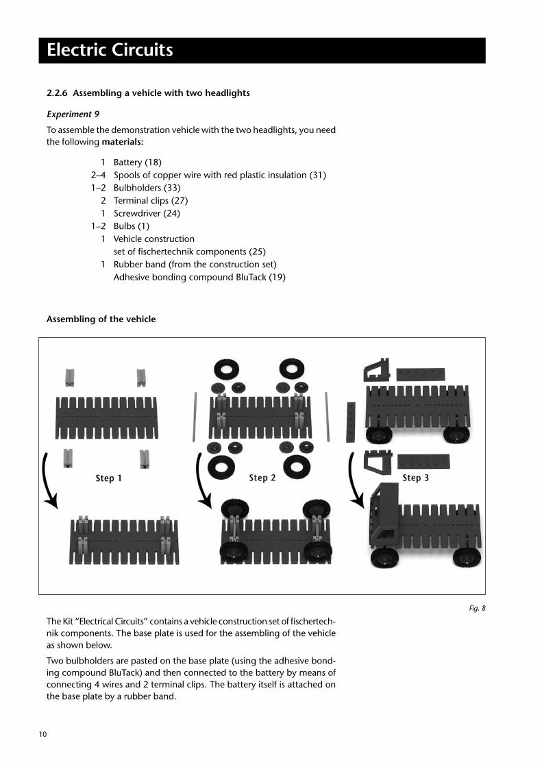
Experiment 9
To assemble the demonstration vehicle with the two headlights, you need the following materials:
1 Battery (18) 2–4 Spools of copper wire with red plastic insulation (31) 1–2 Bulbholders (33) 2 Terminal clips (27) 1 Screwdriver (24) 1–2 Bulbs (1) 1 Vehicle construction set of fischertechnik components (25) 1 Rubber band (from the construction set) Adhesive bonding compound BluTack (19)
Assembling of the vehicle
The Kit “Electrical Circuits” contains a vehicle construction set of fischertech-nik components. The base plate is used for the assembling of the vehicle as shown below.
Two bulbholders are pasted on the base plate (using the adhesive bond-ing compound BluTack) and then connected to the battery by means of connecting 4 wires and 2 terminal clips. The battery itself is attached on the base plate by a rubber band.
Fig. 8
Electric Circuits
11
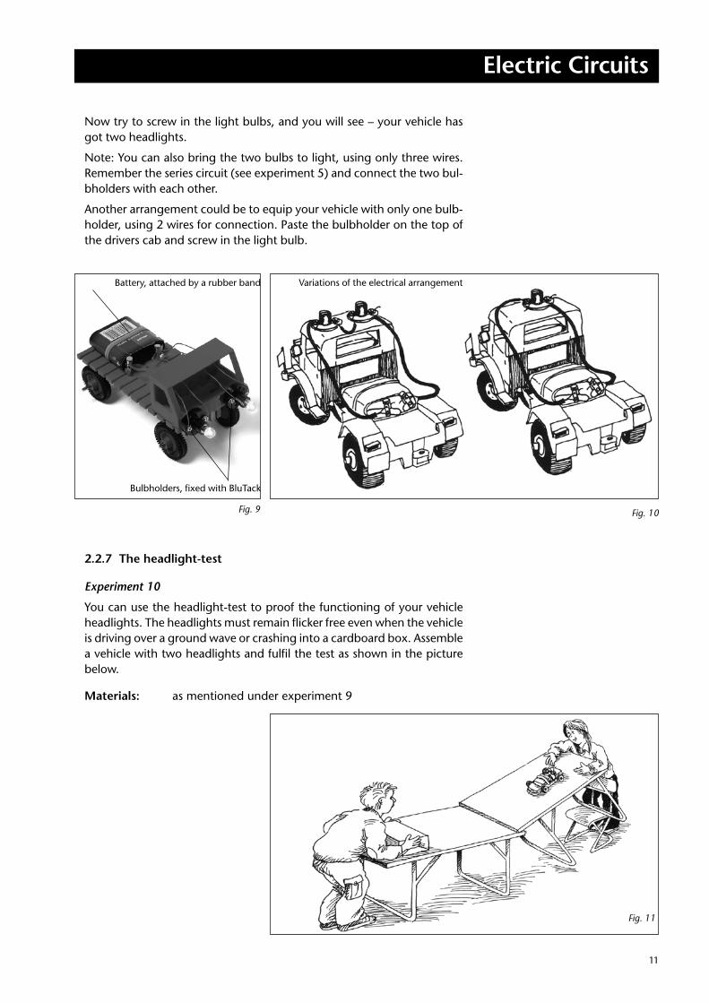
Now try to screw in the light bulbs, and you will see – your vehicle has got two headlights.
Note: You can also bring the two bulbs to light, using only three wires. Remember the series circuit (see experiment 5) and connect the two bul-bholders with each other.
Another arrangement could be to equip your vehicle with only one bulb-holder, using 2 wires for connection. Paste the bulbholder on the top of the drivers cab and screw in the light bulb.
2.2.7 The headlight-test
Experiment 10
You can use the headlight-test to proof the functioning of your vehicle headlights. The headlights must remain flicker free even when the vehicle is driving over a ground wave or crashing into a cardboard box. Assemble a vehicle with two headlights and fulfil the test as shown in the picture below.
Materials: as mentioned under experiment 9
Bulbholders, fixed with BluTack
Battery, attached by a rubber band Variations of the electrical arrangement
Fig. 9 Fig. 10
Fig. 11
Electric Circuits
1212
2.2.8 Trembling through a rollercoaster
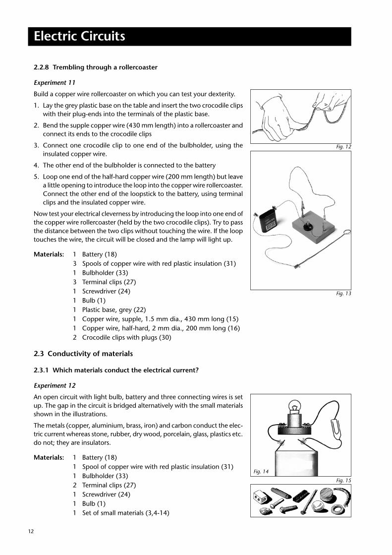
Experiment 11
Build a copper wire rollercoaster on which you can test your dexterity.
1. Lay the grey plastic base on the table and insert the two crocodile clips with their plug-ends into the terminals of the plastic base.
2. Bend the supple copper wire (430 mm length) into a rollercoaster and connect its ends to the crocodile clips
3. Connect one crocodile clip to one end of the bulbholder, using the insulated copper wire.
4. The other end of the bulbholder is connected to the battery
5. Loop one end of the half-hard copper wire (200 mm length) but leave a little opening to introduce the loop into the copper wire rollercoaster. Connect the other end of the loopstick to the battery, using terminal clips and the insulated copper wire.
Now test your electrical cleverness by introducing the loop into one end of the copper wire rollercoaster (held by the two crocodile clips). Try to pass the distance between the two clips without touching the wire. If the loop touches the wire, the circuit will be closed and the lamp will light up.
Materials: 1 Battery (18) 3 Spools of copper wire with red plastic insulation (31) 1 Bulbholder (33) 3 Terminal clips (27) 1 Screwdriver (24) 1 Bulb (1) 1 Plastic base, grey (22) 1 Copper wire, supple, 1.5 mm dia., 430 mm long (15) 1 Copper wire, half-hard, 2 mm dia., 200 mm long (16) 2 Crocodile clips with plugs (30)
2.3 Conductivity of materials
2.3.1 Which materials conduct the electrical current?
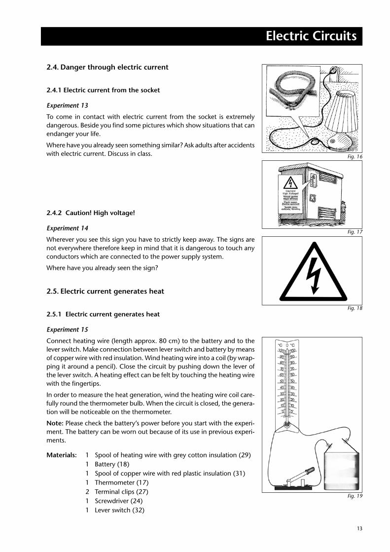
Experiment 12
An open circuit with light bulb, battery and three connecting wires is set up. The gap in the circuit is bridged alternatively with the small materials shown in the illustrations.
The metals (copper, aluminium, brass, iron) and carbon conduct the elec-tric current whereas stone, rubber, dry wood, porcelain, glass, plastics etc. do not; they are insulators.
Materials: 1 Battery (18) 1 Spool of copper wire with red plastic insulation (31) 1 Bulbholder (33) 2 Terminal clips (27) 1 Screwdriver (24) 1 Bulb (1) 1 Set of small materials (3,4-14)
Fig. 12
Fig. 13
Fig. 15
Fig. 14
Electric Circuits
13
2.4. Danger through electric current
2.4.1 Electric current from the socket
Experiment 13
To come in contact with electric current from the socket is extremely dangerous. Beside you find some pictures which show situations that can endanger your life.
Where have you already seen something similar? Ask adults after accidents with electric current. Discuss in class.
2.4.2 Caution! High voltage!
Experiment 14
Wherever you see this sign you have to strictly keep away. The signs are not everywhere therefore keep in mind that it is dangerous to touch any conductors which are connected to the power supply system.
Where have you already seen the sign?
2.5. Electric current generates heat
2.5.1 Electric current generates heat
Experiment 15
Connect heating wire (length approx. 80 cm) to the battery and to the lever switch. Make connection between lever switch and battery by means of copper wire with red insulation. Wind heating wire into a coil (by wrap-ping it around a pencil). Close the circuit by pushing down the lever of the lever switch. A heating effect can be felt by touching the heating wire with the fingertips.
In order to measure the heat generation, wind the heating wire coil care-fully round the thermometer bulb. When the circuit is closed, the genera-tion will be noticeable on the thermometer.
Note: Please check the battery’s power before you start with the experi-ment. The battery can be worn out because of its use in previous experi-ments.
Materials: 1 Spool of heating wire with grey cotton insulation (29) 1 Battery (18) 1 Spool of copper wire with red plastic insulation (31) 1 Thermometer (17) 2 Terminal clips (27) 1 Screwdriver (24) 1 Lever switch (32)
Fig. 16
Fig. 17
Fig. 18
Fig. 19
Electric Circuits
1414
2.6 Electric current sets in motion
2.6.1 The electromagnet
Experiment 16
An iron coil which is wrapped around by a wire is an electro-magnet. The large nail is wound with enamelled wire (length approx. 1 m) after transparent enamel has been scraped off the ends. A connection to the battery and the lever switch is made. The connection between lever switch and battery is made by means of connecting wire (red insulation). Close the circuit with the lever switch and the large nail will get magnetized. Then position the small nail as shown. It is attracted by the large nail which functions as an electromagnet when the current passes through.
Materials: 1 Spool of copper wire with transparent enamel insulation (30) 1 Battery (18) 1 Spool of copper wire with red plastic insulation (31) 2 Terminal clips (27) 1 Screwdriver (24) 1 Lever switch (32) 1 Large nail (26) 1 Small nail (6)
Galvanic elementSquare battery
3 Underlying principles
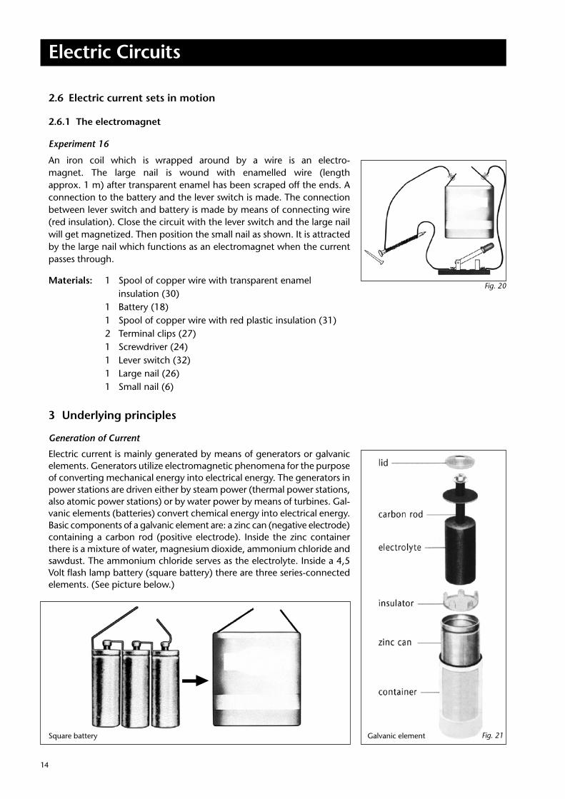
Generation of Current
Electric current is mainly generated by means of generators or galvanic elements. Generators utilize electromagnetic phenomena for the purpose of converting mechanical energy into electrical energy. The generators in power stations are driven either by steam power (thermal power stations, also atomic power stations) or by water power by means of turbines. Gal-vanic elements (batteries) convert chemical energy into electrical energy. Basic components of a galvanic element are: a zinc can (negative electrode) containing a carbon rod (positive electrode). Inside the zinc container there is a mixture of water, magnesium dioxide, ammonium chloride and sawdust. The ammonium chloride serves as the electrolyte. Inside a 4,5 Volt flash lamp battery (square battery) there are three series-connected elements. (See picture below.)
Fig. 20
Fig. 21
Electric Circuits
15
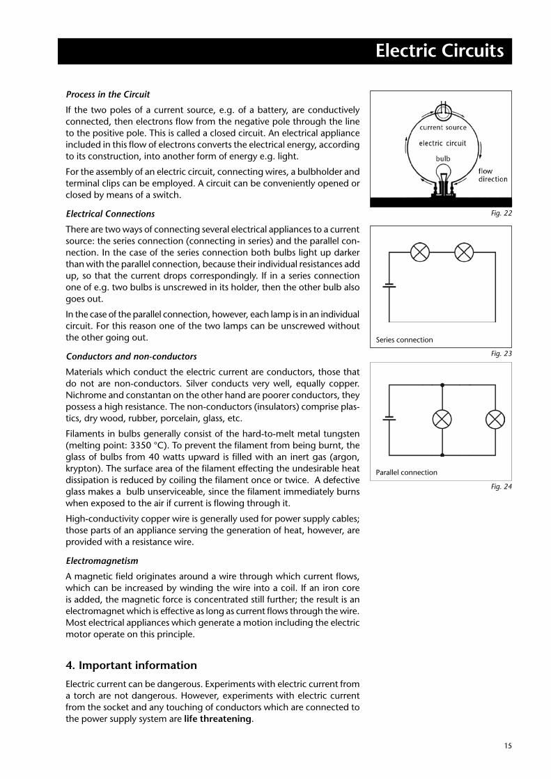
Process in the Circuit
If the two poles of a current source, e.g. of a battery, are conductively connected, then electrons flow from the negative pole through the line to the positive pole. This is called a closed circuit. An electrical appliance included in this flow of electrons converts the electrical energy, according to its construction, into another form of energy e.g. light.
For the assembly of an electric circuit, connecting wires, a bulbholder and terminal clips can be employed. A circuit can be conveniently opened or closed by means of a switch.
Electrical Connections
There are two ways of connecting several electrical appliances to a current source: the series connection (connecting in series) and the parallel con-nection. In the case of the series connection both bulbs light up darker than with the parallel connection, because their individual resistances add up, so that the current drops correspondingly. If in a series connection one of e.g. two bulbs is unscrewed in its holder, then the other bulb also goes out.
In the case of the parallel connection, however, each lamp is in an individual circuit. For this reason one of the two lamps can be unscrewed without the other going out.
Conductors and non-conductors
Materials which conduct the electric current are conductors, those that do not are non-conductors. Silver conducts very well, equally copper. Nichrome and constantan on the other hand are poorer conductors, they possess a high resistance. The non-conductors (insulators) comprise plas-tics, dry wood, rubber, porcelain, glass, etc.
Filaments in bulbs generally consist of the hard-to-melt metal tungsten (melting point: 3350 °C). To prevent the filament from being burnt, the glass of bulbs from 40 watts upward is filled with an inert gas (argon, krypton). The surface area of the filament effecting the undesirable heat dissipation is reduced by coiling the filament once or twice. A defective glass makes a bulb unserviceable, since the filament immediately burns when exposed to the air if current is flowing through it.
High-conductivity copper wire is generally used for power supply cables; those parts of an appliance serving the generation of heat, however, are provided with a resistance wire.
Electromagnetism
A magnetic field originates around a wire through which current flows, which can be increased by winding the wire into a coil. If an iron core is added, the magnetic force is concentrated still further; the result is an electromagnet which is effective as long as current flows through the wire. Most electrical appliances which generate a motion including the electric motor operate on this principle.
4. Important information
Electric current can be dangerous. Experiments with electric current from a torch are not dangerous. However, experiments with electric current from the socket and any touching of conductors which are connected to the power supply system are life threatening.
Parallel connection
Series connection
Fig. 22
Fig. 23
Fig. 24
© 2009 Cornelsen Experimenta, Berlin 08.00
Holzhauser Straße 76 Tel.: +49 30 435 902-0 eMail: [email protected] Berlin/Germany Fax: +49 30 435 902-22 Internet: www.corex.de
Experiment Description/Manual Science Kit “Electric Circuits”
Order no. 31772 6