Embed Size (px)
Citation preview
1
EXPERIMENT 3 - Part I:
DSB-SC Amplitude Modulation
OBJECTIVE
To generate DSB-SC amplitude modulated signal.
PRELIMINARY DISCUSSION
In the modulation process, the message signal (the baseband voice, video, etc.) modifies a higher-frequency
signal called the carrier, which is usually a sinusoidal wave. As the name suggests, in amplitude
modulation, the information signal varies the amplitude of the carrier.
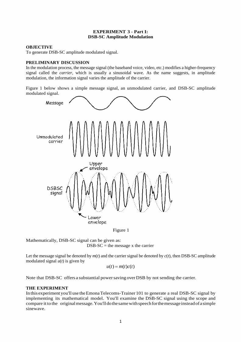
Figure 1 below shows a simple message signal, an unmodulated carrier, and DSB-SC amplitude
modulated signal.
Figure 1
Mathematically, DSB-SC signal can be given as:
DSB-SC = the message x the carrier
Let the message signal be denoted by m(t) and the carrier signal be denoted by c(t), then DSB-SC amplitude
modulated signal u(t) is given by
( ) ( ) ( )u t m t c t
Note that DSB-SC offers a substantial power saving over DSB by not sending the carrier.
THE EXPERIMENT
In this experiment you'll use the Emona Telecoms-Trainer 101 to generate a real DSB-SC signal by
implementing its mathematical model. You'll examine the DSB-SC signal using the scope and
compare it to the original message. You'll do the same with speech for the message instead of a simple
sinewave.
2
Equipment
• Emona Telecoms-Trainer 101 (plus power-pack)
• Dual channel 20MHz oscilloscope
• two Emona Telecoms-Trainer 101 oscilloscope leads
• assorted Emona Telecoms-Trainer 101 patch leads
Procedure
Part A - Generating a DSB-SC signal using a simple message
1. Gather a set of the equipment listed above.
2. Set up the scope. Ensure that:
• the Trigger Source control is set to the CH1 (or INT) position.
• the Mode control is set to the CH1 position.
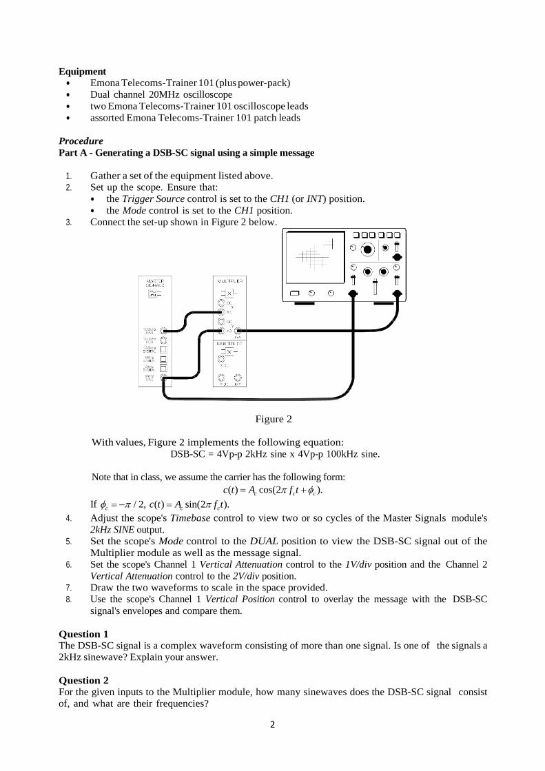
3. Connect the set-up shown in Figure 2 below.
Figure 2
With values, Figure 2 implements the following equation:
DSB-SC = 4Vp-p 2kHz sine x 4Vp-p 100kHz sine.
Note that in class, we assume the carrier has the following form:
( ) cos(2 ).c c cc t A f t
If / 2,c ( ) sin(2 ).c cc t A f t
4. Adjust the scope's Timebase control to view two or so cycles of the Master Signals module's
2kHz SINE output.
5. Set the scope's Mode control to the DUAL position to view the DSB-SC signal out of the
Multiplier module as well as the message signal.
6. Set the scope's Channel 1 Vertical Attenuation control to the 1V/div position and the Channel 2
Vertical Attenuation control to the 2V/div position.
7. Draw the two waveforms to scale in the space provided.
8. Use the scope's Channel 1 Vertical Position control to overlay the message with the DSB-SC
signal's envelopes and compare them.
Question 1
The DSB-SC signal is a complex waveform consisting of more than one signal. Is one of the signals a
2kHz sinewave? Explain your answer.
Question 2
For the given inputs to the Multiplier module, how many sinewaves does the DSB-SC signal consist
of, and what are their frequencies?
3
Question 3
State advantage(s) of DSB-SC signals over DSB signals?
Part B - Generating a DSB-SC signal using speech
This part of the experiment lets you see what a DSB-SC signal looks like when modulated by speech.
9. Disconnect the plugs to the Master Signals module's 2kHz SINE output.
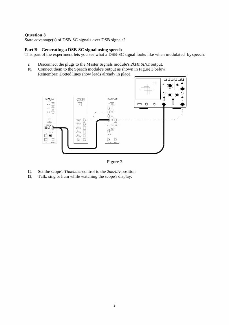
10. Connect them to the Speech module's output as shown in Figure 3 below.
Remember: Dotted lines show leads already in place.
Figure 3
11. Set the scope's Timebase control to the 2ms/div position.
12. Talk, sing or hum while watching the scope's display.
4
EXPERIMENT 3 - Part II:
DSB-SC Demodulation
OBJECTIVE
To demodulate DSB-SC amplitude modulated signal via product detector and to investigate effects of
the carrier synchronization on the product detector’s performance.
PRELIMINARY DISCUSSION
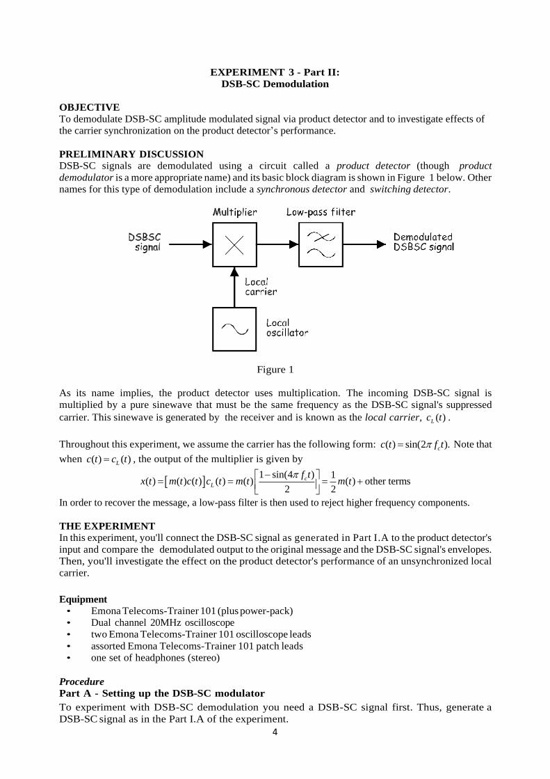
DSB-SC signals are demodulated using a circuit called a product detector (though product
demodulator is a more appropriate name) and its basic block diagram is shown in Figure 1 below. Other
names for this type of demodulation include a synchronous detector and switching detector.
Figure 1
As its name implies, the product detector uses multiplication. The incoming DSB-SC signal is
multiplied by a pure sinewave that must be the same frequency as the DSB-SC signal's suppressed
carrier. This sinewave is generated by the receiver and is known as the local carrier, ( )Lc t .
Throughout this experiment, we assume the carrier has the following form: ( ) sin(2 ).cc t f t Note that
when ( ) ( )Lc t c t , the output of the multiplier is given by
1 sin(4 ) 1
( ) ( ) ( ) ( ) ( ) ( ) other terms2 2
cL
f tx t m t c t c t m t m t
In order to recover the message, a low-pass filter is then used to reject higher frequency components.
THE EXPERIMENT
In this experiment, you'll connect the DSB-SC signal as generated in Part I.A to the product detector's
input and compare the demodulated output to the original message and the DSB-SC signal's envelopes.
Then, you'll investigate the effect on the product detector's performance of an unsynchronized local
carrier.
Equipment
• Emona Telecoms-Trainer 101 (plus power-pack)
• Dual channel 20MHz oscilloscope
• two Emona Telecoms-Trainer 101 oscilloscope leads
• assorted Emona Telecoms-Trainer 101 patch leads
• one set of headphones (stereo)
Procedure
Part A - Setting up the DSB-SC modulator
To experiment with DSB-SC demodulation you need a DSB-SC signal first. Thus, generate a
DSB-SC signal as in the Part I.A of the experiment.
5
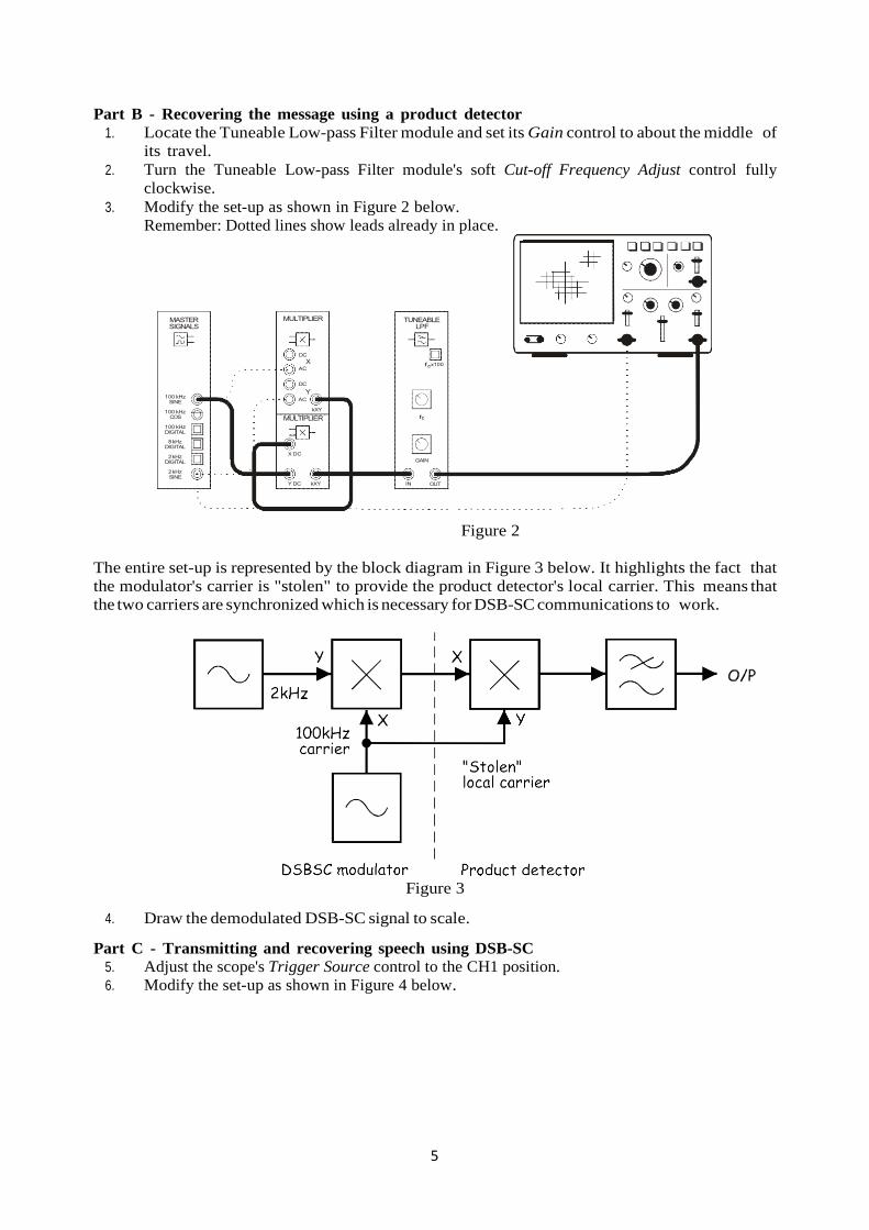
Part B - Recovering the message using a product detector
1. Locate the Tuneable Low-pass Filter module and set its Gain control to about the middle of
its travel.
2. Turn the Tuneable Low-pass Filter module's soft Cut-off Frequency Adjust control fully
clockwise.
3. Modify the set-up as shown in Figure 2 below.
Remember: Dotted lines show leads already in place.
Figure 2
The entire set-up is represented by the block diagram in Figure 3 below. It highlights the fact that
the modulator's carrier is "stolen" to provide the product detector's local carrier. This means that
the two carriers are synchronized which is necessary for DSB-SC communications to work.
Figure 3
4. Draw the demodulated DSB-SC signal to scale.
Part C - Transmitting and recovering speech using DSB-SC
5. Adjust the scope's Trigger Source control to the CH1 position.
6. Modify the set-up as shown in Figure 4 below.
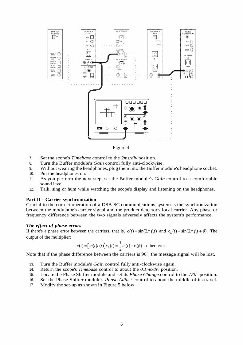
6
Figure 4
7. Set the scope's Timebase control to the 2ms/div position.
8. Turn the Buffer module's Gain control fully anti-clockwise.
9. Without wearing the headphones, plug them into the Buffer module's headphone socket.
10. Put the headphones on.
11. As you perform the next step, set the Buffer module's Gain control to a comfortable
sound level.
12. Talk, sing or hum while watching the scope's display and listening on the headphones.
Part D - Carrier synchronization
Crucial to the correct operation of a DSB-SC communications system is the synchronization
between the modulator's carrier signal and the product detector's local carrier. Any phase or
frequency difference between the two signals adversely affects the system's performance.
The effect of phase errors
If there's a phase error between the carriers, that is, ( ) sin(2 )cc t f t and ( ) sin(2 )L cc t f t . The
output of the multiplier:
1
( ) ( ) ( ) ( ) ( )cos( ) other terms2
Lx t m t c t c t m t
Note that if the phase difference between the carriers is 900, the message signal will be lost.
13. Turn the Buffer module's Gain control fully anti-clockwise again.
14. Return the scope's Timebase control to about the 0.1ms/div position.
15. Locate the Phase Shifter module and set its Phase Change control to the 180° position.
16. Set the Phase Shifter module's Phase Adjust control to about the middle of its travel.
17. Modify the set-up as shown in Figure 5 below.
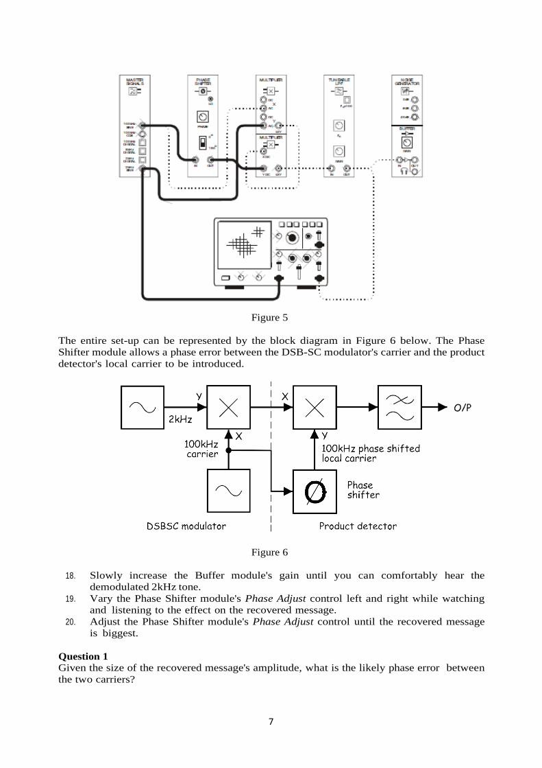
7
Figure 5
The entire set-up can be represented by the block diagram in Figure 6 below. The Phase
Shifter module allows a phase error between the DSB-SC modulator's carrier and the product
detector's local carrier to be introduced.
Figure 6
18. Slowly increase the Buffer module's gain until you can comfortably hear the
demodulated 2kHz tone.
19. Vary the Phase Shifter module's Phase Adjust control left and right while watching
and listening to the effect on the recovered message.
20. Adjust the Phase Shifter module's Phase Adjust control until the recovered message
is biggest.
Question 1
Given the size of the recovered message's amplitude, what is the likely phase error between
the two carriers?
8
21. Adjust the Phase Shifter module's Phase Adjust control until the recovered message
is smallest.
Question 2
Given the size of the recovered message's new amplitude, what is the likely phase error
between the two carriers?
The effect of frequency errors
There may be a frequency error between the DSB-SC signal's carrier and the product
detector's local carrier. If the error is small (say 0.1Hz) the two signals will alternately
reinforce and cancel each other which can render the message periodically inaudible but
otherwise intelligible. If the frequency error is larger (say 5Hz) the message is reasonably
intelligible but fidelity is poor. When frequency errors are large, intelligibility is seriously
affected.
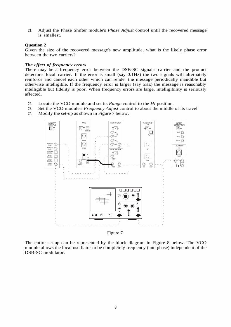
22. Locate the VCO module and set its Range control to the HI position.
23. Set the VCO module's Frequency Adjust control to about the middle of its travel.
24. Modify the set-up as shown in Figure 7 below.
Figure 7
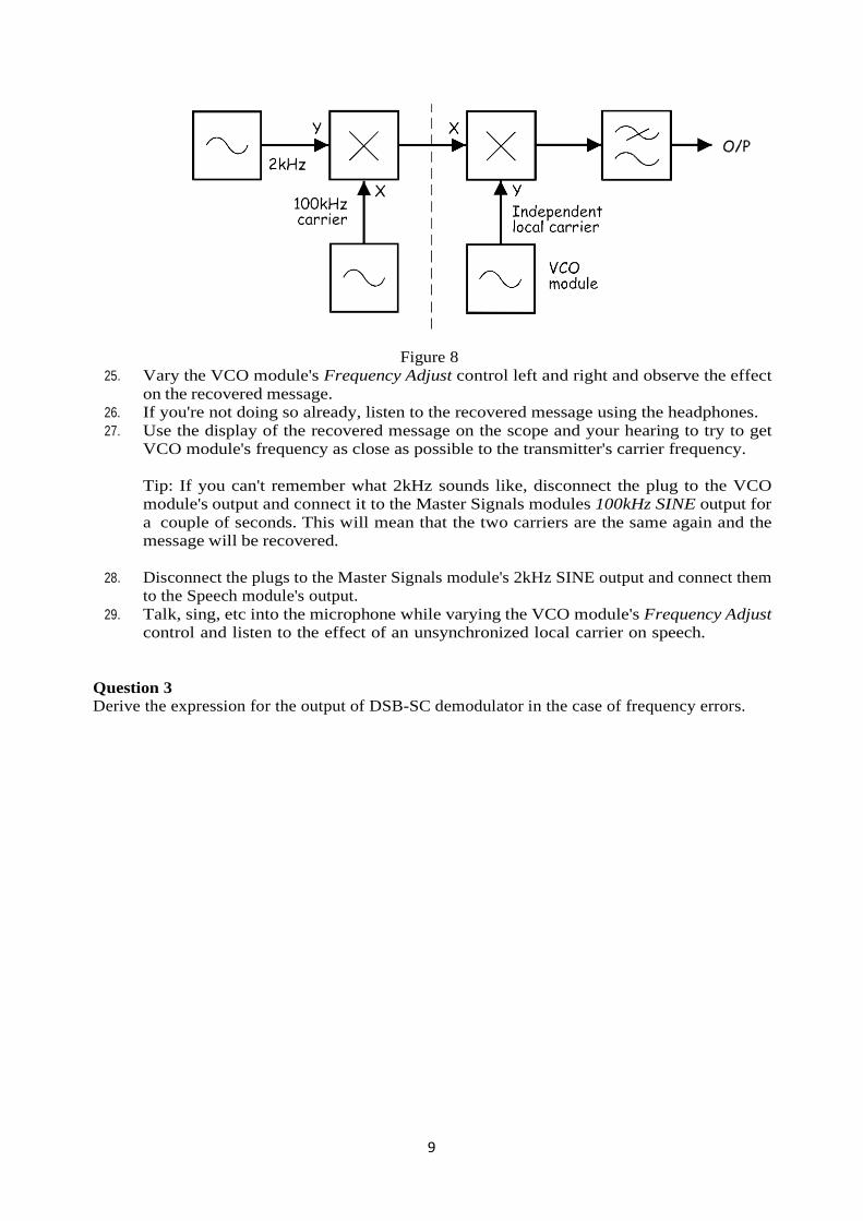
The entire set-up can be represented by the block diagram in Figure 8 below. The VCO
module allows the local oscillator to be completely frequency (and phase) independent of the
DSB-SC modulator.
9
Figure 8
25. Vary the VCO module's Frequency Adjust control left and right and observe the effect
on the recovered message.
26. If you're not doing so already, listen to the recovered message using the headphones.
27. Use the display of the recovered message on the scope and your hearing to try to get
VCO module's frequency as close as possible to the transmitter's carrier frequency.
Tip: If you can't remember what 2kHz sounds like, disconnect the plug to the VCO
module's output and connect it to the Master Signals modules 100kHz SINE output for
a couple of seconds. This will mean that the two carriers are the same again and the
message will be recovered.
28. Disconnect the plugs to the Master Signals module's 2kHz SINE output and connect them
to the Speech module's output.
29. Talk, sing, etc into the microphone while varying the VCO module's Frequency Adjust
control and listen to the effect of an unsynchronized local carrier on speech.
Question 3
Derive the expression for the output of DSB-SC demodulator in the case of frequency errors.