Embed Size (px)
Citation preview
7/27/2019 ExperiencesInsulators of HVDC Lines in Itaipu-TL
http://slidepdf.com/reader/full/experiencesinsulators-of-hvdc-lines-in-itaipu-tl 1/15
1
CIGRE HVDC Meeting
Buenos Aires
June 4th to 7th 2008-05-21
HVDC TOUGHENED GLASS INSULATORS
25 YEARS OF EXPERIENCE IN ITAIPU AND MORE
Luis Fernando FERREIRA Jean-Marie GEORGE
ELECTROVIDRO SEVES SEDIVER
Brazil France
The largest HVDC system in Latin America has now been operating for more than 25 years
from the Itaipu dam at the border between Brazil, Paraguay and Argentina. The overhead
lines of Itaipu I and II have successfully been using toughened glass insulators. The following
paper will present results obtained from insulators removed from these lines for evaluation,
adding more valuable information to global field experience of toughened glass insulators
used on HVDC systems. A review of current technology requirements for such applications is
also detailed in this paper.
1. ITAIPU HVDC overhead lines
Itaipu overhead line system is fit with toughened glass insulators on both AC and DC
lines.
For the DC system, it is important to understand that both lines are not equipped with
the same toughened glass technology. The first bipole is using standard glass while the
second bipole was equipped with HRTG special glass, designed from the experience
gained from the first bipole. The main difference resides in the resistivity of the glass
material and chemistry itself, as well as specific purity criteria in the making of glass.
The main observation from the field between the two bipoles is the difference in so
called “self shattering”. While the first line had relatively higher shattering, the second
bipole had a much better performance. Despite these shattering, both bipoles had
excellent operating records. In fact, even when shattered, the remaining stub remainssafe for the operation of the string.

7/27/2019 ExperiencesInsulators of HVDC Lines in Itaipu-TL
http://slidepdf.com/reader/full/experiencesinsulators-of-hvdc-lines-in-itaipu-tl 2/15
2
Electrical and mechanical tests performed on units removed from Itaipu and tested in
SEDIVER laboratories. The tests performed were:
¾ Mechanical strength test
¾ Mechanical residual strength test
¾ Thermo mechanical load test¾ Ionic migration test
2. The specific stress conditions of HVDC on insulators
HVDC by nature is creating a set of conditions quite remarkable and different from traditional
AC lines (5). The unidirectional E field is a main source of ionic effects on dielectric
materials. While IEC (1) is describing in detail the testing parameters and performanceexpectations of ceramic DC insulators (either glass or porcelain) it is not so the case for
composite DC application which is not covered by any standard. The question needs to be
asked, however, if highly strategic lines such as DC can afford to take the risk of unknown
performance, with organic inherently ageing materials, compared to the safety net provided
by stable and inert products, such as toughened glass, largely supported by decades of service.
Over the years, manufacturers’ have set up special materials and designs for HVDC, from the
dielectric itself to the end fittings. For toughened glass, the current design has largely
integrated the evolutions of the last 50 years field experience as can be seen in figure 1 and 2.
Figure 1 : Typical toughened glass insulator for HVDC application
7/27/2019 ExperiencesInsulators of HVDC Lines in Itaipu-TL
http://slidepdf.com/reader/full/experiencesinsulators-of-hvdc-lines-in-itaipu-tl 3/15
3
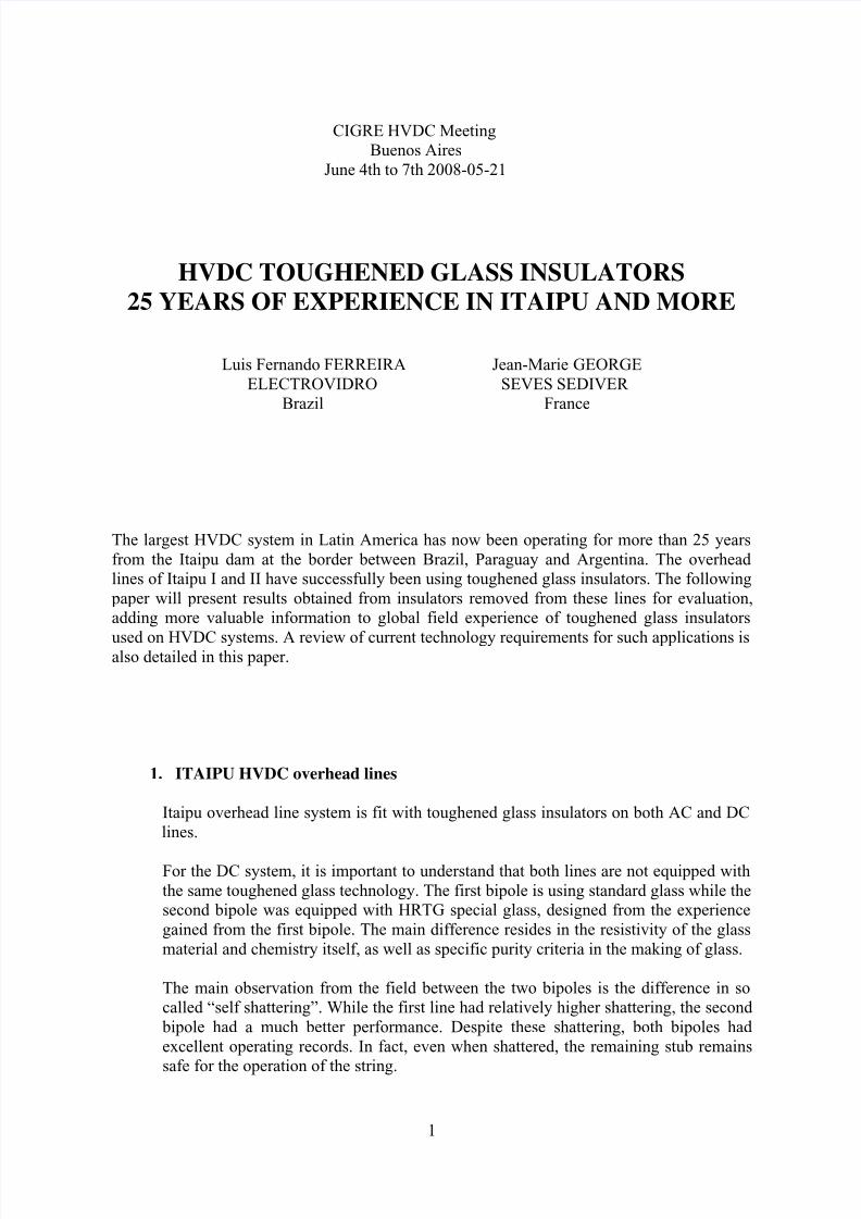
Figure 2 : Current DC toughened glass insulator with corrosion protection features on cap
and pin end fittings
Originally, standard glass or porcelain was used for HVDC. As a result of ionic
migration and the associated specific stress effect, several problems occurred leadingto punctures and outages on lines with standard porcelain (like for example in (2)), or
shattering of glass shells at levels higher than expected during the first years (3), (4).
Toughened glass, however, never led to the magnitude of problems encountered with
porcelain since a shattered unit does not generate any operational interruption or
disturbance.
The specific action of ionic migration corresponds to the migration of ions in the
glassy phase of the dielectric material under the unidirectional DC voltage. This glassy
phase exist in both glass and porcelain. Under the ionic effect of DC voltage, there is a
formation of a depletion layer where Na+ alkali cations have moved. This migration
through the silica network which forms the frame of glassy materials depends on theresistivity of the material itself. Ionic conductivity depends mainly on temperature, but
is also a function of the amount and type of alkali present in the dielectric (5).
A second effect of this migration, is a possible ionic accumulation in areas of
structural heterogeneity.
The second generation of DC glass, HRTG special glass composition has been
designed (6) around a better protection against corrosion (figure 2) and above all, a
much higher resistivity as shown in figure 3. This special chemistry of glass is locking
the ions through a much lower ionic conductivity in order to stop the migration under
DC voltage. Given this “immunity” against ionic stress, the adverse effects described
above and seen in the earlier applications have been eliminated. Additionally, special
process treatments in the glass moulding have led to a much higher purity of glass, and
therefore a lower impact to DC ionic accumulation.

7/27/2019 ExperiencesInsulators of HVDC Lines in Itaipu-TL
http://slidepdf.com/reader/full/experiencesinsulators-of-hvdc-lines-in-itaipu-tl 4/15

7/27/2019 ExperiencesInsulators of HVDC Lines in Itaipu-TL
http://slidepdf.com/reader/full/experiencesinsulators-of-hvdc-lines-in-itaipu-tl 5/15
5
Country Utility Project Year Voltage (kV)
BrazilFurnas Centrais
Foz Do Iguaçu-Sao Roque IHVDC Itaipu Transmission System
1984 600
Furnas Centrais Itaipu II 1987 600
Canada
BC Hydro Vancouver Saltspring-Stratford / Vancouver Island 1968 260
Atomic Energy of Canada Kettle-Winnipeg / Nelson River 1973 450Hydro Québec 6
THJames Bay 1988 450
China
Shanghai Super High Voltage Gezhouba Shanghai 1999 500
Southern Power Grids Co. Tianshengqiao-Guangdong 2001 500
Anhui Wuhu 2001 500
State Power Grids Co. 3 Gorges-Longta-Qinghai 2002 500
Southern Power Grid Guizhou-Guangdong 2003 500
Anhui Transmission Power Co. 2003 500
Denmark Elsam Skagerrak / Bulbjerg-Tjele 1987 250
Sweden+
Denmark
SSPB+
Elsam
Billdal-Kungsbacka-GothenburgAalborg-LaesoIsland
Konti Skan Project
1965 250
Denmark + Norway
Elsam+ NSPB
Bulbjerg-TjeleStoelen-Kristiansand Skagerrak Project
1976 250
Finland IVO International Ltd. Fenno Skan / Rihtniemi-Rauma 1988 400
IndiaPower Grid Corp. Rihand Dadri 1987 500
M.S.E.B. Chandrapur-Padghe 1997 500
Italy ENEL Corsican section – Italian section / Carbo Sarda 1968 200
MozambiqueHidroelectrica de Cahora Bassa Songo-Apollo / Cahora Bassa 1977 533
Hidroelectrica de Cahora Bassa Cahora Bassa 1995 533
New Zealand Transpower North South Island 1990 350
Norway
Statnett Skagerrak 1993 350
Statnett Skagerrak 1993 350
Statnett Skagerrak 1993 350
USA
BPA – PDWP - City of Los AngelesCelilo-Oregon Border Oregon Border-Sylmar / Pacific Intertie
1970 500
United Power Association Elk River Dickinson-Coal Creek / CU Project 1979 400
Vermont Electric Norton-Comerford Quebec-New England Intertie
1987 450
Table 1: Toughened glass HVDC applications
3. Performance evaluation of old insulators returned from BPA, USA
Out of many lines built over the last decades with toughened glass, some interesting feedback
was provided through utilities interested in testing old insulators removed from DC lines. As
an example, after more than 35 years in service, (insulators made in 1967) insulators from
BPA (Bonneville Power Administration, USA) have been removed from a 500kV DC line to
be tested. The goal of these tests was to make an assessment of their condition and evaluate
the possible modifications of their performance after more than 35 years on a DC line.
Several tests were performed:

7/27/2019 ExperiencesInsulators of HVDC Lines in Itaipu-TL
http://slidepdf.com/reader/full/experiencesinsulators-of-hvdc-lines-in-itaipu-tl 6/15
6
a) Dielectric test on the material
¾ ionic migration
b) Insulator testing
¾ mechanical strength test
¾ residual strength test
¾ thermo mechanical test
These tests were performed in CEB Laboratory, France and Saint Yorre laboratory France.
The overall condition of these insulators, as can be seen in figure 4 is excellent. There was a
zinc sleeve on the pin, and the fittings do not show any significant damage.
Figure 4: BPA 500kV DC insulators after more than 35 years in service.
Mechanical rating is 180kN
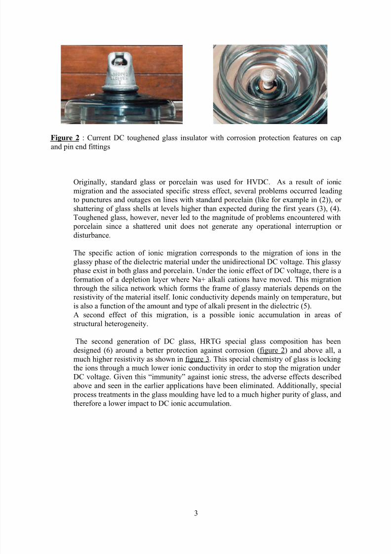
Ionic migration test
To verify the integrity of the dielectric under ionic migration conditions, 50 insulators were
tested as per IEC 61325 section 18. The Q50 conditions were evaluated as per this method,
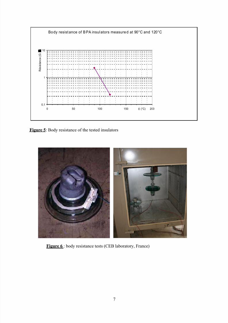
after determination of the body resistance (figure 5 and 6). The test was performed as shown
in figure 7.
7/27/2019 ExperiencesInsulators of HVDC Lines in Itaipu-TL
http://slidepdf.com/reader/full/experiencesinsulators-of-hvdc-lines-in-itaipu-tl 7/15
7
Figure 5: Body resistance of the tested insulators
Figure 6 : body resistance tests (CEB laboratory, France)
Bo dy resistance of B PA insulators measure d at 90°C and 120°C
0,1
1
10
0 50 100 150 200θ (°C)
R é s i s t a n c e ( G
)

7/27/2019 ExperiencesInsulators of HVDC Lines in Itaipu-TL
http://slidepdf.com/reader/full/experiencesinsulators-of-hvdc-lines-in-itaipu-tl 8/15
8
Test conditions were 70kV, and 90° C. The charge quantity calculated for the test to achieve
under these conditions the Q50 was 153C. A shattering occurred after 258C, equivalent to a
service time of 86 years. The test was stopped after 525C with no further evolution, which is
above 100 years of equivalent service time.
At this stage, we can conclude that the dielectric material itself is not modified, with a result
pointing out very clearly that the glass shell has not aged and kept its structure intact.
Mechanical strength
Ten insulators taken after they passed the ionic migration test were tested. The test was
performed as per IEC 60383 in Saint Yorre laboratory, France. The rating of the insulators is
180kN. The set up is shown in figure 8.
Figure 7: Ionic migration test. (CEB
laboratory, France)
7/27/2019 ExperiencesInsulators of HVDC Lines in Itaipu-TL
http://slidepdf.com/reader/full/experiencesinsulators-of-hvdc-lines-in-itaipu-tl 9/15

7/27/2019 ExperiencesInsulators of HVDC Lines in Itaipu-TL
http://slidepdf.com/reader/full/experiencesinsulators-of-hvdc-lines-in-itaipu-tl 10/15
10
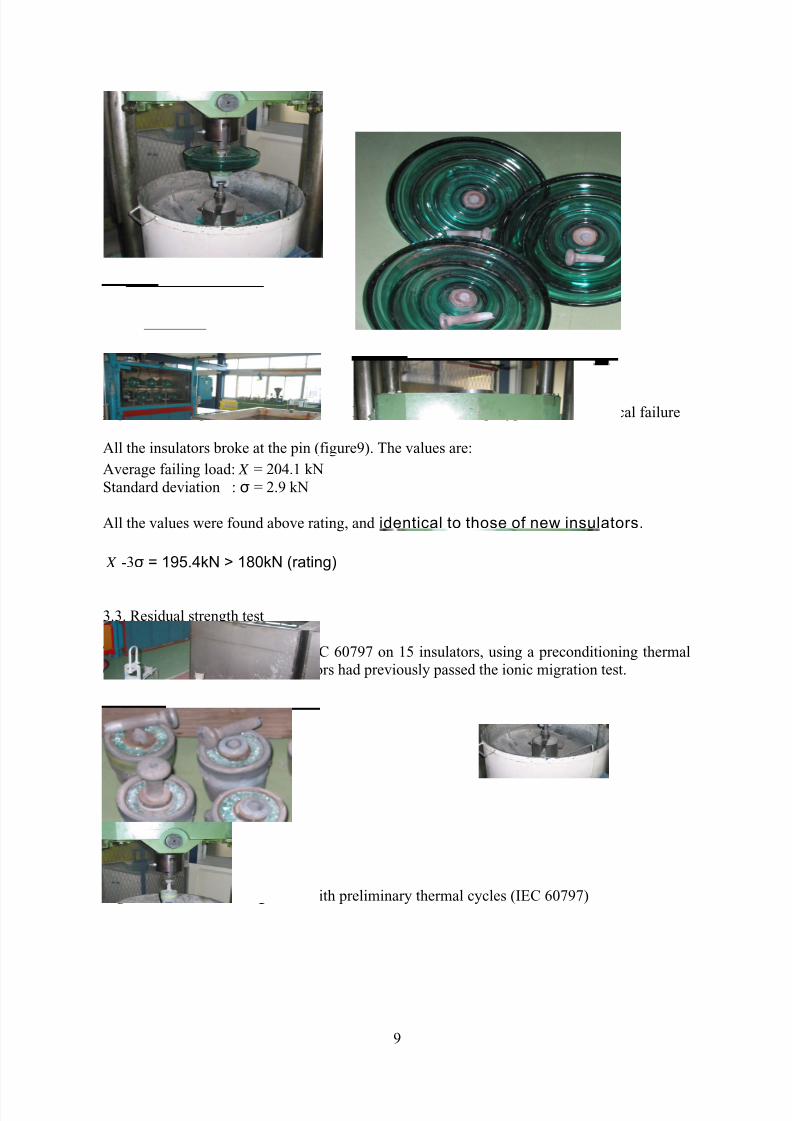
Out of the 15 units tested, 9 insulators broke at the pin. The lowest value of the pin breakage
is 200 kN. For the others, 6 pins were pulled out, the lowest value being 176.1 kN. For these
one, the calculation of the acceptance criteria is:
Average failing load: X = 192.4 kN
Standard deviation: σ = 8.5 kN
The lowest value is at 97.7 % of the rating, far above any standard requirement for this type
of test. The IEC calculation method on the pin pull outs would give the following result:
(0.65*180+1.645* σ) = 196.7 kNk= 0.99
After more than 35 years in service, the residual strength of these insulators is above standard
requirement, and quite equal to the rated value of new and intact insulators.
3.4. Thermo mechanical tests
This test was performed as per IEC 60575 with temperature variations from -50°C to +50°C.
The set up is shown in figure 11. All 10 insulators were taken from the samples which had
passed previously the ionic migration test.
Figure 11: Thermo mechanical test
-50/+50°C
(Saint Yorre laboratory, France)
7/27/2019 ExperiencesInsulators of HVDC Lines in Itaipu-TL
http://slidepdf.com/reader/full/experiencesinsulators-of-hvdc-lines-in-itaipu-tl 11/15
11
After the 96h cycle test, the insulators were pulled to mechanical destruction. All the values
were above rating. (7 broken pins, 3 broken caps)
The results are:
Average failing load: X = 209.1 kNStandard deviation: σ = 10.8 kN
Acceptance criteria: X = 209.1 kN > (1.2*10.8 + 180) = 187.8 kN
These insulators pass successfully the thermo mechanical tests as per IEC 60575 with
reinforced thermal cycle criteria.
As can be seen from all these tests, the insulators which have spent more than 35 years on a
500kV DC line show no sign of ageing either from an electric, mechanical or thermo
mechanical point of view. (It is important to note that all the insulators used in these
mechanical tests had previously been used for a ionic migration test). Thanks to the
homogeneity of glass and complete inertia to time, these insulators did not age and perform
like new insulators.
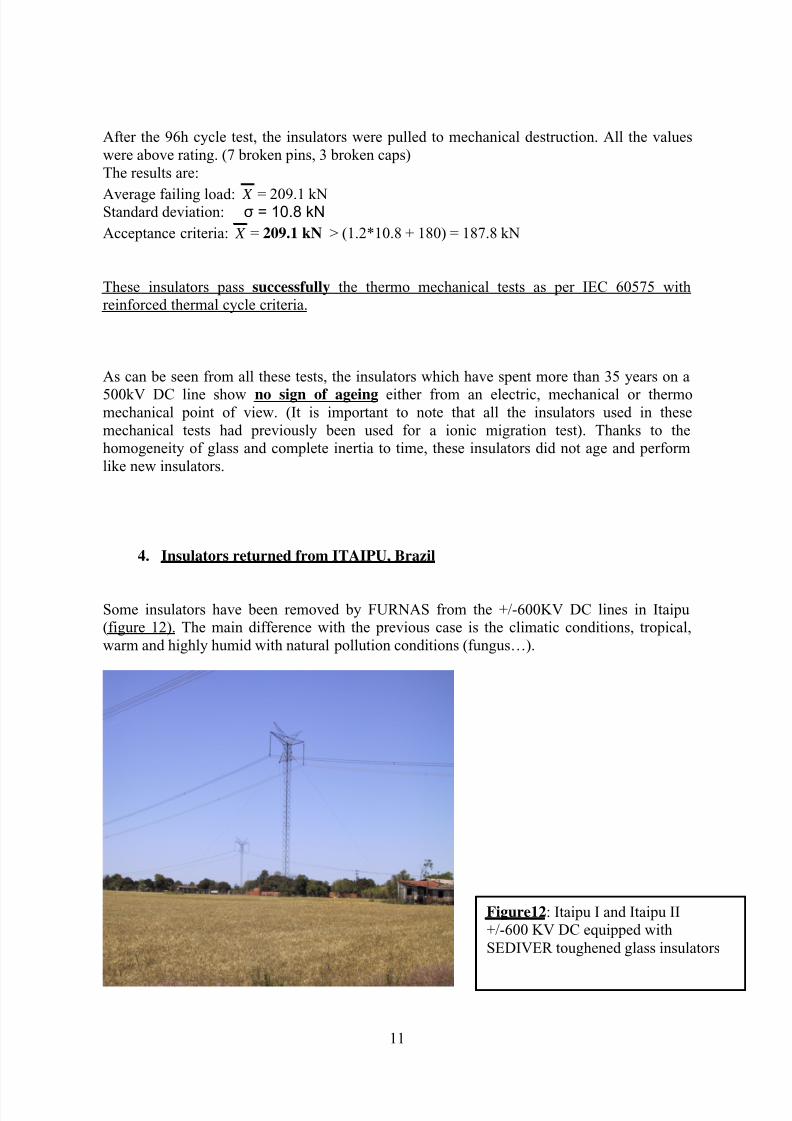
4. Insulators returned from ITAIPU, Brazil
Some insulators have been removed by FURNAS from the +/-600KV DC lines in Itaipu
(figure 12). The main difference with the previous case is the climatic conditions, tropical,
warm and highly humid with natural pollution conditions (fungus…).
Figure12: Itaipu I and Itaipu II
+/-600 KV DC equipped with
SEDIVER toughened glass insulators

7/27/2019 ExperiencesInsulators of HVDC Lines in Itaipu-TL
http://slidepdf.com/reader/full/experiencesinsulators-of-hvdc-lines-in-itaipu-tl 12/15
12
4.1 General comments and observations
These insulators were produced in 1981 and 1986 respectively fro Bipôle I and II. The visual
observations show insulators in very good conditions. Some insulators have rust spots at the
base of the cap, but overall their aspect is excellent. It appears also that the pollution (when present) is not evenly distributed. Some units are very clean others have a biological type of
pollution located mainly between the outer edge of the under skirt and the large rib under the
skirt as shown in figure 13. A close up (figure 14) of the pollution deposit shows fungus in
this region.
Figure 13: pollution concentration in
external section of the bottom of the
insulator outside the large rib while
the rest of the insulator remains clean
Figure 14: close up of biological
pollution built up
7/27/2019 ExperiencesInsulators of HVDC Lines in Itaipu-TL
http://slidepdf.com/reader/full/experiencesinsulators-of-hvdc-lines-in-itaipu-tl 13/15
13
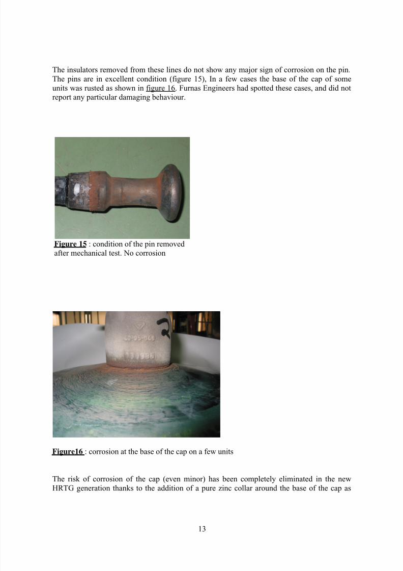
The insulators removed from these lines do not show any major sign of corrosion on the pin.
The pins are in excellent condition (figure 15), In a few cases the base of the cap of some
units was rusted as shown in figure 16. Furnas Engineers had spotted these cases, and did not
report any particular damaging behaviour.
Figure 15 : condition of the pin removed
after mechanical test. No corrosion
Figure16 : corrosion at the base of the cap on a few units
The risk of corrosion of the cap (even minor) has been completely eliminated in the new
HRTG generation thanks to the addition of a pure zinc collar around the base of the cap as

7/27/2019 ExperiencesInsulators of HVDC Lines in Itaipu-TL
http://slidepdf.com/reader/full/experiencesinsulators-of-hvdc-lines-in-itaipu-tl 14/15
14
explained earlier in figures 1 and 2. Such additional protection to the cap has been used since
on several major projects like in India or China.
4.2. Mechanical strength test
These insulators were rated at 160kN. A mechanical test (figure19) was performed on 10
insulators taken from both polarities:
Figure 19: Itaipu insulator during the mechanical test (polarity (-))
Average failing load: X = 216.2 kN
Standard deviation: σ = 12.1 kN
The review of these results is showing that
X -3xσ = 179.9 kN > 160kN (rating)
The mechanical strength of the insulators removed after 20 to 25 years in service is identical
to the performance of new insulators.
(The test program on these insulators is still in progress at the present time. More data will be
available when the study is completed).

7/27/2019 ExperiencesInsulators of HVDC Lines in Itaipu-TL
http://slidepdf.com/reader/full/experiencesinsulators-of-hvdc-lines-in-itaipu-tl 15/15