Embed Size (px)
Citation preview

PRINCIPIA CYBERNETICA ’03 LIBEREC
1
EXPERIENCES AND DEVICES OF R&D LABORATORY OF NOISE AND VIBRATION DIAGNOSTICS AT THE
DEPARTMENT OF CONTROL SYSTEMS & INSTRUMENTATION VŠB-TU OF OSTRAVA
Jiří Tůma, Lubomír Smutný, Petr Kočí
VŠB Technická univerzita Ostrava, Fakulta strojní, Katedra ATŘ Ul. 17. listopadu 15, 408 77 Ostrava
Tel. +420 59 699 3482, E-mail: [email protected], Tel. +420 59 699 3484, E-mail: [email protected],
Tel. +420 59 699 4223, E-mail: [email protected]
Abstract - The paper shows instrumentation by which are equipped labs for diagnostics and experimental dynamics of the Department of Control Systems and Instrumentation, Faculty of Mechanical engineering at Technical university of Ostrava. A special attention is paid to transducers for noise, vibration and RPM measurements, signal conditioning and processing.
Keywords - Diagnostics, experimental dynamics, noise, vibration and RPM measurements, incremental rotary encoders, signal analyser, signal conditioning.
1 Introduction
The Department of Control Systems & Instrumentation is a specialised department of regular master study branches “Automatic Control and Engineering Informatics”, which has the 25-year tradition. The master degree study is directed to areas of dynamic systems, techniques, design and programming of computer integrated manufacturing systems in mechanical engineering. After passing particular specialized exams and defending dissertation thesis the successfully graduated student acquire a Ph.D degree. The education program in the master and Ph.D degree is partly focused to the diagnostics in machinery. The students promote their skills in handling with sensors, transducers and signal analysers. Department labs were equipped by the latest instrumentation originated from BRÜEL&KJÆR and ENDEVCO to support high quality of education. We lay stress on the fact that our student can get the first experience with actual experimental methods in noise, vibration and RPM measurements.
The Department CSI is involved in solving a number of research problems according to the needs of industry in the field of designing and implementation measuring, diagnostics and control systems.
2 Transducers and signal processing instruments
A list of instruments in department labs intended for diagnostics and experimental dynamics is now as follows:
• LabShop PULSE Portable Signal Analyser 4/2 channels, BRÜEL&KJÆR • Charge amplifier NEXUS, BRÜEL&KJÆR • Deltatron Accelerometer 4396, BRÜEL&KJÆR • DeltaTron Accelerometer 4508 B 001 (2 pieces) , BRÜEL&KJÆR • Deltatron Accelerometer 4507, BRÜEL&KJÆR • Triaxial Miniature Accelerometer, high sensitivity, internal electronic Deltatron,
BRÜEL&KJÆR • ENDEVCO 7745A – 1000 Istron EE 0111 – micro-g resolution, near DC response, flat to
0.05 Hz
PRINCIPIA CYBERNETICA ’03 LIBEREC
2
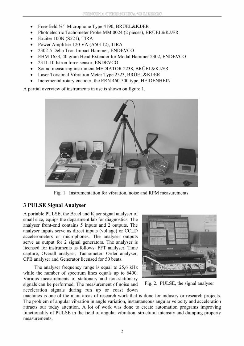
• Free-field ½’’ Microphone Type 4190, BRÜEL&KJÆR • Photoelectric Tachometer Probe MM 0024 (2 pieces), BRÜEL&KJÆR • Exciter 100N (S521), TIRA • Power Amplifier 120 VA (A50112), TIRA • 2302-5 Delta Tron Impact Hammer, ENDEVCO • EHM 1653, 40 gram Head Extender for Modal Hammer 2302, ENDEVCO • 2311-10 Istron force sensor, ENDEVCO • Sound measuring instrument MEDIATOR 2238, BRÜEL&KJÆR • Laser Torsional Vibration Meter Type 2523, BRÜEL&KJÆR • Incremental rotary encoder, the ERN 460-500 type, HEIDENHEIN
A partial overview of instruments in use is shown on figure 1.
3 PULSE Signal Analyser
A portable PULSE, the Bruel and Kjaer signal analyser of small size, equips the department lab for diagnostics. The analyser front-end contains 5 inputs and 2 outputs. The analyser inputs serve as direct inputs (voltage) or CCLD accelerometers or microphones. The analyser outputs serve as output for 2 signal generators. The analyser is licensed for instruments as follows: FFT analyser, Time capture, Overall analyser, Tachometer, Order analyser, CPB analyser and Generator licensed for 50 beats.
The analyser frequency range is equal to 25,6 kHz while the number of spectrum lines equals up to 6400. Various measurements of stationary and non-stationary signals can be performed. The measurement of noise and acceleration signals during run up or coast down machines is one of the main areas of research work that is done for industry or research projects. The problem of angular vibration in angle variation, instantaneous angular velocity and acceleration attracts our today attention. A lot of work was done to create automation programs improving functionality of PULSE in the field of angular vibration, structural intensity and dumping property measurements.
Fig. 2. PULSE, the signal analyser
Fig. 1. Instrumentation for vibration, noise and RPM measurements

PRINCIPIA CYBERNETICA ’03 LIBEREC
3
4 Vibration and RPM measurements
The basic equipments for vibration measurements consist of piezoelectric accelerometers. The charge amplifier NEXUS is intended for 2 piezoelectric and one CCLD (constant current line drive) accelerometers. A photoelectric tachometer probe of BK type MM 0012 or MM 0024 can replace the input for a CCLD accelerometer. One NEXUS input channel is intended for a microphone. The voltage output level, ranging to +/-2 V, can be interfaced to a PC multifunction card. Of cause, it is preferred PULSE to NEXUS.
The acceleration signal can be integrated, even double integrated. The low pass and high pass filtration is an obvious part of signal conditioning. A considerable advantage of the charge amplifier is that it is possible to check signal level during recording a signal.
The simplest method for evaluation of the instantaneous rotational speed is the reciprocal value of the time between two consecutive pulses that are generated by the photoelectric tachometer. The time interval is determined by interpolation some 50 times more accurately than indicated by the actual sampling interval. The accuracy is satisfying for the RPM measurement based on only a pulse per shaft rotation.
5 Torsion vibration measurements
Rotational speed is measured in terms of the number of revolutions per minute (RPM) while the torsion vibration is measured in terms of the angle, angular velocity or angular acceleration. The uniform rotational speed of the constant RPM corresponds to the shaft angle as a linear function of time. The shaft angle as a non-linear time function is associated with the torsion vibration. The rotational speed is obtained as the first derivative of the angle. The torsion vibration can be measured by using rotary incremental encoders, attached to the free end of shaft by a coupling. The encoders produce usually a train of pulses, rather then a sinusoid in the number of thousands per a revolution. In
the case of the large number of pulses and small number of samples per a pulse period, another method based on the phase demodulation is employed. The pulse signal consists of several harmonics of the basic pulse frequency. Each of the harmonic components is the carrier component that can be modulated by varying rotational speed. The phase modulation signal can be derived from the phase of the analytical signal that is
Fig. 4. Incremental rotary encoders, ERN 460-500
Fig. 3. Set of accelerometers and a force transducer
1/order
Circle part
E 1E 2 E 1E 2
order
RMS of Error in radians
+ … 168 RPMx … 635 RPMo …1039 RPM
Fig. 5. Rotary encoder accuracy

PRINCIPIA CYBERNETICA ’03 LIBEREC
4
evaluated using the Hilbert Transform technique. The error level at the distance corresponding to the tooth pitch of the adjacent teeth determines the final accuracy. As it is evident the magnitude of an error at 21 and 44 order is less than 10-5 radians, i.e. approximately 2 angular seconds (see figure 5). The mentioned measurement method was employed to the gear train transmission error measurement that is a quantity in range of angular seconds.
The disadvantage of encoders is that they must be attached to the free end shaft of a machine. In some cases it is impossible or impractical to mount a traditional contact transducer on a rotating object. For making non-contact torsional vibration measurements the department lab is equipped by laser-based Torsional Vibration Meter Type 2523 (see figure 1 and 6). The measurement principle is based on frequency difference of two parallel beams that are reflected from the rotating shaft due to the Doppler phenomenon.
6 Noise level measurements
The noise level measurements are performed by a BK instrument of the 2238 Mediator type (figure 7), which is fitted by a preamplifier and prepolarized ½” free-field condenser microphone. The
main applications are evaluation of environmental noise, measurements of noise at workplaces and assessment of product noise. Mediator's dedicated basic software provides direct support for many applications. The largest level range is equal to 80 dB while the upper range reaches the value of 140 dB and the lower range the value of 80 dB. To maintain the accuracy the sound level calibrator type 4231.
Mediator can be interfaced to a PC via RS 232. It was designed a computer program to transmit measurement data into a PC during measurements.
7 Frequency response measurements using a hammer fitted by the force transducer
Frequency response measurements based on recording an impulse response that is excited by an impact hammer with a tip that is fitted by the piezoelectric force transducer is the most spread identification method for dynamic properties of mechanical structures, especially in the field of modal analysis or identification for the purpose of the automatic control. Firstly both the input and output signal are transferred into the frequency domain using the Fast Fourier Transform, then the frequency transfer function can be evaluated. 8 Stand for absorber testing
A test stand for shock and vibration absorber is built as a tool to do research in the field of non-linear elements and to evaluate their dumping properties. A shaker is powered by an amplifier of 120 W. The PULSE signal generator controls the force acting to the mass via the rubber absorber.
Fig. 6. Laser Torsional Vibration Meter Type 2523
Fig. 7. Mediator
Fig. 8. Impact hammer

PRINCIPIA CYBERNETICA ’03 LIBEREC
5
The acceleration of the shaker moving part and testing mass and force acting between them are recorded by PULSE.
The testing mass is a single degree freedom system. The testing mass is employed to calibrate a force sensor that is placed at the tip of the impact hammer for modal analysis.
Fig. 9. Stand for shock and vibration absorber testing Fig. 10. Mounting a rubber absorber
9 Stand for life testing
The shaker is prepared to serve for life tests of small electronic and mechanic devices. An aluminium platform attached at the shaker for this purpose as it is shown in figure 8. The signal generated by PULSE controls the shaker vibration as in case of the stand for absorber testing. Additionally, a filter can modify the frequency spectrum of controlling signal. On figure 9 we can see the waterfall plot of a multispecterum as a part of signal processing by the Pulse analyser.
10 Software support for signal processing
The teaching and research work in the field of signal processing benefits from the following means
LabShop PULSE Matlab (Signal processing toolbox, Identification toolbox,
Wavelets toolbox) Signal Analyser (Windows based application in VB 6 benefiting from Microsoft Graph
component)
The types of input data, which can be imported into the Signal Analyzer, are shown in following table. To do student’s homework, Signal Analyzer can directly record a data via a sound card. The user can select various parts of the record and save it into the new measurements
Data Source Description
Binary Data arranged in Columns 16 bits data in binary file
Binary Data from Buf-Files Binary data in BUF-file
ASCII Data from Clipboard ASCII data from clipboard
ASCII Data from Text File ASCII data from text file
Waveform File Wave file
Waveform Audio Input Device Data recorded directly from a sound cards
BK 2032 Time Binary data from BK 2034/32 signal analyser
Fig. 8. Platform for life tests

PRINCIPIA CYBERNETICA ’03 LIBEREC
6
Signal Generator Data generated manually or automatically
Each of the input signals can be interfaced to an instrument that list is as follows
Instrument Description
Time Hilbert transform, envelope a filtration in the frequency domain
FFT FFT a filtration in the frequency domain
CPB Averaged 1/1-octave a 1/3-octave frequency spectrum
Autospectrum Averaged autospectrum a filtration in the frequency domain
Cross-Spectrum Averaged cross-spectrum a filtration in the frequency domain
FRF Averaged frequency response a filtration in the frequency domain
Overall Overall level of signal in RMS or PWR
Tachometer RPM evaluated from an impulse signal
Resampling Resampling of signal
Test Unit Unit is only for demonstrating response of the 2-order system
Conclusion
The paper is focused on making the one’s acquaintance with the equipments that is dedicated for education and research in the field of diagnostics and experimental dynamics. The development and innovation of the specialized laboratories is very important goal of R&D projects which are solved with financial support of different agencies as a Grant Agency of Government (GAČR), Agency of Ministry of Education (FR VŠ) and also very important is financial support of industrial enterprises (ŠKODA AUTO Company Mladá Boleslav, etc).
The Laboratory of noise and vibration diagnostics is good example of purposeful action on the Department of Control Systems and Instrumentation and its utilizing creates good conditions for R&D solving.
Acknowledgements
This research has been conducted at the Technical University of Ostrava as a part of the research project No. MSM 272300012 and has been supported also by GAČR as a project No. 102/03/0625. The authors benefit from the research work done for the SKODA Auto Company too.
References
[1] KOČÍ, P. Diagnostic of Machine Tools Dynamic properties. In Proceedings of 3rd International Carpathian Control Conference. Ostrava : VŠB-TU Ostrava, 27. - 30. 5. 2002, p. 575-580. ISBN 80-248-0089-6.
[2] SMUTNÝ, L. Smart Instruments in Wireless LAN. In Proceedings of International Workshop on Intelligent Mining Systems. Fukuoka (Japan): KYUSHU Univer-sity Fukuoka, April 2002, p. 85-90, ISBN 80-86111-90-3
[3] TŮMA, J., KOČÍ, P., ŠKUTA, J., JURÁK, M. Analysis of a car burst shaking while the car engine is running at idle. In Proceedings of 3rd International Carpa-thian Control Conference. Ostrava : VŠB-TU Ostrava, 27. - 30. 5. 2002, s. 105-110. ISBN 80-248-0089-6.