Embed Size (px)
Citation preview
THE AMERICAN SOCIETY OF MECHANICAL ENGINEERS345 E. 47 St., New York, N.Y. 10017
E C The Society shall not be responsible for statements or opinions advanced in papers or inrJ discussion at meetings of the Society or of its Divisions or Sections, or printed in its
M publications. Discussion is printed only if the paper is published in an ASME Journal.^( Released for general publication upon presentation. Full credit should be given to ASME,
the Technical Division, and the author(s). Papers are available from ASME for nine monthsafter the meeting.Printed in USA.
82-GT-57
Experience with Large GasA. Lienert
Turbine Combustion ChambersDepartment Manager Large gas turbine combustion chambers, being arranged outside of the unit, exhibit
quite a lot of advantages with respect to combustion. Moreover, they are charac-0. Schmoch terized by a long life of all components. Thus, in case of such gas turbine units the
Subdivision Manager maintenance and inspection intervals are relatively large being not determined bythe combustion chamber or combustion chamber components. There are not many
Gas Turbine Technology, failures. They may easily be recognized at their initial stage and can be eliminatedMechanical Design, quickly as the inside is accessible via a manhole. This in turn has a positive effect on
Kraftwerk Union AG, West Germany overall maintenance and service cost. Besides, this easy accessibility allows for adirect examination of the turbine inner casing and the first turbine stages in case ofmaintenanced works. Experiences are based on the operation of more than 100 gasturbines of such a kind, whereby several have been run at peak load with more than5000 starts, others at base load with more than 100,000 operating hours.
DESIGN PHILOSOPHY OF THE KWU SILO COMBUSTOR
Companies that prefer large combustion cham-bers in the construction of gas turbines considerthis to be a simple and expedient solution tomeeting the demands for robust and low-mainte-nance equipment for power plant operation. Thesedemands are especially high as concerns the ser-vice life of those components that are subject tosevere stresses when the turbine is run in con-tinuous or, even more so, in peak-load operationwith frequent start-ups.
Further to the usual requirements as regardsthe quality of combustion, the combustion cham-bers must satisfy even more exacting demands:
- Long service life of all components and thushigh reliability in peak and base load oper-ation.
- Long intervals between inspections and henceno adverse influence on the availability ofthe plant.
- Ease of inspection and repair, with conse-quent reduction in maintenance costs.
- Suitability for combustion of a wide rangeof gaseous and liquid fuels without signifi-cant design changes.
- Low pressure losses.
Past experience has shown that these re-quirements can best be realised by the use oflarge combustion chambers.
In the following, an account will be givenof the experience gained by Kraftwerk Union fromthe manufacture of large combustion chambers overa period of more than 25 years.
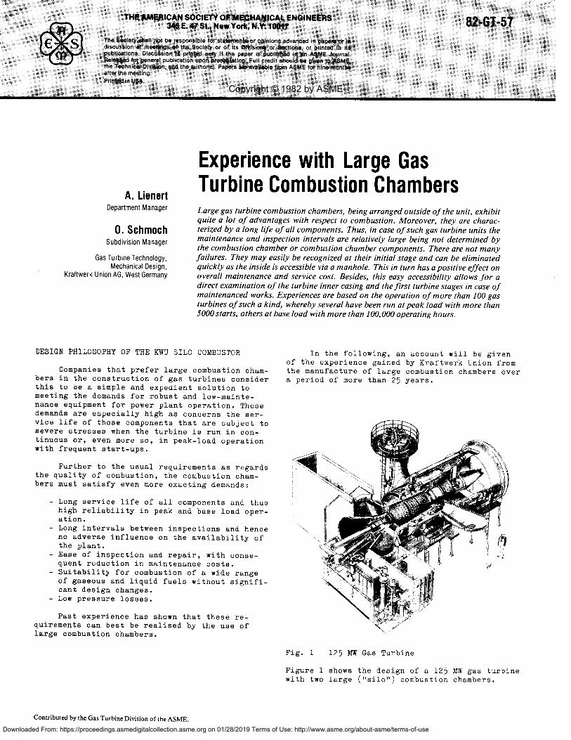
Fig. 1 125 MW Gas Turbine
Figure 1 shows the design of a 125 MW gas turbinewith two large ("silo") combustion chambers.
Contributed by the Gas Turbine Division of the ASME.
Copyright © 1982 by ASME
Downloaded From: https://proceedings.asmedigitalcollection.asme.org on 01/28/2019 Terms of Use: http://www.asme.org/about-asme/terms-of-use
Parameters DimensionKWU-Gas turbine-Type
V82 V93 V94
Combustor pressure pc bar 6.9 9.4 10.0
Combustor inlet air temp. t1 °C 252 30S 314
Combustor outlet gas temp. t2 °C 820 920 1015
Heat input of one combustor MW 66 120 191
Specific heat flow 3895 5211 5250ml bReference velocity mis 11 18 18
Reference residence time 2)in the flame
s 0.10 0.10 0.10
Number of burners per CC 3 6 8
Flame tube diameter mm 1780 1780 2200
Fuel No2-GTFuelOil,Crude Oil,Residual and Natural Gas
Method of fuel atomization Pressure atomization
3
2
1___
p= 12 bartW=700 C
t o =300° C
Z = 20
0,5 1,0 1,5 2,00, meter
kW/m 2
1000 -
800
600
400
200
DESIGN CHARACTERISTICS OF THE SILO COMBUSTOR
For design reasons, KWU decided to releasethe motive heat for the turbine within two largesilo combustors arranged one on either side ofthe turbine. Each of these combustors could, inprincipal, be operated on only one burner. It wasdeemed expedient, however, to install a number ofsmall burners in each combustor, for the follow-ing reasons:
- because of the lower heating capacity of thesmaller burners, the flames are shorter thanthat of a single burner of correspondinglyhigh power
- it is possible to attain a satisfactory tem-perature distribution ahead of the bladingwithin a shorter mixing zone, because thetemperature peaks are less broad and can bebetter dissipated
- the development costs are low- experience gained from smaller test facili-
ties can be readily applied to larger ones- the emission of soot and NO x can be reducedto a lower level if several small burnersare used than if there is only one largeburner
- similar burners can be used for plants ofdifferent ratings; only the number of bur-ners per combustor need be varied.
The design of large combustion chambers thatare not integrated into the machine imposes norestrictions as regards length and diameter. Ifmore burners are installed, the machine must bemade wider but this has no influence on the flamelength and therefore no effect on the length ofthe combustor.
This keeps the gas velocities low and facili-tates fulfilment of the following design condi-tions:
- temperature differences within the hot gasflow ahead of the turbine as small as possi-ble;
- homogenous flow without eddies to the firstturbine blading stage;
- adequate cooling of the components carryinghot gases facilitated by suitable matchingof the cross-sections of the air- and hotgas channels.
Some essential design data for the combustors arelisted in table 1.
LINER HEAT LOAD
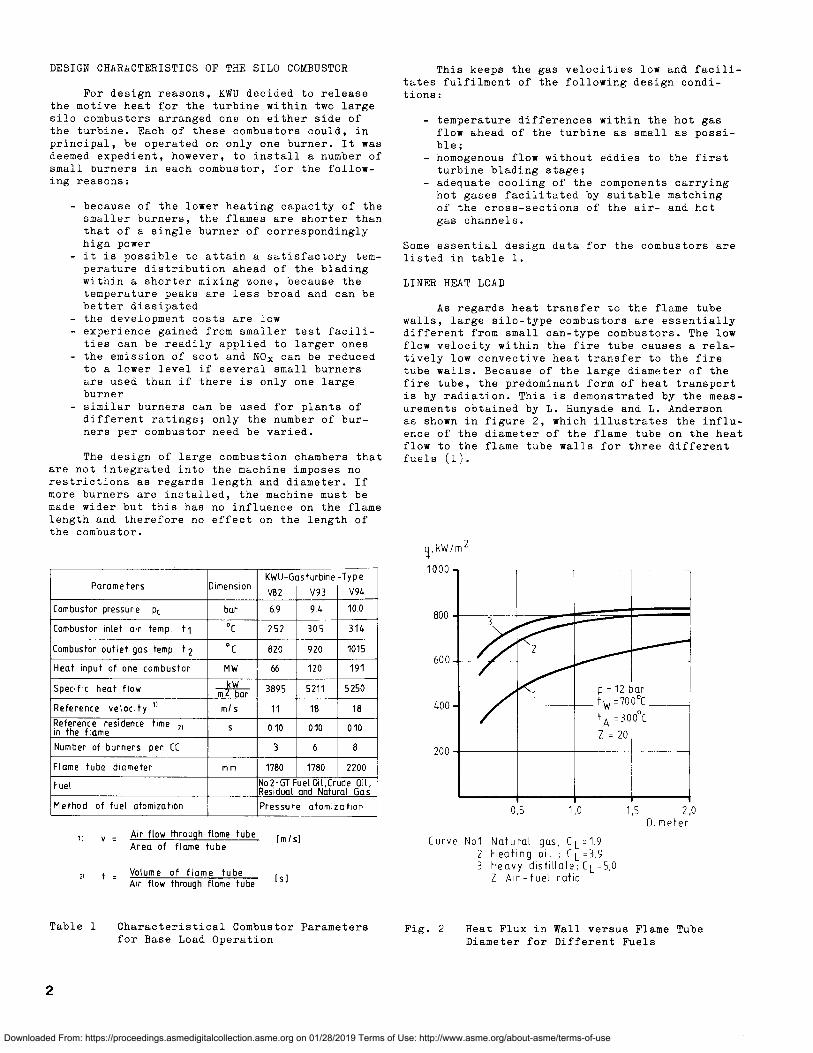
As regards heat transfer to the flame tubewalls, large silo-type combustors are essentiallydifferent from small can-type combustors. The lowflow velocity within the fire tube causes a rela-tively low convective heat transfer to the firetube walls. Because of the large diameter of thefire tube, the predominant form of heat transportis by radiation. This is demonstrated by the meas-urements obtained by L. Hunyade and L. Andersonas shown in figure 2, which illustrates the influ-ence of the diameter of the flame tube on the heatflow to the flame tube walls for three differentfuels (1).
ii v-
Air flow through flame tube (mis]Area of flame tube
2 t = Volume of flame tube Is]Air flow through flame tube
Table 1 Characteristical Combustor Parametersfor Base Load Operation
Curve Not Natural gus; CL =192 Heating oil , CL=3,93 Heavy distillate; CL=5,0
Z Air-fuel ratio
Fig. 2 Heat Flux in Wall versus Flame TubeDiameter for Different Fuels
N
Downloaded From: https://proceedings.asmedigitalcollection.asme.org on 01/28/2019 Terms of Use: http://www.asme.org/about-asme/terms-of-use
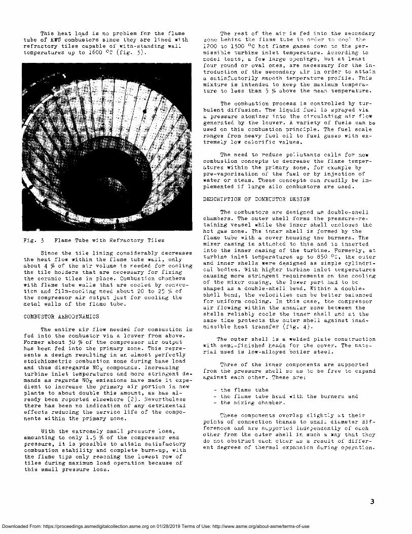
This heat load is no problem for the flametube of KWU combustors since they are lined withrefractory tiles capable of with-standing walltemperatures up to 1600 °C (fig. 3).
Fig. 3 Flame Tube with Refractory Tiles
Since the tile lining considerably decreasesthe heat flow within the flame tube wall, onlyabout 4 % of the air volume is needed for coolingthe tile holders that are necessary for fixingthe ceramic tiles in place. Combustion chamberswith flame tube walls that are cooled by convec-tion and film-cooling need about 20 to 25 % ofthe compressor air output just for cooling themetal walls of the flame tube.
COMBUSTOR AERODYNAMICS
The entire air flow needed for combustion isfed into the combustor via a louver from above.Former about 30 % of the compressor air outputhas been fed into the primary zone. This repre-sents a design resulting in an almost perfectlystoichiometric combustion zone during base loadand thus disregards NO compounds. Increasingturbine inlet temperatures and more stringent de-mands as regards NOx emissions have made it expe-dient to increase the primary air portion in newplants to about double this amount, as has al-ready been reported elsewhere (2). Neverthelessthere has been no indication of any detrimentaleffects reducing the service life of the compo-nents within the primary zone.
With the extremely small pressure loss,amounting to only 1.5 % of the compressor endpressure, it is possible to attain satisfactorycombustion stability and complete burn-up, withthe flame tips only reaching the lowest row oftiles during maximum load operation because ofthis small pressure loss.
The rest of the air is fed into the secondaryzone behind the flame tube in order to cool the1200 to 1300 °C hot flame gases down to the per-missible turbine inlet temperature. According tomodel tests, a few large openings, but at leastfour round or oval ones, are necessary for the in-troduction of the secondary air in order to attaina satisfactorily smooth temperature profile. Thismixture is intended to keep the maximum tempera-ture to less than 5 % above the mean temperature.
The combustion process is controlled by tur-bulent diffusion. The liquid fuel is sprayed viaa pressure atomizer into the circulating air flowgenerated by the louver. A variety of fuels can beused on this combustion principle. The fuel scaleranges from heavy fuel oil to fuel gases with ex-tremely low calorific values.
The need to reduce pollutants calls for newcombustion concepts to decrease the flame temper-atures within the primary zone, for example bypre-vaporization of the fuel or by injection ofwater or steam. These concepts can readily be im-plemented if large silo combustors are used.
DESCRIPTION OF COMBUSTOR DESIGN
The combustors are designed as double-shellchambers. The outer shell forms the pressure-re-taining vessel while the inner shell encloses thehot gas zone. The inner shell is formed by theflame tube with a cover housing the burners. Themixer casing is attached to this and is insertedinto the inner casing of the turbine. Formerly, atturbine inlet temperatures up to 850 °C, the outerand inner shells were designed as simple cylindri-cal bodies. With higher turbine inlet temperaturescausing more stringent requirements on the coolingof the mixer casing, the lower part had to beshaped as a double-shell bend. Within a double-shell bend, the velocities can be better balancedfor uniform cooling. In this case, the compressorair flowing within the annular zone between theshells reliably cools the inner shell and at thesame time protects the outer shell against inad-missible heat transfer (fig. 4).
The outer shell is a welded plate constructionwith semi-finished heads for the cover. The mate-rial used is low-alloyed boiler steel.
Three of the inner components are supportedfrom the pressure shell so as to be free to expandagainst each other. These are:
- the flame tube- the flame tube head with the burners and- the mixing chamber.
These components overlap slightly at theirpoints of connection thanks to small diameter dif-ferences and are supported independently of eachother from the outer shell in such a way that theydo not obstruct each other as a result of differ-ent degrees of thermal expansion during operation.
3
Downloaded From: https://proceedings.asmedigitalcollection.asme.org on 01/28/2019 Terms of Use: http://www.asme.org/about-asme/terms-of-use
illIII
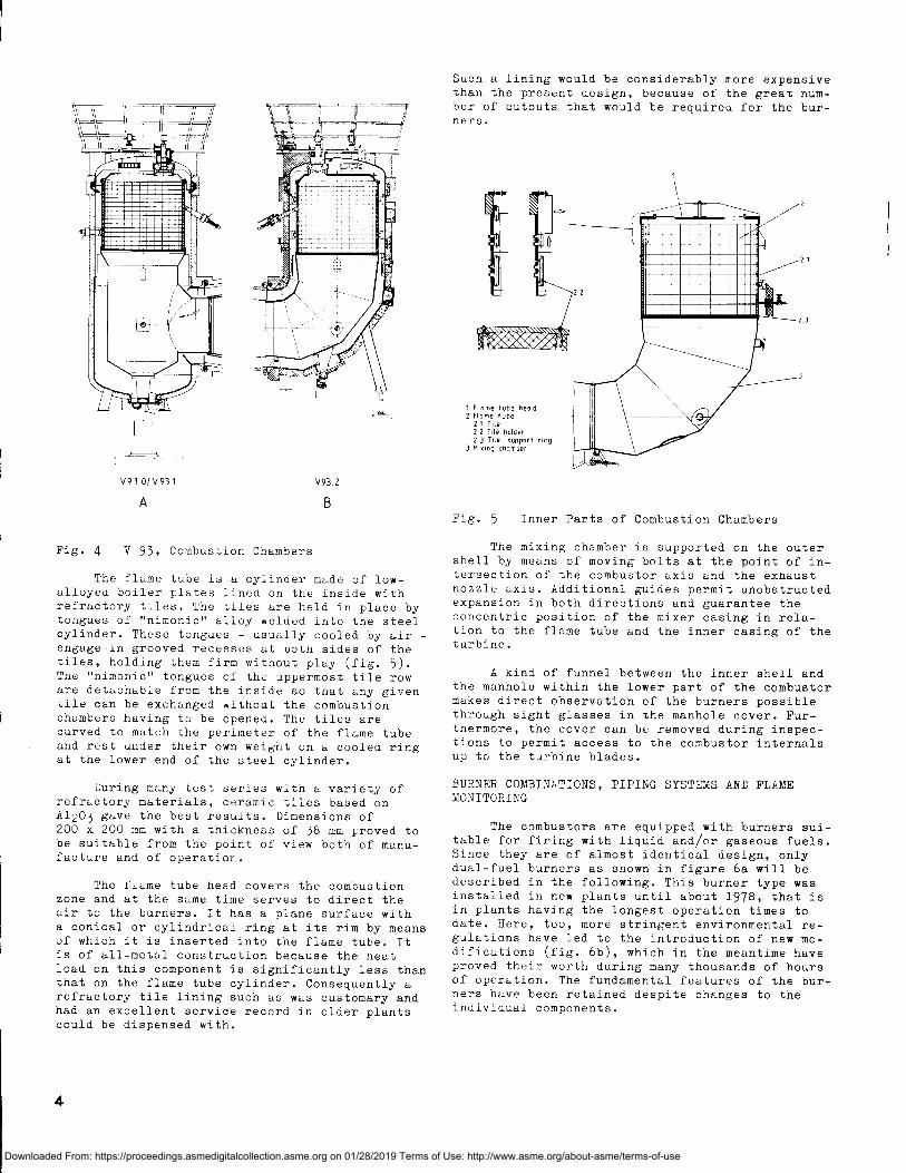
1 Flame tube dead2. Flame tube
21 Tile2 2 Tile "older2.3 Tile napped ring
3 Mixing chamber
Such a lining would be considerably more expensivethan the present design, because of the great num-ber of cutouts that would be required for the bur-ners.
V93 O/V931 V93 2
A B
Fig. 4 V 93, Combustion Chambers
The flame tube is a cylinder made of low-alloyed boiler plates lined on the inside withrefractory tiles. The tiles are held in place bytongues of "nimonic" alloy welded into the steelcylinder. These tongues - usually cooled by airengage in grooved recesses at both sides of thetiles, holding them firm without play (fig. 5).The "nimonic" tongues of the uppermost tile roware detachable from the inside so that any giventile can be exchanged without the combustionchambers having to be opened. The tiles arecurved to match the perimeter of the flame tubeand rest under their own weight on a cooled ringat the lower end of the steel cylinder.
During many test series with a variety ofrefractory materials, ceramic tiles based onAl203 gave the best results. Dimensions of200 x 200 mm with a thickness of 38 mm proved tobe suitable from the point of view both of manu-facture and of operation.
The flame tube head covers the combustionzone and at the same time serves to direct theair to the burners. It has a plane surface witha conical or cylindrical ring at its rim by meansof which it is inserted into the flame tube. Itis of all-metal construction because the heatload on this component is significantly less thanthat on the flame tube cylinder. Consequently arefractory tile lining such as was customary andhad an excellent service record in older plantscould be dispensed with.
Fig. 5 Inner Parts of Combustion Chambers
The mixing chamber is supported on the outershell by means of moving bolts at the point of in-tersection of the combustor axis and the exhaustnozzle axis. Additional guides permit unobstructedexpansion in both directions and guarantee theconcentric position of the mixer casing in rela-tion to the flame tube and the inner casing of theturbine.
A kind of funnel between the inner shell andthe manhole within the lower part of the combustormakes direct observation of the burners possiblethrough sight glasses in the manhole cover. Fur-thermore, the cover can be removed during inspec-tions to permit access to the combustor internalsup to the turbine blades.
BURNER COMBINATIONS, PIPING SYSTEMS AND FLAMEMONITORING
The combustors are equipped with burners sui-table for firing with liquid and/or gaseous fuels.Since they are of almost identical design, onlydual-fuel burners as shown in figure 6a will bedescribed in the following. This burner type wasinstalled in new plants until about 1978, that isin plants having the longest operation times todate. Here, too, more stringent environmental re-gulations have led to the introduction of new mo-difications (fig. 6b), which in the meantime haveproved their worth during many thousands of hoursof operation. The fundamental features of the bur-ners have been retained despite changes to theindividual components.
4
Downloaded From: https://proceedings.asmedigitalcollection.asme.org on 01/28/2019 Terms of Use: http://www.asme.org/about-asme/terms-of-use
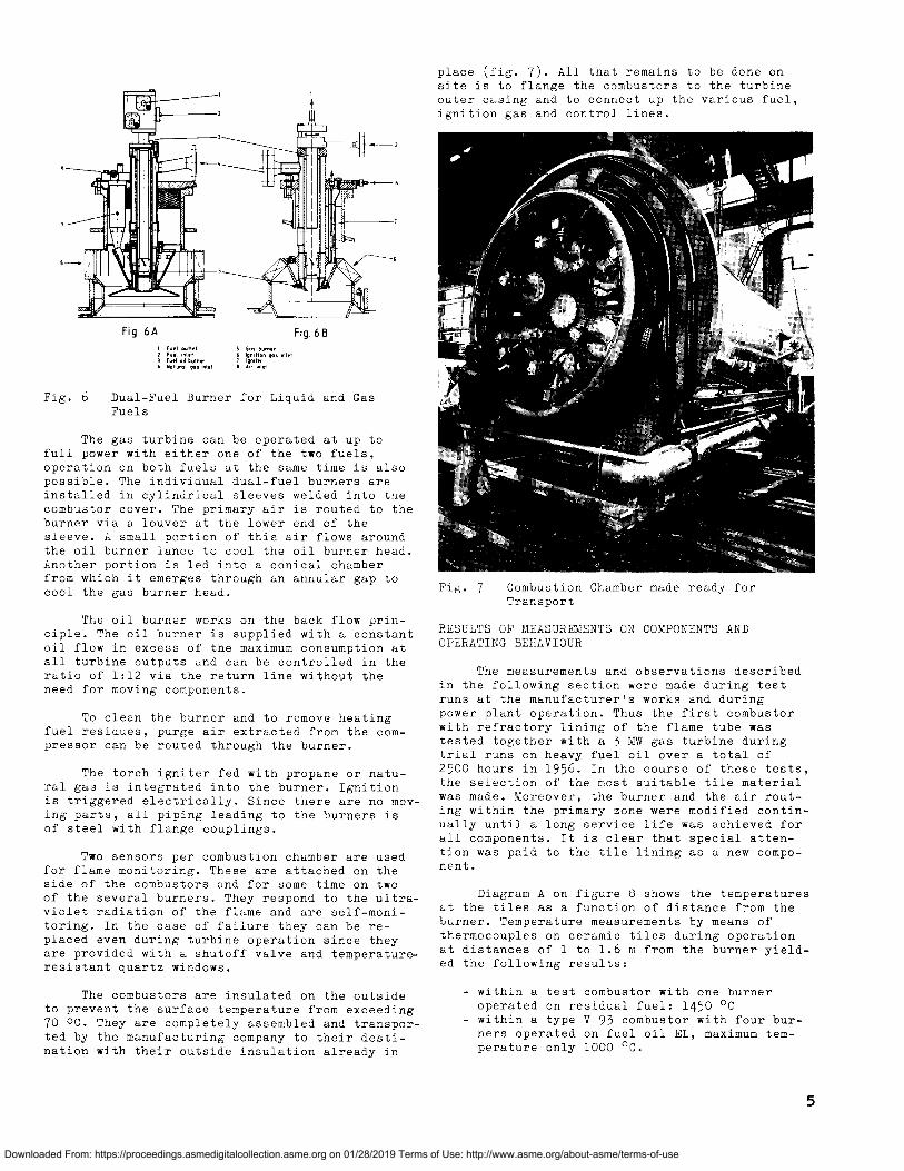
Fig. 7 Combustion Chamber made ready forTransport
Fig. 6A Fig. 6BI Fa.l , tI.f 5 Gas burnerZ Fuel inlet 6 Ignition gas inlet3 F..1 oIl burner i Igni hr
Natural gas .1.1 1 AS .1.1
Fig. 6 Dual-Fuel Burner for Liquid and GasFuels
The gas turbine can be operated at up tofull power with either one of the two fuels,operation on both fuels at the same time is alsopossible. The individual dual-fuel burners areinstalled in cylindrical sleeves welded into thecombustor cover. The primary air is routed to theburner via a louver at the lower end of thesleeve. A small portion of this air flows aroundthe oil burner lance to cool the oil burner head.Another portion is led into a conical chamberfrom which it emerges through an annular gap tocool the gas burner head.
The oil burner works on the back flow prin-ciple. The oil burner is supplied with a constantoil flow in excess of the maximum consumption atall turbine outputs and can be controlled in theratio of 1:12 via the return line without theneed for moving components.
To clean the burner and to remove heatingfuel residues, purge air extracted from the com-pressor can be routed through the burner.
The torch igniter fed with propane or natu-ral gas is integrated into the burner. Ignitionis triggered electrically. Since there are no mov-ing parts, all piping leading to the burners isof steel with flange couplings.
Two sensors per combustion chamber are usedfor flame monitoring. These are attached on theside of the combustors and for some time on twoof the several burners. They respond to the ultra-violet radiation of the flame and are self-moni-toring. In the case of failure they can be re-placed even during turbine operation since theyare provided with a shutoff valve and temperature-resistant quartz windows.
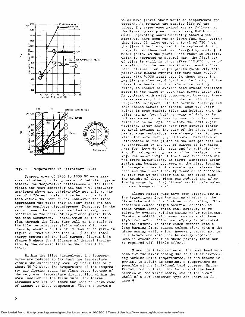
The combustors are insulated on the outsideto prevent the surface temperature from exceeding70 °C. They are completely assembled and transpor-ted by the manufacturing company to their desti-nation with their outside insulation already in
place (fig. 7). All that remains to be done onsite is to flange the combustors to the turbineouter casing and to connect up the various fuel,ignition gas and control lines.
RESULTS OF MEASUREMENTS ON COMPONENTS ANDOPERATING BEHAVIOUR
The measurements and observations describedin the following section were made during testruns at the manufacturer's works and duringpower plant operation. Thus the first combustorwith refractory lining of the flame tube wastested together with a 3 MW gas turbine duringtrial runs on heavy fuel oil over a total of2500 hours in 1956. In the course of these tests,the selection of the most suitable tile materialwas made. Moreover, the burner and the air rout-ing within the primary zone were modified contin-ually until a long service life was achieved forall components. It is clear that special atten-tion was paid to the tile lining as a new compo-nent.
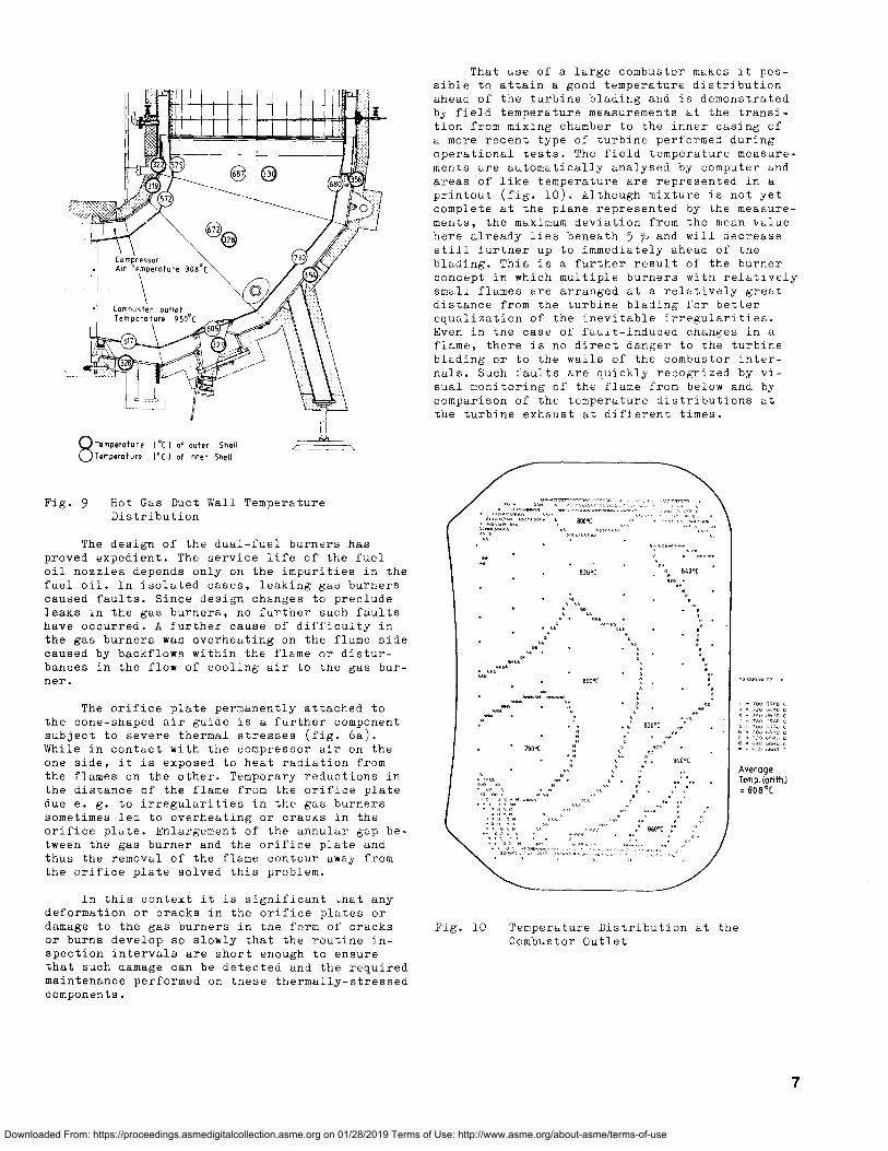
Diagram A on figure 8 shows the temperaturesat the tiles as a function of distance from theburner. Temperature measurements by means ofthermocouples on ceramic tiles during operationat distances of 1 to 1.6 m from the burner yield-ed the following results:
- within a test combustor with one burneroperated on residual fuel: 1450 °C
- within a type V 93 combustor with four bur-ners operated on fuel oil EL, maximum tem-perature only 1000 ° C.
5
Downloaded From: https://proceedings.asmedigitalcollection.asme.org on 01/28/2019 Terms of Use: http://www.asme.org/about-asme/terms-of-use
1300
1200
z 1100
1000 2 F
A E 9002 GT V93 (Four burners, Fuel No2-0TI
!; 800 part load
N7no
E 600 3
500 6
400
0,4 0,6 0,8 1,0 1Distonce from burner Iml
./ice rl^^ Q
Iu'4P '^^Ii^
► '
Fig. 8 Temperature in Refractory Tiles
Temperatures of 1200 to 1300 °C were mea-sured at other plants by means of radiation pyro-meters. The temperature differences at the tileswithin the test combustor and the V 93 combustormentioned above are attributable not only to theuse of different fuels but rather to the factthat within the four burner combustor the flameapproaches the tiles only at four spots and notover the complete circumference. Moreover, in thesecond case, the burners used had already beenmodified on the basis of experience gained fromthe test combustor. A calculation of the heatflux through the flame tube wall on the basis ofthe tile temperatures yields values which arelower by about a factor of 10 than those given infigure 2. That is less than 0.1 % of the totalenergy content of the fuel burned. Diagram B infigure 8 shows the influence of thermal insula-tion by the ceramic tiles on the flame tubeshell.
Within the tiles themselves, the tempera-tures are reduced so far that the temperaturewithin the surrounding steel cylinder lies onlyabout 30 °C above the temperature of the compres-sor air flowing round the flame tube. Because ofthe very even temperature distribution within thesteel section of the flame tube, the thermalstresses are low and there has been no known caseof damage to these components. Thus the ceramic
tiles have proved their worth as temperature pro-tection. As regards the service life of thetiles, the experience gained was as follows: atthe German power plant Braunschweig North about26,000 operating hours including about 4,500start-ups have been run on light fuel oil. Duringthis time, 12 tiles out of a total of 720 fromthe flame tube lining had to be replaced duringinspections; these had been damaged by scaling ofmetal parts. At the plant "Hohe Wand" in Austria,which is operated on natural gas, the first setof tiles is still in place after 115,000 hours ofoperation. In the meantime similar results havebeen obtained from larger plants (.50 MW), withparticular plants running for more than 50,000hours with 3,000 start-ups. In these cases theresults are also valid for the tile lining of theflame tube heads. In the case of refractorytiles, it cannot be avoided that cracks sometimesoccur in the tiles or even that pieces break off.By contrast with metal components, however, thesepieces are very brittle and shatter into tinyfragments on impact with the turbine blading, andthus cannot damage the blades. Wear was ascer-tained in some ceramic tiles and holders when thetiles had not been held by means of deformableholders so as to be free to move. In a few casestiles had to be replaced before the next majorrevision. After change-over from ceramic liningto metal designs in the case of the flame tubeheads, some combustors have already been in oper-ation for more than 50,000 hours. Inadmissibledeformation of the plates on the hot gas side canbe controlled by the use of plates of low thick-ness for these double heads and by suitable dos-ing of cooling air by means of baffle-type cool-ing. The outer rings of the flame tube heads didnot prove satisfactory at first. Sometimes defor-mation and burning occurred at the rims, leadingto irregularities in the annular gap between thehead and the flame tube. By means of an addition-al tile row at the upper end of the flame tube,the height of these rings was reduced and afterthe introduction of additional cooling air holesno more damage occurred.
Slight radial gaps have been allowed for atthe transitions from the mixing chamber to theflame tube and to the turbine inner casing. Thissometimes causes slight material abrasion atthese transitions, which can, however, be re-paired by overlay welding during major revisions.Thanks to additional corrections made at thesegaps, further abrasion can largely be precludedfor the future. In other cases burners with along burning flame caused deformations within themixer casing wall, which, however, proved not tobe a hazard and which can be easily repaired.Even if cracks occur at these points, these canbe repaired with little effort.
Since the introduction of the pure bend ver-sion for the mixer casing due to further increas-ing turbine inlet temperatures, it has become im-portant to attain as constant a temperature aspossible at the individual bend courses. Satis-factory temperature distributions at the bendsection of the mixer casing and of the outershell of a new combustor type are shown in fi-gure 9.
6
Downloaded From: https://proceedings.asmedigitalcollection.asme.org on 01/28/2019 Terms of Use: http://www.asme.org/about-asme/terms-of-use
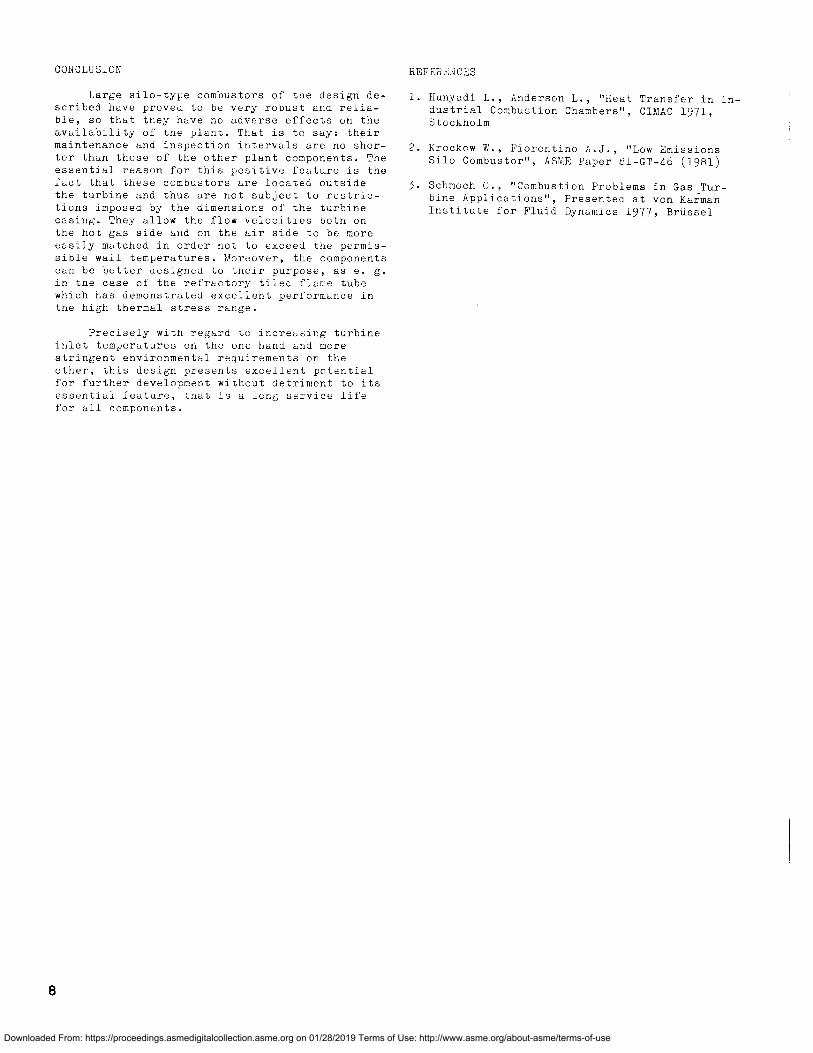
That use of a large combustor makes it pos-sible to attain a good temperature distributionahead of the turbine blading and is demonstratedby field temperature measurements at the transi-tion from mixing chamber to the inner casing ofa more recent type of turbine performed duringoperational tests. The field temperature measure-ments are automatically analysed by computer andareas of like temperature are represented in aprintout (fig. 10). Although mixture is not yetcomplete at the plane represented by the measure-ments, the maximum deviation from the mean valuehere already lies beneath 5 o and will decreasestill further up to immediately ahead of theblading. This is a further result of the burnerconcept in which multiple burners with relativelysmall flames are arranged at a relatively greatdistance from the turbine blading for betterequalization of the inevitable irregularities.Even in the case of fault-induced changes in aflame, there is no direct danger to the turbineblading or to the walls of the combustor inter-nals. Such faults are quickly recognized by vi-sual monitoring of the flame from below and bycomparison of the temperature distributions atthe turbine exhaust at different times.
687 ®3
0\ 67z
28
CompressorAir Temperature 30B ° C
Combuster outletTemperature 950° C ,_
8 Temperature 1 °C I of outer ShellTemperature 1 ° C) of inner Shell
Fig. 9 Hot Gas Duct Wall TemperatureDistribution
The design of the dual-fuel burners hasproved expedient. The service life of the fueloil nozzles depends only on the impurities in thefuel oil. In isolated cases, leaking gas burnerscaused faults. Since design changes to precludeleaks in the gas burners, no further such faultshave occurred. A further cause of difficulty inthe gas burners was overheating on the flame sidecaused by backflows within the flame or distur-bances in the flow of cooling air to the gas bur-ner.
The orifice plate permanently attached tothe cone-shaped air guide is a further componentsubject to severe thermal stresses (fig. ba).While in contact with the compressor air on theone side, it is exposed to heat radiation fromthe flames on the other. Temporary reductions inthe distance of the flame from the orifice platedue e. g. to irregularities in the gas burnerssometimes led to overheating or cracks in theorifice plate. Enlargement of the annular gap be-tween the gas burner and the orifice plate andthus the removal of the flame contour away fromthe orifice plate solved this problem.
In this context it is significant that anydeformation or cracks in the orifice plates ordamage to the gas burners in the form of cracksor burns develop so slowly that the routine in-spection intervals are short enough to ensurethat such damage can be detected and the requiredmaintenance performed on these thermally-stressedcomponents.
•• 820°C 840°C
4ta Boo°(
820 -C
780°C
B40°CAverageTemp. (arithi= 808 ° C
M .. B60°C
Fig. 10 Temperature Distribution at theCombustor Outlet
7
Downloaded From: https://proceedings.asmedigitalcollection.asme.org on 01/28/2019 Terms of Use: http://www.asme.org/about-asme/terms-of-use
CONCLUSION
Large silo-type combustors of the design de-scribed have proved to be very robust and relia-ble, so that they have no adverse effects on theavailability of the plant. That is to say: theirmaintenance and inspection intervals are no shor-ter than those of the other plant components. Theessential reason for this positive feature is thefact that these combustors are located outsidethe turbine and thus are not subject to restric-tions imposed by the dimensions of the turbinecasing. They allow the flow velocities both onthe hot gas side and on the air side to be moreeasily matched in order not to exceed the permis-sible wall temperatures. Moreover, the componentscan be better designed to their purpose, as e. g.in the case of the refractory tiled flame tubewhich has demonstrated excellent performance inthe high thermal stress range.
Precisely with regard to increasing turbineinlet temperatures on the one hand and morestringent environmental requirements on theother, this design presents excellent potentialfor further development without detriment to itsessential feature, that is a long service lifefor all components.
HHFERLNCES
Hunyadi L., Anderson L., "Heat Transfer in In-dustrial Combustion Chambers", CIMAC 1971,Stockholm
2. Krockow 1J., Fiorentino A.J., "Low EmissionsSilo Combustor", ASME Paper 61-GT -46 (1981)
3. Schmoch 0., "Combustion Problems in Gas Tur-bine Applications", Presented at von KarmanInstitute for Fluid Dynamics 1977, Brussel
N.
Downloaded From: https://proceedings.asmedigitalcollection.asme.org on 01/28/2019 Terms of Use: http://www.asme.org/about-asme/terms-of-use