Embed Size (px)
Citation preview
Expansion Joints – Engineering Guide
Fabric expansion joints for ducting systems
ESA Publication No. 011/09 (revision 2 of publication 011/01)
2009 September

This page is left blank intentionally
1
ESA Publication No. 011/09 (revision 2 of publication 011/01)
Expansion Joints – Engineering Guide
Fabric expansion joints for ducting systems
Revision 1 contains change of address details for the ESA
Revision 2 contains amendments to section 13.4 on Conversion factors (SI units)
This document is the copyright © 2009 of the European Sealing Association (ESA).
All rights reserved.
Members of the ESA may copy this document as required.
No part of this publication may be reproduced in any form by non-members without prior written permission of the ESA.
European Sealing Association Tegfryn Tregarth Gwynedd LL57 4PL United Kingdom ℡ : +44 1248 600 250 Fax: +44 1248 600 250 www.europeansealing.com
2
This document is published by the European Sealing Association (ESA), sponsored by the ESA Expansion Joints Division, on behalf of the Members of the Association. The European Sealing Association is a pan-European organisation, established in 1992 and representing a strong majority of the fluid sealing market in Europe. Member Companies are involved in the manufacture and supply of sealing materials, crucial components in the safe containment of fluids during processing and use. Leading manufacturers have joined together to form the Expansion Joints Division of the ESA, to serve industry better and to expand technology in the area of the proper application of these products. Membership of the Division requires:
- a good track record in the industry (including trading for at least 5 years under the same company identity) - operation according to good business practices and ethics - ISO 9000 accreditation or an equivalent accepted quality scheme
All Members of the ESA Expansion Joints Division commit to working according to the principles and requirements as indicated in this Engineering Guide. For an up to date list of Members, please refer to the Expansion Joints Division page of the ESA web site on www.europeansealing.com (the Division page is located within “Organisation”, under “Divisions”)
Acknowledgements The ESA is pleased to recognise the co-operation of Member Companies and others in the preparation of this document, notably the Members of the ESA Expansion Joints Division (for a list of Members, please refer to the ESA website). Without their support, this document would not have been possible. Thanks go especially to:
Phil Cope Derek Davidson Brian S Ellis Bill Evans Ben Foulkes Hans V Hansen Mogens Lindholm Hansen Volker Heid Mike Ingle Harald Poppke Stefan Puchtler Adrian Wakefield
The ESA is also pleased to acknowledge the co-operation of the Fluid Sealing Association (FSA) and the RAL Quality Assurance Association in the development of this publication. In particular, certain sections in this document are adapted from earlier or existing FSA or RAL publications, and these are acknowledged where appropriate. Most of the challenges associated with sealing technology are global in nature, and this is reflected in the close collaboration with these organisations. The Fluid Sealing Association (FSA) is an international trade association, founded in 1933. Members are involved in the production and marketing of virtually every kind of fluid sealing device available today. FSA membership includes a number of companies in Europe and Central and South America, but is most heavily concentrated in North America. FSA Members account for almost 90% of the manufacturing capacity for fluid sealing devices in the NASFTA market. The RAL Quality Assurance Association was founded in Germany in 1990 as a “RAL Gütegemeinschaft”, meaning that the quality mark is officially acknowledged by both governmental and non-governmental bodies involved with non-metallic expansion joints. The aims are to create and upgrade a high quality standard guaranteed for each product delivered by a Member Company. The quality mark is based on a third party control system, supported by a special quality management system certified according to ISO 9000, to ensure the quality principles of the quality mark in each stage of manufacturing. Key activities include:
- maintenance and, if possible, improvement of the acknowledged quality standard of the RAL Quality Mark according to state-of-the-art good engineering practice
- creation and revision of technical information in order to provide competent answers to the crucial questions from the users of non-metallic expansion joints
This publication is intended to provide information for guidance only. The European Sealing Association has made diligent efforts to ensure that recommendations are technically sound, but does not warrant, either expressly or by implication, the accuracy or completeness of the information, nor does the Association assume any liability resulting from the reliance upon any detail contained herein. Readers must ensure products and procedures are suitable for their specific application by reference to the manufacturer. Also, the document does not attempt to address compliance requirements of regulations specific to a particular industrial facility. Readers should consult appropriate local, regional, state, national or federal authorities for precise compliance issues.
3
Contents Page
1. Introduction 4 Overall definition Fabric expansion joints Focus of this document Background to environmental legislation 2. Definition of the products and technology 8 Industry applications Expansion joint technology
3. Expansion joint construction and configuration 9 Construction Major configurations
4. Expansion joint components 12 Major components Other key components 5. Design and selection criteria 21 Ambient conditions Bolting guidelines for bolted expansion joints Dust loading and velocity Finite element analysis
Leakage Moisture content, condensation and washing Movement Noise Pressure Temperature Tolerances
6. Materials 28
Testing of materials
7. Health and safety 31 8. Transportation, storage, handling for installation and afterwards 32
9. Quality assurance 34
Identification and control of materials Drawing and document control Manufacturing processes control Testing, inspection and documentation Final inspection and preparation for delivery
10. Warranties and liabilities 36 11. Flue-gas and nekal tightness 37
Flue-gas tight fabric expansion joints Nekal-tight fabric expansion joints
12. Glossary of terms 38
13. Conversion factors 43
SI units Multiples of SI units Units of common usage in expansion joint terminology Conversion factors (SI units)
14. References 48
4
1. Introduction This document has been prepared for use by designers, engineering contractors, end users and original equipment manufacturers. It is focused on solutions to the typical challenges faced by engineers responsible for ducting and equipment connections involving expansion joints. The document aims to provide the reader with:
a better understanding of fabric expansion joints
a means of evaluating the various options available
a series of guidelines for the safe usage of expansion joint components …. in order to ensure maximum safety and performance of the joint under service conditions.
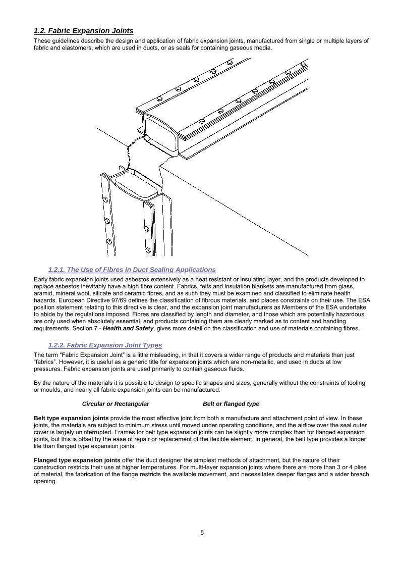
This guide describes in detail the applications and capabilities of fabric expansion joints, provides information on standard expansion joints and outlines the basic engineering concepts involved. The document provides information on materials used, plus other sections arranged to help in the design and specification of fabric expansion joints. Importantly, the guide provides the basis for maximising communication between user and manufacturer, in order that both may work together productively to solve challenges through the selection and use of the most appropriate technology for the application. 1.1 Overall definition The generic description ‘Expansion Joint’ covers a wide variety of products used to absorb movement in ducts and pipelines. There are many applications for these products, and there is some overlap between the various types of expansion joint that can be used for a specific purpose. However there are general groupings which help to define the types of expansion joint, and their applications. Both metallic and non-metallic expansion joints can be used in ducts or pipelines:
1.1.1. Metallic Expansion Joints or Bellows Thin metallic sheet is formed into multiple convolutions, which are welded to pipe ends or flanges for attachment. Most metallic expansion joints are circular, but for duct applications rectangular joints with mitred or circular corners are sometimes specified. The strength and robustness of the metal is an advantage in some applications, but this is countered by their relative stiffness, and the problems of metal fatigue. However the performance of metals can be defined more precisely than fabric or rubber, and comprehensive design codes allow the manufacture of metallic expansion joints for defined operating conditions and cycle life. The EJMA standard is accepted by most designers and users for safe operation of metallic expansion joints.
1.1.2. Rubber Pipeline Expansion Joints For pipeline applications where the operating pressure is low and temperature below 200°C, rubber expansion joints are commonly used. Manufactured from various elastomers, with fabric or wire reinforcing, they are fully vulcanised, and provide good movement capability with almost unlimited cycle life. As with any elastomeric product their life is limited by ageing, which is largely dependent on the operating conditons and environment. Rubber expansion joints are particularly useful for service with aggressive chemicals, and for abrasion resistance. Basic standards for rubber expansion joints are defined in the Fluid Sealing Association handbook on rubber expansion joints, but the very nature of rubber precludes much definition of performance.
1.1.3. Associated Products Almost any flexible material can be manufactured into an expansion joint, and there are a multitude of specific applications beyond the scope of these guidelines. Typical of these is the fluoroplastic range of machined or moulded bellows for resistance to chemicals.
Ducts Pipeline
Metallic
Non-Metallic
5
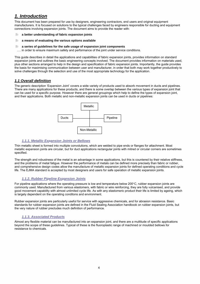
1.2. Fabric Expansion Joints These guidelines describe the design and application of fabric expansion joints, manufactured from single or multiple layers of fabric and elastomers, which are used in ducts, or as seals for containing gaseous media.
1.2.1. The Use of Fibres in Duct Sealing Applications Early fabric expansion joints used asbestos extensively as a heat resistant or insulating layer, and the products developed to replace asbestos inevitably have a high fibre content. Fabrics, felts and insulation blankets are manufactured from glass, aramid, mineral wool, silicate and ceramic fibres, and as such they must be examined and classified to eliminate health hazards. European Directive 97/69 defines the classification of fibrous materials, and places constraints on their use. The ESA position statement relating to this directive is clear, and the expansion joint manufacturers as Members of the ESA undertake to abide by the regulations imposed. Fibres are classified by length and diameter, and those which are potentially hazardous are only used when absolutely essential, and products containing them are clearly marked as to content and handling requirements. Section 7 - Health and Safety, gives more detail on the classification and use of materials containing fibres.
1.2.2. Fabric Expansion Joint Types The term “Fabric Expansion Joint” is a little misleading, in that it covers a wider range of products and materials than just “fabrics”. However, it is useful as a generic title for expansion joints which are non-metallic, and used in ducts at low pressures. Fabric expansion joints are used primarily to contain gaseous fluids. By the nature of the materials it is possible to design to specific shapes and sizes, generally without the constraints of tooling or moulds, and nearly all fabric expansion joints can be manufactured:
Circular or Rectangular Belt or flanged type Belt type expansion joints provide the most effective joint from both a manufacture and attachment point of view. In these joints, the materials are subject to minimum stress until moved under operating conditions, and the airflow over the seal outer cover is largely uninterrupted. Frames for belt type expansion joints can be slightly more complex than for flanged expansion joints, but this is offset by the ease of repair or replacement of the flexible element. In general, the belt type provides a longer life than flanged type expansion joints. Flanged type expansion joints offer the duct designer the simplest methods of attachment, but the nature of their construction restricts their use at higher temperatures. For multi-layer expansion joints where there are more than 3 or 4 plies of material, the fabrication of the flange restricts the available movement, and necessitates deeper flanges and a wider breach opening.
6
The common materials used in construction (for more information, please refer to Section 6. Materials): Elastomeric: Neoprene Reinforcing: Nylon EPDM Glass fabric Silicone Aramid Fluoroelastomer Wire Mesh For Multilayer joints: Supporting layer: Wire Mesh Wire Reinforced Fabric
Insulating layer: Glass fabric Glass felt
Mineral Wool Silicate fabric
Silicate felt Ceramic felt Chemical barrier: Fluoroplastics (for example, PTFE) Fluoroelastomer Metal foil Outer cover: Reinforced - Elastomer - Fluoroplastic
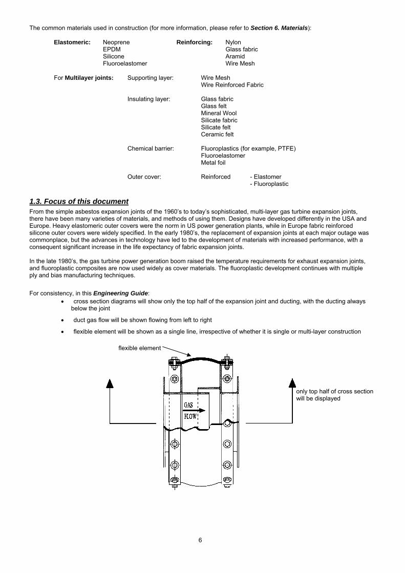
1.3. Focus of this document From the simple asbestos expansion joints of the 1960’s to today’s sophisticated, multi-layer gas turbine expansion joints, there have been many varieties of materials, and methods of using them. Designs have developed differently in the USA and Europe. Heavy elastomeric outer covers were the norm in US power generation plants, while in Europe fabric reinforced silicone outer covers were widely specified. In the early 1980’s, the replacement of expansion joints at each major outage was commonplace, but the advances in technology have led to the development of materials with increased performance, with a consequent significant increase in the life expectancy of fabric expansion joints. In the late 1980’s, the gas turbine power generation boom raised the temperature requirements for exhaust expansion joints, and fluoroplastic composites are now used widely as cover materials. The fluoroplastic development continues with multiple ply and bias manufacturing techniques. For consistency, in this Engineering Guide:
• cross section diagrams will show only the top half of the expansion joint and ducting, with the ducting always below the joint
• duct gas flow will be shown flowing from left to right
• flexible element will be shown as a single line, irrespective of whether it is single or multi-layer construction
only top half of cross section will be displayed
flexible element
7
1.4. Background to environmental legislation It is recognised that industry must reduce its impact on the environment if we are to continue global development for future generations (the so-called “sustainable development” option). A major contributory factor will be through the lowering of industrial emissions, which has been catalysed by a combination of public pressure, environmental legislation and the internal requirement to minimise the loss of valuable feedstocks. Large proportions of the emissions to atmosphere are represented by the by-products of combustion (notably the oxides of carbon, nitrogen and sulphur), along with known losses of volatile hydrocarbons and steam. In general, these are all emissions anticipated from the industrial process, under the control of the plant operator, and will not be considered further here. However, a proportion of industrial emissions occurs through unanticipated or spurious leaks in process systems. These equipment leaks are usually referred to as “fugitive emissions”, and in this area the sealing industry is playing a vital role, through the development and application of innovative sealing technology appropriate to low or zero emission requirements. Correct selection, installation and use of sealing materials are equally important to ensure reliable performance over the lifetime of the seal, and this is the prime focus in this publication. The development of legislation to control fugitive emissions has been well reported for both the USA1 and European markets2. Although the early developments started in the USA, the European Union is catching up quickly, and the focus of attention is moving closer together. Recent legislation in both the USA and Europe is aimed at the reduction of specific pollutants from specific operations. However, despite a broad series of approaches, there is no Europe-wide, harmonised legislation aimed at controlling fugitive emissions. Instead, Member States are implementing control measures within their own national legislative systems. Inevitably, these limits will tighten, and good seal performance will play an increasingly important role in ensuring efficient plant operation and emission control. By definition, high quality expansion joints play a major role in helping to minimise fugitive emissions.
1 USA Regulations on Fugitive Emissions (ESA Report No. 003/94), published by the European Sealing Association, 1994. 2 European Emission Legislation (ESA Publication No. 012/00), published by the European Sealing Association, 2000.
8
2. Definition of the products and technology Fabric expansion joints are flexible connectors designed to provide stress relief in ducting systems by absorbing movement caused by thermal changes. They also act as vibration isolators, shock absorbers and, in some instances, make up for minor misalignment of adjoining ducting or equipment. Fabric expansion joints may also be known as “compensators”. They are fabricated from a wide variety of materials, including synthetic elastomers, fabrics, insulation materials and fluoroplastics, dependent upon the design. The designs range from a single ply to complex, multi-ply constructions attached to metal frames for operation under extremes of temperature or corrosion.
2.1. Industry applications Since their introduction, expansion joints have been used to solve an increasing range of flexible sealing challenges. However, the major application is in power generation. As materials have been developed and the technology of expansion joint design have been improved, they have been used successfully in a much wider variety of industrial applications, including:
• Cement
• Chemical
• Heating and ventilation
• Marine and offshore
• Metal foundries
• Petrochemical
• Pollution control and flue-gas cleaning
• Power generation - co-generation - fossil fuel - gas turbine - nuclear
• Pulp and paper
• Steel and aluminium
• Waste incineration
2.2. Expansion joint technology Expansion joints provide flexibility in ductwork and are used to allow for 4 main situations:
- expansion or contraction of the duct due to temperature changes - isolation of components to minimise the effects of vibration or noise - movement of components during process operations - installation or removal of large components, and erection tolerances
The benefits of fabric expansion joints include: Large movements in a short length – this requires fewer expansion joints, reducing the overall number of units and providing additional economies Ability to absorb simultaneous movements easily in more than one plane – this allows the duct designer to accommodate composite movements in fewer (and simpler) expansion joints Very low forces required to move the expansion joint – the low spring rate enables their use to isolate stresses on large, relatively lightweight, equipment. A particular example is a gas turbine exhaust, where it is crucial to minimise the forces from the duct expansion on the turbine frame Corrosion resistant materials of construction – modern technology materials enable the use in aggressive chemical conditions Noise and vibration resistance – fabric expansion joints provide a high degree of noise isolation and vibration damping Ease of installation and maintenance Minimal replacement cost – the fabric of the expansion joint assembly can be replaced simply and economically Design freedom – fabric expansion joints can be tailored to suit the duct application, with taper, transition or irregular shape, so allowing the designer the maximum variety of options Thermal breaks – self-insulating properties of the fabric allow simple hot-to-cold transition
9
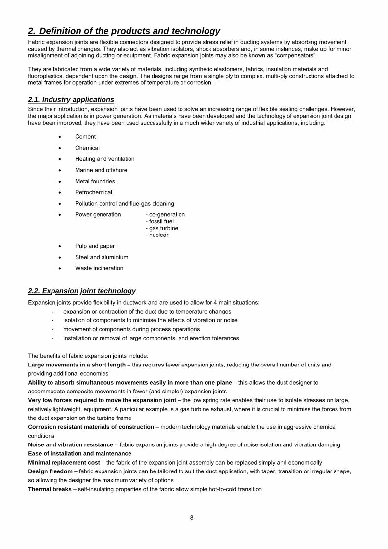
3. Expansion joint construction and configuration 3.1 Construction There are 2 basic forms of construction, dependent upon the number of layers in the expansion joint:
• Single layer construction
• Multi-layer construction
3.1.1. Single layer construction An expansion joint formed of one consolidated layer, often constructed from elastomers and reinforcement materials or fluoroplastics and reinforcement materials:
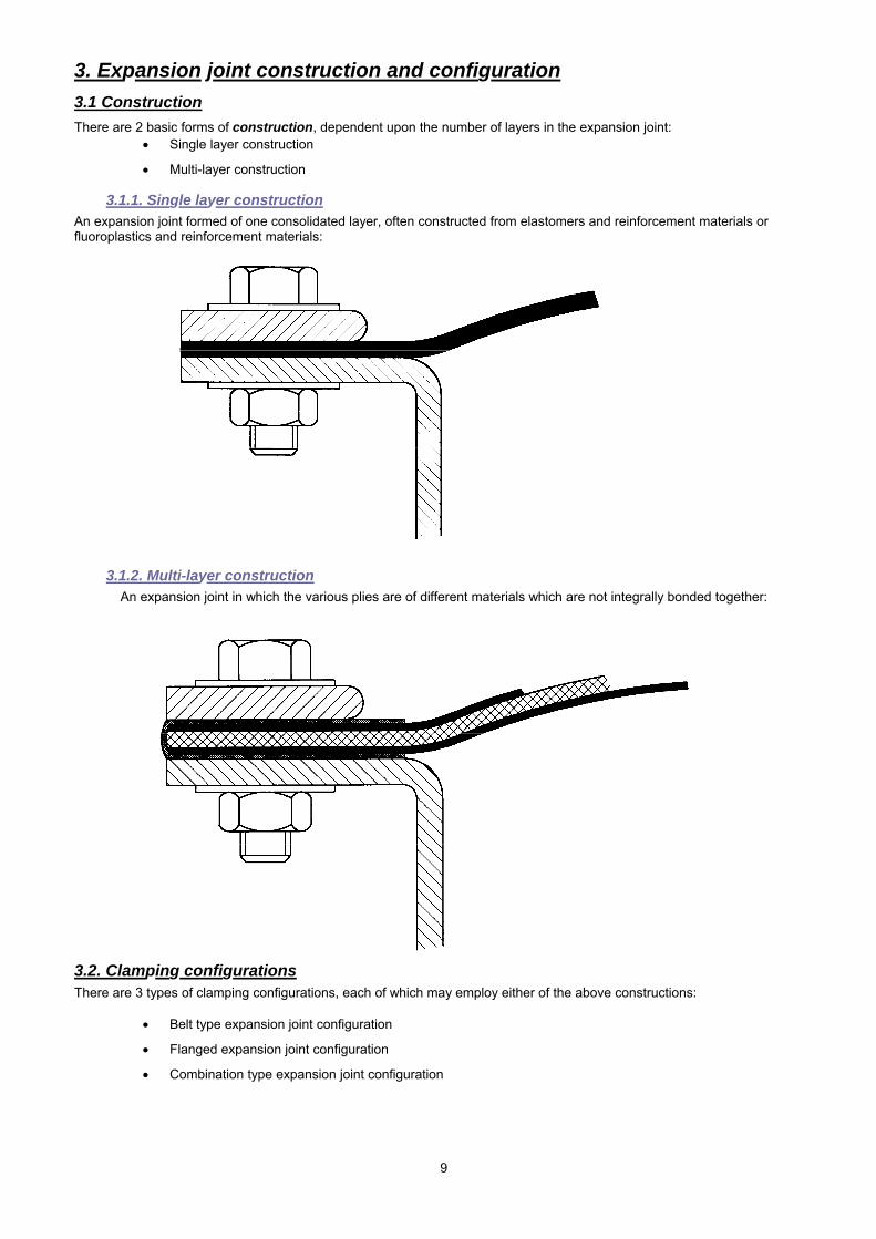
3.1.2. Multi-layer construction An expansion joint in which the various plies are of different materials which are not integrally bonded together:
3.2. Clamping configurations There are 3 types of clamping configurations, each of which may employ either of the above constructions:
• Belt type expansion joint configuration
• Flanged expansion joint configuration
• Combination type expansion joint configuration
10
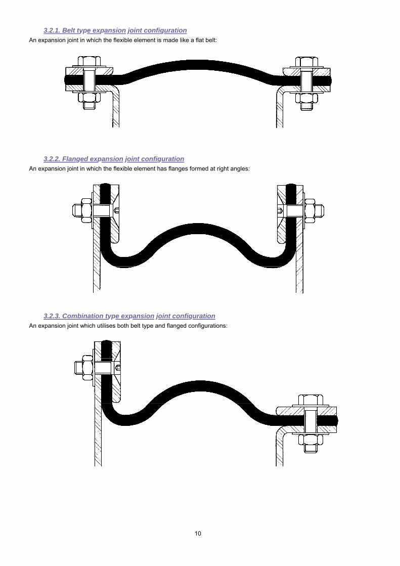
3.2.1. Belt type expansion joint configuration An expansion joint in which the flexible element is made like a flat belt:
3.2.2. Flanged expansion joint configuration An expansion joint in which the flexible element has flanges formed at right angles:
3.2.3. Combination type expansion joint configuration An expansion joint which utilises both belt type and flanged configurations:
11
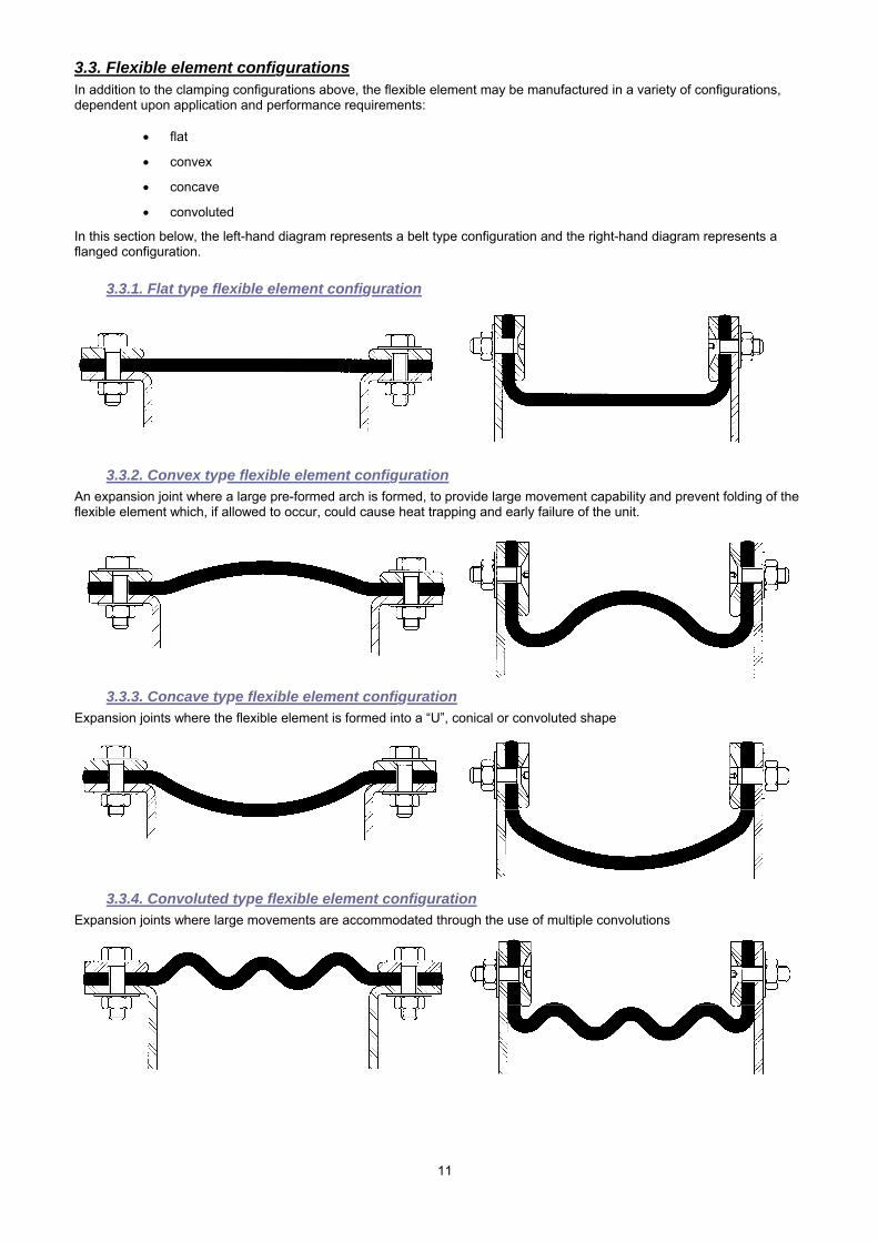
3.3. Flexible element configurations In addition to the clamping configurations above, the flexible element may be manufactured in a variety of configurations, dependent upon application and performance requirements:
• flat
• convex
• concave
• convoluted
In this section below, the left-hand diagram represents a belt type configuration and the right-hand diagram represents a flanged configuration.
3.3.1. Flat type flexible element configuration
3.3.2. Convex type flexible element configuration An expansion joint where a large pre-formed arch is formed, to provide large movement capability and prevent folding of the flexible element which, if allowed to occur, could cause heat trapping and early failure of the unit.
3.3.3. Concave type flexible element configuration Expansion joints where the flexible element is formed into a “U”, conical or convoluted shape
3.3.4. Convoluted type flexible element configuration Expansion joints where large movements are accommodated through the use of multiple convolutions
12
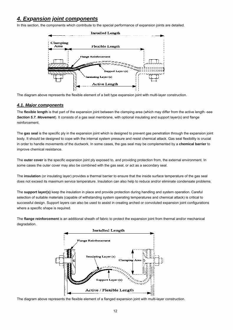
4. Expansion joint components In this section, the components which contribute to the special performance of expansion joints are detailed.
The diagram above represents the flexible element of a belt type expansion joint with multi-layer construction.
4.1. Major components The flexible length is that part of the expansion joint between the clamping area (which may differ from the active length -see Section 5.7. Movement). It consists of a gas seal membrane, with optional insulating and support layer(s) and flange reinforcement. The gas seal is the specific ply in the expansion joint which is designed to prevent gas penetration through the expansion joint body. It should be designed to cope with the internal system pressure and resist chemical attack. Gas seal flexibility is crucial in order to handle movements of the ductwork. In some cases, the gas seal may be complemented by a chemical barrier to improve chemical resistance. The outer cover is the specific expansion joint ply exposed to, and providing protection from, the external environment. In some cases the outer cover may also be combined with the gas seal, or act as a secondary seal. The insulation (or insulating layer) provides a thermal barrier to ensure that the inside surface temperature of the gas seal does not exceed its maximum service temperature. Insulation can also help to reduce and/or eliminate condensate problems. The support layer(s) keep the insulation in place and provide protection during handling and system operation. Careful selection of suitable materials (capable of withstanding system operating temperatures and chemical attack) is critical to successful design. Support layers can also be used to assist in creating arched or convoluted expansion joint configurations where a specific shape is required. The flange reinforcement is an additional sheath of fabric to protect the expansion joint from thermal and/or mechanical degradation.
The diagram above represents the flexible element of a flanged expansion joint with multi-layer construction.
13
4.2. Other key components Components described in this section include:
• bolsters
• clamping methods
• corners
• dust seals
• frames
• internal flow sleeves
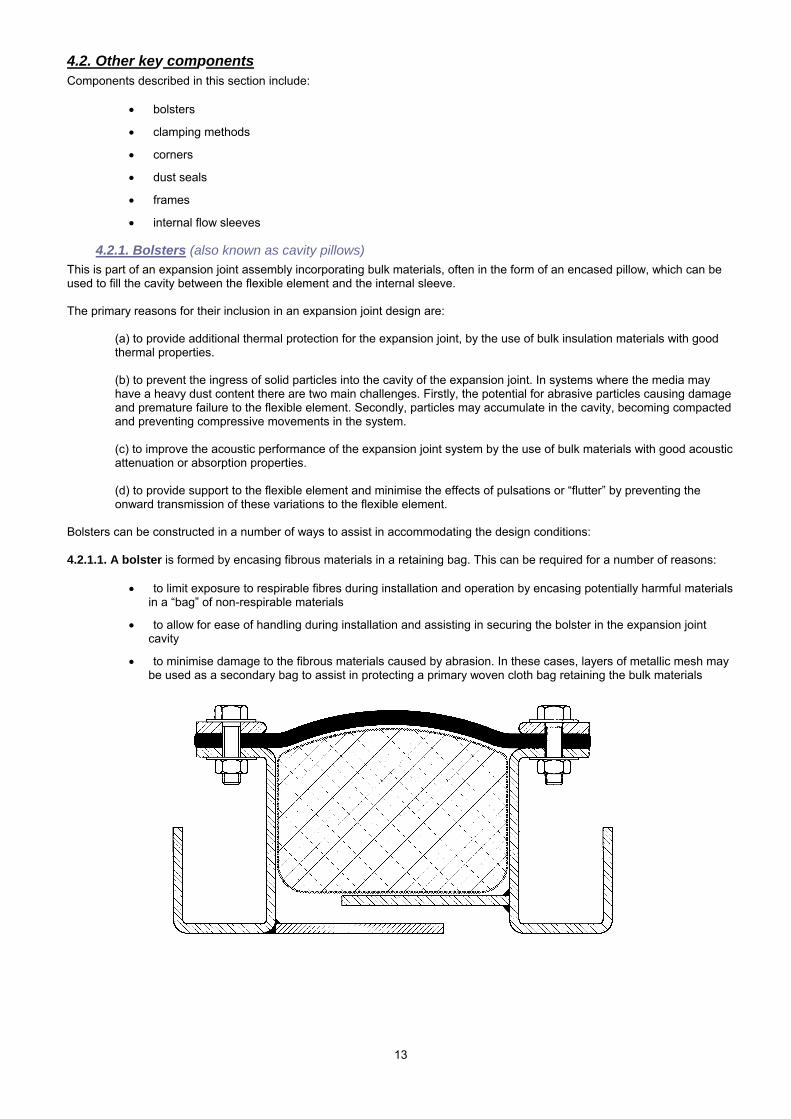
4.2.1. Bolsters (also known as cavity pillows) This is part of an expansion joint assembly incorporating bulk materials, often in the form of an encased pillow, which can be used to fill the cavity between the flexible element and the internal sleeve. The primary reasons for their inclusion in an expansion joint design are:
(a) to provide additional thermal protection for the expansion joint, by the use of bulk insulation materials with good thermal properties.
(b) to prevent the ingress of solid particles into the cavity of the expansion joint. In systems where the media may have a heavy dust content there are two main challenges. Firstly, the potential for abrasive particles causing damage and premature failure to the flexible element. Secondly, particles may accumulate in the cavity, becoming compacted and preventing compressive movements in the system.
(c) to improve the acoustic performance of the expansion joint system by the use of bulk materials with good acoustic attenuation or absorption properties.
(d) to provide support to the flexible element and minimise the effects of pulsations or “flutter” by preventing the onward transmission of these variations to the flexible element.
Bolsters can be constructed in a number of ways to assist in accommodating the design conditions: 4.2.1.1. A bolster is formed by encasing fibrous materials in a retaining bag. This can be required for a number of reasons:
• to limit exposure to respirable fibres during installation and operation by encasing potentially harmful materials in a “bag” of non-respirable materials
• to allow for ease of handling during installation and assisting in securing the bolster in the expansion joint cavity
• to minimise damage to the fibrous materials caused by abrasion. In these cases, layers of metallic mesh may be used as a secondary bag to assist in protecting a primary woven cloth bag retaining the bulk materials
14
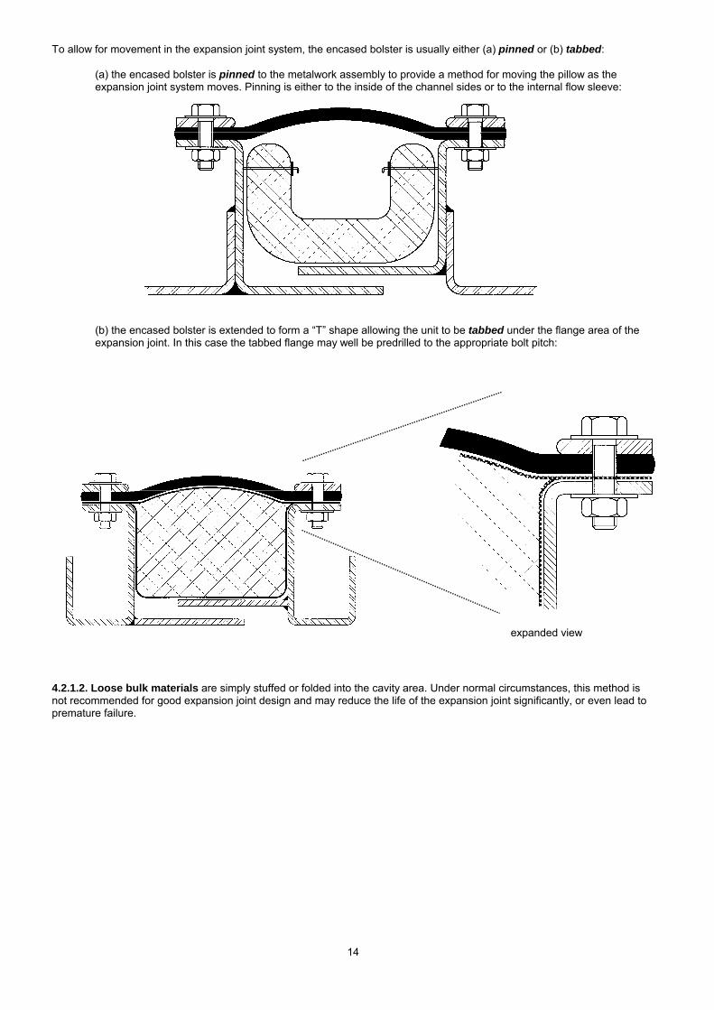
To allow for movement in the expansion joint system, the encased bolster is usually either (a) pinned or (b) tabbed:
(a) the encased bolster is pinned to the metalwork assembly to provide a method for moving the pillow as the expansion joint system moves. Pinning is either to the inside of the channel sides or to the internal flow sleeve:
(b) the encased bolster is extended to form a “T” shape allowing the unit to be tabbed under the flange area of the expansion joint. In this case the tabbed flange may well be predrilled to the appropriate bolt pitch:
4.2.1.2. Loose bulk materials are simply stuffed or folded into the cavity area. Under normal circumstances, this method is not recommended for good expansion joint design and may reduce the life of the expansion joint significantly, or even lead to premature failure.
expanded view
15
4.2.2. Clamping devices There are several methods of clamping fabric expansion joints, some of the most common are detailed below: Expansion joint type
Clamping device
Duct cross section
Duct size Operating pressure
Cost of clamping method
Comments
Belt Worm drive Circular Small Low Low Fast installation T-bolt Circular Small-large Low Low Fast installation. Use toggle in several
segments for larger diameters, to ensure even clamping pressure
Clamp bar Circular/ rectangular
Small-large Low-high Medium High temperature capability
External clamp
Circular/ rectangular
Small-large Low High
Flanged Clamp bar Circular/ rectangular
Small-large Low-high Medium Moderate temperature capability
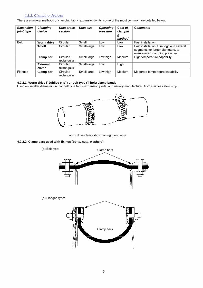
4.2.2.1. Worm drive ("Jubilee clip") or bolt type (T-bolt) clamp bands Used on smaller diameter circular belt type fabric expansion joints, and usually manufactured from stainless steel strip.
4.2.2.2. Clamp bars used with fixings (bolts, nuts, washers)
(a) Belt type:
(b) Flanged type:
Clamp bars
Clamp bars
worm drive clamp shown on right end only
16
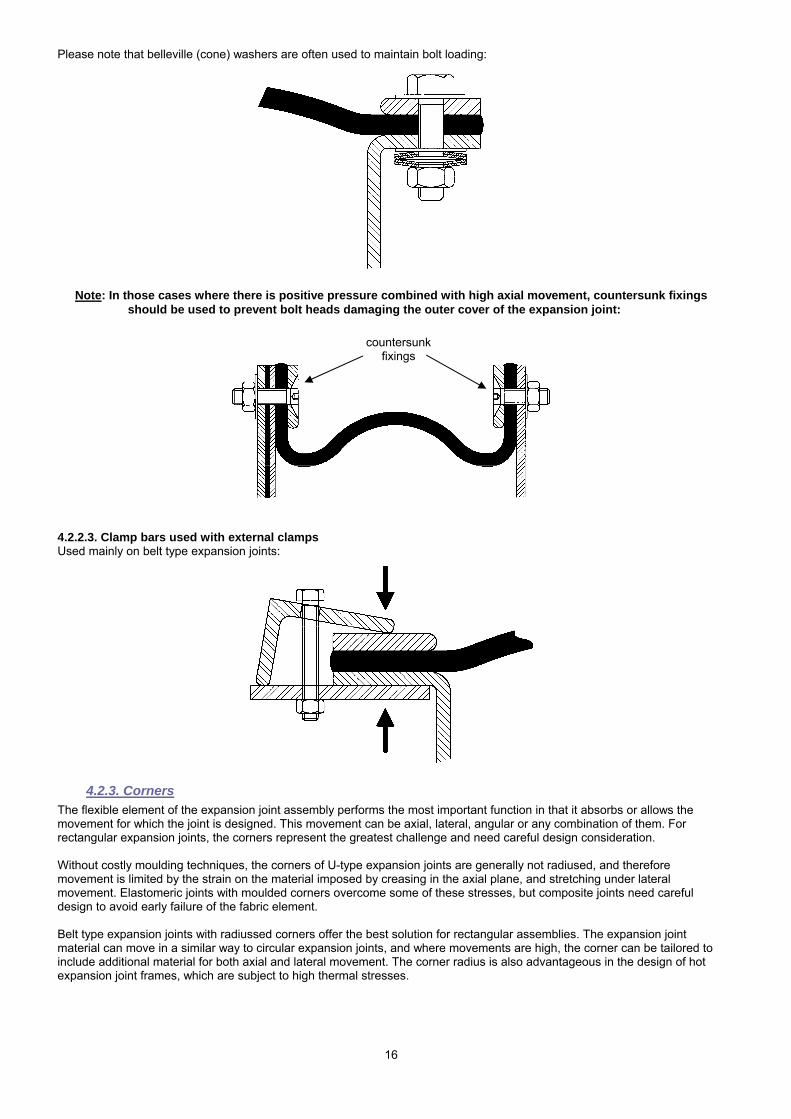
Please note that belleville (cone) washers are often used to maintain bolt loading:
Note: In those cases where there is positive pressure combined with high axial movement, countersunk fixings
should be used to prevent bolt heads damaging the outer cover of the expansion joint:
4.2.2.3. Clamp bars used with external clamps Used mainly on belt type expansion joints:
4.2.3. Corners The flexible element of the expansion joint assembly performs the most important function in that it absorbs or allows the movement for which the joint is designed. This movement can be axial, lateral, angular or any combination of them. For rectangular expansion joints, the corners represent the greatest challenge and need careful design consideration. Without costly moulding techniques, the corners of U-type expansion joints are generally not radiused, and therefore movement is limited by the strain on the material imposed by creasing in the axial plane, and stretching under lateral movement. Elastomeric joints with moulded corners overcome some of these stresses, but composite joints need careful design to avoid early failure of the fabric element. Belt type expansion joints with radiussed corners offer the best solution for rectangular assemblies. The expansion joint material can move in a similar way to circular expansion joints, and where movements are high, the corner can be tailored to include additional material for both axial and lateral movement. The corner radius is also advantageous in the design of hot expansion joint frames, which are subject to high thermal stresses.
countersunk fixings
17
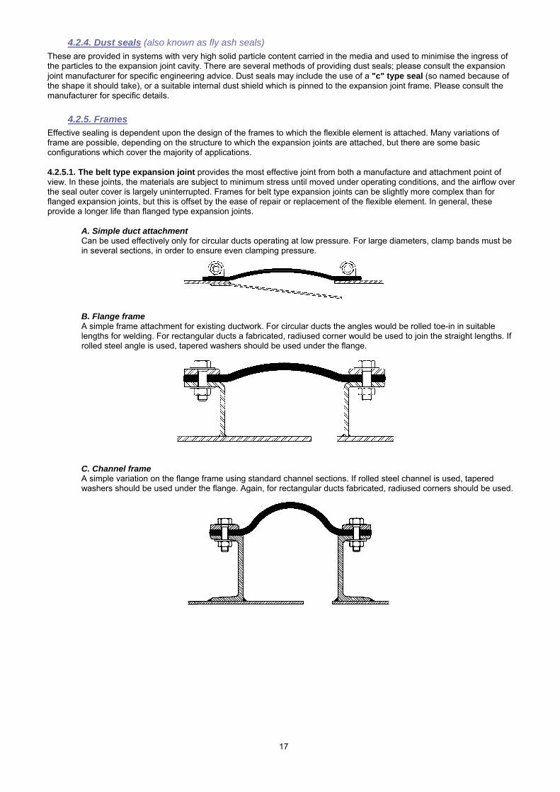
4.2.4. Dust seals (also known as fly ash seals) These are provided in systems with very high solid particle content carried in the media and used to minimise the ingress of the particles to the expansion joint cavity. There are several methods of providing dust seals; please consult the expansion joint manufacturer for specific engineering advice. Dust seals may include the use of a "c" type seal (so named because of the shape it should take), or a suitable internal dust shield which is pinned to the expansion joint frame. Please consult the manufacturer for specific details.
4.2.5. Frames Effective sealing is dependent upon the design of the frames to which the flexible element is attached. Many variations of frame are possible, depending on the structure to which the expansion joints are attached, but there are some basic configurations which cover the majority of applications. 4.2.5.1. The belt type expansion joint provides the most effective joint from both a manufacture and attachment point of view. In these joints, the materials are subject to minimum stress until moved under operating conditions, and the airflow over the seal outer cover is largely uninterrupted. Frames for belt type expansion joints can be slightly more complex than for flanged expansion joints, but this is offset by the ease of repair or replacement of the flexible element. In general, these provide a longer life than flanged type expansion joints.
A. Simple duct attachment Can be used effectively only for circular ducts operating at low pressure. For large diameters, clamp bands must be in several sections, in order to ensure even clamping pressure.
B. Flange frame A simple frame attachment for existing ductwork. For circular ducts the angles would be rolled toe-in in suitable lengths for welding. For rectangular ducts a fabricated, radiused corner would be used to join the straight lengths. If rolled steel angle is used, tapered washers should be used under the flange.
C. Channel frame A simple variation on the flange frame using standard channel sections. If rolled steel channel is used, tapered washers should be used under the flange. Again, for rectangular ducts fabricated, radiused corners should be used.
18
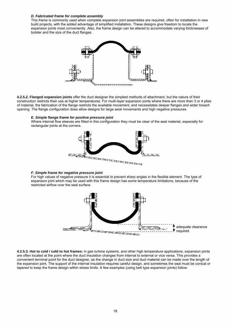
D. Fabricated frame for complete assembly This frame is commonly used when complete expansion joint assemblies are required, often for installation in new build projects, with the added advantage of simplified installation. These designs give freedom to locate the expansion joints most conveniently. Also, the frame design can be altered to accommodate varying thicknesses of bolster and the size of the duct flanges.
4.2.5.2. Flanged expansion joints offer the duct designer the simplest methods of attachment, but the nature of their construction restricts their use at higher temperatures. For multi-layer expansion joints where there are more than 3 or 4 plies of material, the fabrication of the flange restricts the available movement, and necessitates deeper flanges and wider breach opening. The flange configuration does allow designs for large axial movements and high negative pressures.
E. Simple flange frame for positive pressure joint Where internal flow sleeves are fitted in this configuration they must be clear of the seal material, especially for rectangular joints at the corners.
F. Simple frame for negative pressure joint For high values of negative pressure it is essential to prevent sharp angles in the flexible element. The type of expansion joint which may be used with this frame design has some temperature limitations, because of the restricted airflow over the seal surface.
4.2.5.3. Hot to cold / cold to hot frames: in gas turbine systems, and other high temperature applications, expansion joints are often located at the point where the duct insulation changes from internal to external or vice versa. This provides a convenient terminal point for the duct designer, as the change in duct size and duct material can be made over the length of the expansion joint. The support of the internal insulation requires careful design, and sometimes the seal must be conical or tapered to keep the frame design within stress limits. A few examples (using belt type expansion joints) follow:
adequate clearance required
19
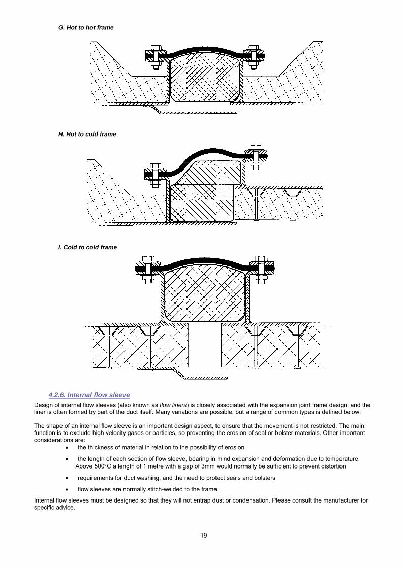
G. Hot to hot frame
H. Hot to cold frame
I. Cold to cold frame
4.2.6. Internal flow sleeve Design of internal flow sleeves (also known as flow liners) is closely associated with the expansion joint frame design, and the liner is often formed by part of the duct itself. Many variations are possible, but a range of common types is defined below. The shape of an internal flow sleeve is an important design aspect, to ensure that the movement is not restricted. The main function is to exclude high velocity gases or particles, so preventing the erosion of seal or bolster materials. Other important considerations are:
• the thickness of material in relation to the possibility of erosion
• the length of each section of flow sleeve, bearing in mind expansion and deformation due to temperature. Above 500°C a length of 1 metre with a gap of 3mm would normally be sufficient to prevent distortion
• requirements for duct washing, and the need to protect seals and bolsters
• flow sleeves are normally stitch-welded to the frame
Internal flow sleeves must be designed so that they will not entrap dust or condensation. Please consult the manufacturer for specific advice.
20
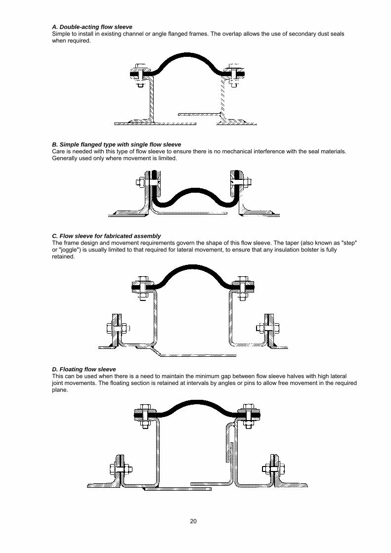
A. Double-acting flow sleeve Simple to install in existing channel or angle flanged frames. The overlap allows the use of secondary dust seals when required.
B. Simple flanged type with single flow sleeve Care is needed with this type of flow sleeve to ensure there is no mechanical interference with the seal materials. Generally used only where movement is limited.
C. Flow sleeve for fabricated assembly The frame design and movement requirements govern the shape of this flow sleeve. The taper (also known as "step" or "joggle") is usually limited to that required for lateral movement, to ensure that any insulation bolster is fully retained.
D. Floating flow sleeve This can be used when there is a need to maintain the minimum gap between flow sleeve halves with high lateral joint movements. The floating section is retained at intervals by angles or pins to allow free movement in the required plane.
21
5. Design and selection criteria This section aims to highlight the important criteria which will affect the selection of the joint and its engineering design requirements. Included here are:
• Ambient conditions • Bolting guidelines for bolted expansion joints • Dust loading and velocity • Finite element analysis • Leakage • Moisture content, condensation and washing • Movement • Noise • Pressure - pulsation and flutter • Temperature • Tolerances
Expansion joints must be designed to absorb specified movements (see Section 5.7. Movement), with suitable methods of attachment. The operating conditions such as temperature, pressure and chemical loading must be considered. The design of the expansion joint should be verified by a drawing or scheme, which may be supported by finite element analysis.
5.1. Ambient conditions The ambient conditions local to fabric expansion joints play an important part in their design and selection.
5.1.1. Ambient temperature An expansion joint should not be located in an area of poor air circulation, or subject to high temperature radiation. Fabric expansion joints working at elevated temperatures (above 250°C) depend upon a temperature gradient across the joint. This gradient is the difference between the high internal temperature (hot face) and colder external temperature (cold face) of the joint. High ambient temperatures in the vicinity of the joint will reduce this temperature gradient reducing the rate at which heat can be radiated from the external surface of the joint. This in turn will lead to failure of the primary seal (i.e. PTFE membrane) and hence the joint. Therefore, it is important to ensure that adequate provision is made to keep local ambient temperatures within manufacturer’s recommendations, and external lagging or insulating of joints is generally not allowed. Where cold external ambient conditions prevail, due consideration should be given to the possibility of condensation forming inside fabric expansion joints. Counter measures such as internal or external insulation may be considered appropriate.
5.1.2. Environment Fabric expansion joints are very often situated in arduous industrial locations such as power generation plants, chemical works, cement plants etc. In such locations, they may be subjected to higher than normal levels of pollutants, some of which may contain aggressive agents, with possible attack to the elastomer outer cover of the joint. If the type and concentration of such pollutants is known at the design stage, it is possible to design a joint which will resist such attack by selection of an appropriate outer cover, resistant to specific agents.
5.1.3. Location Whether a joint is located internally within a building or outside and exposed to the elements may also have a bearing on the selection of the type of outer cover. Internally located joints may not necessarily require waterproof outer covers.
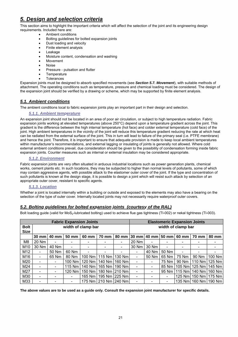
5.2. Bolting guidelines for bolted expansion joints (courtesy of the RAL) Bolt loading guide (valid for MoS2-lubricated bolting) used to achieve flue gas tightness (TI-002) or nekal tightness (TI-003).
Fabric Expansion Joints Elastomeric Expansion JointsBolt Size
width of clamp bar width of clamp bar
30 mm 40 mm 50 mm 60 mm 70 mm 80 mm 30 mm 40 mm 50 mm 60 mm 70 mm 80 mmM8 20 Nm - - - - - 20 Nm - - - - -
M10 30 Nm 40 Nm - - - - 30 Nm 30 Nm - - - -M12 - 50 Nm 60 Nm - - - - 40 Nm 50 Nm - - -M16 - 65 Nm 80 Nm 100 Nm 115 Nm 130 Nm - 50 Nm 65 Nm 75 Nm 90 Nm 100 NmM20 - - 100 Nm 120 Nm 140 Nm 160 Nm - - 75 Nm 90 Nm 110 Nm 125 NmM24 - - 115 Nm 140 Nm 165 Nm 190 Nm - - 85 Nm 105 Nm 125 Nm 145 NmM27 - - 120 Nm 150 Nm 180 Nm 210 Nm - - 95 Nm 115 Nm 140 Nm 160 NmM30 - - - 165 Nm 195 Nm 225 Nm - - - 125 Nm 150 Nm 175 NmM33 - - - 175 Nm 210 Nm 240 Nm - - - 135 Nm 160 Nm 190 Nm
The above values are to be used as a guide only. Consult the expansion joint manufacturer for specific details.
22
5.2.1. Guidelines for the dimensioning of clamp bars Width 30 40 50 60 70 80 90 100 mm Thickness 6/8 8/10 8/10 10/12 10/12 12 12 12/15 mm Bolt spacing 60 80 100 100 120 120 120 120 mm Bolts M 8/10 10/12 10/12 12/16 12/16 16 16 16/20
5.2.2. Reduction of the mechanical strength of the bolting at higher temperatures
Class of strength
Temperature
+20°C +100°C +200°C +250°C +300°C modulus of elasticity ReL (N/mm²)
4.6 240 210 190 170 140 5.6 300 270 230 215 195 8.8 640 590 540 510 408
10.9 940 875 790 745 705 12.9 1100 1020 925 875 825
5.3. Dust loading and velocity The content of dust in the medium may require a specific design of the expansion joint section and the inner sleeves. In general, the following must be avoided:
- abrasion caused by dust particles - sedimentation and compression of dust in the flexible element
Due to the large variety of applications and associated complexities, please refer to the expansion joint manufacturer for specific engineering advice. See also Section 4.2.4. Dust seals
5.4. Finite element analysis Finite Element Analysis is a computerised method for predicting how a real world structure or assembly will react to forces, heat, vibration, mechanical stress etc. in terms of whether it will break, wear out, or work as it was intended. It is called ‘analysis’ but in the product design cycle it is the method used to predict what will happen when the product is used. The finite element method works by breaking a real object into a large number of elements, and the behaviour of each element is examined in the conditions in which it will operate, by a set of mathematical equations. The computer programme then adds up all the individual behaviours to predict the behaviour of the complete object. The Finite Element Method is used to predict the behaviour of expansion joints with respect to the physical phenomena of:
- heat transfer - mechanical stress
- vibration The method is used widely to verify the design of expansion joints and their structures used in gas turbine exhaust systems.
5.5. Leakage Fabric expansion joints are designed to be as leak tight as is reasonably practical. Although under laboratory conditions it is a relatively simple matter to demonstrate zero leakage, or nekal tightness, high temperature multiple layer expansion joints should not be considered leak tight (or zero leakage) in service without first verifying site performance with extensive testing under operating conditions. Through the careful selection and design of single layer elastomeric expansion joints, with their inherent resilience, it is much easier to ensure zero leakage systems, provided adequate attention is paid to the quality and design of adjacent metalwork. The vast majority of expansion joints (both single and multiple layer) can be considered leak tight through the body of the expansion joint, provided suitable materials have been specified. However, special attention should be drawn to the general metalwork condition and design, clamping areas and their surface finishes, fixing systems such as bolts or clamps and the flange reinforcements of expansion joints. It is these areas where there is the greatest potential for system losses. Where practical, new metalwork supplied with the expansion joint integrally installed (an expansion joint “cartridge” system) and supplied direct from the manufacturers’ facilities will almost always ensure a much lower rate of leakage than field splices and installation of the expansion joint to metalwork at site.
23
Under laboratory conditions it is possible to demonstrate flue-gas tight 3 and nekal tight 4 systems, using appropriate test methods5. To ensure nekal tightness in service, these types of test must be carried out after installation on site.
5.6. Moisture content, condensation and washing Moisture within a flue duct system can have a severe, detrimental effect on the life of fabric expansion joints and therefore, should be considered carefully. At operating temperatures above the dew point of the fluid, the moisture content will appear only when the system cools down. However, this moisture often appears as aggressive condensate and is an important factor if there are frequent thermal cycles. At operating temperatures below the dew point, the media may contain a high degree of moisture, which can be very corrosive and damaging to the expansion joint. Where cold ambient conditions prevail, due consideration should be given to the use of fabric expansion joints as they may give rise to condensation problems. Condensation can occur when a joint is located in a relatively low temperature duct system. The joint will provide an internal cold face on which condensation can form if the cold face falls below dew point, giving rise to the formation of condensate which will attack the joint from the inside causing premature failure. This can be countered by providing external insulation (note; internal insulation should be avoided). Joints should be externally insulated only on applications where the internal duct temperature is below the maximum temperature capabilities of the constituent joint materials. Further consideration may be given to the use of alternative materials which are less effected by acidic condensate. As mentioned under Section 4.2.6., internal flow sleeves must be designed so that they will not entrap dust or condensate. Please consult the manufacturer for specific advice. Where duct or gas turbine washing is required, provision should be made for a suitable drain adjacent to the expansion joint, in order to prevent the accumulation of moisture in the expansion joint material. Where possible, the expansion joint should not be the lowest point of the system.
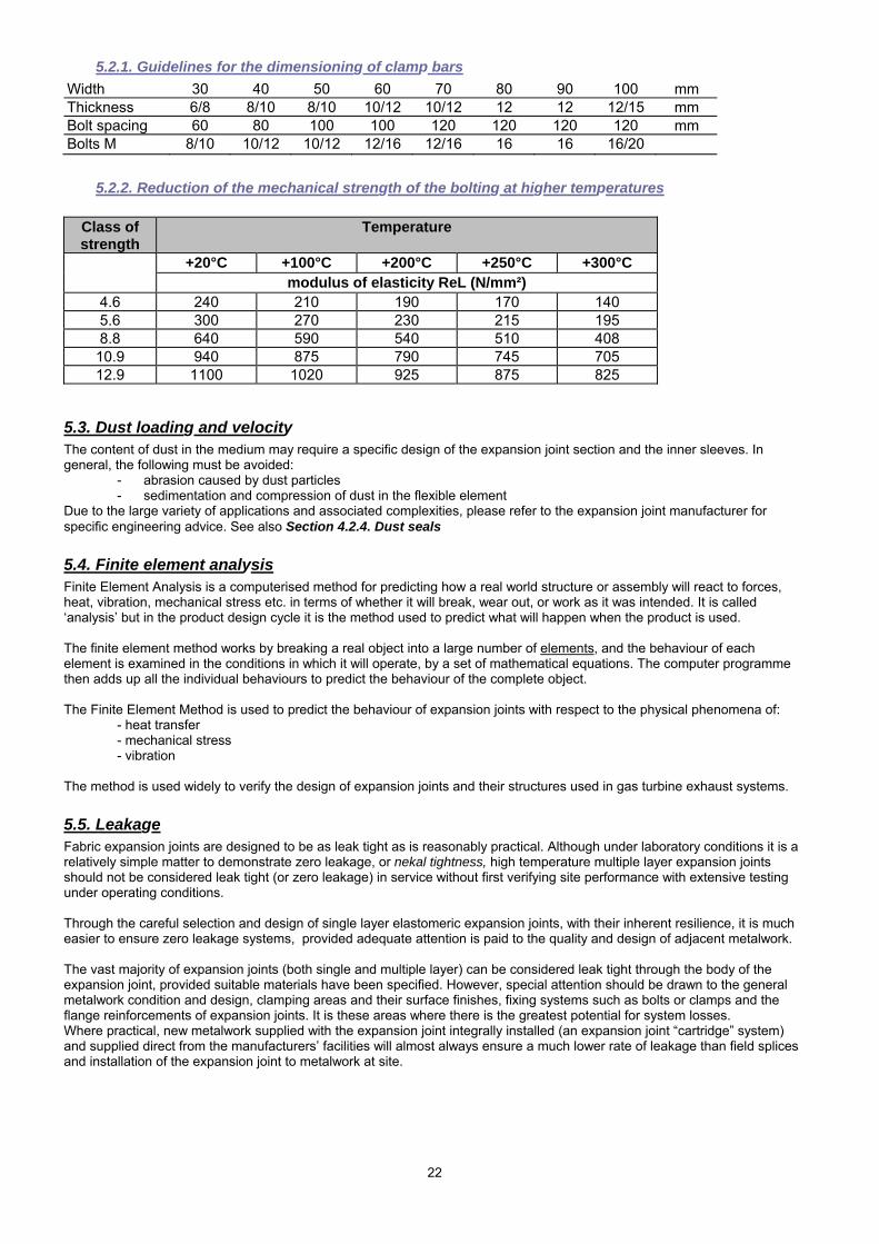
5.7. Movement Fabric expansion joints are designed to absorb movements and misalignments in ducts and pipelines. The active length of the expansion joint is that part which allows movement. It absorbs vibration and thermal movements of the ductwork, and may or may not be the same as the flexible length, which is that part of the expansion joint between the clamping areas:
Movements are normally induced by thermal expansion of the duct plate or pipe, but other types of movements are also possible, such as wind, snow load, duct misalignment, vibration, settling and earthquake.
3 Test specification RAL TI-002 Rev. 1 – 06/98 Flue-Gas Tight Fabric Expansion Joints refers to leak tight as “…no bubbles may appear in the bellows area…” and that “…the occurrence of a limited number of foam bubbles in the clamping area and joint area of the bellows is however permitted…”. 4 Test specification RAL TI-003 Rev. 1 – 06/98 Nekal Tight Fabric Expansion Joints refers to nekal tight as “…no bubbles may appear in the bellows area…” and that “…this refers to both the bellows area and to the clamping area…”. 5 Test methods similar to DECHEMA Information Bulletin ZfP 1, annex 2 Item 2.2 “Bubble method with foaming liquid”.
24
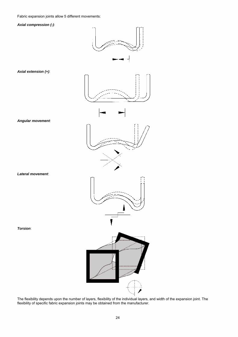
Fabric expansion joints allow 5 different movements: Axial compression (-):
Axial extension (+):
Angular movement:
Lateral movement:
Torsion:
The flexibility depends upon the number of layers, flexibility of the individual layers, and width of the expansion joint. The flexibility of specific fabric expansion joints may be obtained from the manufacturer.
25
5.7.1. Vibration and movement cycles Movement caused by vibration should not be confused with movement due to thermal cycling, which is slow and relatively infrequent. Fibrous materials are poor in conditions of high frequency and amplitude. Consequently, vibrations must be considered separately from thermal movements, in order to ensure correct material selection and provide suitable design recommendations. Please consult the manufacturer.
5.8. Noise In-duct noise breakout may be an important design consideration under certain circumstances, and can be reduced by acoustic treatment of the duct. Fabric expansion joints may be the primary source of noise breakout in a duct system, and an internal acoustic bolster may be incorporated into the design to reduce such noise. The bolster would normally be manufactured from insulation material encased in a temperature resistant woven fabric or wire mesh (or both) and located between the joint and the internal flow sleeve. External acoustic treatment of fabric expansion joints is not usually permissible for reasons stated in Section 5.1.1. Ambient temperature. The design of the internal flow sleeve(s) can also play an important part in the acoustic performance of a joint.
5.9. Pressure - pulsation and flutter The operating pressure in a system is a crucial factor affecting the design of fabric expansion joints. The very flexible nature of the materials brings a number of design issues which must be addressed. Although maximum operating pressures in duct systems are low by comparison with pipeline systems, wide variations of pressure, such as a change from positive to negative, or short term peak pressures can occur. Such variations should be reflected in the design pressure specified, and the measure of gas tightness expected by the customer. Particular care in the choice and construction of materials must allow for:
containment of the stated design pressure under all conditions of movement and temperature, without over-stressing any of the expansion joint element
changes from positive to negative pressure which could entrap materials under compression, or cause them to be in contact with sharp or hot parts of a duct
high positive pressure and compression allowing materials to abrade on bolt heads of clamp flanges changes in pressure causing significant air spaces between layers of composite joint materials, which could allow
circulation of hot gas pressure surges occurring as a result of system operation
5.9.1. Pulsation Pressure pulsation in a duct or pipeline can be detrimental to a fabric expansion joint, particularly those manufactured from plies of woven glass-cloth or ceramics. Rapid variation in pressure causes fatigue of the fibres, and can lead to premature failure of the expansion joint. Particular caution is required when designing expansion joints for combustion engine exhaust systems to ensure that the joint is not fitted too close to the engine. A sufficient distance is required to allow the pressure fluctuations to subside.
5.9.2. Flutter Flutter can be induced by fans, particularly where the system is unbalanced, and the materials used for expansion joints adjoining fans must be selected with this in mind. To overcome flutter of the joint materials, which could lead to premature failure, the materials must be of sufficient thickness and density to damp out the oscillations. Reinforced elastomeric materials are commonly specified for expansion joints fitted to the fan inlet or outlet. Flutter in expansion joint seals can be induced by high gas velocity, but is usually eliminated by careful design of a suitable flow liner attached to the duct or joint frame. The inclusion of a bolster can help to minimise flutter.
5.10. Temperature For information on ambient temperature, please refer to 5.1.1. Ambient temperature.
5.10.1. Operating temperature The operating temperature is the normal temperature of the media within the flue duct system under operation. Normally indicated in degrees C as design or maximum operating temperature. See also Section 5.6. Moisture content, condensation and washing.
5.10.2. Thermal cycles The definition of a thermal cycle is when the temperature in a flue duct system moves from ambient to full operating temperature and then returns to ambient. The number of thermal cycles is often used when calculating the life expectancy of steel frames for gas turbine exhaust systems or when considering the number of times moisture could appear in the system on cool down. See also Section 5.6. Moisture content, condensation and washing.
26
5.10.3. Excursion temperature Occasionally, flue duct systems will have an upset condition or excursion. This is a situation when, for a short period of time, the temperature in the system increases above normal operating temperature. The expansion joint designer must consider this upset condition for duration and temperature when making material selection.
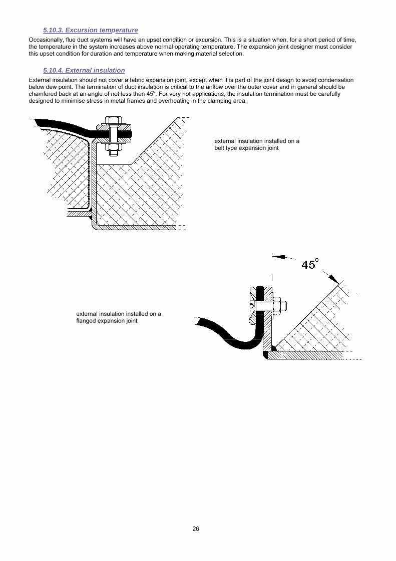
5.10.4. External insulation External insulation should not cover a fabric expansion joint, except when it is part of the joint design to avoid condensation below dew point. The termination of duct insulation is critical to the airflow over the outer cover and in general should be chamfered back at an angle of not less than 45o. For very hot applications, the insulation termination must be carefully designed to minimise stress in metal frames and overheating in the clamping area.
external insulation installed on a flanged expansion joint
external insulation installed on a belt type expansion joint
27
5.11. Tolerances The flexible nature of fabric expansion joints reduces the need for very tight manufacturing tolerances for the flexible element. However, it is necessary to define the interface tolerances for expansion joints and their frames for their connection to ducts or other components. Please consult the following standards for general tolerances:
- ISO 2768-1 (1989) Tolerances for linear and angular dimensions without individual tolerance indications - EN ISO 13920 (1996) General tolerances for welded constructions - dimensions for lengths and angles
Other national and international standards may apply in different countries, so please check with the manufacturer or your local standards authority for advice.
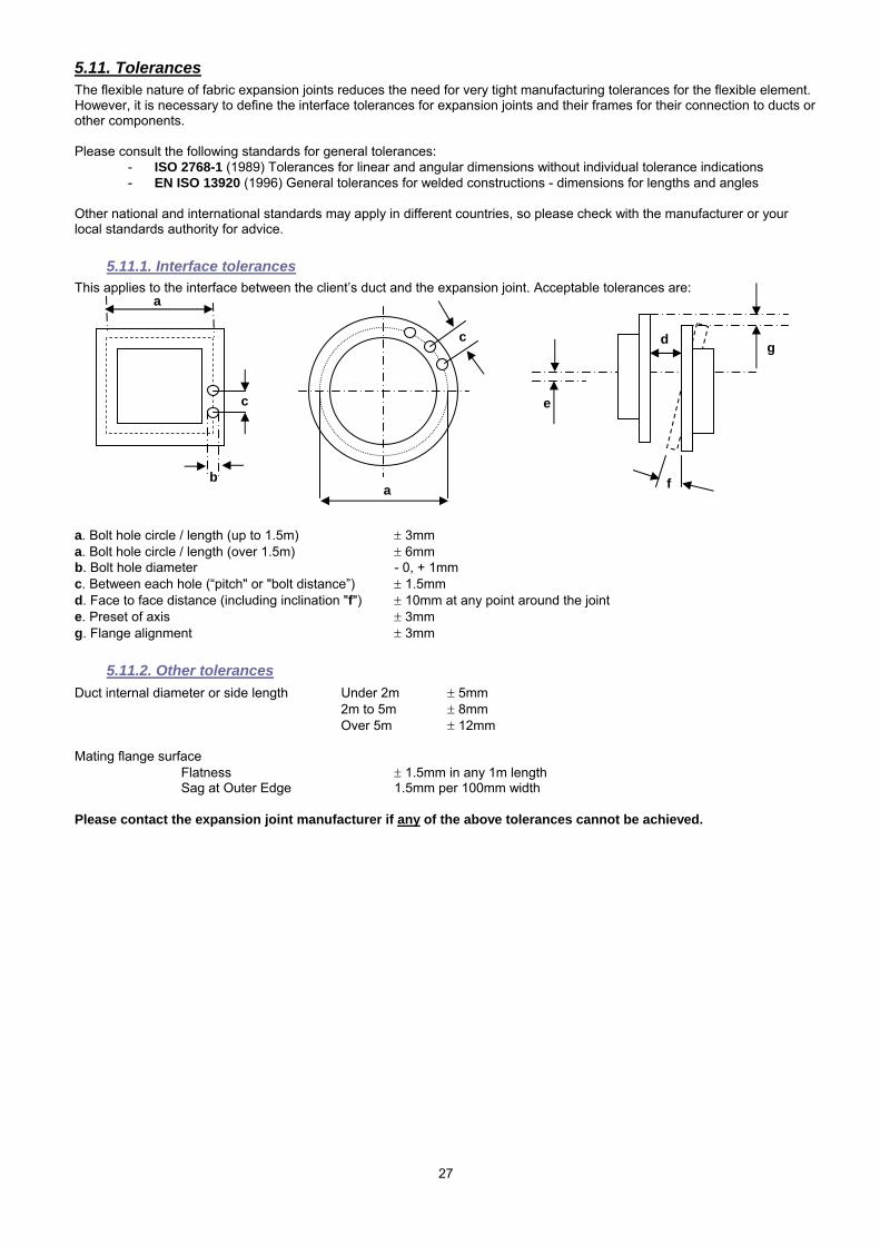
5.11.1. Interface tolerances This applies to the interface between the client’s duct and the expansion joint. Acceptable tolerances are: a. Bolt hole circle / length (up to 1.5m) ± 3mm a. Bolt hole circle / length (over 1.5m) ± 6mm b. Bolt hole diameter - 0, + 1mm c. Between each hole (“pitch" or "bolt distance”) ± 1.5mm d. Face to face distance (including inclination "f") ± 10mm at any point around the joint e. Preset of axis ± 3mm g. Flange alignment ± 3mm
5.11.2. Other tolerances Duct internal diameter or side length Under 2m ± 5mm 2m to 5m ± 8mm
Over 5m ± 12mm Mating flange surface Flatness ± 1.5mm in any 1m length Sag at Outer Edge 1.5mm per 100mm width Please contact the expansion joint manufacturer if any of the above tolerances cannot be achieved.
c
g c
a
e
d
f b a
28
6. Materials A wide variety of materials may be employed, with selection according to the performance requirements of the expansion joint in service. Abrasion resistance, chemical resistance, corrosion resistance, material strength and thermal capability must all be considered. Much of information in this section is courtesy of DuPont Dow, CICIND and the FSA, with thanks.
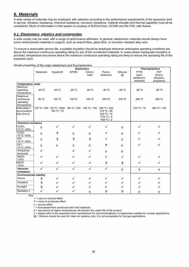
6.1. Elastomers, plastics and composites A wide variety may be used, with a range of performance attributes. In general, elastomeric materials should always have some reinforcement materials in support, such as aramid fibre, glass fibre, or corrosion resistant alloy wire. To ensure a reasonable service life, a suitable insulation should be employed whenever anticipated operating conditions are above the maximum continuous operating rating for any of the constituent materials. In cases where inadequate insulation is provided, temperature excursions above the maximum continuous operating rating are likely to reduce the operating life of the expansion joint. Simple properties of the major elastomers and fluoropolymers:
Elastomers Fluoropolymers Neoprene Hypalon® EPDM Chloro-
butyl Fluoro-
elastomer Silicone
@ PTFE (poly-
tetrafluoro- ethylene)
FEP (fluoro-
ethylene- propylene)
Temperature range Minimum operating temperature
-40 ºC
-40 ºC
-50 ºC
-40 ºC
-40 ºC
-50 ºC
-80 ºC
-80 ºC
Maximum continuous operating temperature
80 ºC
100 ºC
150 ºC
150 ºC
200 ºC
230 ºC
260 ºC
200 ºC
Intermittent / accumulative time (hrs) #
120 ºC / 464 120 ºC / 2600 180 ºC / 70
180 ºC / 200 180 ºC / 150 290 ºC / 240310 ºC / 48 340 ºC / 16 *370 ºC / 4 *400 ºC / 2
370 ºC / 75 260 ºC / 100
Chemical resistance H2SO4 70 ºC <50%
6 6
H2SO4 70 ºC >50%
6 ? 6 6 6 HCl 70 ºC <20%
6 ? ? ? 6 HCl 70 ºC >20%
6 6 6 6 ? 6 Anhydrous ammonia
6 6
NaOH <20%
NaOH >20%
? ? Abrasion resistance
6 6 6 Environmental stability Ozone ? Oxidation ? Sunlight ? Radiation λ 6 ? ? 6 6
Key: = zero or minimal effect
? = minor to moderate effect 6 = severe effect * = fluoroelastomers reinforced with inert materials # = excursions at higher temperatures will shorten the useful life of the product λ = please refer to the expansion joint manufacturer for recommendations on elastomers suitable for nuclear applications@ = Silicone should be used for clean air systems only. It is not acceptable for flue gas applications
29
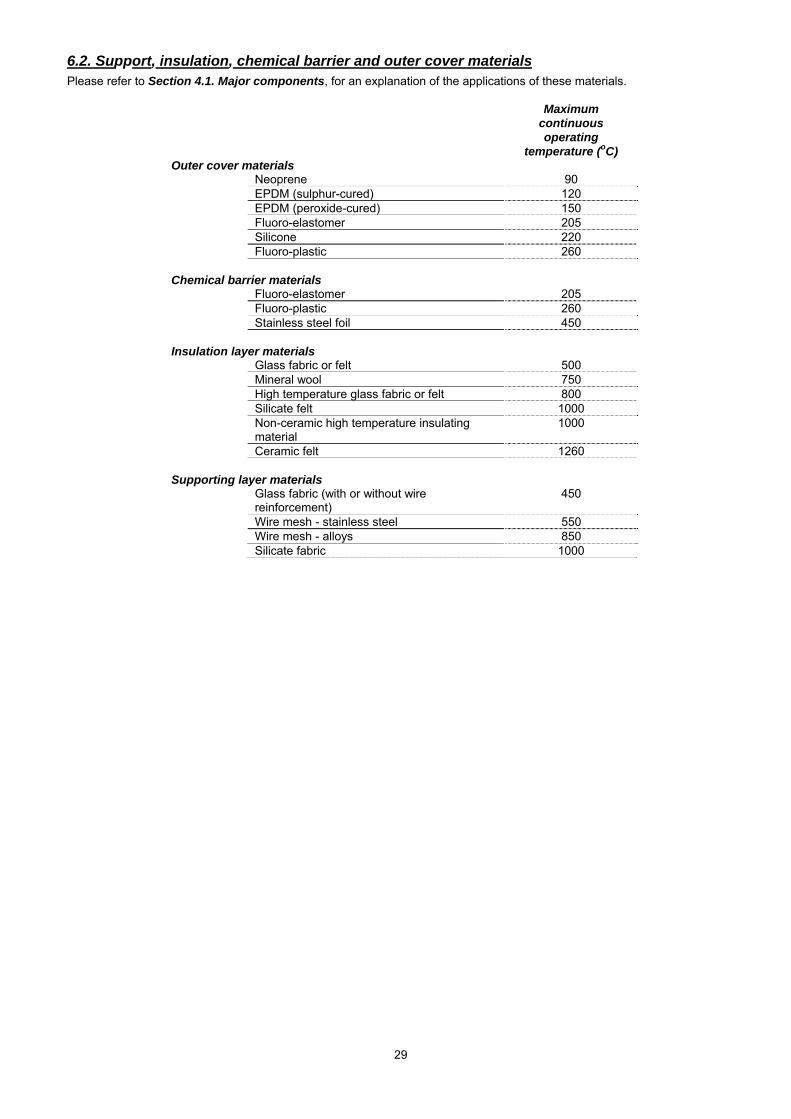
6.2. Support, insulation, chemical barrier and outer cover materials Please refer to Section 4.1. Major components, for an explanation of the applications of these materials.
Maximum continuous operating
temperature (oC) Outer cover materials Neoprene 90 EPDM (sulphur-cured) 120 EPDM (peroxide-cured) 150 Fluoro-elastomer 205 Silicone 220 Fluoro-plastic 260 Chemical barrier materials Fluoro-elastomer 205 Fluoro-plastic 260 Stainless steel foil 450 Insulation layer materials Glass fabric or felt 500 Mineral wool 750 High temperature glass fabric or felt 800 Silicate felt 1000 Non-ceramic high temperature insulating
material 1000
Ceramic felt 1260 Supporting layer materials Glass fabric (with or without wire
reinforcement) 450
Wire mesh - stainless steel 550 Wire mesh - alloys 850 Silicate fabric 1000
30
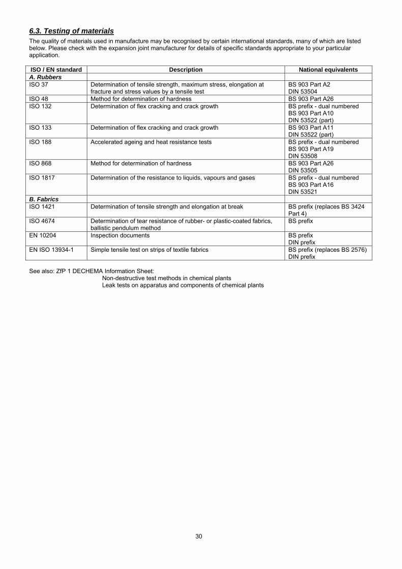
6.3. Testing of materials The quality of materials used in manufacture may be recognised by certain international standards, many of which are listed below. Please check with the expansion joint manufacturer for details of specific standards appropriate to your particular application. ISO / EN standard Description National equivalents A. Rubbers ISO 37 Determination of tensile strength, maximum stress, elongation at
fracture and stress values by a tensile test BS 903 Part A2 DIN 53504
ISO 48 Method for determination of hardness BS 903 Part A26 ISO 132 Determination of flex cracking and crack growth BS prefix - dual numbered
BS 903 Part A10 DIN 53522 (part)
ISO 133 Determination of flex cracking and crack growth BS 903 Part A11 DIN 53522 (part)
ISO 188 Accelerated ageing and heat resistance tests BS prefix - dual numbered BS 903 Part A19 DIN 53508
ISO 868 Method for determination of hardness BS 903 Part A26 DIN 53505
ISO 1817 Determination of the resistance to liquids, vapours and gases BS prefix - dual numbered BS 903 Part A16 DIN 53521
B. Fabrics ISO 1421 Determination of tensile strength and elongation at break BS prefix (replaces BS 3424
Part 4) ISO 4674 Determination of tear resistance of rubber- or plastic-coated fabrics,
ballistic pendulum method BS prefix
EN 10204 Inspection documents BS prefix DIN prefix
EN ISO 13934-1 Simple tensile test on strips of textile fabrics BS prefix (replaces BS 2576) DIN prefix
See also: ZfP 1 DECHEMA Information Sheet: Non-destructive test methods in chemical plants Leak tests on apparatus and components of chemical plants
31
7. Health and safety A variety of fibres, elastomers and fluoroplastics may be used in the production of expansion joint materials. As experience has grown, a number of medical conditions have been ascribed to high exposure to some of these materials. For example, the adverse health effects of exposure to high airborne levels of some fibres (notably asbestos) have been well documented, which has led to the development of a wide range of restrictive legislation. Although it is apparent that health effects vary markedly amongst all the fibre types (even amongst different forms of asbestos), the health effects of many alternative natural and man-made fibres have also been studied increasingly during the last decade. Expansion joint materials Fabric expansion joints with a single ply of elastomer or fluoropolymer reinforced with fibres present no health and safety hazard. Under normal handling and use, it is unlikely that these products will give rise to significant levels of exposure to constituent materials. The fibres are encapsulated usually within an elastomeric binder (or are themselves polymerised), and as such, are unable to enter the human body as airborne dust. Composite expansion joints are manufactured from a variety of fibrous material, either woven or in mat form, and some of these could be irritant or classified as possibly hazardous. Consequently, irrespective of the fibres involved, it is recommended that fibre-containing expansion joint materials should be treated with sufficient care, to avoid the production of unnecessary dust. Equally, when such a material is to be removed or replaced during normal maintenance, always take precautions to minimise dust. In all cases, good standards of hygiene should be applied, and waste materials should be disposed of by transfer to a site which is licensed appropriately to accept industrial materials of this nature. Although the materials are inherently flame resistant, decomposition may occur in some cases at elevated temperatures or in a sustained fire, giving rise to irritant and in some instances harmful or toxic fumes. Materials containing ceramic fibres Expansion joint materials containing ceramic fibres may give rise to harmful dust under harsh mechanical treatment or if the product has been embrittled. Ceramic fibres have been classified by the European Parliament and the Council of Ministers (under the EU Directive 97/69/EC on Classification, Packaging and Labelling of Dangerous Substances of 1997 December 5) as Carcinogenic Category 2 (substances which should be regarded as if they are carcinogenic to man). Occupational exposure to ceramic fibre dust should be minimised and kept well below national exposure limits. Consequently, ESA Members will avoid the use of ceramic materials where a suitable alternative is available - please consult the expansion joint manufacturer for details. Materials containing other fibres These may include a number of fibres, but perhaps especially aramid, glass and man made mineral fibre (MMMF). Most are flame resistant. Some of these fibres (usually of specific diameter) may cause irritation for those with a sensitive skin. Although the majority of these materials are considered non-hazardous, some are under suspicion or are regarded as possibly dangerous. Under the EU Directive 97/69/EC on Classification, Packaging and Labelling of Dangerous Substances of 1997 December 5, most vitreous fibres (stone, glass etc.) have been classified as Carcinogenic Category 3 (substances which cause concern due to possible carcinogenic effects to man), with the exception of those meeting certain exoneration criteria, such as fibre diameter, length or solubility. The aramid, glass, and basalt fibres used in expansion joints generally meet these exoneration criteria. Mineral fibres have been classified as irritant to skin. The classification of vitreous fibres as Carcinogenic Category 3 is in accordance with the classification already in force on the basis of most national regulations in the EU Member States. Occupational exposure to such dusts should be minimised and kept well below national exposure limits. Materials containing fluoroelastomers and fluoroplastics Although these materials are generally non-flammable, decomposition may occur at elevated temperatures or in a sustained fire, giving rise to irritant and in some instances harmful or toxic fumes. Always check with the manufacturer for detailed advice on specific products!
32
8. Transportation, storage, handling for installation and afterwards Part of this section is adapted from the RAL-GZ 719, TI-008 draft, with thanks. Fabric expansion joints are highly engineered products which must be handled with care.
8.1. Packing In the absence of other requirements from the client, fabric expansion joints will be packed in standard, stable cardboard boxes or similar, on pallets which allow removal with a fork lift truck. Special requirements should be agreed with the manufacturer:
• boxes, crates
• seaworthy packing
• overseas container
• special packing
All packing materials are designed for handling with fork lift trucks or cranes. The packing provides the best protection for the expansion joints (in transit and short term storage) and should be removed only at the actual installation location, just prior to installation. Long term storage may require special packing and must be discussed with the manufacturer.
8.2. Transport Fabric expansion joints are packed for transit according to their size, the method and duration of transport, the final shipping destination and the anticipated duration of storage. Damage should not occur during normal transportation. Cardboard boxes on pallets, wooden boxes and containers are designed/suitable for handling by fork lift trucks and cranes, as appropriate. Cardboard boxes on pallets must not be stored on top of each other. The maximum bearing capacity (supporting capacity) must be respected. Unpacked expansion joints should be moved with extreme care. Please note following items:
• unpacked expansion joints must be placed on a secure base (e.g. pallet) and must be protected temporarily during transportation (including on site!)
• the attachment points for the lifting equipment must be on the base (pallet)
• where appropriate, always use several persons for carrying
• do not drag expansion joints along the ground or across edges
• respect decreased bending-properties at low temperatures
8.3. Storage The condition and the duration of storage have an influence on the condition of the expansion joint:
• store expansion joints in original packing
• store expansion joints under dry conditions. Avoid high humidity.
• protect expansion joints from direct weather influence e.g. direct sunlight, rain etc.
• if possible store expansion joints inside buildings
• recommended temperature for storage is between + 10°C to + 20°C
• do not store other equipment on top of the expansion joints
• ozone penetration, chemical influence and aggressive environmental conditions must be avoided for storage longer than 6 months
8.3.1. Short term storage before installation The following additional conditions are recommended:
• store expansion joint in weather-proof container e.g. overseas container
• during short term storage outside, the expansion joint must be covered with an appropriate weather-proof cover and should be protected against dampness from the ground
• at low ambient temperatures, expansion joints have an increased resistance to bending. Under these conditions, it is recommended that the expansion joint should be stored inside a warmer environment immediately prior to installation.
Please contact the supplier in any case where packing is damaged during transport or storage.
33
8.4. Pre-checks prior to installation Please check the following items before installing the expansion joint:
• duct flanges are in a good condition and are fully and continuously welded and free of sharp edges, burrs etc.
• dimensions and holes on duct flanges and clamp bars are correct
• duct flanges are lined up correctly
• clamp bar edges which might touch the flexible materials of the expansion joint are radiused
• where fitted, internal flow sleeves must be in good order and in the correct orientation
For flanged expansion joints, please check in addition: • bolt heads do not damage the outer layers of the expansion joint when expanding
• in confined spaces or when large movements are likely, the clamp bars may need to be fitted with countersunk bolt heads
Never install damaged components!
8.5. Handling for installation To preserve the working life and reliability of the expansion joint, please observe the following precautions:
• large / heavy expansion joints must be supported fully during installation with cranes or pulleys
• fabric expansion joints must not be lifted by attaching the lifting device directly to the fabric. The fabric expansion joint should rest on a supporting base, to which lifting tackles can be attached
• fabric expansion joints which have been pre-assembled by the manufacturer must be lifted by the lifting points and not by their shipping straps (unless the manufacturer has specifically combined the two)
• any protective cover and / or shipping bars must not be removed until installation is completed, but must be removed immediately prior to plant start up
• protect the expansion joint from welding sparks and sharp objects, where appropriate
• do not walk on, or place scaffolding on, the expansion joint
• all clamp bars, including their bolts and nuts, must be in place and hand-tight before tightening further
• required bolt loading will vary, dependent upon the type of expansion joint, bolt dimensions, bolt lubrication, bolt distance etc. Please see Section 5.2 Bolting guidelines for bolted expansion joints.
8.6 After installation When the expansion joint is heated (such as during plant start up), the expansion joint components will settle. Therefore, expansion joint bolts should be re-tightened as soon as possible after start up and not later than at the first shut down. Tighten only to the manufacturer’s recommended bolt torque. Like any other component in an industrial plant, an expansion joint requires supervision to ensure maximum reliability. Expansion joints should be regarded as wearing parts, meaning those parts which need to be replaced at regular intervals. Costly shut downs and emergency situations can often be avoided by replacing wearing parts in a timely fashion. Although, in general, fabric expansion joints do not require actual maintenance, they should be inspected regularly for signs of damage. The first sign of damage will be visible on the surface of the outer cover. The coating may start to discolour or peel, depending on the type of damage (thermal or chemical). If any of these signs appear, contact the expansion joint manufacturer immediately.
34
9. Quality assurance This section is adapted from the FSA Ducting Systems - Technical Handbook 6, with grateful thanks. International standards for quality management systems, such as the ISO 9000 standard, specify requirements for use where a supplier’s capability to design and supply conforming products needs to be demonstrated. The requirements are aimed at achieving customer satisfaction by preventing non-conformity at all stages from design through to servicing. Certification to conformance with the ISO 9000 standard assures verification and documentation of all procedures for managing quality assurance in expansion joint manufacture, from the selection of material through manufacturing, testing and preparation for delivery.
9.1. Identification and control of materials A system shall be used to assure that the materials used in construction of the expansion joint meet the requirements of the drawing, specifications, etc. Documented procedures shall exist for identification and traceability of the materials used for the finished product. For further details of materials testing, please refer to Section 6. Materials. Raw material components and finished parts shall be properly stored and protected to avoid damage.
9.2. Drawing and document control Assembly drawings, when required, shall be made from customer specifications, drawings, purchase order requirements, or other specified information. Documented procedures shall be established to control all documents and data that relate to above documents. When drawing approval is required by the purchaser, the manufacturer shall submit drawings showing basic dimensions, operating conditions, movements, materials and other related information. The manufacturer shall maintain a record of all purchase approved drawings and specifications, which shall identify the current revision status of all documents.
9.3. Manufacturing processes and control A system shall be used to ensure that only the applicable drawings and procedures are employed in manufacture. The manufacturer shall document procedures for production, installation and servicing processes to ensure uniform and constant product quality.
9.4. Testing, inspection and documentation Each manufacturer shall prepare, maintain and use written procedures covering the in-process and inspection operations that are used in the course of manufacturing methods, dimensional checks, visual inspections, non-destructive tests and other pertinent operations that are to be performed to assure that the expansion joint meets the specifications. The procedure shall specify the applicable acceptance standards and shall provide for a means to document that operations have in fact been performed and the results determined to be satisfactory.
9.4.1. Physical testing Since flue gas expansion joints are so large, it is virtually impossible to set up an in-plant testing procedure for each expansion joint in situ as the cost of such a testing program would be prohibitive compared to the value gained. Small leakage in an installation is normally acceptable. Structural pressure tests are not normally practical and are not recommended. Materials used in the manufacture of the expansion joints shall be tested for quality assurance and written procedures shall be established to record the findings. The product shall be checked at each manufacturing step to assure a product capable of performing satisfactorily in its recommended service. The manufacturer shall establish and maintain records which document that the product has been inspected and/or tested, and whether the expansion joint has passed or failed the inspections and/or tests.
9.4.2. Thermal testing On request, manufacturers can provide test data demonstrating the ability of the overall design and combination of materials to withstand the maximum temperature for which the expansion joint is proposed. Attention is drawn particularly to the clamping area, where temperature considerations are important and should be discussed thoroughly with the manufacturer.
6 Ducting Systems - Technical Handbook (3rd edition), published by the Fluid Sealing Association, 1997.
35
9.4.3. Tightness For recommendations on bolt loading, please see Section 5.2. Bolting guidelines for bolted expansion joints. The information in this section is specific for Germany, and is provided as an example only, courtesy of the RAL (other national and international standards may apply in different countries, so please check with the manufacturer or your local standards authority for advice). Using the fastening method selected by the manufacturer and with the flange surface specified by him, the expansion joint must be tight in both the flexible length and clamping area. “Flue-gas tight” as used here is defined by the latest edition of the DECHEMA Information Sheet ZfP1, Supplementary Sheet 2, Paragraph 2.2: Bubble method with foaming liquid (“nekal-tight“). The definition of nekal-tight applies to the entire, installed expansion joint. For more information on these RAL technical definitions, please see Section 11. Flue-gas and nekal tightness.
9.5. Final inspection and preparation for shipment Prior to shipment, the following items of an expansion joint should be checked to ensure maximum integrity of the product:
(a) dimensional compliance with manufacturing drawings, including flange bolt pattern (if applicable) ( b) integrity of splices in the flexible element (if applicable) (c) security of nuts and bolts on clamp bars, flange assemblies, and shipping straps or restraining hardware (d) adequate size, number, and placement of shipping straps, lifting points, or installation aids (painted yellow if removal is required after installing) (e) expansion joint assemblies with internal flow sleeves should be shipped and stored with up-stream end uppermost to help prevent accumulation of rainwater (f) identification markings, flow direction arrows, and instruction should be clearly stenciled or permanently affixed (g) installation instructions should be included with each assembly (h) general condition of flexible element, frame and paint in accordance with customer requirements and good manufacturing practices
36
10. Warranties & liabilities Fabric expansion joints are usually considered to be a critical component of the systems within which they work. As such, premature or unplanned failure can often result in serious inefficiencies or dangerous leaks. Consequently, expansion joint performance, and the manufacturers support of its performance, is a matter for serious consideration. Although important components, fabric expansion joints often cost only a small fraction of the overall system costs or the costs of losses due to downtime for replacement following unplanned failure. However, it must be emphasised that expansion joints are wearing parts with a finite life and, as such, should be subject to an inspection routine. The risk of failure increases as operating life extends. It is always preferable for installation to be under the close supervision of the expansion joint manufacturer, to ensure that the correct procedures are applied. Obviously there is a cost associated with this service. Not only will the installation be performed correctly, but also the expertise of such teams usually ensures a much quicker installation process, with associated lower lifetime costs for the client. In the event that a performance warranty is provided and installation has been made by third parties following only written / schematic instructions provided by the manufacturer, it is important that the completed installation is inspected and approved by the manufacturer or his nominee prior to accepting the warranty conditions. In no event will consequential system losses be admitted as a liability due to premature failure. The level of warranty should be clearly agreed between the manufacturer and the client prior to execution of the contract. Irrespective of the level of warranty accepted, specified operating conditions must be agreed by both parties. If these conditions are exceeded, for any reason, the warranty may be void. Expansion joint manufacturers will warrant their products for defective workmanship or materials, usually against a given time-span (typically 12 months), agreed with the client. Replacement or repair (whichever is deemed appropriate by the manufacturer) will be limited to the scope and terms of original supply.
10.1. Commencement period Warranty periods need to be defined (typically 12 months or 8000 operating hours) and agreed; whether they begin at delivery on site, start-up or after commissioning. The period may be expressed in terms of years, months or operating hours.
10.2. Warranty claims Claims are dependent on how quickly the manufacturer is advised of the problem; a minor defect requiring a small repair may become a major replacement if appropriate action is not taken in a timely fashion. Part of the warranty negotiation may include annual inspections paid for by the customer, allowing the manufacturer to inspect the installation.
10.3. Extended warranties In cases when warranties are agreed over a few years, then after the initial warranty period (typically 12 months) when 100% of the warranty will be honoured, a sliding scale may operate to reflect that some of the working life of the expansion joint has occurred. Extended warranties are likely to be charged at a premium. Specific clauses should be negotiated with the manufacturer at the time of the contract review.
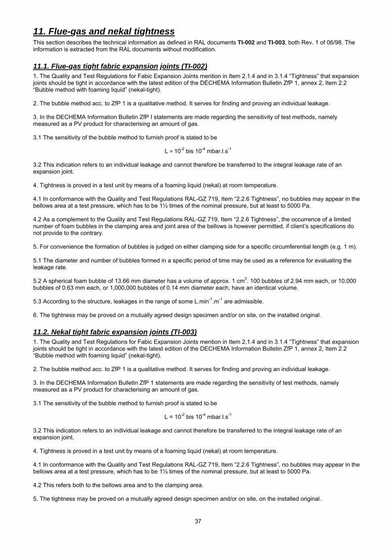
37
11. Flue-gas and nekal tightness This section describes the technical information as defined in RAL documents TI-002 and TI-003, both Rev. 1 of 06/98. The information is extracted from the RAL documents without modification.
11.1. Flue-gas tight fabric expansion joints (TI-002) 1. The Quality and Test Regulations for Fabic Expansion Joints mention in Item 2.1.4 and in 3.1.4 “Tightness” that expansion joints should be tight in accordance with the latest edition of the DECHEMA Information Bulletin ZfP 1, annex 2, Item 2.2 “Bubble method with foaming liquid” (nekal-tight). 2. The bubble method acc. to ZfP 1 is a qualitative method. It serves for finding and proving an individual leakage. 3. In the DECHEMA Information Bulletin ZfP I statements are made regarding the sensitivity of test methods, namely measured as a PV product for characterising an amount of gas. 3.1 The sensitivity of the bubble method to furnish proof is stated to be
L = 10-2 bis 10-4 mbar.l.s-1 3.2 This indication refers to an individual leakage and cannot therefore be transferred to the integral leakage rate of an expansion joint. 4. Tightness is proved in a test unit by means of a foaming liquid (nekal) at room temperature. 4.1 In conformance with the Quality and Test Regulations RAL-GZ 719, Item “2.2.6 Tightness”, no bubbles may appear in the bellows area at a test pressure, which has to be 1½ times of the nominal pressure, but at least to 5000 Pa. 4.2 As a complement to the Quality and Test Regulations RAL-GZ 719, Item “2.2.6 Tightness”, the occurrence of a limited number of foam bubbles in the clamping area and joint area of the bellows is however permitted, if client’s specifications do not provide to the contrary. 5. For convenience the formation of bubbles is judged on either clamping side for a specific circumferential length (e.g. 1 m). 5.1 The diameter and number of bubbles formed in a specific period of time may be used as a reference for evaluating the leakage rate. 5.2 A spherical foam bubble of 13.66 mm diameter has a volume of approx. 1 cm3. 100 bubbles of 2.94 mm each, or 10,000 bubbles of 0.63 mm each, or 1,000,000 bubbles of 0.14 mm diameter each, have an identical volume. 5.3 According to the structure, leakages in the range of some L.min-1.m-1 are admissible. 6. The tightness may be proved on a mutually agreed design specimen and/or on site, on the installed original.
11.2. Nekal tight fabric expansion joints (TI-003) 1. The Quality and Test Regulations for Fabic Expansion Joints mention in Item 2.1.4 and in 3.1.4 “Tightness” that expansion joints should be tight in accordance with the latest edition of the DECHEMA Information Bulletin ZfP 1, annex 2, Item 2.2 “Bubble method with foaming liquid” (nekal-tight). 2. The bubble method acc. to ZfP 1 is a qualitative method. It serves for finding and proving an individual leakage. 3. In the DECHEMA Information Bulletin ZfP 1 statements are made regarding the sensitivity of test methods, namely measured as a PV product for characterising an amount of gas. 3.1 The sensitivity of the bubble method to furnish proof is stated to be
L = 10-2 bis 10-4 mbar.l.s-1 3.2 This indication refers to an individual leakage and cannot therefore be transferred to the integral leakage rate of an expansion joint. 4. Tightness is proved in a test unit by means of a foaming liquid (nekal) at room temperature. 4.1 In conformance with the Quality and Test Regulations RAL-GZ 719, Item “2.2.6 Tightness”, no bubbles may appear in the bellows area at a test pressure, which has to be 1½ times of the nominal pressure, but at least to 5000 Pa. 4.2 This refers both to the bellows area and to the clamping area. 5. The tightness may be proved on a mutually agreed design specimen and/or on site, on the installed original.
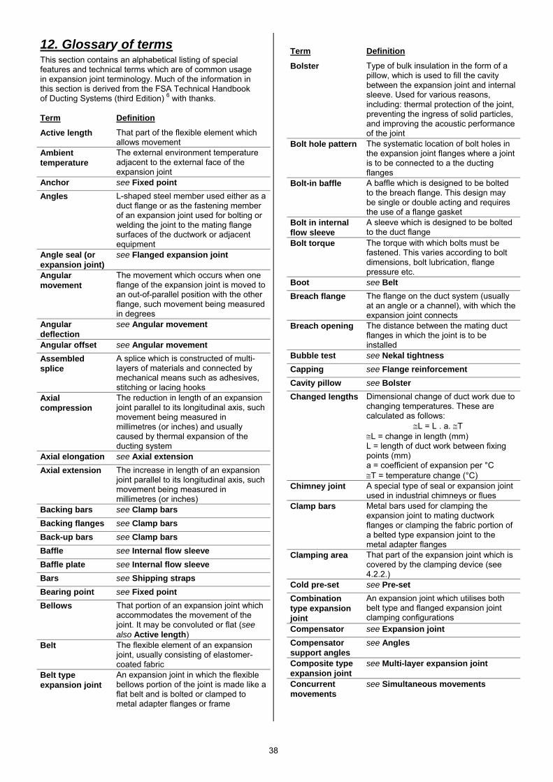
38
12. Glossary of terms This section contains an alphabetical listing of special features and technical terms which are of common usage in expansion joint terminology. Much of the information in this section is derived from the FSA Technical Handbook of Ducting Systems (third Edition) 6 with thanks. Term Definition
Active length That part of the flexible element which allows movement
Ambient temperature
The external environment temperature adjacent to the external face of the expansion joint
Anchor see Fixed point Angles L-shaped steel member used either as a
duct flange or as the fastening member of an expansion joint used for bolting or welding the joint to the mating flange surfaces of the ductwork or adjacent equipment
Angle seal (or expansion joint)
see Flanged expansion joint
Angular movement
The movement which occurs when one flange of the expansion joint is moved to an out-of-parallel position with the other flange, such movement being measured in degrees
Angular deflection
see Angular movement
Angular offset see Angular movement Assembled splice
A splice which is constructed of multi-layers of materials and connected by mechanical means such as adhesives, stitching or lacing hooks
Axial compression
The reduction in length of an expansion joint parallel to its longitudinal axis, such movement being measured in millimetres (or inches) and usually caused by thermal expansion of the ducting system
Axial elongation see Axial extension Axial extension The increase in length of an expansion
joint parallel to its longitudinal axis, such movement being measured in millimetres (or inches)
Backing bars see Clamp bars Backing flanges see Clamp bars Back-up bars see Clamp bars Baffle see Internal flow sleeve Baffle plate see Internal flow sleeve Bars see Shipping straps Bearing point see Fixed point Bellows That portion of an expansion joint which
accommodates the movement of the joint. It may be convoluted or flat (see also Active length)
Belt The flexible element of an expansion joint, usually consisting of elastomer-coated fabric
Belt type expansion joint
An expansion joint in which the flexible bellows portion of the joint is made like a flat belt and is bolted or clamped to metal adapter flanges or frame
Term Definition
Bolster Type of bulk insulation in the form of a pillow, which is used to fill the cavity between the expansion joint and internal sleeve. Used for various reasons, including: thermal protection of the joint, preventing the ingress of solid particles, and improving the acoustic performance of the joint
Bolt hole pattern The systematic location of bolt holes in the expansion joint flanges where a joint is to be connected to a the ducting flanges
Bolt-in baffle A baffle which is designed to be bolted to the breach flange. This design may be single or double acting and requires the use of a flange gasket
Bolt in internal flow sleeve
A sleeve which is designed to be bolted to the duct flange
Bolt torque The torque with which bolts must be fastened. This varies according to bolt dimensions, bolt lubrication, flange pressure etc.
Boot see Belt Breach flange The flange on the duct system (usually
at an angle or a channel), with which the expansion joint connects
Breach opening The distance between the mating duct flanges in which the joint is to be installed
Bubble test see Nekal tightness Capping see Flange reinforcement Cavity pillow see Bolster Changed lengths Dimensional change of duct work due to
changing temperatures. These are calculated as follows: ≅L = L . a. ≅T ≅L = change in length (mm) L = length of duct work between fixing points (mm) a = coefficient of expansion per °C ≅T = temperature change (°C)
Chimney joint A special type of seal or expansion joint used in industrial chimneys or flues
Clamp bars Metal bars used for clamping the expansion joint to mating ductwork flanges or clamping the fabric portion of a belted type expansion joint to the metal adapter flanges
Clamping area That part of the expansion joint which is covered by the clamping device (see 4.2.2.)
Cold pre-set see Pre-set Combination type expansion joint
An expansion joint which utilises both belt type and flanged expansion joint clamping configurations
Compensator see Expansion joint Compensator support angles
see Angles
Composite type expansion joint
see Multi-layer expansion joint
Concurrent movements
see Simultaneous movements
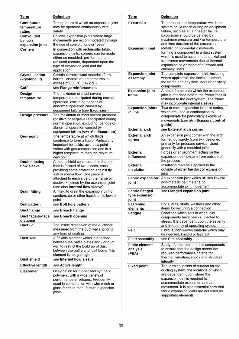
39
Term Definition
Continuous temperature rating
Temperature at which an expansion joint may be operated continuously with safety
Convoluted bellows expansion joint
Bellows expansion joints where large movements are accommodated through the use of convolutions or “vees”
Corners In connection with rectangular fabric expansion joints, corners can be made either as moulded, pre-formed, or radiused corners, dependent upon the type of expansion joint and the application
Crystallisation (krystoballit)
Certain ceramic wool materials form harmful crystals at temperatures in excess of 800 °C (1472 °F)
Cuff see Flange reinforcement Design temperature
The maximum or most severe temperature anticipated during normal operation, excluding periods of abnormal operation caused by equipment failure (see Excursion)
Design pressure The maximum or most severe pressure (positive or negative) anticipated during normal operation, excluding periods of abnormal operation caused by equipment failure (see also Excursion)
Dew point The temperature at which fluids condense to form a liquid. Particularly important for acids; acid dew point varies with gas composition and is a higher temperature than the moisture dew point
Double-acting flow sleeve
A metal shield constructed so that the liner is formed of two pieces, each providing some protection against fly ash or media flow. One piece is attached to each side of the frame or ductwork, joined by the expansion joint (see also Internal flow sleeve)
Drain fitting A fitting to drain the expansion joint of condensate or other liquids at its lowest point
Drill pattern see Bolt hole pattern Duct flange see Breach flange Duct face-to-face distance
see Breach opening
Duct i.d. The inside dimension of the ductwork measured from the duct walls, prior to any form of coating
Dust seal A flexible element which is attached between the baffle plates and / or duct wall to restrict the build up of dust between the baffle and joint body. This element is not gas tight
Dust shield see Internal flow sleeve Effective length see Active length Elastomer Designation for rubber and synthetic
polymers, with a wide variety of performance envelopes. Frequently used in combination with wire mesh or glass fabric to manufacture expansion joints
Term Definition
Excursion The pressure or temperature which the system could reach during an equipment failure, such as an air heater failure. Excursions should be defined by maximum pressure and / or temperature and time duration of the excursion
Expansion joint Metallic or non-metallic materials forming a component in a duct system which is used to accommodate axial and transverse movements due to thermal expansion or vibration of ductwork and chimney liners
Expansion joint assembly
The complete expansion joint, including, where applicable, the flexible element, the frame and any flow liners or ancillary components
Expansion joint frame
A metal frame onto which the expansion joint is attached before the frame itself is fastened to the duct system. The frame may incorporate internal sleeves
Expansion joints in line
Two or more expansion joints in series, which are used in combination to compensate for particularly excessive movements (see also Scissors control guide)
External arch see External arch corner External arch corner
An expansion joint corner with the arch formed outwardly (convex), designed primarily for pressure service. Used generally with a moulded joint
External influences
Forces or environment acting on the expansion joint system from outside of the process
External insulation
Insulation materials applied to the outside of either the duct or expansion joint
Fabric expansion joint
An expansion joint which utilises flexible non-metallic belt material to accommodate joint movement
Fabric flanged type expansion joint
see Flanged expansion joint
Fastening elements
Bolts, nuts, studs, washers and other items for securing a connection
Fatigue Condition which sets in when joint components have been subjected to stress. It is dependent upon the severity and frequency of operating cycles.
Felt Fibrous, non-woven material which may be needled, knitted or layered
Field assembly see Site assembly Finite element analysis (FEA)
Study of a structure and its components to ensure that the design meets the required performance criteria for thermal, vibration, shock and structural integrity
Fixed point The terminal points of support for the ducting system, the locations of which are dependent upon where the expansion joint is required to accommodate expansion and / or movement. It is also essential here that fabric expansion joints are not used as supporting elements
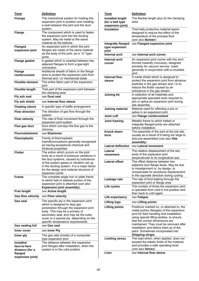
40
Term Definition Fixings The mechanical system for holding the
expansion joint in position and creating a seal between the joint and the duct system
Flange The component which is used to fasten the expansion joint into the ducting system. May be metal or the same material as the bellows
Flanged expansion joint
An expansion joint in which the joint flanges are made of the same material as the body of the joint, as in “U” type joints
Flange gasket A gasket which is inserted between two adjacent flanges to form a gas-tight connection
Flange reinforcement
Additional sheath of fabric in the flange area to protect the expansion joint from thermal and / or mechanical loads
Flexible element The entire fabric part of the expansion joint
Flexible length That part of the expansion joint between the clamping area
Fly ash seal see Dust seal Fly ash shield see Internal flow sleeve
Floating sleeve A specific type of baffle arrangement
Flow direction The direction of gas flow through the system
Flow velocity The rate of fluid movement through the expansion joint system
Flue gas duct Duct which conveys the flue gas to the chimney
Fluoroelastomer see Elastomer Fluoroplastic Family of thermoplastic
hydrofluorocarbons generally recognised as having exceptional chemical and frictional properties
Flutter The action which occurs on the joint body as a result of pressure variations in the duct systems, caused by turbulence of the system gases or vibration set up in the ducting system. It is a major factor for the design and material structure of expansion joints
Frame The complete angle iron or plate frame to which belt or bellows portion of the expansion joint is attached (see also Expansion joint assembly)
Free length see Active length Gas flow velocity see Flow velocity Gas seal The specific ply in the expansion joint
which is designed to stop gas penetration through the expansion joint body. This may be a primary or secondary seal, and may be the outer cover or a special ply, depending on the specific temperature requirements
Gas sealing foil see Gas seal Inner cover see Inner Ply Inner ply The gas side (inside) of a composite
type expansion joint Installed face-to-face distance (for a flanged expansion joint)
The distance between the expansion joint flanges after installation, when the system is in the cold position
Term Definition Installed length (for a belt type expansion joint)
The flexible length plus 2x the clamping area
Insulation Thermally protective material layers designed to reduce the effect of the temperature of the process fluid (see also Bolster)
Integrally flanged type expansion joint
see Flanged expansion joint
Internal arch see Internal arch corner Internal arch corner
An expansion joint corner with the arch formed inwardly (concave), designed primarily for vacuum service. Used generally in conjunction with a moulded joint
Internal flow sleeve
A metal shield which is designed to protect the expansion joint from abrasive particles in the gas stream and / or to reduce the flutter caused by air turbulence in the gas stream
Joining kit A collection of all materials and appropriate specialist tools required to join or splice an expansion joint during site assembly
Joining material Material used for effecting a join or splice in an expansion joint
Joint cuff see Flange reinforcement Joint framing Metallic frame to which belted or
integrally flanged joints are attached before installation
Knock down form
The assembly of the joint at the job site, usually as a result of it being too large to ship pre-assembled (see also Site assembly)
Lateral deflection see Lateral movement Lateral movement
The relative displacement of the two ends of the expansion joint perpendicular to its longitudinal axis
Lateral offset The offset distance between two adjacent duct flange faces. May be due to misalignment or, by design, to compensate for excessive displacement in the opposite direction during cycling
Leakage rate The rate of fluid leaking through the expansion joint or flange area
Life cycles The number of times the expansion joint is operated from cold to hot position and then back to cold again
Life expectancy see Fatigue Lifting lugs see Lifting points Lifting points Positions marked on, or attached to, the
metal portion (flanges) of the expansion joint for field handling and installation using special lifting tackles, to ensure that the correct dimensions are maintained. They must be removed after installation and before start-up of the plant. Sometimes incorporated into Shipping straps
Limiting stress The load which, when applied, does nor exceed the elastic limits of the material and provides a safe operating level (see also Stress)
Liner see Internal flow sleeve
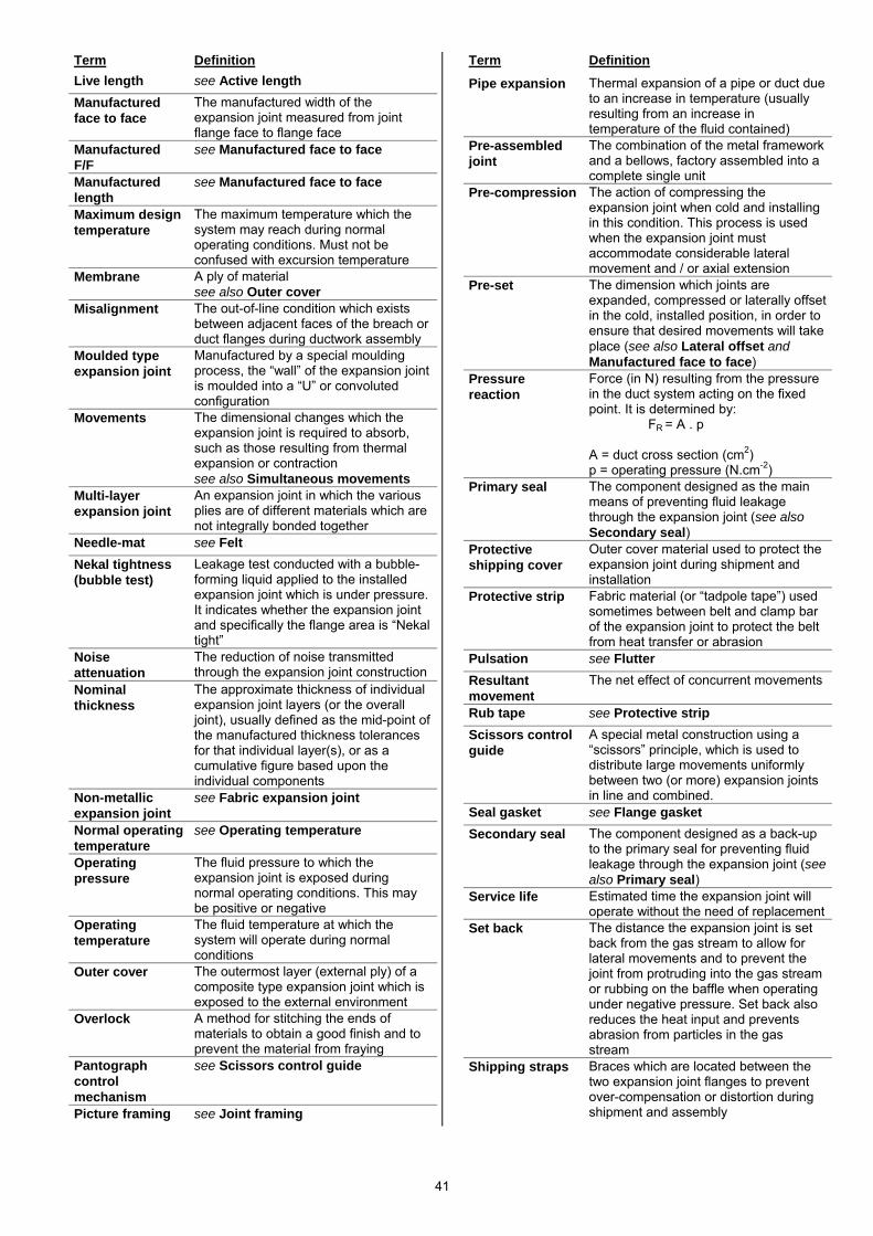
41
Term Definition Live length see Active length Manufactured face to face
The manufactured width of the expansion joint measured from joint flange face to flange face
Manufactured F/F
see Manufactured face to face
Manufactured length
see Manufactured face to face
Maximum design temperature
The maximum temperature which the system may reach during normal operating conditions. Must not be confused with excursion temperature
Membrane A ply of material see also Outer cover
Misalignment The out-of-line condition which exists between adjacent faces of the breach or duct flanges during ductwork assembly
Moulded type expansion joint
Manufactured by a special moulding process, the “wall” of the expansion joint is moulded into a “U” or convoluted configuration
Movements The dimensional changes which the expansion joint is required to absorb, such as those resulting from thermal expansion or contraction see also Simultaneous movements
Multi-layer expansion joint
An expansion joint in which the various plies are of different materials which are not integrally bonded together
Needle-mat see Felt Nekal tightness (bubble test)
Leakage test conducted with a bubble-forming liquid applied to the installed expansion joint which is under pressure. It indicates whether the expansion joint and specifically the flange area is “Nekal tight”
Noise attenuation
The reduction of noise transmitted through the expansion joint construction
Nominal thickness
The approximate thickness of individual expansion joint layers (or the overall joint), usually defined as the mid-point of the manufactured thickness tolerances for that individual layer(s), or as a cumulative figure based upon the individual components
Non-metallic expansion joint
see Fabric expansion joint
Normal operating temperature
see Operating temperature
Operating pressure
The fluid pressure to which the expansion joint is exposed during normal operating conditions. This may be positive or negative
Operating temperature
The fluid temperature at which the system will operate during normal conditions
Outer cover The outermost layer (external ply) of a composite type expansion joint which is exposed to the external environment
Overlock A method for stitching the ends of materials to obtain a good finish and to prevent the material from fraying
Pantograph control mechanism
see Scissors control guide
Picture framing see Joint framing
Term Definition
Pipe expansion Thermal expansion of a pipe or duct due to an increase in temperature (usually resulting from an increase in temperature of the fluid contained)
Pre-assembled joint
The combination of the metal framework and a bellows, factory assembled into a complete single unit
Pre-compression The action of compressing the expansion joint when cold and installing in this condition. This process is used when the expansion joint must accommodate considerable lateral movement and / or axial extension
Pre-set The dimension which joints are expanded, compressed or laterally offset in the cold, installed position, in order to ensure that desired movements will take place (see also Lateral offset and Manufactured face to face)
Pressure reaction
Force (in N) resulting from the pressure in the duct system acting on the fixed point. It is determined by: FR = A . p A = duct cross section (cm2) p = operating pressure (N.cm-2)
Primary seal The component designed as the main means of preventing fluid leakage through the expansion joint (see also Secondary seal)
Protective shipping cover
Outer cover material used to protect the expansion joint during shipment and installation
Protective strip Fabric material (or “tadpole tape”) used sometimes between belt and clamp bar of the expansion joint to protect the belt from heat transfer or abrasion
Pulsation see Flutter Resultant movement
The net effect of concurrent movements
Rub tape see Protective strip Scissors control guide
A special metal construction using a “scissors” principle, which is used to distribute large movements uniformly between two (or more) expansion joints in line and combined.
Seal gasket see Flange gasket Secondary seal The component designed as a back-up
to the primary seal for preventing fluid leakage through the expansion joint (see also Primary seal)
Service life Estimated time the expansion joint will operate without the need of replacement
Set back The distance the expansion joint is set back from the gas stream to allow for lateral movements and to prevent the joint from protruding into the gas stream or rubbing on the baffle when operating under negative pressure. Set back also reduces the heat input and prevents abrasion from particles in the gas stream
Shipping straps Braces which are located between the two expansion joint flanges to prevent over-compensation or distortion during shipment and assembly
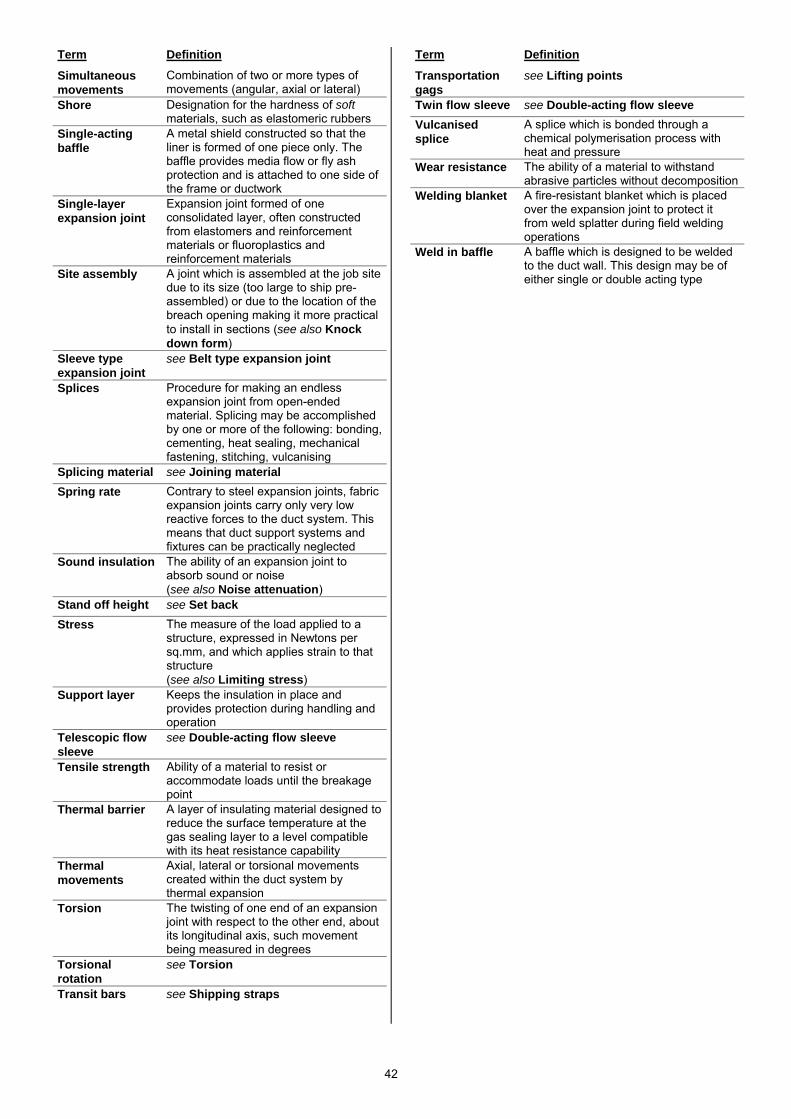
42
Term Definition
Simultaneous movements
Combination of two or more types of movements (angular, axial or lateral)
Shore Designation for the hardness of soft materials, such as elastomeric rubbers
Single-acting baffle
A metal shield constructed so that the liner is formed of one piece only. The baffle provides media flow or fly ash protection and is attached to one side of the frame or ductwork
Single-layer expansion joint
Expansion joint formed of one consolidated layer, often constructed from elastomers and reinforcement materials or fluoroplastics and reinforcement materials
Site assembly A joint which is assembled at the job site due to its size (too large to ship pre-assembled) or due to the location of the breach opening making it more practical to install in sections (see also Knock down form)
Sleeve type expansion joint
see Belt type expansion joint
Splices Procedure for making an endless expansion joint from open-ended material. Splicing may be accomplished by one or more of the following: bonding, cementing, heat sealing, mechanical fastening, stitching, vulcanising
Splicing material see Joining material Spring rate Contrary to steel expansion joints, fabric
expansion joints carry only very low reactive forces to the duct system. This means that duct support systems and fixtures can be practically neglected
Sound insulation The ability of an expansion joint to absorb sound or noise (see also Noise attenuation)
Stand off height see Set back Stress The measure of the load applied to a
structure, expressed in Newtons per sq.mm, and which applies strain to that structure (see also Limiting stress)
Support layer Keeps the insulation in place and provides protection during handling and operation
Telescopic flow sleeve
see Double-acting flow sleeve
Tensile strength Ability of a material to resist or accommodate loads until the breakage point
Thermal barrier A layer of insulating material designed to reduce the surface temperature at the gas sealing layer to a level compatible with its heat resistance capability
Thermal movements
Axial, lateral or torsional movements created within the duct system by thermal expansion
Torsion The twisting of one end of an expansion joint with respect to the other end, about its longitudinal axis, such movement being measured in degrees
Torsional rotation
see Torsion
Transit bars see Shipping straps
Term Definition
Transportation gags
see Lifting points
Twin flow sleeve see Double-acting flow sleeve Vulcanised splice
A splice which is bonded through a chemical polymerisation process with heat and pressure
Wear resistance The ability of a material to withstand abrasive particles without decomposition
Welding blanket A fire-resistant blanket which is placed over the expansion joint to protect it from weld splatter during field welding operations
Weld in baffle A baffle which is designed to be welded to the duct wall. This design may be of either single or double acting type
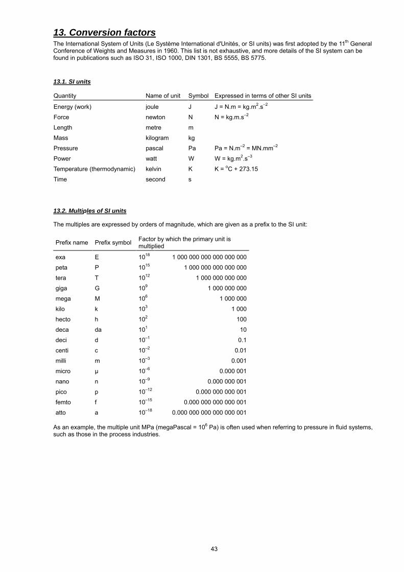
43
13. Conversion factors The International System of Units (Le Système International d'Unités, or SI units) was first adopted by the 11th General Conference of Weights and Measures in 1960. This list is not exhaustive, and more details of the SI system can be found in publications such as ISO 31, ISO 1000, DIN 1301, BS 5555, BS 5775. 13.1. SI units Quantity Name of unit Symbol Expressed in terms of other SI units Energy (work)
joule J J = N.m = kg.m2.s–2
Force newton N N = kg.m.s–2
Length metre m
Mass kilogram kg
Pressure pascal Pa Pa = N.m–2 = MN.mm–2
Power watt W W = kg.m2.s–3
Temperature (thermodynamic) kelvin K K = oC + 273.15
Time second s 13.2. Multiples of SI units The multiples are expressed by orders of magnitude, which are given as a prefix to the SI unit:
Prefix name Prefix symbol Factor by which the primary unit is multiplied
exa
E
1018
1 000 000 000 000 000 000
peta P 1015 1 000 000 000 000 000
tera T 1012 1 000 000 000 000
giga G 109 1 000 000 000
mega M 106 1 000 000
kilo k 103 1 000
hecto h 102 100
deca da 101 10
deci d 10–1 0.1
centi c 10–2 0.01
milli m 10–3 0.001
micro μ 10–6 0.000 001
nano n 10–9 0.000 000 001
pico p 10–12 0.000 000 000 001
femto f 10–15 0.000 000 000 000 001
atto a 10–18 0.000 000 000 000 000 001 As an example, the multiple unit MPa (megaPascal = 106 Pa) is often used when referring to pressure in fluid systems, such as those in the process industries.
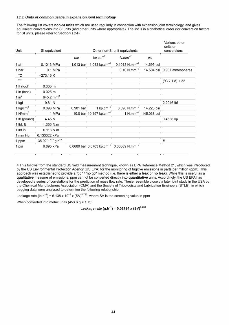
44
13.3. Units of common usage in expansion joint terminology The following list covers non-SI units which are used regularly in connection with expansion joint terminology, and gives equivalent conversions into SI units (and other units where appropriate). The list is in alphabetical order (for conversion factors for SI units, please refer to Section 13.4):
Unit SI equivalent Other non-SI unit equivalents
Various other units or conversions
bar kp.cm–2 N.mm–2 psi
1 at
0.1013
MPa
1.013 bar
1.033 kp.cm–2 0.1013 N.mm–2 14.695 psi
1 bar 0.1 MPa 0.10 N.mm–2 14.504 psi 0.987 atmospheres 1 oC –273.15 K 1 oF (oC x 1.8) + 32 1 ft (foot) 0.305 m 1 in (inch) 0.025 m 1 in2 645.2 mm2 1 kgf 9.81 N 2.2046 lbf 1 kg/cm2 0.098 MPa 0.981 bar 1 kp.cm–2 0.098 N.mm–2 14.223 psi 1 N/mm2 1 MPa 10.0 bar 10.197 kp.cm–2 1 N.mm–2 145.038 psi 1 lb (pound) 4.45 N 0.4536 kp 1 lbf. ft 1.355 N.m 1 lbf.in 0.113 N.m 1 mm Hg 0.133322 kPa 1 ppm 35.92–0.733 g.h–1 # 1 psi 6.895 kPa 0.0689 bar 0.0703 kp.cm–2 0.00689 N.mm–2 # This follows from the standard US field measurement technique, known as EPA Reference Method 21, which was introduced by the US Environmental Protection Agency (US EPA) for the monitoring of fugitive emissions in parts per million (ppm). This approach was established to provide a ”go'' / “no go'' method (i.e. there is either a leak or no leak). While this is useful as a qualitative measure of emissions, ppm cannot be converted directly into quantitative units. Accordingly, the US EPA has developed a series of correlations for the prediction of mass flow rate. These resemble closely a later joint study in the USA by the Chemical Manufacturers Association (CMA) and the Society of Tribologists and Lubrication Engineers (STLE), in which bagging data were analysed to determine the following relationship:
Leakage rate (lb.h–1) = 6.138 x 10⁻⁵ x (SV)0.733, where SV is the screening value in ppm
When converted into metric units (453.6 g = 1 lb):
Leakage rate (g.h–1) = 0.02784 x (SV)0.733
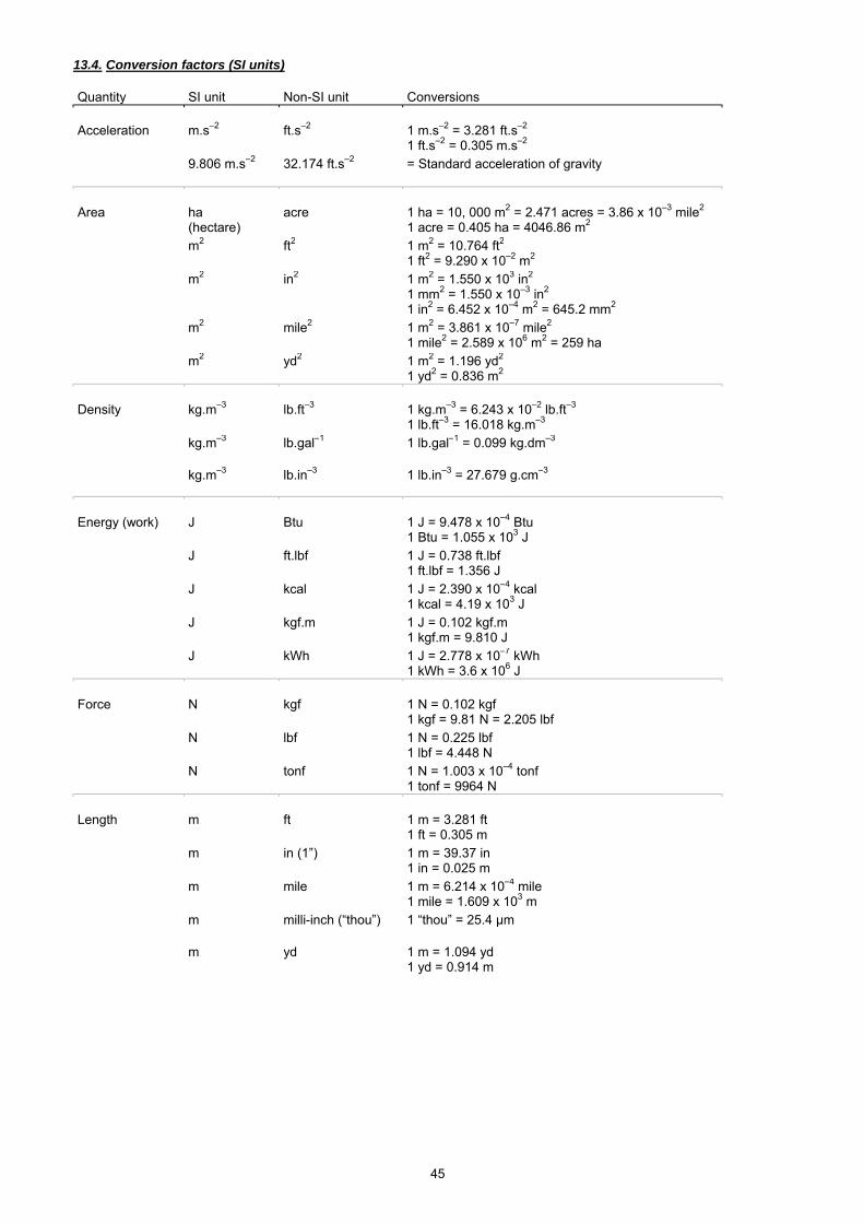
45
13.4. Conversion factors (SI units) Quantity SI unit Non-SI unit Conversions Acceleration
m.s–2
ft.s–2
1 m.s–2 = 3.281 ft.s–2 1 ft.s–2 = 0.305 m.s–2
9.806 m.s–2 32.174 ft.s–2 = Standard acceleration of gravity
Area
ha (hectare)
acre
1 ha = 10, 000 m2 = 2.471 acres = 3.86 x 10⁻³ mile2 1 acre = 0.405 ha = 4046.86 m2
m2 ft2 1 m2 = 10.764 ft2 1 ft2 = 9.290 x 10⁻² m2
m2 in2 1 m2 = 1.550 x 10³ in2 1 mm2 = 1.550 x 10⁻³ in2 1 in2 = 6.452 x 10⁻⁴ m2 = 645.2 mm2
m2 mile2 1 m2 = 3.861 x 10⁻⁷ mile2 1 mile2 = 2.589 x 10⁶ m2 = 259 ha
m2 yd2 1 m2 = 1.196 yd2 1 yd2 = 0.836 m2
Density
kg.m–3
lb.ft–3
1 kg.m–3 = 6.243 x 10⁻² lb.ft–3 1 lb.ft–3 = 16.018 kg.m–3
kg.m–3 lb.gal–1 1 lb.gal–1 = 0.099 kg.dm–3
kg.m–3 lb.in–3 1 lb.in–3 = 27.679 g.cm–3
Energy (work)
J
Btu
1 J = 9.478 x 10⁻⁴ Btu 1 Btu = 1.055 x 10³ J
J ft.lbf 1 J = 0.738 ft.lbf 1 ft.lbf = 1.356 J
J kcal 1 J = 2.390 x 10⁻⁴ kcal 1 kcal = 4.19 x 10³ J
J kgf.m 1 J = 0.102 kgf.m 1 kgf.m = 9.810 J
J kWh 1 J = 2.778 x 10⁻⁷ kWh 1 kWh = 3.6 x 10⁶ J
Force
N
kgf
1 N = 0.102 kgf 1 kgf = 9.81 N = 2.205 lbf
N lbf 1 N = 0.225 lbf 1 lbf = 4.448 N
N tonf 1 N = 1.003 x 10⁻⁴ tonf 1 tonf = 9964 N
Length
m
ft
1 m = 3.281 ft 1 ft = 0.305 m
m in (1”) 1 m = 39.37 in 1 in = 0.025 m
m mile 1 m = 6.214 x 10⁻⁴ mile 1 mile = 1.609 x 10³ m
m milli-inch (“thou”) 1 “thou” = 25.4 μm
m yd 1 m = 1.094 yd 1 yd = 0.914 m
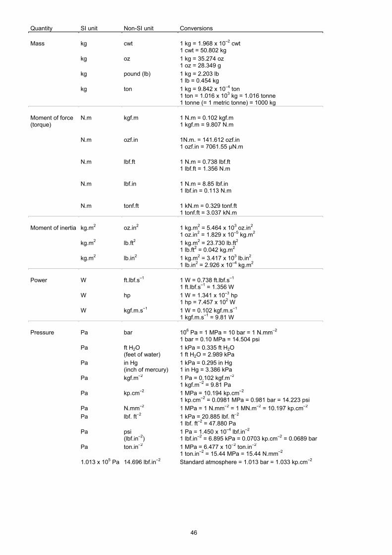
46
Quantity SI unit Non-SI unit Conversions Mass
kg
cwt
1 kg = 1.968 x 10⁻² cwt 1 cwt = 50.802 kg
kg oz 1 kg = 35.274 oz 1 oz = 28.349 g
kg pound (lb) 1 kg = 2.203 lb 1 lb = 0.454 kg
kg ton 1 kg = 9.842 x 10⁻⁴ ton 1 ton = 1.016 x 10³ kg = 1.016 tonne 1 tonne (= 1 metric tonne) = 1000 kg
Moment of force (torque)
N.m
kgf.m
1 N.m = 0.102 kgf.m 1 kgf.m = 9.807 N.m
N.m
ozf.in
1N.m. = 141.612 ozf.in 1 ozf.in = 7061.55 μN.m
N.m
lbf.ft
1 N.m = 0.738 lbf.ft 1 lbf.ft = 1.356 N.m
N.m
lbf.in
1 N.m = 8.85 lbf.in 1 lbf.in = 0.113 N.m
N.m
tonf.ft
1 kN.m = 0.329 tonf.ft 1 tonf.ft = 3.037 kN.m
Moment of inertia
kg.m2
oz.in2
1 kg.m2 = 5.464 x 10³ oz.in2 1 oz.in2 = 1.829 x 10⁻⁵ kg.m2
kg.m2 lb.ft2 1 kg.m2 = 23.730 lb.ft2 1 lb.ft2 = 0.042 kg.m2
kg.m2 lb.in2 1 kg.m2 = 3.417 x 10³ lb.in2 1 lb.in2 = 2.926 x 10⁻⁴ kg.m2
Power
W
ft.lbf.s–1
1 W = 0.738 ft.lbf.s–1 1 ft.lbf.s–1 = 1.356 W
W hp 1 W = 1.341 x 10⁻³ hp 1 hp = 7.457 x 10² W
W kgf.m.s–1 1 W = 0.102 kgf.m.s–1 1 kgf.m.s–1 = 9.81 W
Pressure
Pa
bar
106 Pa = 1 MPa = 10 bar = 1 N.mm–2 1 bar = 0.10 MPa = 14.504 psi
Pa ft H2O (feet of water)
1 kPa = 0.335 ft H2O 1 ft H2O = 2.989 kPa
Pa in Hg (inch of mercury)
1 kPa = 0.295 in Hg 1 in Hg = 3.386 kPa
Pa kgf.m–2 1 Pa = 0.102 kgf.m–2 1 kgf.m–2 = 9.81 Pa
Pa kp.cm–2 1 MPa = 10.194 kp.cm–2 1 kp.cm–2 = 0.0981 MPa = 0.981 bar = 14.223 psi
Pa N.mm–2 1 MPa = 1 N.mm–2 = 1 MN.m–2 = 10.197 kp.cm–2 Pa lbf. ft–2 1 kPa = 20.885 lbf. ft–2
1 lbf. ft–2 = 47.880 Pa
Pa psi (lbf.in–2)
1 Pa = 1.450 x 10⁻⁴ lbf.in–2 1 lbf.in–2 = 6.895 kPa = 0.0703 kp.cm–2 = 0.0689 bar
Pa ton.in–2 1 MPa = 6.477 x 10⁻² ton.in–2 1 ton.in–2 = 15.44 MPa = 15.44 N.mm–2
1.013 x 10⁵ Pa 14.696 lbf.in–2 Standard atmosphere = 1.013 bar = 1.033 kp.cm–2
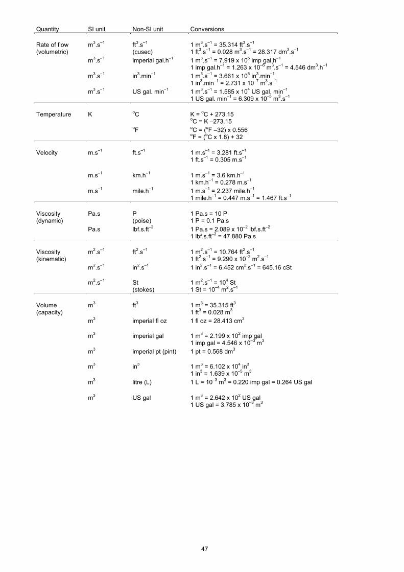
47
Quantity SI unit Non-SI unit Conversions Rate of flow (volumetric)
m3.s–1
ft3.s–1 (cusec)
1 m3.s–1 = 35.314 ft3.s–1 1 ft3.s–1 = 0.028 m3.s–1 = 28.317 dm3.s–1
m3.s–1 imperial gal.h–1 1 m3.s–1 = 7.919 x 10⁵ imp gal.h–1 1 imp gal.h–1 = 1.263 x 10⁻⁶ m3.s–1 = 4.546 dm3.h–1
m3.s–1 in3.min–1 1 m3.s–1 = 3.661 x 10⁶ in3.min–1 1 in3.min–1 = 2.731 x 10⁻⁷ m3.s–1
m3.s–1 US gal. min–1 1 m3.s–1 = 1.585 x 10⁴ US gal. min–1 1 US gal. min–1 = 6.309 x 10⁻⁵ m3.s–1
Temperature
K
oC
K = oC + 273.15 oC = K –273.15
oF oC = (oF –32) x 0.556 oF = (oC x 1.8) + 32
Velocity
m.s–1
ft.s–1
1 m.s–1 = 3.281 ft.s–1 1 ft.s–1 = 0.305 m.s–1
m.s–1
km.h–1
1 m.s–1 = 3.6 km.h–1 1 km.h–1 = 0.278 m.s–1
m.s–1 mile.h–1 1 m.s–1 = 2.237 mile.h–1 1 mile.h–1 = 0.447 m.s–1 = 1.467 ft.s–1
Viscosity (dynamic)
Pa.s
P (poise)
1 Pa.s = 10 P 1 P = 0.1 Pa.s
Pa.s lbf.s.ft–2
1 Pa.s = 2.089 x 10⁻² lbf.s.ft–2 1 lbf.s.ft–2 = 47.880 Pa.s
Viscosity (kinematic)
m2.s–1
ft2.s–1
1 m2.s–1 = 10.764 ft2.s–1 1 ft2.s–1 = 9.290 x 10⁻² m2.s–1
m2.s–1 in2.s–1 1 in2.s–1 = 6.452 cm2.s–1 = 645.16 cSt
m2.s–1 St (stokes)
1 m2.s–1 = 104 St 1 St = 10–4 m2.s–1
Volume (capacity)
m3
ft3
1 m3 = 35.315 ft3 1 ft3 = 0.028 m3
m3 imperial fl oz 1 fl oz = 28.413 cm3
m3 imperial gal 1 m3 = 2.199 x 10² imp gal 1 imp gal = 4.546 x 10⁻³ m3
m3 imperial pt (pint) 1 pt = 0.568 dm3
m3 in3 1 m3 = 6.102 x 10⁴ in3 1 in3 = 1.639 x 10⁻⁵ m3
m3 litre (L) 1 L = 10–3 m3 = 0.220 imp gal = 0.264 US gal
m3 US gal 1 m3 = 2.642 x 10² US gal 1 US gal = 3.785 x 10⁻³ m3

48
14. References 1. USA Regulations on Fugitive Emissions (ESA Report No. 003/94), published by the European Sealing Association, 1994. 2. European Emission Legislation (ESA Publication No. 012/00), published by the European Sealing Association, 2000. 3. Test specification RAL TI-002 Rev. 1 – 06/98 Flue-Gas Tight Fabric Expansion Joints refers to leak tight as “…no bubbles may appear in the bellows area…” and that “…the occurrence of a limited number of foam bubbles in the clamping area and joint area of the bellows is however permitted…”. 4. Test specification RAL TI-003 Rev. 1 – 06/98 Nekal Tight Fabric Expansion Joints refers to nekal tight as “…no bubbles may appear in the bellows area…” and that “…this refers to both the bellows area and to the clamping area…”. 5. Test methods similar to DECHEMA Information Bulletin ZfP 1, annex 2 Item 2.2 “Bubble method with foaming liquid”. 6. Ducting Systems - Technical Handbook (3rd edition), published by the Fluid Sealing Association, 1997.