Embed Size (px)
Citation preview

B&W FUEL COMPANY, COMMERCIAL NUCLEAR FUEL PLANT MODEL B FRESH FUEL SHIPPING CONTAINER
PACKAGE ID USA/6206/AF I DOCKET 71-6206 SECTION: SAFETY ANALYSIS REPORT
EXHIBIT B
REPORT ON TEST OF
MODEL B FRESH FUEL SHIPPING CONTAINER
PART A - MINOR DROP TESTS, SHIPPING & HANDLING TESTS
PART B - 30' DROP TESTS AND PIN DROP
TESTS PERFORMED BY
CONTAINER RESEARCH CORPORATION Hallow Hill Road
Glen Riddle, Penna.
9508090216 950731 PDR ADOCK 07106206 C PDR
1 DATE: 07-31-95 REV: 5PAGE: EXHIBIT B -

B&W FUEL COMPANY, COMMERCIAL NUCLEAR FUEL PLANT
MODEL B FRESH FUEL SHIPPING CONTAINER
PACKAGE ID USA/6206/AF I DOCKET 71-6206
SECTION: SAFETY ANALYSIS REPORT
Part A of Exhibit B
MINOR DROP TESTS, SHIPPING AND HANDLING TEST
REV: 52 DATE: 07-31-95PAGE: EXHIBIT B -

B&W FUEL COMPANY, COMMERCIAL NUCLEAR FUEL PLANT
MODEL B FRESH FUEL SHIPPING CONTAINER
PACKAGE ID USA/6206/AF I DOCKET 71-6206 SECTION: SAFETY ANALYSIS REPORT
EXHIBIT B
PART A
TABLE OF CONTENTS
SECTION
1.0
2.0
3.0
4.0 4.2
5.0 5.1.2 5.2
6.0 6.2 6.3 6.4 6.5 6.6 6.7 6.8 6.9 6.10 6.11 6.12 6.13 6.14
7.0
TITLE
Purpose
Conclusions
Recommendations
Container Description Physical Data
Method of Test Deviations Instrumentation
Tests
PAGE
B-4
B-4
B-4
B-4 B-6
B-6 B-6 B-7
B-8 B-8 B-9 B-9 B-9 B-Il B-lI B-lI B-lI B-l1 B-li B-12 B-14 B-14
B-15
Flat Drop Edge Drop Corner Drop Rollover Impact-Pendulum Hoisting Forklift Towing Stacking Fuel Ass'y Load/Unload Demo. Shipping Flat Drop Edge Drop
Container Modifications
DATE: 07-31-95PAGE: EXHIBIT B -
REV: 53

B&W FUEL COMPANY, COMMERCIAL NUCLEAR FUEL PLANT MODEL B FRESH FUEL SHIPPING CONTAINER
PACKAGE ID USA/6206/AF I DOCKET 71-6206 SECTION: SAFETY ANALYSIS REPORT
EXHIBIT B
1.0 PURPOSE:
The purpose of the test described herein are to verify
conformance to BABCOCK & WILCOCK COMPANY Equipment
Specification CS-3-83 dated 2/28/69 and Drawing Number
208R001. (The current drawings are PE-52F, PE-53F, and PE
54F).
2.0 CONCLUSIONS:
2.1 A complete series of tests was successfully performed with all design requirements adequately satisfied and with only a few minor changes resulting to improve reliability. These changes are described in detail under test results.
2.2 The tests were witnessed by BABCOCK & WILCOX Technical Representatives as well as CONTAINER RESEARCH CORPORATION Quality Control Personnel and it was
concluded that the container will provide adequate protection for the fuel cells during normal shipment, handling, and storage.
3.0 RECOMMENDATIONS:
3.1 It is recommended that the Model B fresh fuel shipping container be granted approval for shipment of
production fresh fuel cells.
4.0 CONTAINER DESCRIPTION:
4.1 The shipping container was designed for transportation of either one or two fresh fuel cells.
4.1.1 The cells are clamped securely to a frame suspended on 18 shockmounts. The frame is made up of two separate sections with the upper section capable of pivoting about one end to a vertical position in
which the fuel cells are loaded and unloaded.
4.1.2 A series of hinged clamps (clamp bows) are used to secure the fuel cell to the frame prior to lowering the frame to a
horizontal position. A suspension system lockout feature and storable external outriggers provide stability of the container during load/unload sequence.
. . A n 07-31-Q5 REV: 5P~AGEi: r1Aflnj±±L 0 -

B&W FUEL COMPANY, COMMERCIAL NUCLEAR FUEL PLANT
MODEL B FRESH FUEL SHIPPING CONTAINER PACKAGE ID USA/6206/AF I DOCKET 71-6206
SECTION: SAFETY ANALYSIS REPORT
4.1.3 There shall be a clamp bow to restrain
each spacer grid and end fitting. The
ratio of assembly weight to the number of
clamp bows shall not exceed 168 lbs.
Positioning the clamp bows on the spacer
grids and end fittings provides for
uniform restraint along the length of the
fuel assembly. The spacer grids provide
the support needed to maintain the fuel
rods in position which is crucial in
maintaining proper coolant flow, heat
transfer, and reactivity control. The
ratio of assembly weight to the number of
clamp bows noted above is based on the
number of clamp bows and the weight of
the dummy fuel assembly used in the
original as dropped configuration. Ten
clamp bows were used to hold a 1680 lb.
dummy fuel assembly during the original
drop tests. This therefore yields a
ratio of 168 lbs. per clamp bow which
justified the use of less than 10 clamp
bows provided as the dropped ratio of 168
lbs./clamp bow is not exceeded.
4.1.4 The basic container structure consists of
.089 steel sheet skin and .124 steel
flanged end plates. Sealing is achieved
with structural steel angles 2 x 3 x
1/4". A 1/2" "0" ring type gasket is
used between the container and closure
lid. This gasket is placed in a fitted
groove around the circumference of the
container.
4.1.5 Two steel angles 3 x 3 by 3/8" attached
to the base of the container provide
reinforcement and forklift features as
well as a means of attaching four (4)
hardwood skids. Rollover angles and
braces are also provided to reinforce
certain areas of the base and cover.
4.1.6 Stacking features include four (4)
brackets on the container cover which
permit stacking like containers one
directly above the other, as well as,
side by side placement of two bottom
containers with a third upper container
straddling both in a pyramid manner.
4.1.7 Other features include a dessicant
- 5 DATE: 07-31-95 REV:5PAGE: EXHIBIT B -

B&W FUEL COMPANY, COMMERCIAL NUCLEAR FUEL PLANT
MODEL B FRESH FUEL SHIPPING CONTAINER PACKAGE ID USA/6206/AF I DOCKET 71-6206
SECTION: SAFETY ANALYSIS REPORT
basket, humidity indicator, dessicant
access port, automatic/manual two way
breather valve, four view ports (two each
end) for inspection of mechanical
accelerometers mounted to suspend frame,
and an air filling valve at the opposite
end of the container from the breather
valve which may be used for inert gas
purging.
4.2 PHYSICAL DATA:
CONTAINER SIZE: length = 205" width = 44 1/2" height = 47 1/4"
CUBAGE: cu. ft. = 250
AS TESTED WEIGHTS: Container & Frame 3940-lbs. Fresh Fuel Cells (2) 3000-lbs. Gross (Shipping) 6940-lbs.
5.0 METHOD OF TEST:
5.1 GENERAL:
Two dummy fuel cells were provided by BABCOCK & WILCOX
COMPANY for the purpose of conducting a series of
tests.
Also provided were four (4) weights of 150 lbs. each.
These were added internally to the dummy fuel cells
increasing the weight of each to 1800 lbs. for
additional tests.
5.1.1 An edgewise rotational drop from a height
of eighteen (18) inches was then
performed to test the ability of the
container suspension system to withstand the increased loading.
5.1.2 A test procedure (CRC-PTP-3799) written
by CONTAINER RESEARCH CORPORATION and
approved by BABCOCK & WILCOX, approved
deviations. The deviations are outlined
below and described fully in detail in
Section 7 under Container Modifications:
TEST PROCEDURE DEVIATIONS:
A) Hoisting Test - Electronic
n -11. r% REV: 5PAGE: EXHIBIT B - b UM.L *
B&W FUEL COMPANY, COMMERCIAL NUCLEAR FUEL PLANT
MODEL B FRESH FUEL SHIPPING CONTAINER PACKAGE ID USA/6206/AF I DOCKET 71-6206
SECTION: SAFETY ANALYSIS REPORT
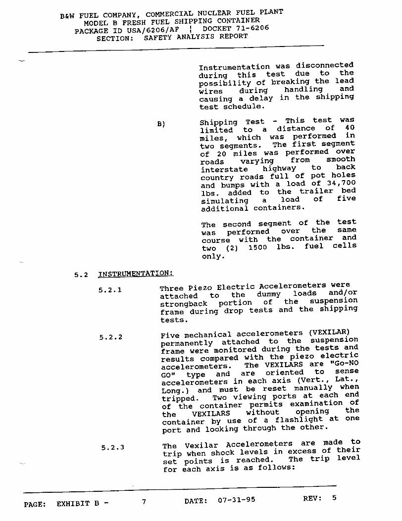
Instrumentation was disconnected during this test due to the possibility of breaking the lead wires during handling and causing a delay in the shipping test schedule.
B) Shipping Test - This test was
limited to a distance of 40 miles, which was performed in two segments. The first segment of 20 miles was performed over roads varying from smooth interstate highway to back country roads full of pot holes and bumps with a load of 34,700 lbs. added to the trailer bed
simulating a load of five additional containers.
The second segment of the test was performed over the same course with the container and two (2) 1500 lbs. fuel cells only.
5.2 INSTRUMENTATION:
5.2.1 Three Piezo Electric Accelerometers were
attached to the dummy loads and/or
strongback portion of the suspension
frame during drop tests and the shipping tests.
5.2.2 Five mechanical accelerometers (VEXILAR) permanently attached to the suspension
frame were monitored during the tests and
results compared with the piezo electric
accelerometers. The VEXILARS are "Go-NO
GO" type and are oriented to sense
accelerometers in each axis (Vert., Lat.,
Long.) and must be reset manually when
tripped. Two viewing ports at each end
of the container permits examination of
the VEXILARS without opening the
container by use of a flashlight at one
port and looking through the other.
5.2.3 The Vexilar Accelerometers are made to
trip when shock levels in excess of their
set points is reached. The trip level
for each axis is as follows:
7 DATE: 07-31-95 REV : 5PAGE: EXHIBIT B -

B&W FUEL COMPANY, COMMERCIAL NUCLEAR FUEL PLANT
MODEL B FRESH FUEL SHIPPING CONTAINER PACKAGE ID USA/6206/AF I DOCKET 71-6206
SECTION: SAFETY ANALYSIS REPORT
A) VERTICAL AXIS 11 G's Tolerence of vexilars is +
10%
B) LATERAL AXIS 10 G's
C) LONGITUDINAL AXIS 8 G's
5.2.4 Modeling clay was placed in critical
areas of the container during tests to
determine frame deflections as well as
determining the exact length of
deformable pin type deflection indicators, which will be attached at
various locations on the frame during
each shipment of fuel cells. The pins
will be used to detect in conjunction
with the VEXILARS, excursions and shock
levels in excess of allowable levels
which may have occurred in transit.
5.2.5 Calibration - The Piezo Electric
Accelerometers and Associated Electronics
were calibrated in accordance with MIL-C45662A.
6.0 TESTS:
6.1 GENERAL:
Tests were conducted in accordance with CRC-PTP-3799
Rev. A Issue Date: 11/5/69 Preproduction Test
Procedure. Data derived from each test requiring
instrumentation is recorded on individual data sheets
including accelerometer locations.
6.2 FLAT DROP: (with two 1500 lbs. dummy fuel cells)
6.2.1 The loaded container was raised and
allowed to fall freely to the floor from
a height of 10 inches to a concrete
surface, landing flat on its bottom.
6.2.1.1 RESULTS: No Damage - Data Acceptable.
6.3 EDGE DROP: (with two 1500 lbs. dummy fuel cells)
6.3.1 One end of the container was supported by
a 5 inch high block of wood placed at
right angles to the skids. The opposite
end was raised and allowed to fall freely
to the floor from a height of 20 inches.
8 DATE: 07-31-95PAGE: EXHIBIT B -
REV: 5

B&W FUEL COMPANY, COMMERCIAL NUCLEAR FUEL PLANT
MODEL B FRESH FUEL SHIPPING CONTAINER PACKAGE ID USA/6206/AF I DOCKET 71-6206
SECTION: SAFETY ANALYSIS REPORT
6.3.2 This test was applied to the opposite end
of the container also.
6.3.2.1 RESULTS: No Damage - Data Acceptable.
6.4 CORNER DROP: (with two 1500 lbs. dummy fuel cells)
6.4.1 The container was supported at one corner
of its base on a 5 inch high block with a
12 inch high block under the other corner
at the same end. The opposite end corner
"A" was raised and allowed to fall freely
to the floor from a height of 12 inches
and 24 inches. The cover was removed
after the 24 inch drop and the contents
were examined.
6.4.1.1 RESULTS: No Damage - Data Acceptable but
the bottom corner of the frame had cut
through the clay and marked the finish on
the container skin. This is not
considered serious since the shock level
was within acceptable limits.
6.4.2CORNER DROP:(with two 1500 lbs. dummy fuel cells)
6.4.2.1 This test performed in same manner as
6.4.1 with same results except corner "C"
was impacted.
6.5 ROLLOVER TEST: (with two 1500 lbs. dummy fuel cells)
6.5.1 The container was tipped slowly over from
its base to its left side, left side to
top, top to right side, and right side to
base for a total of 360 degrees.
6.5.1.1 RESULTS: No Damage - Data Acceptable.
6.6 IMPACT. (with two 1500 lbs. dummy fuel cells)
6.6.1 The container was suspended as a pendulum
from four steel straps, pulled back until
the center of gravity had been raised 18
inches above its rest position, and
released to impact into a rigid barrier
with the skids taking the full force of
impact. This test was applied to the AFT
END.
6.6.1.1 RESULTS: No Damage - Data Acceptable
........ L Ln -u 9 DATE: 07-31-95 REV: 5P'AaL•: Z•Arlno. V.

B&W FUEL COMPANY, COMMERCIAL NUCLEAR FUEL PLANT MODEL B FRESH FUEL SHIPPING CONTAINER
PACKAGE ID USA/6206/AF I DOCKET 71-6206 SECTION: SAFETY ANALYSIS REPORT
6.6.2 The impact test was applied to the FWD
END of the container also, but upon
examination of the oscillograph trace it
was discovered that although the pulse
exhibited ideal characteristics such as, low amplitude (maximum of 8 G's), and
normal duration (.120 seconds) there was
a short duration spike (.005 seconds)
riding the peak of the fundamental with
an amplitude of two G's bringing the peak
acceleration to 10 G's. This was an
indication that something on the
suspended mass had moved and bottomed out.
6.6.2.1 Upon inspection of the opened container it was determined that the screw jacks on the end gate of the frame had not been properly tightened against the end of the fuel cells. They had obviously been hung up on two or three threads, which were designed for retention of the screw jacks only and when the force from the fuel cells exceeded the strength of the threads, the threads stripped causing the fuel cells to shift until they were positively restrained by the load bearing threads. The end gate liner material was also changed at this time from cork to 60 DURO. NEOPRENE.
6.6.2.2 The container was closed and the impact test repeated with accelerometers relocated from the frame strongback to the top of the dummy fuel cells.
6.6.2.3 RESULTS: There was no damage and the data was within acceptable limits.
6.6.2.4 The corrective action for this condition will be to redesign the screw jack retention method. (See Section 6 CONTAINER MODIFICATIONS).
PAE: ...... TE: 0J - -7-31-95 REV: 5PAGE: EXHIBIT B -
B&W FUEL COMPANY, COMMERCIAL NUCLEAR FUEL PLANT
MODEL B FRESH FUEL SHIPPING CONTAINER
PACKAGE ID USA/6206/AF I DOCKET 71-6206 SECTION: SAFETY ANALYSIS REPORT
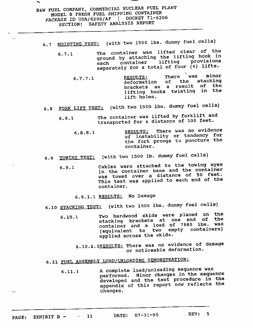
6.7 HOISTING TEST: (with two 1500 lbs. dummy fuel cells)
6.7.1 The container was lifted clear of the
ground by attaching the lifting hook in
each container lifting provisions separately for a total of four (4) lifts.
6.7.7.1 RESULTS: There was minor deformation of the stacking brackets as a result of the lifting hooks twisting in the lift holes.
6.8 FORK LIFT TEST: (with two 1500 lbs. dummy fuel cells)
6.8.1 The container was lifted by forklift and
transported for a distance of 100 feet.
6.8.8.1 RESULTS: There was no evidence of instability or tendency for the fork prongs to puncture the container.
6.9 TOWING TEST: (with two 1500 lb. dummy fuel cells)
6.9.1 Cables were attached to the towing eyes
in the container base and the container was towed over a distance of 50 feet.
This test was applied to each end of the
container.
6.9.1.1 RESULTS: No Damage
6.10 STACKING TEST: (with two 1500 lbs. dummy fuel cells)
6.10.1 Two hardwood skids were placed on the
stacking brackets at one end of the
container and a load of 7880 lbs. was
(equivalent to two empty containers) applied across the skids.
6.10.1.1RESULTS: There was no evidence of damage
or noticeable deformation.
6.11 FUEL ASSEMBLY LOAD/UNLOADING DEMONSTRATION:
6.11.1 A complete load/unloading sequence was
performed. Minor changes in the sequence
developed and the test procedure in the
appendix of this report now reflects the changes.
11 DATE: 07-31-95PAGE: EXHIBIT B -
REV: 5

B&W FUEL COMPANY, COMMERCIAL NUCLEAR FUEL PLANT MODEL B FRESH FUEL SHIPPING CONTAINER
PACKAGE ID USA/6206/AF I DOCKET 71-6206 SECTION: SAFETY ANALYSIS REPORT
6.11.2 A record of time (man hours) are recorded in the data log.
6.12 SHIPPING TEST: (with two 1500 lbs. dummy fuel cells)
UNSCHEDULED 48" INVERTED DROP - During preparation for
the shipping *test the loaded container was placed
aboard a flat bed truck for transporting outside the
building for transfer to a flat bed trailer.
The container was placed on the center of the truck
bed with an overhead hoist and once outside the
forklift operator attempted to lift the container.
Not realizing that the forks did not extend far enough
to completely engage the container, he attempted to
lift the container rapidly, causing the container to
roll over on to its side and off the truck bed to the
ground (approximately a 48" drop). The container
landed on its cover resulting in a distorted stacking
bracket, which was the only external damage.
In trying to upright the container to its base the
driver placed the fork prongs against the cover skin
and lifted, not realizing that the container weight
6940 lbs. with the dummy fuel cells inside.
The result was that the cover skin was caved in by the
prongs.
At this time the driver notified the test engineer who
then brought the container back inside the building
where it was opened and the contents examined.
Since the clay had been installed in preparation for
the road test, it was possible to determine the
effects of the 48" inverted drop as far as deflections
and shock were concerned.
The following results were noted:
A) The cover skin had been caved in by the
forklift prongs approximately 3 inches over a 48 inch span on one side. This was hammered out before start of the shipping test.
B) AFT END - This was the end, which
received the initial impact from the fall
and the minimum remaining clearance between the frame and the cover was 3/16.
There was evidence that the frame had
12 DATE: 07-31-95PAGE: EXHIBIT B -
REV: 5

B&W FUEL COMPANY, COMMERCIAL NUCLEAR FUEL PLANT MODEL B FRESH FUEL SHIPPING CONTAINER
PACKAGE ID USA/6206/AF I DOCKET 71-6206 SECTION: SAFETY ANALYSIS REPORT
deflected toward one side causing two
bolts on the frame clamps to strike the
shockmount bracket and chip the paint.
This apparently caused one VEXILAR accelerometer to trip in the lateral axis.
A minimum of 2 inches was recorded between the bottom of the frame and the container skin.
C) FWD END - A minimum clearance of 4 1/4"
between the cover and the frame was recorded.
There was evidence that the frame clamps
had also contacted the shockmount bracket at this end although the VEXILAR accelerometers had not tripped.
A minimum clearance of 4 inches was
recorded between the bottom of the frame and the container skin.
It should be noted that the condition of
the container was excellent considering the drop that it had experienced and
since no apparent damage had resulted except for the cover stacking bracket, it
was decided to repair the dented portion of the cover skin and proceed with the
shipping test as scheduled. The total
time of the delay was approximately two hours.
6.12.1 SHIPPING TEST: (with 34,700 lbs. extra weight)
The container, with two dummy fuel cells instrumented for shock recording was
secured to a commercial flat bed trailer with 34,700 lbs. added to the trailer bed
simulating the weight of five additional loaded containers.
A predetermined course of 20 miles was
traveled including state highways, as
well as, rough back country roads.
6.12.1.1 RESULTS: Recorded shock levels were well within acceptable limits.
..... PLo 1V7-11-Q5 REV: 5PAGE: EXHIbIT B - JL .3

B&W FUEL COMPANY, COMMERCIAL NUCLEAR FUEL PLANT
MODEL B FRESH FUEL SHIPPING CONTAINER
PACKAGE ID USA/6206/AF I DOCKET 71-6206
SECTION: SAFETY ANALYSIS REPORT
6.12.2 SHIPPING TEST: (container and two dummy
fuel cells only)
Following the above test, the additional
weight of 34,700 lbs. was removed from
the trailer. A repeat of the above test
was performed.
6.12.2.1 RESULTS: Recorded shock levels were well within acceptable
limits and upon examination of
the container contents it was
determined that deflections of
the frame were slight (1 1/8"
max, in vertical axis)
indicating shock inputs to the
container base were not
excessive in spite of the rough
roads traveled.
NOTE: The instrumentation recorder was operated at various speeds rather than 0.2 "/sec. This was done due to the reduced mileage traveled permitting a
higher rate of recording paper consumption and with the result of improved trace resolution.
6.13 FLAT DROP: (with one dummy fuel cell only)
6.13.1 One dummy fuel cell was removed from the
container and the container was dropped
from a height of 10" landing flat on its
base. Four shockmounts had been removed
to allow for the decreased weight of the
suspended mass.
6.13.1.1RESULTS: No Damage - Data Acceptable.
6.14 EDGE DROP: (with two 1800 lbs. dummy fuel cells)
6.14.1 Each of the two dummy fuel cells were
increased in weight by adding steel
blocks internally.
One end of the container was supported on
a 5 inches high wood block placed at
right angles to the skids. The opposite
end of the container was raised and
allowed to fall freely to the floor from
a height of 20 inches.
PAGE: EXHIBIT B - 14 DATE: 07-31-95 REV: 5

B&W FUEL COMPANY, COMMERCIAL NUCLEAR FUEL PLANT MODEL B FRESH FUEL SHIPPING CONTAINER
PACKAGE ID USA/6206/AF : DOCKET 71-6206 SECTION: SAFETY ANALYSIS REPORT
6.14.1.1 RESULTS: NO Damage - Data
Acceptable. 6.15 LEAKAGE TEST:
6.15.1 An airtight plug was installed in the
pressure relief valve opening in the end
of the container and the container was pressurized to 10 P.S.I.G.
The gage was monitored for 10 minutes during which a pressure drop of .2 lbs.
was observed. The pressure was brought back up to 10 P.S.I.G and the time and
pressure recorded every 15 minutes for one hour. Soap solution was applied during this one hour to all welds and
joints in search of leaks.
6.15.1.1 RESULTS: No leaks or pressure drop.
7.0 CONTAINER MODIFICATIONS:
7.1 As a result of the tests, the following changes were
incorporated in the container:
A) SHOCKMOUNT RELOCATION: The shockmounts were raised 1 1/2" on their mounting brackets on the container in order to
raise the suspension frame. This
increased the bottom clearance thereby eliminating frame contact with bottom
skin. This is possible since cover clearances during tests were greater than anticipated.
B) VEXILAR ACCELEROMETER:
1. The two vertically sensitive VEXILAR Accelerometers (one each end of frame) were changed from 11 G"s to 10 G"s trip level.
2. The longitudinally sensitive accelerometer (1) was relocated on the frame to make it more clearly visible from the view ports in the container end.
C) TOP END GATE - The hinge point on the top
end gate of the frame was lowered to
limit the angle of rotation of the gate.
REV: 515 DATE: 07-31-95PAGE: EXHIBIT B -

B&W FUEL COMPANY, COMMERCIAL NUCLEAR FUEL PLANT
MODEL B FRESH FUEL SHIPPING CONTAINER
PACKAGE ID USA/6206/AF I DOCKET 71-6206
SECTION: SAFETY ANALYSIS REPORT
This allowed the container end to become
a positive stop for the gate.
D) TOP AND BOTTOM END GATE LINERS - The
liner material was changed from cork to
60 durometer neoprene.
E) LIFTING EYES - All eight lifting eyes (2
each stacking bracket) were reinforced by
a backup plate (doubler) welded to the
brackets.
REV: 516 DATE: 07-31-95PAGE: EXHIBIT B -

B&W FUEL COMPANY, COMMERCIAL NUCLEAR FUEL PLANT
MODEL B FRESH FUEL SHIPPING CONTAINER
PACKAGE ID USA/6206/AF I DOCKET 71-6206 SECTION: SAFETY ANALYSIS REPORT
EXHIBIT B
PART B OF EXHIBIT B
30' DROP TESTS AND PIN DROP
DATE: 07-31-95PAGE: EXHIBIT B -
REV: 517

B&W FUEL COMPANY, COMMERCIAL NUCLEAR FUEL PLANT
MODEL B FRESH FUEL SHIPPING CONTAINER
PACKAGE ID USA/6206/AF I DOCKET 71-6206
SECTION: SAFETY ANALYSIS REPORT
PART B
TABLE OF CONTENTS
PAGETITLE
Purpose
Summary
Conclusions
Recommendations
Container Description
Method of Test
Tests Drop #1 Bottom Drop - Rgtational
Drop #2 Cover Drop - 30 Angle
Drop #3 40 in. Pin Drop
Test Results
B-19 B-19
B-19
B-19
B-19
B-20
B-20 B-20 B-21 B-21
B-22
APPENDIX A Test Diagrams
APPENDIX B Test Photographs
18 DATE: 07-31-95PAGE: EXHIBIT B -
SECTION
1.0
2.0
3.0
4.0
5.0
6.0
7.0 7.1 7.2 7.3
8.0
REV: 5

B&W FUEL COMPANY, COMMERCIAL NUCLEAR FUEL PLANT
MODEL B FRESH FUEL SHIPPING CONTAINER
PACKAGE ID USA/6206/AF : DOCKET 71-6206 SECTION: SAFETY ANALYSIS REPORT
EXHIBIT B
1.0 PURPOSE:
1.1 The purpose of the tests herein is to verify by
prototype testing that the design and construction of
the FRESH FUEL SHIPPING CONTAINER will retain the
contents in a nuclear safe configuration through a
hypothetical accident condition of a 30 ft. Free Drop.
NUCLEAR SAFE CONFIGURATION is defined for this purpose
as the two fuel assemblies, the boron-steel poison
plated, and the steel strongback plates retained in
essentially designed relationship; and all retained
within the container shell.
2.0 SUMMARY:
2.1 All of the required elements for a nuclear safe
configuration were maintained upon complete inspection
of the container following the final drop test.
2.2 The final clearances as well as a record of damage to
the container are listed in Section 8.0 TEST RESULTS.
3.0 CONCLUSIONS:
3.1 Based on the satisfactory final container
configuration, both internal and external, it was
unamiously concluded by all attending witnesses as
well as the report writer that the container more than
adequately performed its desired functions. Much
greater damage was anticipated than was actually
experienced and no further modification of the
container is required to improve its performance under
these extremely severe test conditions.
4.0 RECOMMENDATIONS:
4.1 Since the tests herein were performed on a prototype
container which had previously been qualification
tested and documented (Reference: Part A of this test
report), there is every reason to believe that this
container design has the structural integrity required
to fulfill its mission.
4.2 It is hereby recommended that this container P/N
208R001-1 be granted approval for shipment of
production fresh fuel cells.
5.0 CONTAINER DESCRIPTION:
5.1 The container description in Section 4.0 of Part A of
...... p0 r7-31-95 REV: 5PAGE: EXHIBIT B - .L 7

B&W FUEL COMPANY, COMMERCIAL NUCLEAR FUEL PLANT
MODEL B FRESH FUEL SHIPPING CONTAINER PACKAGE ID USA/6206/AF I DOCKET 71-6206
SECTION: SAFETY ANALYSIS REPORT
the test report applies with the exception of Para.
4.2 Physical Data which is modified below:
WEIGHTS: Container & Frame 3940 lbs. (same) Fresh Fuel Cells (2) 3360 lbs.(was 3000)
7300 lbs.(was 6940)
6.0 METHOD OF TEST:
6.1 GENERAL:
Two dummy fuel cells (1680 lbs. ea.) were installed in
the prototype container and the container cover was
secured as ready for shipment.
6.1.1 The container was then subjected to the following test sequence:
a) Drop #1 Bottom Drop - 300 Rotational b) Cover removed for examination of contents c) Drop #2 Cover Drop - 300 to
horizontal d) Drop #3 40 inch Pin Drop (inverted) e) Cover removed for examination of
contents
6.2 INSTRUMENTATION: NOT REQUIRED - NOT PROVIDED.
7.0 TESTS:
7.1 DROP #1 BOTTOM DROP - ROTATIONAL:
The loaded container was placed on the ground on its
skids. A cable sling was attached to the lifting eyes
in the stacking brackets (one hood in each stacking
bracket). The sling was then attached to a quick
release mechanism on the crane. The container was
then lifted off the ground in such a manner that the
AFZ END raised off the ground first to an angle of
30 to the horizontal (see sketch in Appendix A) before
the FWD END left the ground. The container was raised
to a height of 30 ft. from the bottom of the skids at
the FWD END to the ground. This was determined by a
30 ft. length of string attached to the FWD END skids
with a small weight at the end of the string which
just left the ground when the correct height was
attained. The quick release was then actuated and the
container fell freely to the ground in the same
attitude which it was suspended causing the AFT END to
rotate to the ground after the FWD END struck. See
Appendix B for photographs of results.
..... iTDTm D - fATE: 07-31-95 REV: 5PAUL:; rAnDJ -

B&W FUEL COMPANY, COMMERCIAL NUCLEAR FUEL PLANT
MODEL B FRESH FUEL SHIPPING CONTAINER
PACKAGE ID USA/6206/AF I DOCKET 71-6206 SECTION: SAFETY ANALYSIS REPORT
Appendix B for photographs of results.
7.1.1 The container was then opened and
examined for damage. See Section 8 for
TEST RESULTS.
7.2 DROP #2 COVER DROP - 362 ANGLE:
The container was placed on its cover with the four
skids sticking straight up. The container was then
rolled over 300 togard its side until the sealing
flange was at a 30 angle from the horizontal (see
sketch in Appendix A). A sling was attached to the
container and the quick release mechanism on the
crane. The container was raised to a height of 30 ft.
from the cover to the ground. The quick release was
actuated and the container fell freely to the ground
on its cover. The container was not opened after this
test for fear of not being able to replace the cover
for the pin drop test.
7.3 40 INCH PIN DROP TEST:
A steel pin (size 6 in. dia. x 8 in. 1g. with 1/4 in.
radius around top circumference) was placed on the
ground and the container raised above the pin to a
height of 40 inches to the top of the pin. The
container was angled in such a manner as to present
the undamaged side of the cover to the pin. Upon
release, the container cover struck the pin squarely
and rolled over on its side to the floor. Photographs
were taken of the container and pin immediately
thereafter.
7.3.1 The container was then uprighted and the
cover removed for examination of the
container contents.
7.3.2 See Section 8 for RESULTS OF THE TEST
SERIES.
... .TDTm 2 - 21 DATE: 07-31-95 REV: 5PAGE:L LEXI.BL .
B&W FUEL COMPANY, COMMERCIAL NUCLEAR FUEL PLANT MODEL B FRESH FUEL SHIPPING CONTAINER
PACKAGE ID USA/6206/AF I DOCKET 71-6206 SECTION: SAFETY ANALYSIS REPORT
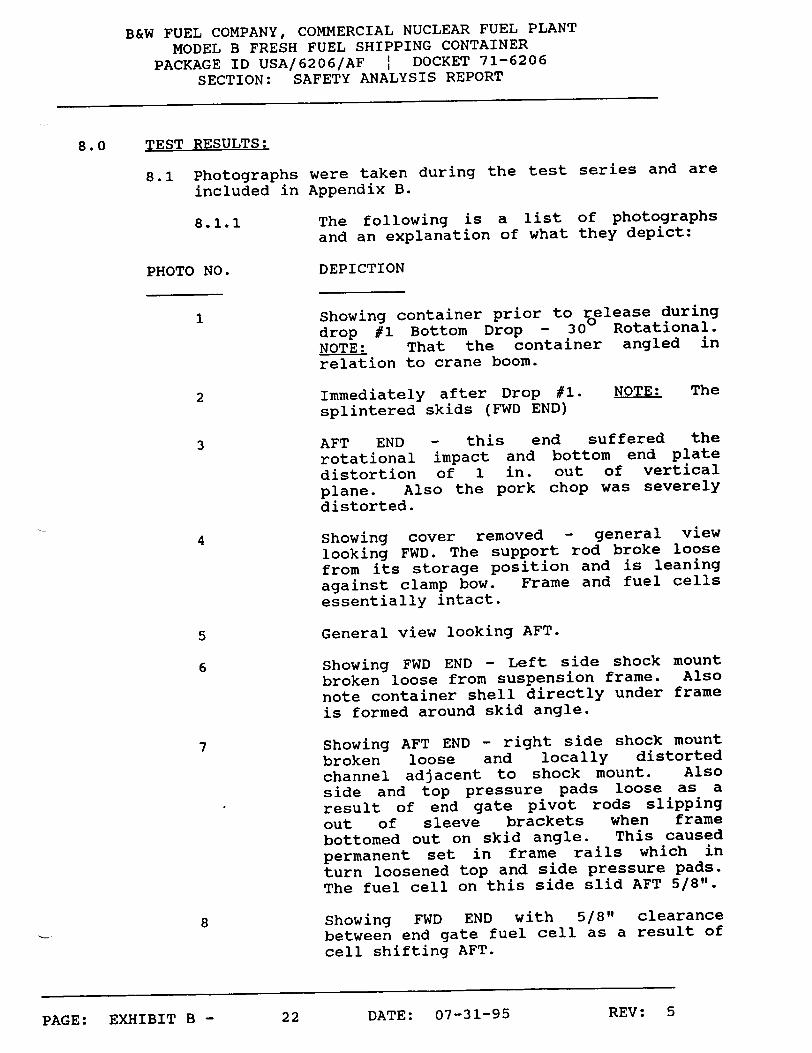
8.0 TEST RESULTS:
8.1 Photographs were taken during the test series and are
included in Appendix B.
8.1.1 The following is a list of photographs and an explanation of what they depict:
PHOTO NO. DEPICTION
1 Showing container prior to release during drop #1 Bottom Drop - 300 Rotational. NOTE: That the container angled in relation to crane boom.
2 Immediately after Drop #1. NOTE: The splintered skids (FWD END)
3 AFT END - this end suffered the
rotational impact and bottom end plate distortion of 1 in. out of vertical plane. Also the pork chop was severely distorted.
4 Showing cover removed - general view
looking FWD. The support rod broke loose from its storage position and is leaning against clamp bow. Frame and fuel cells essentially intact.
5 General view looking AFT.
6 Showing FWD END - Left side shock mount broken loose from suspension frame. Also note container shell directly under frame is formed around skid angle.
7 Showing AFT END - right side shock mount broken loose and locally distorted channel adjacent to shock mount. Also side and top pressure pads loose as a result of end gate pivot rods slipping out of sleeve brackets when frame bottomed out on skid angle. This caused permanent set in frame rails which in turn loosened top and side pressure pads. The fuel cell on this side slid AFT 5/8".
8 Showing FWD END with 5/8" clearance between end gate fuel cell as a result of cell shifting AFT.
REV: 522 DATE: 07-31-95PAGE: EXHIBIT B -

B&W FUEL COMPANY, COMMERCIAL NUCLEAR FUEL PLANT MODEL B FRESH FUEL SHIPPING CONTAINER
PACKAGE ID USA/6206/AF I DOCKET 71-6206 SECTION: SAFETY ANALYSIS REPORT
9 Showing local distortion of vertical poison plate caused by longitudinal bending (1/2" out of plane).
i0 Showing local distortion of frame alongside broken shear mount at AFT END.
ii Showing FWD END - bottom inside container - NOTE: skin formed over skid angle from frame bottoming out.
12 Showing AFT END view immediately after Drop #2.
13 Showing 3/4 view from AFT END.
14 Showing container in upright position after Drop #2.
15 Showing stacking bracket depressed and
tear in skin.
16 Showing container suspended above pin for Drop #3 40 in. PIN DROP TEST.
17 Same as #16 - opposite side.
18 Showing container on its side immediately after 40 in. PIN DROP. A 6 in. long cut through the skin resulted from the sharp edge of the dummy fuel cell inside the container striking the skin directly on the pin.
19 Showing container opened for examination after 40 in. PIN DROP. NOTE: The frame is still suspended by the shock mounts
with the exception of one mount at each end which broke from Drop #1. Close inspection reveals all of the clamp bows on the right side are bent as a result of impact from Drop #2 COVER DROP but still retain the fuel cells in a "NUCLEAR SAFE CONFIGURATION".
20 Showing view looking AFT (right side) NOTE: cracks in clamp bows where they
contact the pressure pads. Full force of
the impact from Drop #2 was taken by these members and although four were loose after the drop, the remaining five on this side were quite adequate to
. •VVUTUTM f -U 23 DATE: 07-31-95 REV: 5u•r1ftjr-

B&W FUEL COMPANY, COMMERCIAL NUCLEAR FUEL PLANT MODEL B FRESH FUEL SHIPPING CONTAINER
PACKAGE ID USA/6206/AF : DOCKET 71-6206 SECTION: SAFETY ANALYSIS REPORT
retain the fuel cell in its relative position to the other cell.
21 Showing view looking AFT - Left Side. NOTE: clamp bows and pressure pads undamaged but pressure pads at 3 stations were loose from frame distortion.
22 Showing close-up view of AFT END. NOTE: broken shock mount attachment to the frame and end gate pivot pins out of their sockets. Also note that clamp bow on near side is cracked and loose but clamp bow next to it is still tight and capable of restraining fuel cell.
23 Showing AFT END with fuel cell and end gate ass'y removed to expose "T" support casting which came through tests undamaged and maintained a "NUCLEAR SAFE CONFIGURATION" lateral spacing between cells of 2 11/16".
8.2 Measurements of container shell distortion disclosed
that the basic configuration of the base had been little affected by the drop tests and the maximum distortion resulted from the COVER DROP (Drop #2).
8.2.1 The ends of the cover received the full
force of the impact directly on the two
stacking brackets which were depressed to a greater degree than the cover shell itself. Actual measurement disclosed the cover shell had been uniformly depressed 3 inches throughout its length. (See Fig. I)
,, ORIGINAL SHELL F I CURVATURE
FIG I. 3" DEPRESSION
ENTIRE LENGTH
REV: 524 DATE: 07-31-95PAGE: EXHIBIT B -

B&W FUEL COMPANY, COMMERCIAL NUCLEAR FUEL PLANT
MODEL B FRESH FUEL SHIPPING CONTAINER PACKAGE ID USA/6206/AF I DOCKET 71-6206
SECTION: SAFETY ANALYSIS REPORT
8.2.2 At no time during the tests did the sealing flange hardware either break or even loosen. All were checked after each drop.
8.2.3 The photographs in APPENDIX B clearly show external areas of local container distortion which, considering the drop heights, were of minor consideration.
REV: 525 DATE: 07-31-95PAGE: EXHIBIT B -

B&W FUEL COMPANY, COMMERCIAL NUCLEAR FUEL PLANT
MODEL B FRESH FUEL SHIPPING CONTAINER
PACKAGE ID USA/6206/AF I DOCKET 71-6206 SECTION: SAFETY ANALYSIS REPORT
APPENDIX A to EXHIBIT B
TEST DIAGRAMS
REV: 526 DATE: 07-31-95PAGE: EXHIBIT B -

B&W FUEL COMPANY, COMMERCIAL NUCLEAR FUEL PLANT MODEL B FRESH FUEL SHIPPING CONTAINER
PACKAGE ID USA/6206/AF I DOCKET 71-6206
SECTION: SAFETY ANALYSIS REPORT
31 FT.
7/7 // /7/ ,/,/ ,/ ,/ /-D•D OPNAL
b1o' Ol~A T]•OP: - 3O° ?OTATIONAL'.
(
-C ."iW•R DROP - 3O0 ANGLE
27 DATE: 07-31-95PAGE: EXHIBIT B -
F/1 ./.7/7,/" /"
REV: 5

B&W FUEL COMPANY, COMMERCIAL NUCLEAR FUEL PLANT
MODEL B FRESH FUEL SHIPPING CONTAINER
PACKAGE ID USA/6206/AF I DOCKET 71-6206
SECTION: SAFETY ANALYSIS REPORT
50
cT. P .-V~o• To
D4Op
REV: 528 DATE: 07-31-95PAGE: EXHIBIT B -

B&W FUEL COMPANY, COMMERCIAL NUCLEAR FUEL PLANT
MODEL B FRESH FUEL SHIPPING CONTAINER
PACKAGE ID USA/6206/AF : DOCKET 71-6206
SECTION: SAFETY ANALYSIS REPORT
APPENDIX B to EXHIBIT B
TEST PHOTOGRAPHS
REV: 529 DATE: 07-31-95PAGE: EXHIBIT B -

B&W FUEL COMPANY, COMMERCIAL NUCLEAR FUEL PLANT
MODEL B FRESH FUEL SHIPPING CONTAINER
PACKAGE ID USA/6206/AF : DOCKET 71-6206
SECTION: SAFETY ANALYSIS REPORT
I
n A r•. 07-1q1-95 REV: 5-3 uPAGE: EXHIBIT B -

B&W FUEL COMPANY, COMMERCIAL NUCLEAR FUEL PLANT
MODEL B FRESH FUEL SHIPPING CONTAINER
PACKAGE ID USA/6206/AF I DOCKET 71-6206
SECTION: SAFETY ANALYSIS REPORT
.7
br
-' -- *-
I-% .
4-.
L
REV: 5PAGE: EXHIBIT B -
WW'i
-*w- ,
DATE: 07-31-9531

B&W FUEL COMPANY, COMMERCIAL NUCLEAR FUEL PLANT
MODEL B FRESH FUEL SHIPPING CONTAINER
PACKAGE ID USA/6206/AF I DOCKET 71-6206 SECTION: SAFETY ANALYSIS REPORT
a
OWjS~~
REV: 532 DATE: 07-31-95
I
PAGE: EXHIBIT B -

B&W FUEL COMPANY, COMMERCIAL NUCLEAR FUEL PLANT
MODEL B FRESH FUEL SHIPPING CONTAINER
PACKAGE ID USA/6206/AF I DOCKET 71-6206
SECTION: SAFETY ANALYSIS REPORT
REV: 533 DATE: 07-31-95PAGE: EXHIBIT B -

B&W FUEL COMPANY, COMMERCIAL NUCLEAR FUEL PLANT
MODEL B FRESH FUEL SHIPPING CONTAINER
PACKAGE ID USA/6206/AF I DOCKET 71-6206
SECTION: SAFETY ANALYSIS REPORT
7ra
REV: 534 DATE: 07-31-95PAGE: EXHIBIT B -

B&W FUEL COMPANY, COMMERCIAL NUCLEAR FUEL PLANT
MODEL B FRESH FUEL SHIPPING CONTAINER
PACKAGE ID USA/6206/AF I DOCKET 71-6206
SECTION: SAFETY ANALYSIS REPORT
I0
REV: 5PAGE: EXHIBIT B - DATE: 07-31-9535

B&W FUEL COMPANY, COMMERCIAL NUCLEAR FUEL PLANT
MODEL B FRESH FUEL SHIPPING CONTAINER
PACKAGE ID USA/6206/AF I DOCKET 71-6206
SECTION: SAFETY ANALYSIS REPORT
I
14Di op*Z (INVERTEO)
REV: 536 DATE: 07-31-95
'3
Is
PAGE: EXHIBIT B -

B&W FUEL COMPANY, COMMERCIAL NUCLEAR FUEL PLANT
MODEL B FRESH FUEL SHIPPING CONTAINER
PACKAGE ID USA/6206/AF I DOCKET 71-6206
SECTION: SAFETY ANALYSIS REPORT
lb
17
Is
DRoP*3 (p plIN DROP)
REV: 537 DATE: 07-31-95PAGE: EXHIBIT B -

B&W FUEL COMPANY, COMMERCIAL NUCLEAR FUEL PLANT
MODEL B FRESH FUEL SHIPPING CONTAINER
PACKAGE ID USA/6206/AF I DOCKET 71-6206
SECTION: SAFETY ANALYSIS REPORT
19
- to
38 DATE: 07-31-95 REV: 5PAGE: EXHIBIT B -

B&W FUEL COMPANY, COMMERCIAL NUCLEAR FUEL PLANT
MODEL B FRESH FUEL SHIPPING CONTAINER
PACKAGE ID USA/6206/AF I DOCKET 71-6206
SECTION: SAFETY ANALYSIS REPORT
22
23
D0fATE: 07-31-95 REV:5PAGE: EXA1±D11 B -

B&W FUEL COMPANY, COMMERCIAL NUCLEAR FUEL PLANT
MODEL B FRESH FUEL SHIPPING CONTAINER
PACKAGE ID USA/6206/AF I DOCKET 71-6206
SECTION: SAFETY ANALYSIS REPORT
EXHIBIT C
LIFT AND TIE DOWN PROVISIONS
ON MODEL B FRESH FUEL SHIPPING CONTAINER
REV: 51 DATE: 07-31-95PAGE: EXHIBIT C -

B&W FUEL COMPANY, COMMERCIAL NUCLEAR FUEL PLANT
MODEL B FRESH FUEL SHIPPING CONTAINER
PACKAGE ID USA/6206/AF I DOCKET 71-6206
SECTION: SAFETY ANALYSIS REPORT
EXHIBIT C
TABLE OF CONTENTS
PAGE
I) Requirements
Geometry of Attachment Points on the Container
III) Forces Acting on the Container
Stress Analysis of Attachment
Modes of Failure
C-3
C-4
C-10 C-15
C-27
PAGE: EXHIBIT C -n. A n•p 07-31-95 REV: 5
II)
IV)
V)
4

B&W FUEL COMPANY, COMMERCIAL NUCLEAR FUEL PLANT
MODEL B FRESH FUEL SHIPPING CONTAINER
PACKAGE ID USA/6206/AF I DOCKET 71-6206
SECTION: SAFETY ANALYSIS REPORT
I) REQUIREMENTS
It is the purpose of this report to show the
compliance of the handling and transportation
provisions with the NRC Specification Part 71
Packaging of Radioactive Material for Transport,
Subpart C - Package Standards, Par. 71.31.
3 DATE: 07-31-95PAGE: EXHIBIT C -
REV: 5

B&W FUEL COMPANY, COMMERCIAL NUCLEAR FUEL PLANT
MODEL B FRESH FUEL SHIPPING CONTAINER
PACKAGE ID USA/6206/AF I DOCKET 71-6206
SECTION: SAFETY ANALYSIS REPORT
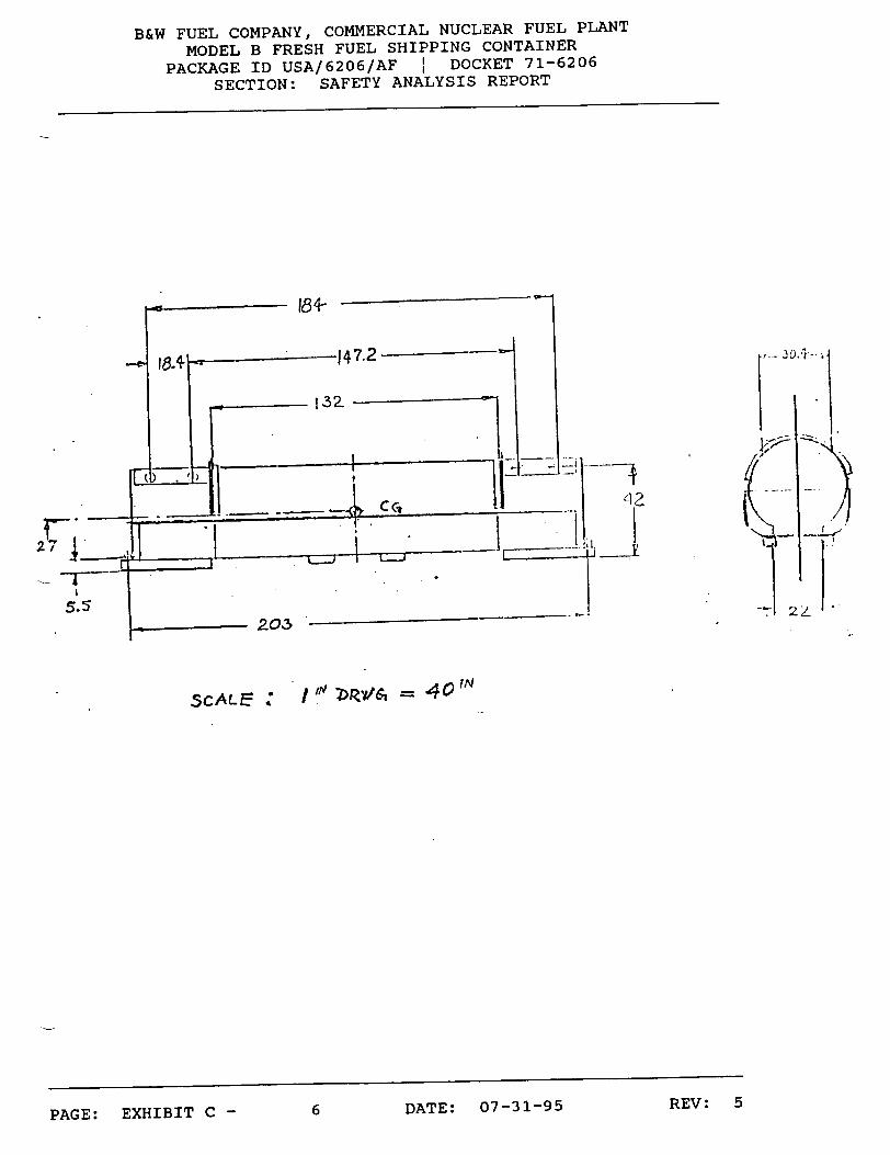
II) GEOMETRY OF ATTACHMENT POINTS ON THE CONTAINER
REV: 5PAGE: EXHIBIT C - DATE: 07-31-954

B&W FUEL COMPANY, COMMERCIAL NUCLEAR FUEL PLANT
MODEL B FRESH FUEL SHIPPING CONTAINER
PACKAGE ID USA/6206/AF : DOCKET 71-6206
SECTION: SAFETY ANALYSIS REPORT
INTE.PLOCKjfCf , 3 L7s
4.+ LIFT
HOLE5
TOWIN'a HOLM-S
PAGE: EXHIBIT C -.... rp v w n7-31-95 REV: 5
a
B&W FUEL COMPANY, COMMERCIAL NUCLEAR FUEL PLANT
MODEL B FRESH FUEL SHIPPING CONTAINER
PACKAGE ID USA/6206/AF I DOCKET 71-6206
SECTION: SAFETY ANALYSIS REPORT
42
-i
ScALE :
REV: 56 DATE: 07-31-95
27 4
I 'N 'Z>Rv/$ = 40 10
PAGE: EXHIBIT C -

B&W FUEL COMPANY, COMMERCIAL NUCLEAR FUEL PLANT
MODEL B FRESH FUEL SHIPPING CONTAINER
PACKAGE ID USA/6206/AF I DOCKET 71-6206
SECTION: SAFETY ANALYSIS REPORT
AkJGLL -5;,D Z~x 3k
SKIN •&9 TUCK<
;-HCK.
F(ILL 27-WF-LD3 (6 zcs
0 > "I,,
(2PLCs)
ROLLOVc•R ANGLE 2.x2x'
BACK-UP PLATS •-7f-TK,
FILLET ý/EL~D 31, ALL APuN'W'
32
FILLF-T WELU
(2iPL C s)
"TILIL5.-.r VLD SxWIýL2
T6. _L7- 3.Z (2 PL-cs ow 7o70 )
REV: 57 DATE: 07-31-95
FI ._ -3
PAGE: EXHIBIT C -

B&W FUEL COMPANY, COMMERCIAL NUCLEAR FUEL PLANT
MODEL B FRESH FUEL SHIPPING CONTAINER
PACKAGE ID USA/6206/AF DOCKET 71-6206
SECTION: SAFETY ANALYSIS REPORT
LcAZON;= /_/ -1 A •),"- . 0.*v
fyit
rIG .L -S,1
4.
REV: 58 DATE: 07-31-95
TTr
30
?T
PAGE: EXHIBIT C -
B&W FUEL COMPANY, COMMERCIAL NUCLEAR FUEL PLANT MODEL B FRESH FUEL SHIPPING CONTAINER
PACKAGE ID USA/6206/AF I DOCKET 71-6206 SECTION: SAFETY ANALYSIS REPORT
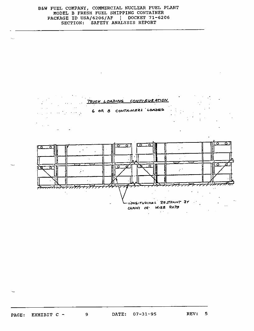
7t, ¢C LOAZ/---*NG crQt UmRT'CAl
.. OR a CowIrAiNAR •;I-OwJ
-*Low&i'FINAS L 09-WI RAPT ."•? ,
9 DATE: 07-31-95 REV: 5PAGE: EXHIBIT C -
B&W FUEL COMPANY, COMMERCIAL NUCLEAR FUEL PLANT
MODEL B FRESH FUEL SHIPPING CONTAINER PACKAGE ID USA/6206/AF 1 DOCKET 71-6206
SECTION: SAFETY ANALYSIS REPORT
III) FORCES ACTING ON THE CONTAINER
1) Lifting forces per requirements on I - 2 acting on the
lift eyes.
2) Tie down forces under scheduled loading conditions.
3) Tie down forces - unscheduled, but possible through
use of lift eyes for tie down. Worst condition.
REV: 510 DATE: 07-31-95PAGE: EXHIBIT C -

B&W FUEL COMPANY, COMMERCIAL NUCLEAR FUEL PLANT
MODEL B FRESH FUEL SHIPPING CONTAINER
PACKAGE ID USA/6206/AF I DOCKET 71-6206
SECTION: SAFETY ANALYSIS REPORT
- L 1�F1MC<�O�C�BS AT 36 .�POCA•
* I L L
FL. -L~ 2J1,500 LS
LIFTItNG Fo.c
L L.21, 900 LBS
FL
,S.CL ý.. )-0,00 U.OLaS
REV: 5
11 DATE: 07-31-95
"•e.,v --- "•J;<Co.: ZO.
21300 4<- 0,e4
REV: 5PAGE: EXHIBIT C -

B&W FUEL COMPANY, COMMERCIAL NUCLEAR FUEL PLANT
MODEL B FRESH FUEL SHIPPING CONTAINER
PACKAGE ID USA/6206/AF I DOCKET 71-6206
SECTION: SAFETY ANALYSIS REPORT
LiFBN, G OpC- AT 3G..SHOCK D•.Tz~~pH•MI ~-? .-. N..A. -. ,--. -- L_
oF cr--.. - LiFF
LUG
---. --- 0 LL S
rc�
I .
VECTO- 6 V0 LL -- I"" LLS
REV: 512 DATE: 07-31-95
Csommm7T4 AT(2-ANGF-FT
c• .A .r -
T-t T I \ -e
SCALA; p i n1 0 1 [ O, O 0 t,- !'
PAGE: EXHIBIT C -

B&W FUEL COMPANY, COMMERCIAL NUCLEAR FUEL PLANT
MODEL B FRESH FUEL SHIPPING CONTAINER
PACKAGE ID USA/6206/AF I DOCKET 71-6206
SECTION: SAFETY ANALYSIS REPORT
"11E D)OWN FORCES AT IMPACT
LONG)-. PL^A1'
C;40-K, NOT ?R0VQ:.D-SD
ACcr&3 AND SFACE. foe. SOLID
ALf.WA4t %6. /4IA/LA
AS Ar •oV+ r:to$
COCKINC', kAY NOT
|H PACT VECTfOR.--
I1'iPACT 1FO- C- V7C.o•
1N, Lr4lwIT, .PLAq=-
/
/
_'I"=-- 'DOVN r-0-C£E. VECT01Z LoNGIITuD. PLANE= - 45'0
4. 2 5-00 L'B,!o
VL. - lOOx i0.2 , '... 50u L2
CNIDEF- ANGLE .c& II2"
/
,5CALE! If= 2 0, 00 0_L•%
REV: 513 DATE: 07-31-95PAGE: EXHIBIT C -

B&W FUEL COMPANY, COMMERCIAL NUCLEAR FUEL PLANT
MODEL B FRESH FUEL SHIPPING CONTAINER
PACKAGE ID USA/6206/AF I DOCKET 71-6206
SECTION: SAFETY ANALYSIS REPORT
TIE. DOWN For~C• % AT it-PAc-r-1 IJ-2 V/L$_ Pk -•k,.
,LON -H ...S</DE _
,lIPACr VECTORS
.JMPA~r FORCE 1V2Tcmi
UNIDE.. ANaLEF_ (s- 21.so .
rn DOWN .-i--C..7 .A ,C'7 O 5"F, "S.t~r"-- W'..s ?L.•ANS =I•1•
4�Lrr 7oi�qr
]�)(4� .±X: Vi X
, -0= - 2!00 L.5
REV: 514 DATE: 07-31-95
.. C . ?rcovIE.D
?1 =o0mrf ; - A- 0
PAGE: EXHIBIT C -
B&W FUEL COMPANY, COMMERCIAL NUCLEAR FUEL PLANT
MODEL B FRESH FUEL SHIPPING CONTAINER PACKAGE ID USA/6206/AF I DOCKET 71-6206
SECTION: SAFETY ANALYSIS REPORT
IV) STRESS ANALYSIS OF ATTACHMENT POINTS
1) Towing Eyes
Used as a guide for longitudinal restraint under about 45
degree angle downwards.
The portion as part of the base frame with skids and
stressed in the outlined direction is obviously very bulky
and rigid that there is no need for a detailed
investigation on strength.
2) Lifting Eyes
The lifting force per lug of F = 11,000 lbs (III -3) is
less strain to tear out the hofe than the unscheduled tie
down Force Rt = 30,632 lbs.
-.... .. y..... nh!Pr- 07-11-Q5 REV: 5PAGE: rýAn1DJ-±K %~- -

B&W FUEL COMPANY, COMMERCIAL NUCLEAR FUEL PLANT
MODEL B FRESH FUEL SHIPPING CONTAINER
PACKAGE ID USA/6206/AF I DOCKET 71-6206
SECTION: SAFETY ANALYSIS REPORT
MA;iMU, Tlj •o., . o
* ~ X- 0,.j.• -
VEcTor. • 2.350 LR,
~U~LT~rRr
3 V0,-3463zL
V~craf-. bc=
q
R ..E-- tl-A k,1 "F r- .-DOW N eERT
REV: 516 DATE: 07-31-95PAGE: EXHIBIT C -

B&W FUEL COMPANY, COMMERCIAL NUCLEAR FUEL PLANT
MODEL B FRESH FUEL SHIPPING CONTAINER PACKAGE ID USA/6206/AF : DOCKET 71-6206
SECTION: SAFETY ANALYSIS REPORT
.....-F .% OM1 LJT ,•7- E-. ._TE. " IC,. -TO TEA?, our OuLE
"., .~C o•'• , 7•-C& -yCAN GLLA70 Ht
.. b. IP.L•L-NG? IN 'PLA.M7= .0;-- HOL. ..
*.c•--- 2,&5 2L1'35
_ = : 2. L 's 30so _
REV: 517 DATE: 07-31-95PAGE: EXHIBIT C -

B&W FUEL COMPANY, COMMERCIAL NUCLEAR FUEL PLANT
MODEL B FRESH FUEL SHIPPING CONTAINER
PACKAGE ID USA/6206/AF : DOCKET 71-6206
SECTION: SAFETY ANALYSIS REPORT
LOC.ATIONJ OF A T*1 o HO4)( 'N "
LDFTtING jYVJ
-K
2b
.,SECTION A-A
REV: 5PAGE: EXHIBIT C -
TENDEWCY S'He*k
DATE: 07-31-9518

B&W FUEL COMPANY, COMMERCIAL NUCLEAR FUEL PLANT
MODEL B FRESH FUEL SHIPPING CONTAINER
PACKAGE ID USA/6206/AF : DOCKET 71-6206 SECTION: SAFETY ANALYSIS REPORT
2.1 Vector "a" Pulling Rectanqular to the Lift Hole
The hook will be located somewhat higher than at the
45 degree axis because of diminishing space behind the
backup plate.
Actual conditions do not allow a standard calculation
procedure. We adapt the dimensions to the case #60 of
Formulas for Flat Plates, Table X, Page 232, in
"Roark, Formulas for Stress and Strain, ,, McGraw-Hill
Book Company.
REV: 519 DATE: 07-31-95PAGE: EXHIBIT C -

B&W FUEL COMPANY, COMMERCIAL NUCLEAR FUEL PLANT
MODEL B FRESH FUEL SHIPPING CONTAINER
PACKAGE ID USA/6206/AF I DOCKET 71-6206
SECTION: SAFETY ANALYSIS REPORT
ACWUAL COtNINYTONJ
AREA 0=
166
3VA " ".
3 7 "T" .lCK.~l•
S-G .:Z°-
1-
,_hl'1ULA'hFL• ) CONDI-ION
CRCULAR ý>LArE V/iTN CoILm-r- TiL.
1. HOLE . I'DIA "
VEDTO• Q -
3%
REV: 520 DATE: 07-31-95PAGE: EXHIBIT C -
\
ý 7 YX V1 6

B&W FUEL COMPANY, COMMERCIAL NUCLEAR FUEL PLANT
MODEL B FRESH FUEL SHIPPING CONTAINER
PACKAGE ID USA/6206/AF I DOCKET 71-6206
SECTION: SAFETY ANALYSIS REPORT
r. rnCircular Plate With Concentric Hole Outer Edge Fixed Inner Edge Free
Uniform load on concentric circular ring of Radius rO.
Our application shows only a local area where the hook
touches the back-up plate. To about conform with the
conditions of the formula, we multiply the force with 1.3.
Max. stress at inner edge:
St = 3 w 4 mt 2 (m + 1)(2 loge a + r 0 2
ro 2 a
2 I 2 -a (6m_ - 1) - b- (m + 1)
t a (m- 1) + (m + )
Factor M:
M - W (m - 1) + 2 ( 2 loge a + r 0 2 -2
8 m r0 a
W = Total applied load = 1.3 x Vector "x" = 1.3 x 2350 =
- 3700 lbs.
m = Reciprocal of (Poisson's Ratio ) = 1 0.27 = 3.7
t = Thickness of plate = 0.44 in.
a = outside radius = 2.5 in.
b = inside radius = 1.5 in.
21 DATE: 07-31-95PAGE: EXHIBIT C -
REV: 5REV: 5

B&W FUEL COMPANY, COMMERCIAL NUCLEAR FUEL PLANT MODEL B FRESH FUEL SHIPPING CONTAINER
PACKAGE ID USA/6206/AF I DOCKET 71-6206 SECTION: SAFETY ANALYSIS REPORT
r = radius of location of applied force = 2 in.
St = 3 x 3.700 2 4 x 3.7 (0.44)
(3.7 + 1)(2 loge 2.5 + 22 - 1) 2.0 5
114.3 2.52 (3.7 - 1) - 1.52 . (0.44)- 2.5 (3.7 - 1) + 1.5 (3.7 + 1)
= -1233.7 4.7 x 0.86 - 3542 16.875 - 10.575 16.875 + 10.575
= -498.7 - 812.9 = -1,311.5 PSI
M = 3700 8 x 3.7
= 39.8 2.7 + 0.172
(3.7 - 1) + 2 (2 loge 2.5 + 222 - 1) 2.0 2.5
= 114.3
2.2 VECTOR "b" PULLING IN PLANE OF HOLE
According to the sketch, the tendency to shear occurs at two weak points with the following area:
A = (1.6 + 0.7) x 0.44 = 1.02 in2
Stress S = V2• 2
A30,500= 29,900 PSI
1.02
Ssyield
3. WELDING OF THE STACKING BRACKET
The fillet welds are located in two planes on the container shell. Each plane is analyzed separately. The connection welds to the rollover ring are placed in the same level as the other in order to simplify the calculation.
Here again the analysis of the forces applied shows that the tie down force Rt is the worst stress condition on the
s t structural connection.
22 DATE: 07-31-95PAGE: EXHIBIT C - REV: 5

B&W FUEL COMPANY, COMMERCIAL NUCLEAR FUEL PLANT MODEL B FRESH FUEL SHIPPING CONTAINER
PACKAGE ID USA/6206/AF I DOCKET 71-6206 SECTION: SAFETY ANALYSIS REPORT
WELD PATTERN
LOCATION OF THE TWO PLANES
SIEw y
23 DATE: 07-31-95
Ornif >< - ..
PAGE: EXHIBIT C - REV: 5

B&W FUEL COMPANY, COMMERCIAL NUCLEAR FUEL PLANT MODEL B FRESH FUEL SHIPPING CONTAINER
PACKAGE ID USA/6206/AF 1 DOCKET 71-6206 SECTION: SAFETY ANALYSIS REPORT
LIFTING FORCES ON WELDS
SCALE 1" 2000 lbs
Fcv/2 = 2915 lbs. Pis = 2600 lbs. PIT = 1000 lbs. FL/ 4 = 5038 lbs. PIL = 4400 lbs.
I'll. -
ViWy.
PlL = 4400 lbs. P2T = 2250 lbs. P2S = 1900 lbs.
24 DATE: 07-31-95
44d,�
. . I
REV: 5PAGE: EXHIBIT C -

B&W FUEL COMPANY, COMMERCIAL NUCLEAR FUEL PLANT
MODEL B FRESH FUEL SHIPPING CONTAINER PACKAGE ID USA/6206/AF I DOCKET 71-6206
SECTION: SAFETY ANALYSIS REPORT
WELDS - TIE
SCALE is,
DOWN FORCES
2000 lbs
VIPEW,
' . /.
// S./ .
. /.
REV: 525 DATE: 07-31-95
VIEl
WELDS - TIE
A, .,or -4114 ri
I
PAGE: EXHIBIT C -

B&W FUEL COMPANY, COMMERCIAL NUCLEAR FUEL PLANT MODEL B FRESH FUEL SHIPPING CONTAINER
PACKAGE ID USA/6206/AF I DOCKET 71-6206 SECTION: SAFETY ANALYSIS REPORT
WELDS - TIE DOWN FORCES
SCALE 1" 2000 lbs
FS2/4 = 5470 lbs. FVL/ 4 = 15200 lbs.
P3S = 10000 lbs. P = 10700 lbs. P3R = 4400 lbs.
?3s
y
REV: 526 DATE: 07-31-95
I
PAGE: EXHIBIT C -
B&W FUEL COMPANY, COMMERCIAL NUCLEAR FUEL PLANT MODEL B FRESH FUEL SHIPPING CONTAINER
PACKAGE ID USA/6206/AF I DOCKET 71-6206 SECTION: SAFETY ANALYSIS REPORT
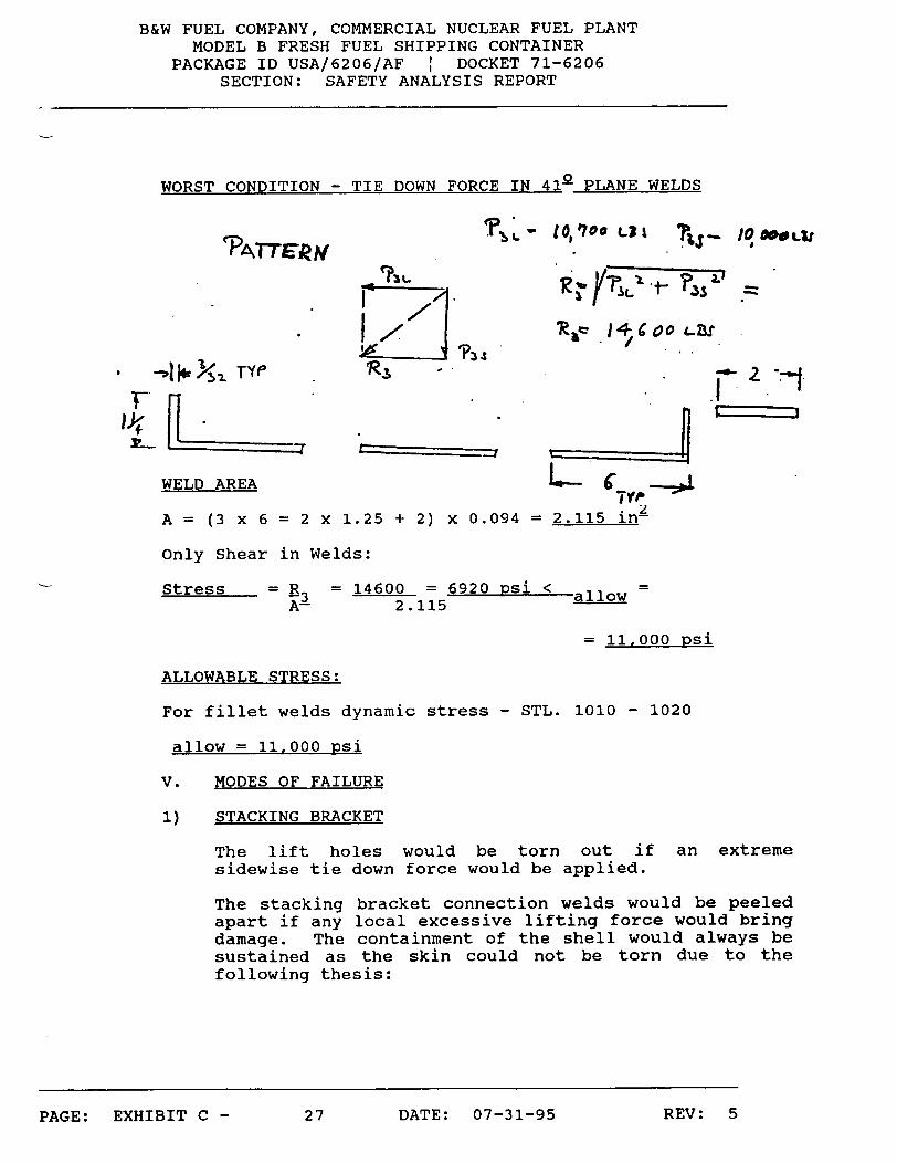
WORST CONDITION - TIE DOWN FORCE IN 412 PLANE WELDS
WEALTTERE
WELD AREA
F1- 10,1'00 L71
4 Coo I--S
.1 '-.
'====== .rEL
A = (3 x 6 = 2 x 1.25 + 2) x 0.094 = 2.115 in2
Only Shear in Welds:
Stress R = 14600 = 6920 psi < allow AP 2.115alo
= 11,000 psi
ALLOWABLE STRESS:
For fillet welds dynamic stress - STL. 1010 - 1020
allow = 11.000 Dsi
V. MODES OF FAILURE
1) STACKING BRACKET
The lift holes would be torn out if an sidewise tie down force would be applied.
extreme
The stacking bracket connection welds would be peeled apart if any local excessive lifting force would bring damage. The containment of the shell would always be sustained as the skin could not be torn due to the following thesis:
27 DATE: 07-31-95
-Io WeL,
PAGE: EXHIBIT C - REV: 5

B&W FUEL COMPANY, COMMERCIAL NUCLEAR FUEL PLANT
MODEL B FRESH FUEL SHIPPING CONTAINER
PACKAGE ID USA/6206/AF I DOCKET 71-6206
SECTION: SAFETY ANALYSIS REPORT
13/3k.
W ELL D
S4k1 MR.ACMRk.E
The cross-sectional area of the skin is about twice
the weld area.
Ratio As = Aw
12.5 x 0.089 6 x 0.094
2) TOWING PROVISIONS
The positioning of the tie down force near the towing
hole would mean that during excessive shock the tie
down chains or ropes fail. This is obvious, as the
container base plus lower shell and hardwood skid and
rollover braces are connected to a very rigid
structure.
REV: 528 DATE: 07-31-95PAGE: EXHIBIT C -
- 1.97 1 = 2:1