Embed Size (px)
Citation preview

EXHIBIT A
OVERVIEW –IMPACTS OF MID-LEVEL ETHANOL ON-ROAD AND NON-ROAD ENGINES AND EQUIPMENT (PREPARED BY DR. RON SAHU, MAY 15, 2009)
A. Change Due to the Enleanment Effect of Ethanol
Gasoline is a mixture of many hydrocarbon compounds that consist mainly of hydrogen
and carbon.1 Ethanol also contains hydrogen and carbon – but, in addition, it also contains
oxygen. The exact air-to-fuel ratio needed for complete combustion of the fuel (to carbon
dioxide and water vapor) is called the "stoichiometric air-to-fuel ratio." This ratio is about 14.7 to
1.0 (on weight basis) for gasoline. For ethanol/gasoline blends less air is required for complete
combustion because oxygen is contained in the ethanol and because some of the hydrocarbons
have been displaced. For example, for E10 the stoichiometric air-to-fuel ratio is 14.0 to 14.1
pounds of air per pound of fuel. Indeed, the stoichiometric air-to-fuel ratio for straight ethanol is
9 to 1 so that as the proportion of ethanol in the gasoline blend increases so must the air-to-fuel
ratio decrease. To deliver the required power for any given operating condition, engines
consume enough air and fuel to generate the energy required, to the limit of the engine’s
capabilities. Because fuel delivery systems are designed to deliver the prescribed amount of fuel
on a volume control basis the fuel volume delivered is related to the volume of air introduced.
The engine design anticipates that the fuel utilized will match the air-to-fuel ratio characteristics
utilized in the engine design and calibration. Because ethanol blended fuels require more fuel for
the same amount of air to achieve stoichiometric conditions, the fuel system must adapt by
introducing more fuel or the desired mixture is not achieved. If additional fuel is not introduced
to compensate for the ethanol the resulting mixture has less fuel than desired; the effect of this
type of fuel change on an engine is called “enleanment.”
1 Sulfur, nitrogen, and trace elements also may be present.
2
Even with closed-loop systems, where the engine has a control system that can detect and
compensate for the effects of ethanol addition (adapt), if the fuel contains an amount of ethanol
that is outside the range of the system design, the engine similarly may receive too much oxygen
and operate in a lean condition. Lean operation can lead to a variety of performance problems,
for example the combustion and exhaust gas temperatures will be higher, engine starting may
become more difficult, and the engine speed control may become inaccurate.2 These problems
may result in the unintentional engagement of cutting chains and blades on chainsaws and other
products – because the engines driving these products will run at higher speeds, especially at idle
conditions.
The increased combustion and exhaust gas temperatures resulting from lean operation
can result in severe damages to pistons, gaskets, catalysts and emissions-related components, in
turn, resulting in the failure of the product to operate and increased exhaust emissions.3 These
increased temperatures can also damage and destroy critical safety components like spark
arrestors – as required by the U.S. Forest Service to be used on chainsaws to reduce fire risks.
B. Effect on Exhaust Emissions
Enleanment and the increased heat from mid-level ethanol blends will cause heat-related
damage to the engine over its useful life, which can cause dramatic increases in hydrocarbon
emissions. NOx emissions from conventional products and vehicles generally increase
2 Issues associated with driveability and operational problems have been discussed for on-
road vehicles and for off-road equipment in a series of reports in 2002-2004 by Orbital Engine Company for a biofuels assessment conducted in Australia. In particular, see (a) A Testing Based Assessment to Determine Impacts of a 10% and 20% Ethanol Gasoline Fuel Blend on Non-Automotive Engines, January 2003; (b) Marine Outboard Driveability Assessment to Determine Impacts of a 10% and 20% Ethanol Gasoline Fuel Blend on a Small Batch of Engines, February 2003 and (c) A Testing Based Assessment to Determine Impacts of a 20% Ethanol Gasoline Fuel Blend on the Australian Passenger Vehicle Fleet – 2000hrs Material Compatibility Testing, May 2003.
3 Id.
3
immediately since enleanment creates conditions which increase NOx.4 For less sophisticated
open-loop engines, NOx emission increases can be dramatic.
While some of the toxics in exhaust emissions show expected decreases in the presence
of ethanol, some toxics, such as aldehydes, can show increases. Besides the potential toxic
effects of aldehydes in exhaust gases, the aldehydes act as an ozone precursor and increase the
smog-forming potential.
C. Effect on Water Solubility and Phase Separation
Separation of a single phase gasoline into a "gasoline phase" and a "water phase" can
occur when too much water is introduced into the fuel tank. Water contamination is most
commonly caused by improper fuel storage practices at the fuel distribution or retail level, or the
accidental introduction of water during vehicle refueling. Water has a higher density than
gasoline, so if water separates, it will form a layer below the gasoline. Because most engines
obtain their fuel from, or near, the bottom of the fuel tank, engines will not run if the fuel pick up
is in the water-phase layer.
Typically, gasoline can absorb only very small amounts of water before phase separation
occurs. Ethanol/gasoline blends, due to ethanol's greater affinity with water, can absorb
significantly more water without phase separation occurring than gasoline. Ethanol blends can
actually dry out tanks by absorbing the water and allowing it to be drawn harmlessly into the
engine with the gasoline. If, however, too much water is introduced into an ethanol blend, the
water and most of the ethanol will separate from the gasoline and the remaining ethanol. The
amount of water that can be absorbed by ethanol/gasoline blends, without phase separation,
varies from 0.3 to 0.5 volume percent, depending on temperature, aromatics, and ethanol content.
4 The higher combustion temperatures and the excess of oxygen in the combustion
chamber result in the excess oxygen combining with nitrogen to produce nitrogen oxides.
4
If phase separation were to occur, the ethanol/water mixture would be drawn into the engine and
the engine would most likely stop.
In some situations, ethanol/gasoline blends might absorb water vapor from the
atmosphere, leading to phase separation. Such problems are of greater concern for engines with
open-vented fuel tanks that are operated in humid environments, such as marine engines.
Additionally, more complex phenomena such as lubricating oil/fuel separation (in 2-
stroke engines) and temperature-induced phase separation of various fuel components have also
been noted.
D. Effect on Material Compatibility
A variety of components in engine/equipment systems can come into contact with the
fuel. These include
• Fuel Lines
• Fuel Tanks
• Fuel Pumps
• Fuel Injectors
• Fuel Rails
• Carburetors (and internal components)
• Pressure Regulators
• Valves
• O-Rings
• Gaskets
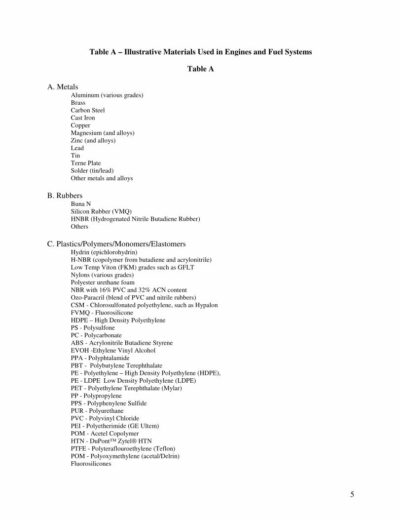
Materials used in these components should be compatible with the full range of expected
fuel composition. Table A shows the types of metals, rubbers, and plastics that are used in
existing engines and fuel system components currently designed to run on E10 fuel blends.
5
Table A – Illustrative Materials Used in Engines and Fuel Systems
Table A
A. Metals Aluminum (various grades)
Brass
Carbon Steel
Cast Iron
Copper
Magnesium (and alloys)
Zinc (and alloys)
Lead
Tin
Terne Plate
Solder (tin/lead)
Other metals and alloys
B. Rubbers Buna N
Silicon Rubber (VMQ)
HNBR (Hydrogenated Nitrile Butadiene Rubber)
Others
C. Plastics/Polymers/Monomers/Elastomers Hydrin (epichlorohydrin)
H-NBR (copolymer from butadiene and acrylonitrile)
Low Temp Viton (FKM) grades such as GFLT
Nylons (various grades)
Polyester urethane foam
NBR with 16% PVC and 32% ACN content
Ozo-Paracril (blend of PVC and nitrile rubbers)
CSM - Chlorosulfonated polyethylene, such as Hypalon
FVMQ - Fluorosilicone
HDPE – High Density Polyethylene
PS - Polysulfone
PC - Polycarbonate
ABS - Acrylonitrile Butadiene Styrene
EVOH -Ethylene Vinyl Alcohol
PPA - Polyphtalamide
PBT - Polybutylene Terephthalate
PE - Polyethylene – High Density Polyethylene (HDPE),
PE - LDPE Low Density Polyethylene (LDPE)
PET - Polyethylene Terephthalate (Mylar)
PP - Polypropylene
PPS - Polyphenylene Sulfide
PUR - Polyurethane
PVC - Polyvinyl Chloride
PEI - Polyetherimide (GE Ultem)
POM - Acetel Copolymer
HTN - DuPont™ Zytel® HTN
PTFE - Polyteraflouroethylene (Teflon)
POM - Polyoxymethylene (acetal/Delrin)
Fluorosilicones
6
Others
This is not an exhaustive list and is meant as an illustration of the diversity of materials
used presently. Based on existing studies, it is clear that several rubbers and elastomers can
swell and deteriorate more rapidly in the presence of ethanol.5 Ethanol also corrodes certain
metals. Corrosion occurs through different mechanisms including acidic attack, galvanic
activity, and chemical interaction. The first is caused by water in the fuel. Ethanol attracts and
dissolves water, creating a slightly acidic solution. Unlike gasoline, ethanol alone or combined
with water conducts electricity; this conductivity creates a galvanic cell that causes exposed
metals to corrode. So when ethanol is blended with gasoline the resulting blend is conductive
and the conductivity increases as the amount of ethanol is increased. The addition of ethanol
greatly increases the ability of gasoline to dissolve ionic impurities which can facilitate corrosive
attach of many metals. Another mechanism is direct chemical interaction with ethanol molecules
on certain metals.
Clearly, deterioration of materials would result in loss of function of critical engine
components, resulting in fuel leaks, fires from fuel leaks, and equipment failure. This has
obvious safety implications.
E. Effect on Evaporative Emissions
Permeation of fuel through elastomers can result in deterioration of these materials. In
recent testing, all of the tested ethanol blends showed higher permeation rates through elastomers
5 A Testing Based Assessment to Determine Impacts of a 20% Ethanol Gasoline Fuel
Blend on the Australian Passenger Vehicle Fleet – 2000hrs Material Compatibility Testing, May 2003 and A Testing Based Assessment to Determine Impacts of a 10% and 20% Ethanol Gasoline Fuel Blend on Non-Automotive Engines - 2000hrs Material Compatibility Testing, May 2003.
7
than conventional gasoline.6 An important emissions concern that remains poorly understood is
ethanol’s ability to permeate through rubber, plastic, and other materials used widely in the fuel
tank, fuel system hoses, seals, and other parts of the fuel handling system. Recent studies have
shown these emissions can be quite significant.7
F. Impacts Associated with Fuel Volatility
Mid-level ethanol gasoline blends are documented as causing the following operating
problems resulting from their different volatility and vaporization characteristics. First, because
ethanol has a lower vapor pressure, it has been shown to cause starting problems because there is
inadequate vapor pressure to a vapor mixture rich enough to ignite. In turn, such problems could
result in consumer tampering of the engine’s carburetor.
Second, because ethanol vaporizes at lower temperatures than gasoline, mid-level ethanol
can cause “vapor lock.” Vapor lock is a condition where the fuel in the engine’s fuel delivery
system vaporizes preventing the transport of liquid fuel to the carburetor or fuel injectors.
Increasing the ethanol concentration beyond E10 is likely to increase the likelihood of vapor lock
for open loop fuel control system engines typically used on older vehicles and most off-road
engines. Even in the closed loop engine systems used in some off-road engines and in most late-
model vehicles, there remains the likelihood of vapor lock.
Other concerns about low temperature fuel characteristics of ethanol blends include a)
increased viscosity of ethanol/gasoline blends which may impede fuel flow and b) phase
separation in the vehicle fuel system due to reduced water solubility.
6 (a) See EPA-420-D-06-004, Draft Regulatory Impact Analysis: Control of Hazardous Air
Pollutants from Mobile Sources, Chapter 7, February 2006. (b) See also, Fuel Permeation from Automotive Systems: E0, E6, E10, E20, and E85, Final Report, CRC Project No. E-65-3, December 2006.
7 See, e.g.:, the CRC E-65-3 Project Report referenced earlier as well as the EPA document
referenced earlier which also discusses testing conducted by the California Air Resources Board.
8
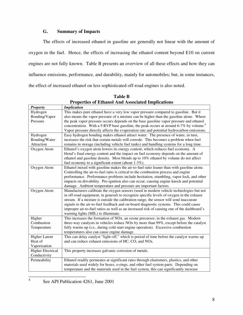
G. Summary of Impacts
The effects of increased ethanol in gasoline are generally not linear with the amount of
oxygen in the fuel. Hence, the effects of increasing the ethanol content beyond E10 on current
engines are not fully known. Table B presents an overview of all these effects and how they can
influence emissions, performance, and durability, mainly for automobiles; but, in some instances,
the effect of increased ethanol on less sophisticated off-road engines is also noted.
Table B
Properties of Ethanol And Associated Implications Property Implication
Hydrogen
Bonding/Vapor
Pressure
This makes pure ethanol have a very low vapor pressure compared to gasoline. But it
also means the vapor pressure of a mixture can be higher than the gasoline alone. Where
the peak vapor pressure occurs depends on the base gasoline vapor pressure and ethanol
concentration. With a 9 RVP base gasoline, the peak occurs at around 6-7% by volume.8
Vapor pressure directly affects the evaporation rate and potential hydrocarbon emissions.
Hydrogen
Bonding/Water
Attraction
Easy hydrogen bonding makes ethanol attract water. The presence of water, in turn,
increases the risk that certain metals will corrode. This becomes a problem when fuel
remains in storage (including vehicle fuel tanks) and handling systems for a long time.
Oxygen Atom Ethanol’s oxygen atom lowers its energy content, which reduces fuel economy. A
blend’s final energy content and the impact on fuel economy depends on the amount of
ethanol and gasoline density. Most blends up to 10% ethanol by volume do not affect
fuel economy to a significant extent (about 1-3%).
Oxygen Atom
Ethanol mixed with gasoline makes the air-to-fuel ratio leaner than with gasoline alone.
Controlling the air-to-fuel ratio is critical to the combustion process and engine
performance. Performance problems include hesitation, stumbling, vapor lock, and other
impacts on drivability. Pre-ignition also can occur, causing engine knock and potential
damage. Ambient temperature and pressure are important factors.
Oxygen Atom Manufacturers calibrate the oxygen sensors (used in modern vehicle technologies but not
in off-road equipment, in general) to recognize specific levels of oxygen in the exhaust
stream. If a mixture is outside the calibration range, the sensor will send inaccurate
signals to the air-to-fuel feedback and on-board diagnostic systems. This could cause
improper air-to-fuel ratios as well as an increased risk of causing one of the dashboard’s
warning lights (MIL) to illuminate.
Higher
Combustion
Temperature
This increases the formation of NOx, an ozone precursor, in the exhaust gas. Modern
three-way catalysts in vehicles reduce NOx by more than 99%, except before the catalyst
fully warms up (i.e., during cold-start engine operation). Excessive combustion
temperatures also can cause engine damage.
Higher Latent
Heat of
Vaporization
This can delay catalyst “light-off,” which is period of time before the catalyst warms up
and can reduce exhaust emissions of HC, CO, and NOx.
Higher Electrical
Conductivity
This property increases galvanic corrosion of metals.
Permeability Ethanol readily permeates at significant rates through elastomers, plastics, and other
materials used widely for hoses, o-rings, and other fuel system parts. Depending on
temperature and the materials used in the fuel system, this can significantly increase
8 See API Publication 4261, June 2001
9
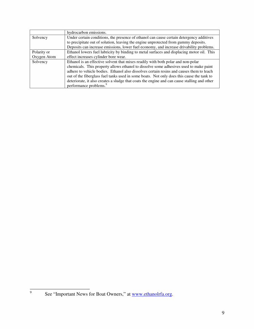
hydrocarbon emissions.
Solvency Under certain conditions, the presence of ethanol can cause certain detergency additives
to precipitate out of solution, leaving the engine unprotected from gummy deposits.
Deposits can increase emissions, lower fuel economy, and increase drivability problems.
Polarity or
Oxygen Atom
Ethanol lowers fuel lubricity by binding to metal surfaces and displacing motor oil. This
effect increases cylinder bore wear.
Solvency Ethanol is an effective solvent that mixes readily with both polar and non-polar
chemicals. This property allows ethanol to dissolve some adhesives used to make paint
adhere to vehicle bodies. Ethanol also dissolves certain resins and causes them to leach
out of the fiberglass fuel tanks used in some boats. Not only does this cause the tank to
deteriorate, it also creates a sludge that coats the engine and can cause stalling and other
performance problems.9
9 See “Important News for Boat Owners,” at www.ethanolrfa.org.
10
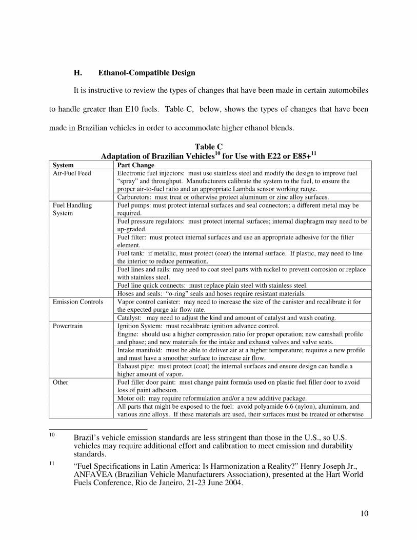
H. Ethanol-Compatible Design
It is instructive to review the types of changes that have been made in certain automobiles
to handle greater than E10 fuels. Table C, below, shows the types of changes that have been
made in Brazilian vehicles in order to accommodate higher ethanol blends.
Table C
Adaptation of Brazilian Vehicles10
for Use with E22 or E85+11
System Part Change
Electronic fuel injectors: must use stainless steel and modify the design to improve fuel
“spray” and throughput. Manufacturers calibrate the system to the fuel, to ensure the
proper air-to-fuel ratio and an appropriate Lambda sensor working range.
Air-Fuel Feed
Carburetors: must treat or otherwise protect aluminum or zinc alloy surfaces.
Fuel pumps: must protect internal surfaces and seal connectors; a different metal may be
required.
Fuel pressure regulators: must protect internal surfaces; internal diaphragm may need to be
up-graded.
Fuel filter: must protect internal surfaces and use an appropriate adhesive for the filter
element.
Fuel tank: if metallic, must protect (coat) the internal surface. If plastic, may need to line
the interior to reduce permeation.
Fuel lines and rails: may need to coat steel parts with nickel to prevent corrosion or replace
with stainless steel.
Fuel line quick connects: must replace plain steel with stainless steel.
Fuel Handling
System
Hoses and seals: “o-ring” seals and hoses require resistant materials.
Vapor control canister: may need to increase the size of the canister and recalibrate it for
the expected purge air flow rate.
Emission Controls
Catalyst: may need to adjust the kind and amount of catalyst and wash coating.
Ignition System: must recalibrate ignition advance control.
Engine: should use a higher compression ratio for proper operation; new camshaft profile
and phase; and new materials for the intake and exhaust valves and valve seats.
Intake manifold: must be able to deliver air at a higher temperature; requires a new profile
and must have a smoother surface to increase air flow.
Powertrain
Exhaust pipe: must protect (coat) the internal surfaces and ensure design can handle a
higher amount of vapor.
Fuel filler door paint: must change paint formula used on plastic fuel filler door to avoid
loss of paint adhesion.
Motor oil: may require reformulation and/or a new additive package.
Other
All parts that might be exposed to the fuel: avoid polyamide 6.6 (nylon), aluminum, and
various zinc alloys. If these materials are used, their surfaces must be treated or otherwise
10
Brazil’s vehicle emission standards are less stringent than those in the U.S., so U.S. vehicles may require additional effort and calibration to meet emission and durability standards.
11 “Fuel Specifications in Latin America: Is Harmonization a Reality?” Henry Joseph Jr.,
ANFAVEA (Brazilian Vehicle Manufacturers Association), presented at the Hart World Fuels Conference, Rio de Janeiro, 21-23 June 2004.
11
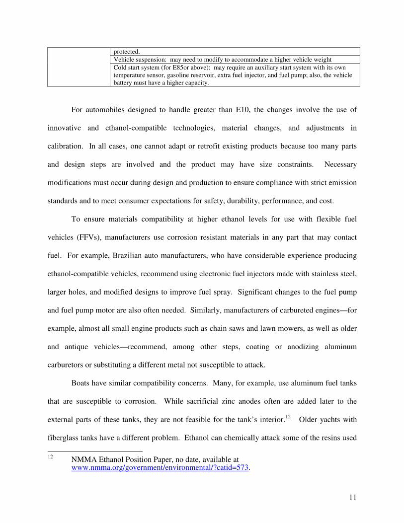
protected.
Vehicle suspension: may need to modify to accommodate a higher vehicle weight
Cold start system (for E85or above): may require an auxiliary start system with its own
temperature sensor, gasoline reservoir, extra fuel injector, and fuel pump; also, the vehicle
battery must have a higher capacity.
For automobiles designed to handle greater than E10, the changes involve the use of
innovative and ethanol-compatible technologies, material changes, and adjustments in
calibration. In all cases, one cannot adapt or retrofit existing products because too many parts
and design steps are involved and the product may have size constraints. Necessary
modifications must occur during design and production to ensure compliance with strict emission
standards and to meet consumer expectations for safety, durability, performance, and cost.
To ensure materials compatibility at higher ethanol levels for use with flexible fuel
vehicles (FFVs), manufacturers use corrosion resistant materials in any part that may contact
fuel. For example, Brazilian auto manufacturers, who have considerable experience producing
ethanol-compatible vehicles, recommend using electronic fuel injectors made with stainless steel,
larger holes, and modified designs to improve fuel spray. Significant changes to the fuel pump
and fuel pump motor are also often needed. Similarly, manufacturers of carbureted engines—for
example, almost all small engine products such as chain saws and lawn mowers, as well as older
and antique vehicles—recommend, among other steps, coating or anodizing aluminum
carburetors or substituting a different metal not susceptible to attack.
Boats have similar compatibility concerns. Many, for example, use aluminum fuel tanks
that are susceptible to corrosion. While sacrificial zinc anodes often are added later to the
external parts of these tanks, they are not feasible for the tank’s interior.12
Older yachts with
fiberglass tanks have a different problem. Ethanol can chemically attack some of the resins used
12
NMMA Ethanol Position Paper, no date, available at www.nmma.org/government/environmental/?catid=573.
12
to make these tanks causing them to dissolve. In doing so, the ethanol causes leaks, heavy black
deposits on marine engine intake valves, and deformation of push rods, pistons, and valves.13
Conventional vehicles and products do not have these material adaptations for higher
level ethanol use. One device particularly difficult to address after-the-fact is the fuel tank level
sensor. These sensors, which are placed inside the fuel tank, directly expose wiring to the fuel.
Depending on how much ethanol these devices contact and for how long, galvanic or electrolytic
corrosion would be expected to dissolve the wires and eventually cause device failure.
Manufacturers make additional design changes to address emissions and performance
needs.14
In this context, it is important to remember that U.S. emission standards are more
stringent than those in Brazil. For U.S. vehicles, manufacturers select oxygen sensors and
onboard diagnostic (OBD) systems specifically to cover the expected range of oxygen in the
exhaust gas. If the fuel ethanol pushes the exhaust oxygen content outside the range of the
oxygen sensor, the vehicle’s OBD system won’t work properly and may erroneously illuminate
or fail to illuminate the dashboard warning light. In addition, manufacturers must calibrate
vehicle and product systems to the expected fuel to ensure the proper air-fuel ratio for both
emissions and performance purposes. In the U.S., off-road engines are also regulated for
emissions regardless of their size or equipment that they power. Generally, the off-road engines
do not utilize oxygen sensors and computer controls to adjust fuel delivery by a closed loop
system. In many products, emission compliance has dictated air-to-fuel ratio controls that are a
delicate balance between being too rich and, therefore, out of compliance, or too lean, resulting
in performance or durability problems.
13
Id. 14
“Fuel Specifications in Latin America: Is Harmonization a Reality?” Henry Joseph Jr., ANFAVEA (Brazilian Vehicle Manufacturers Association), presented at the Hart World Fuels Conference, Rio de Janeiro, 21-23 June 2004.
13
The long term durability of emission control systems is a critical issue, with current U.S.
federal and California emission standards requiring on-road vehicles to comply for up to 150,000
miles and off-road engines to comply for full useful life periods. If the control system of the
vehicle was not designed to accommodate the leaning effect of ethanol, the vehicle’s catalyst
protection routine will be disabled. For off-highway engines, or older vehicles without closed
loop systems, the enleanment influence can result in higher exhaust gas temperatures. This can
cause thermal degradation of the catalyst over time, either through sintering of the precious metal
wash-coat or damage to the substrate and can also degrade critical engine components such as
pistons and exhaust valves.

E:\COMMENTS ON E15 WAIVER APPLICATION\EXHIBIT
B - SUPPLEMENTAL STATUTORY APPENDIX.DOC
EXHIBIT B
E:\COMMENTS ON E15 WAIVER
APPLICATION\EXHIBIT B - SUPPLEMENTAL
STATUTORY APPENDIX.DOC
2
Supplemental Statutory Appendix
To the Comments of the Alliance for a Safe Alternative Fuels Environment
On the Request for Waiver of the Prohibition in Section 211(f)(1) of the Clean Air Act
Noticed for Comment at 74 Fed. Reg. 18,228 (April 21, 2009)
E:\COMMENTS ON E15 WAIVER APPLICATION\EXHIBIT
B - SUPPLEMENTAL STATUTORY APPENDIX.DOC i
Table of Contents
I. Judicial Precedent under Clean Air Act Section 211(f)(4) Governing the
Application..........................................................................................................................1
A. Background...................................................................................................................1
B. The Current Application .............................................................................................3
II. The Relationship Between Section 211 and the Vehicle and Engine Remedial
Provisions of the Clean Air Act. .......................................................................................6
E:\COMMENTS ON E15 WAIVER
APPLICATION\EXHIBIT B - SUPPLEMENTAL
STATUTORY APPENDIX.DOC
1
This Appendix to the Comments of the Alliance for a Safe Alternative Fuels
Environment (“AllSAFE”) provides additional analysis of the statutory provisions that should
govern EPA’s consideration of the application for a waiver under Clean Air Act section
211(f)(4) for gasoline-ethanol blends containing 15 percent ethanol by volume (E15)
submitted March 6, 2009 (“the Application”).
Part I of this Appendix outlines the judicial precedents establishing what an applicant
must prove in order to meet the standards for a waiver under section 211(f)(4). Part II of the
Appendix relates the requirements of section 211(f)(4) to the obligations of on-road vehicle
and engine manufacturers to provide remedies for class-wide nonconformities with emissions
standards, pursuant to Clean Air Act section 207(c)(1) and regulations adopted by EPA for
non-road vehicles and engines under Clean Air Act section 213. The analysis in Part II is
premised on an assumption that EPA may choose or will be required in the future to consider
additional applications for a waiver under section 211(f)(4) for E15 or other ethanol blends, or
may be considering taking some other action that might permit the lawful sale of ethanol
blends with greater than 10 percent ethanol by volume.
I. Judicial Precedent under Clean Air Act Section 211(f)(4) Governing the
Application
A. Background
As amended by the Energy Independence and Security Act of 2007, Pub. L. No. 110-
140, 121 Stat 1492 (2007) (the “2007 Energy Act”), Clean Air Act section 211(f)(4) provides
in pertinent part as follows:
The Administrator, upon application of any manufacturer of any
fuel or fuel additive, may waive the prohibitions established
under … this subsection, if he determines that the applicant has
established that such fuel or fuel additive or a specified
concentration thereof, and the emission products of such fuel or
E:\COMMENTS ON E15 WAIVER
APPLICATION\EXHIBIT B - SUPPLEMENTAL
STATUTORY APPENDIX.DOC
2
fuel additive or specified concentration thereof, will not cause
or contribute to a failure of any emission control device or
system … to achieve compliance by the vehicle or engine with
the emission standards with respect to which it has been
certified pursuant to sections 206 and 213(a).
42 U.S.C. § 7545(f)(4) (emphasis added); see also id. (applicant must establish no such
contribution to failures over the “useful life” of vehicles or engines).
An applicant for a waiver under section 211(f)(4) has the “clear burden” of
establishing that a nonconforming fuel or blend will not cause or contribute to the failure of
an emissions control system to meet applicable EPA standards at any point during the useful
life of the vehicle. See, e.g., Motor Vehicle Mfr’s Ass’n v. EPA, 768 F2d 385, 388 n.4 (D.C.
Cir. 1985) (“MVM 1985”). This does not require a waiver applicant to prove that a given
fuel, additive or blend will not contribute to any failure of emissions control systems to meet
applicable standards. Instead, the applicant is required to use a “reliable statistical sampling
[method] and “fleet testing protocols” to demonstrate no contribution to “significant failures”
to meet those standards. As EPA explained its position in the Petrocoal Waiver matter that
was the subject of the MVMA 1985 decision:
This burden [of proving no impact on emissions compliance],
which Congress has imposed on the applicant, if interpreted
literally, is virtually impossible to meet as it requires proof of a
negative proposition, i.e., that no vehicle will fail to meet
emission standards with respect to which it has been certified.
Taken literally, it would require the testing of every vehicle.
Recognizing that Congress contemplated a workable waiver
provision, mitigation of this stringent burden was deemed
necessary. For purposes of the waiver provision, EPA has
previously indicated that reliable statistical sampling and fleet
testing protocols may be used to demonstrate that a fuel under
consideration would not cause or contribute to a significant
failure of emission standards by vehicles in the national fleet.
E:\COMMENTS ON E15 WAIVER
APPLICATION\EXHIBIT B - SUPPLEMENTAL
STATUTORY APPENDIX.DOC
3
46 Fed. Reg. 48,975, 48,976 (Oct. 5, 1981), quoted in MVMA 1985, 768 F.2d at 391. The
MVMA 1985 court ultimately concluded that EPA had not actually required the use of the
requisite “reliable statistical sampling and fleet testing protocols” in granting a waiver for
Petrocoal, and reversed EPA’s decision granting that waiver. Id. at 402
Since 1985, every subsequent waiver proceeding under section 211(f)(4) reviewed in
the court of appeals has largely depended on whether (i) the applicant used “reliable” statistics
for the relevant “fleet” of vehicles, and (ii) whether EPA’s analysis of the data was
reasonable. See, e.g., Ethyl Corp. v. EPA, 51 F.3d 1053, 1064 (D.C. Cir. 1995) (“Ethyl
1995”) (directing EPA to grant waiver, when Agency had accepted data from most extensive
testing program in history of waiver proceedings showing that additive would not contribute
to “a significant level of emissions failures”). The applicant has the burden of proof, but the
burden is satisfied by demonstrating that the nonconforming fuel will not cause or contribute
to “significant” failures. The proper construction of “significant” in this context is examined
in Part II. Before examining that question, it is important to review the salient features of the
current Application.
B. The Current Application
For the reasons outlined in the main text of these comments, the Application cannot be
approved. Any decision by EPA approving the Application would not withstand judicial
review. In brief:
1. The relevant “fleet” of vehicles and engines has not been fully tested. MVMA
requires sound “fleet testing protocols.” The data contained in the Application does not
cover the entire “fleet” of vehicles and engines that would be exposed to E15 as a general-
purpose fuel. Congress made it clear in the 2007 Energy Act that all vehicles and engines
E:\COMMENTS ON E15 WAIVER
APPLICATION\EXHIBIT B - SUPPLEMENTAL
STATUTORY APPENDIX.DOC
4
meeting EPA standards that might encounter a nonconforming fuel must be included in the
necessary fleet testing protocol. That was the purpose of the amendment to section 211(f)(4)
included in the 2007 Energy Act. (See Main Comments at xxx, xxx.)
2. The limited portions of the relevant fleet that have been tested have not been tested
in a statistically useful or meaningful way. The Application contains no data demonstrating
the impact, or lack of impact, on the ability of the tested vehicles and engines to meet each of
the applicable emissions standards over full useful life. None of the on-road vehicle testing
cited in the Application covers the range of useful-life FTP, Supplemental FTP, I/M and
onboard diagnostics testing that vehicles manufacturers are required to apply in determining
whether their vehicles meet EPA’s emissions standards. The Applications’ reliance on the
interim Department of Energy vehicle test results that it cites is completely misplaced,
because the Energy Department vehicle testing did not use any of the test procedure that EPA
uses to determine compliance with emissions standards. Cf. Portland Cement Ass’n v.
Ruckelshaus, 375, 396 (D.C. Cir. 1973) (test procedures that will be used to determine
compliance with emission standards must be used in agency determinations of feasibility of
standards).
Several other comments on the Application are in order. The Application is wrong or
misleading in suggesting that EPA has “repeatedly” granted waiver applications without
requiring tests that reliably predict evaporative emissions performance and impacts on
evaporative control system components. (See Application at 26.) Since the onset of
significant evaporative emissions control requirements, such testing has been routinely
required and sufficient to represent the entire relevant fleet in the case of alcohol blends.
E:\COMMENTS ON E15 WAIVER
APPLICATION\EXHIBIT B - SUPPLEMENTAL
STATUTORY APPENDIX.DOC
5
The Application is also not correct in ignoring the need for a statistical method
projecting emissions performance at the end of useful life. The data in Orbital Engineering’s
reports, as well as the interim Department of Energy data, provide prima facie evidence of
accelerated losses in efficiency owing to higher exotherms in the converters used in some
modern emissions control systems. (See Main Text at xxx.) When the relevant effects can
include accelerated catalyst deterioration, “back to back” testing to determine so-called
“instantaneous” emissions impacts is not sufficient. Cf. MVMA 1985, 768 F.2d at 392-93.
As the MVMA 1985 court stated, in an era when 50,000 miles marked the end of the relevant
“useful life:”
Section 211(f)(4) only requires that the EPA determine that a
fuel will not cause or contribute to a failure of an emission
device to comply with applicable emission standards during a
vehicle's useful life, it does not specify that the EPA must base
this determination on actual 50,000-mile durability tests in all
cases. Nonetheless, given section 211(f)(4)'s clear directive
that the EPA must evaluate the effect of a fuel over the useful
life of a vehicle, the EPA must have a clearly sound basis for
determining in a given case that back-to-back testing provides
an adequate and sufficient means of evaluation in lieu of
actual 50,000-mile testing.
768 F.2d at 392-93. Even for the limited population of vehicles and engines included in the
few portions of the Application that rely on documented tests, there is no discussion of how
deterioration factors might be applied to the relevant data points, much less a demonstration
that the increases in emissions of oxides of nitrogen shown in Orbital’s testing would not
contribute to significant failures at the end of useful life.
Finally, without expressing a view on the public policy objectives cited in support of
the Application, it bears noting that EPA “may not simply disregard the specific scheme
Congress has created for the regulation of fuels” in pursuit of objectives outside the limits of
E:\COMMENTS ON E15 WAIVER
APPLICATION\EXHIBIT B - SUPPLEMENTAL
STATUTORY APPENDIX.DOC
6
section 211(f)(4). Id. at 1060 n.9; see also id. at 1055 (“The language of section 211(f)(4) is
clear, directing the Administrator to consider only emissions effects in determining what
action to take on a waiver request).
In sum, a decision to approve the Application based on the data proffered in the
Application would lack “any rational basis” and could not be affirmed. MVMA 1985, 768
F.2d at 393. Because the Agency has indicated that it seeks comments on alternative means
of increasing the ethanol content of gasoline in general use, it is also important to consider
such strategies in the full statutory context outlined in Part II below. 1
II. The Relationship Between Section 211 and the Vehicle and Engine Remedial
Provisions of the Clean Air Act.
The overall goal of title II of the Clean Air Act is to assure the control of in-use
emissions from vehicles and engines, based on full useful-life standards set by EPA pursuant
to its delegated authority from Congress. That goal can be frustrated in many ways. One is
by the introduction of fuels, additives, or blends that contribute to a significant number of
emissions failures. In section 211(f)(4), “Congress adopted a preventative approach” and
carefully limited the grounds on which EPA could allow fuel and additive manufacturers to
introduce new, nonconforming fuels into commerce Ethyl 1995, 51 F.3d at 1055.
After repairing the evident deficiencies in the current Application, parties seeking
permission for the energy industry to use blends of ethanol higher than E10 will undoubtedly
try to claim that any emissions failures that may result will not be “significant.” Indeed, they
must prove that such failures will not be significant in order to obtain a waiver. In denying
1 For example, in its Notice of Proposed Rulemaking to implement amended section 211(o)
of the Clean Air Act, EPA indicates that it may consider defining a blend such as E12 as
“substantially similar” to currently authorized fuels for some motor vehicles. See 74 Fed.
Reg. 24,904, 25,019 (May 26, 2009).
E:\COMMENTS ON E15 WAIVER
APPLICATION\EXHIBIT B - SUPPLEMENTAL
STATUTORY APPENDIX.DOC
7
the current Application, EPA would well-serve all stakeholders by clarifying what
“significant” means in this context.
The starting point for that clarification should be the provisions of the Clean Air Act
that articulate the vehicle and engine industries’ duties to ensure compliance with EPA’s
emissions standards. The bedrock provision of title II in this regard is section 207(c)(1) of
the Clean Air Act, which provides in pertinent part as follows:
If the Administrator determines that a substantial number of
any class or category of vehicles or engines, although properly
maintained and used, do not conform to the regulations
prescribed under section 202, when in actual use throughout
their useful life (as determined under section 202(d), he shall
immediately notify the manufacturer thereof of such
nonconformity, and he shall require the manufacturer to submit
a plan for remedying the nonconformity of the vehicles or
engines with respect to which such notification is given. The
plan shall provide that the nonconformity of any such vehicles
or engines which are properly used and maintained will be
remedied at the expense of the manufacturer.
42 U.S.C. § 7541(c)(1) (emphasis added). 2
Section 207(c)(1), strikes a balance “among competing goals of consumer
convenience, improved air quality, and the technical accuracy which would insure that
manufacturers are not forced to repair significant numbers of properly functioning vehicles.”
Motor Vehicle Mfr’s Ass’n v. Ruckelshaus, 719 F.2d 1169, 1168 (D.C. Cir. 1983) (“MVMA
1983”) (emphasis added; internal quotation marks omitted). A vehicle or engine
manufacturer “incurs heavy costs -- both financial and goodwill -- simply by issuing [a recall]
2 EPA has written similar criteria for remedial action into its non-road regulations adopted
under section 213. See, e.g.,40 C.F.R. § 90.808 (limiting recall authority to cases in
which “substantial number” of engines in a defined class or category subject to Part 90
standards and test procedures do not conform with the Part 90 standards).
E:\COMMENTS ON E15 WAIVER
APPLICATION\EXHIBIT B - SUPPLEMENTAL
STATUTORY APPENDIX.DOC
8
notice to owners.” General Motors Corp. v. Ruckelshaus, 742 F.2d 1561, 1566 n.7 (D.C. Cir
1984) (en banc).
Accordingly, section 207(c)(1) only permits “classwide remedies” in response to
“classwide defects.” General Motors, 742 F.2d at 1568. As in section 211(f)(4) proceedings,
the use of reliable statistics is critical in determining whether a recall can be ordered under
section 207(c)(1).3 Recalls cannot be not required for nonconformities that do not appear in a
“substantial number” of vehicles in a given class, which MVMA 1983 equated to a
“significant numbers” of vehicles.
Equally important, the court of appeals has recognized that Congress did not intend to
impose recall liability on manufacturers, even for class-wide emissions failures in a
substantial or significant number of vehicles, if those failures could not have been reasonably
avoided by the manufacturer. As Chief Judge Wright explained in 1980, “Unless the cause of
the nonconformity is within the manufacturer’s control, an imposition of liability would be an
unwarranted financial burden on the manufacturers, unrelated to the strategy of forcing
technological progress.” Chrysler Corp. v. EPA, 631 F.2d 865, 888 (D.C. Cir. 1980).
Combining those two strands of case law under section 207(c)(1), the only reasonable
way to understand the term “significant failures” in EPA’s section 211(f)(4) doctrine is as
follows: a waiver applicant under section 211(f)(4) has the burden of proving that any level
of failure in the relevant vehicle and engine population will not rise to a class-wide level that
EPA could treat as “substantial” enough to warrant an ordered recall. Otherwise, vehicle and
3 Congress expected EPA to define the recall “class or category” by reference to a
“representative sample” of vehicles. Summary of the Provisions of Conference
Agreement on the Clean Air Act Amendments of 1970, reprinted in 116 Cong. Rec.
42,384 (1970).
E:\COMMENTS ON E15 WAIVER
APPLICATION\EXHIBIT B - SUPPLEMENTAL
STATUTORY APPENDIX.DOC
9
engine manufacturers will be made responsible for emissions failures and recalls based on
conditions beyond their control, in violation of the liability rule established in the 1980
Chrysler decision.
Because it is impractical to make a party seeking a section 211(f)(4) waiver generally
responsible for in-use emissions failures that warrant recalls or other remedies, it is critical for
EPA to determine up-front, before granting a waiver, that the relevant fuel, additive or blend
will not contribute to a substantial failure rate in the relevant vehicle population. Stated
another way, the statistical demonstration needed to support a recall order under section
207(c)(1) should define the proof needed to grant a waiver under section 211(f)(4). That is
the only way that EPA can effectuate the “preventative approach” embodied in section
211(f)(4) that recognizes the limits on its recall and remedial powers with respect to vehicles
and engines. Once EPA grants a waiver under section 211(f)(4) for a given fuel, additive or
blend, it cannot therefore properly order a recall or other remedy for in-use emissions failures
that can be attributed to that fuel, additive or blend. Likewise, any EPA determination that a
blend greater than E10 is “substantially similar” to E10 (such as E120 must necessarily rest on
the premise that any failures in the in-use vehicle population to which the higher ethanol
blend contributed would not be substantial enough to warrant a recall or other remedial action.

EXHIBIT C
Mechanical Components Department
04-27-2007
Kevin Goplen, Phone (414) 774-4622, Fax (414) 259-5321, E-mail: [email protected]
Minnesota E20 EPA Fuel Waiver Evaluation - Quantum
Revisions Date: 4/27/2007 - Written by Kevin Goplen 5/4/2007 - Kevin Goplen added M10 stability testing results. 5/14/2007 – Kevin Goplen revised chart on page 23. Background Minnesota state legislature is mandating the use of gasoline containing 20% by volume ethanol (E20) to replace current gasoline containing 10% by volume ethanol (E10) by August 30, 2013. E20 poses a problem for off highway engines due to enleanment of the air/fuel mixture in carbureted, open loop systems. Conclusion Initial testing indicates that E20 is not substantially similar to E0 under Section 211 of the Federal Clean Air Act. The following is a summary of conclusions for each test: Materials Compatibility Fuel Soaking - E20 is not compatible with some fuel system components, especially fibrous and rubber gaskets. Failure of these components will cause fuel to leak contributing to evaporative emissions and pose a safety hazard. Temperature Testing - Higher operating temperatures experienced with E20 leads to problems such as head gasket failure and vapor lock. Drivability and Performance Stability - Strip Chart Testing - Enleanment from the extra oxygen in E20 decreased stability leads to poor performance, such as harsh audible rpm oscillation, for the end-user. Starting - Strip Chart Testing - Slower acceleration leads to poor load acceptance and reduces performance for the end-user. Horsepower and Torque Testing - E20 showed a negligible increase in peak horsepower of approximately 2% and negligible change in peak torque. Emissions Exhaust Emissions - E20 HC + NOX increased 10.5%. A carburetor calibration would be required to maintain current levels. Evaporative Emissions - To be completed
Page 1 of 24Project 05_054 – E20 EPA Fuel Waiver Minnesota Printed copies of this report are uncontrolled
Mechanical Components Department
04-27-2007
Health and Safety Issues - No testing to date One of the major concerning issues is the 10.50% increase in weighted HC + NOX. The increased oxygen content in ethanol accounts for a leaner air/fuel mixture. In order to obtain the correct air/fuel ratio using E20 a carburetor calibration is required. For E20 to be considered substantially similar to E0, E20 must be backwards compatible with product that is currently in use in the field. Thus, the use of E20 in existing engines would require tampering with an emissions control devise in order to maintain HC + NOX levels and thus violate the Federal Clean Air Act. Recommendations E20 should not be considered substantially similar to E0 due to the increase in exhaust emissions and required carburetor calibration, the decrease in rpm stability, and material incompatibility. Procedure E20 fuel specifications do not exist and need to be determined. The Code of Federal Regulations (CFR) and ASTM specifications are not established for E20 fuel. Specifications are needed for vapor pressure, volatility, and additive packages that include corrosion and oxidation inhibitors and their required concentrations. E22 Brazilian Yellow fuel is the closest legal option to E20. The assumption has been made that E22 Brazilian Yellow is representative of future specifications of E20 fuel. E22 Brazilian Yellow is used for all testing and is referred to as E20 in the entirety of this report. The Certificate of Analysis for E22 Brazilian Yellow is included at the end of this report. To determine the specific problems associated with the use of E20 in small off-road engines E20 is being tested vs. E10 vs. Non-reformulated gasoline (E0) using a 6.0 HP Quantum engine (engine 123K02 0239E1 04061458 was used for all testing except exhaust emissions). The EPA registration process of E20 consists of four categories of testing: Materials compatibility, Drivability and Performance, Emissions (exhaust and evaporative), and Health and Safety. The following outlines the testing completed, in progress, and planned: Materials Compatibility Fuel Soaking Temperature Testing Drivability and Performance Stability - Strip Chart Testing Starting - Strip Chart Testing Horsepower and Torque Testing Emissions Exhaust Emissions Evaporative Emissions
Page 2 of 24Project 05_054 – E20 EPA Fuel Waiver Minnesota Printed copies of this report are uncontrolled
Mechanical Components Department
04-27-2007
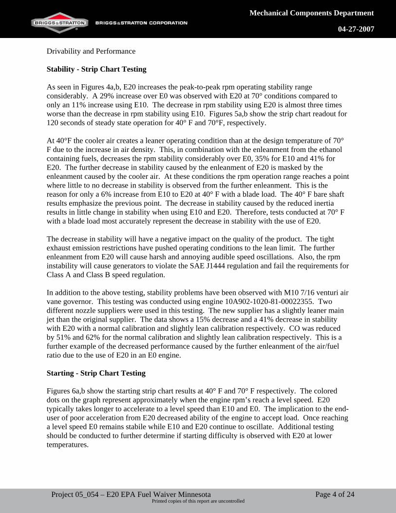
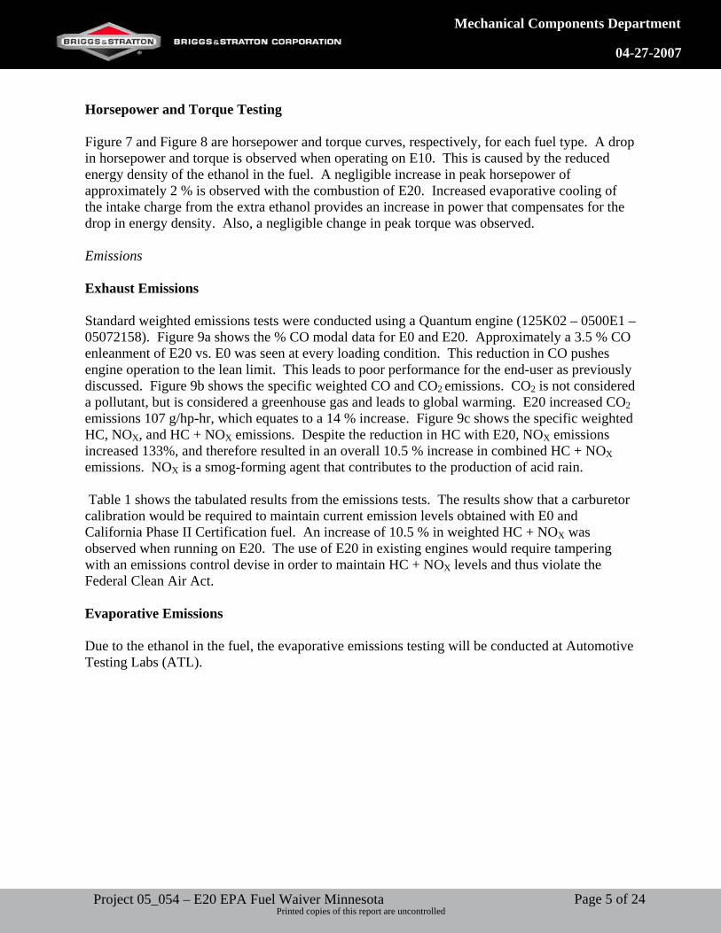
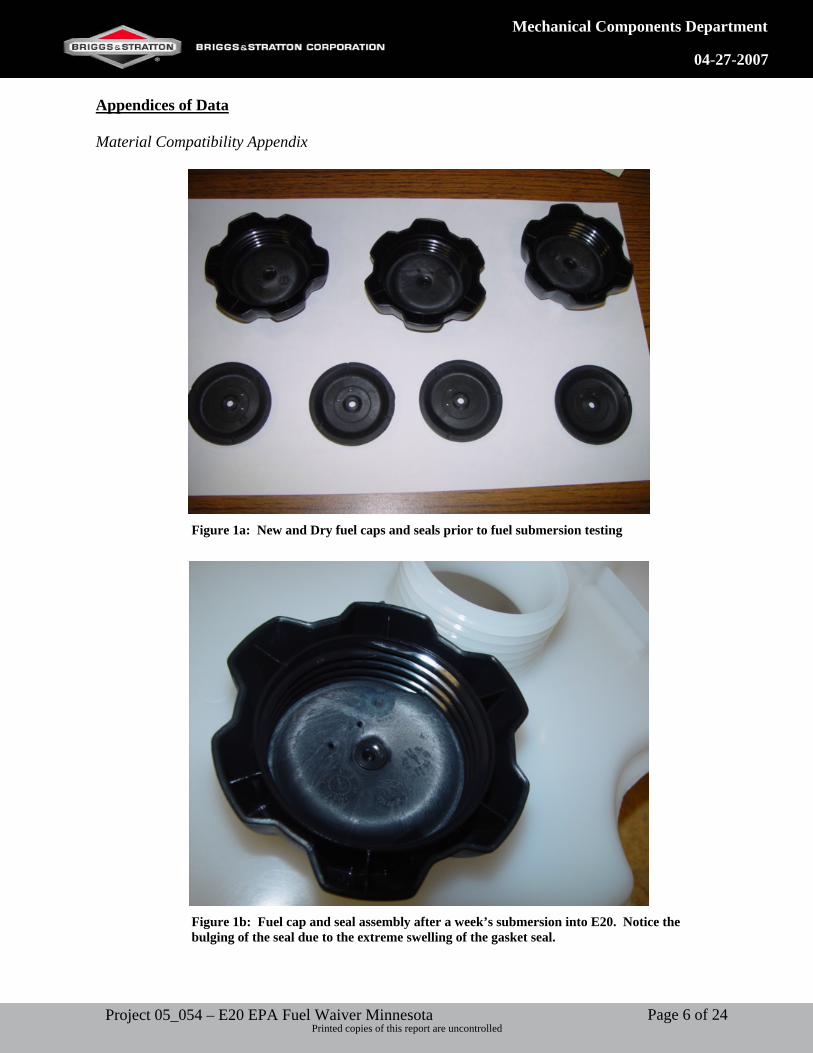
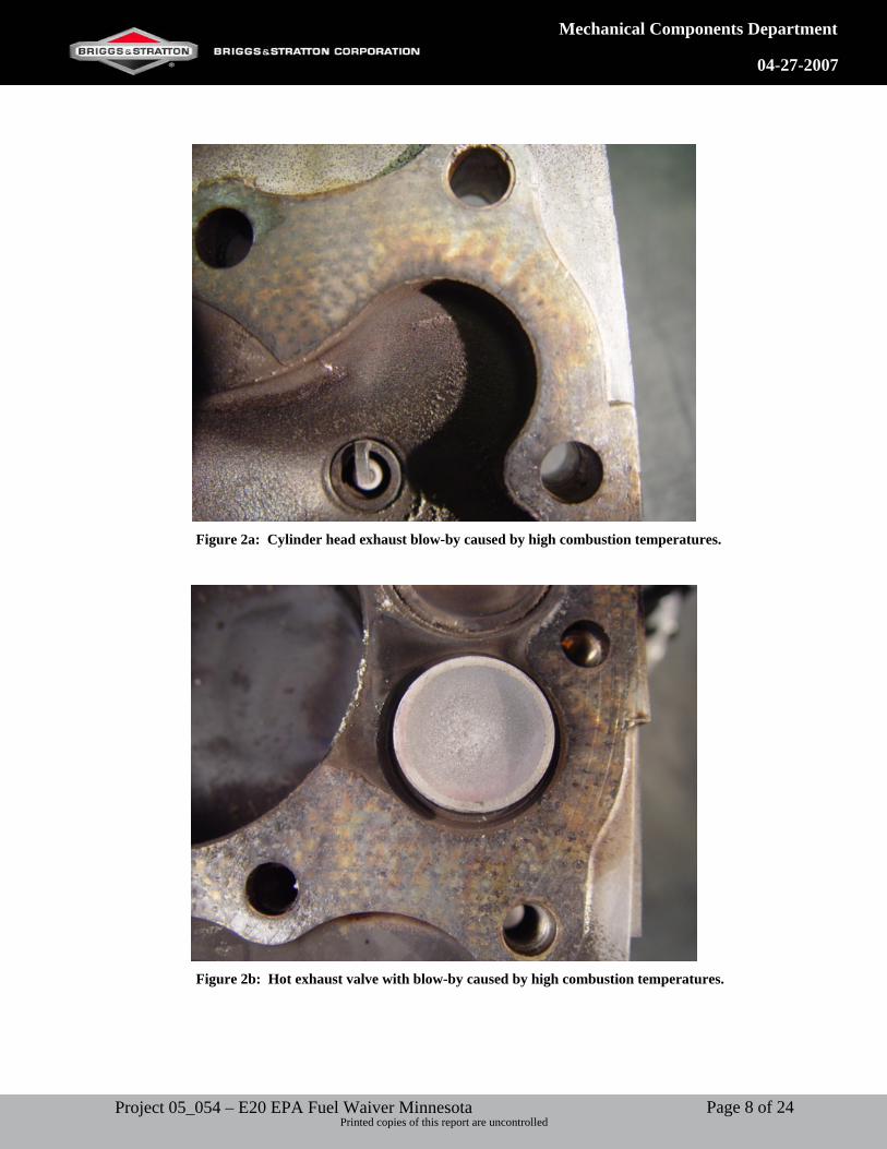
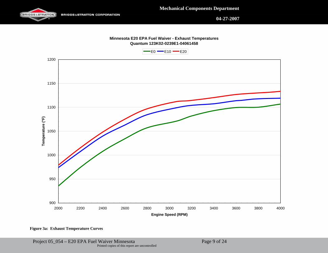
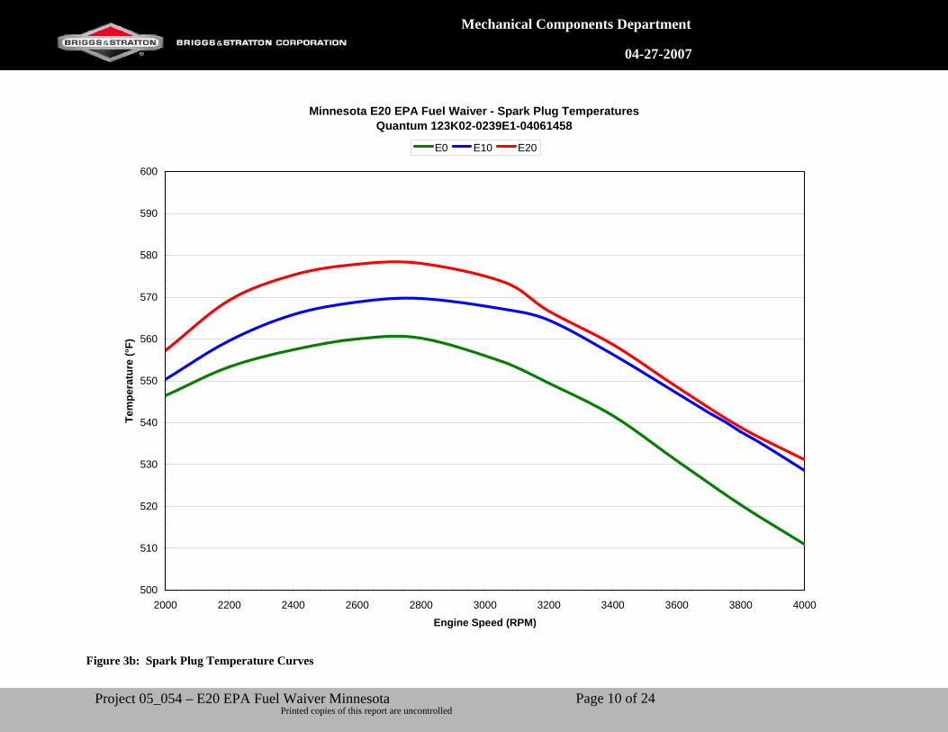
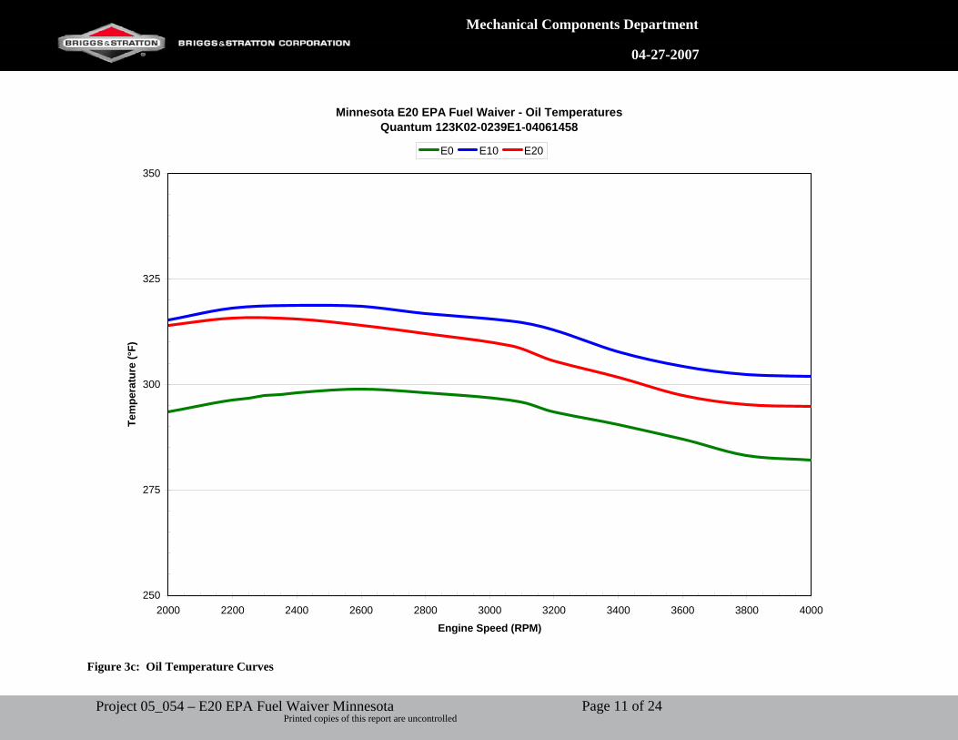
Health and Safety Issues No testing to date. Results Material Compatibility Fuel Soaking Fibrous and rubber gaskets have been observed to need frequent replacement during testing of E20 fuel. These gaskets include the fuel bowl nut gasket and the fuel bowl gasket. The failure of either of these gaskets causes fuel to leak from the carburetor. Leaking fuel increases evaporative emissions and present a danger to the consumer. A controlled study on the affects of different levels of ethanol has also been conducted. A fuel soak test was performed on all parts that come into direct contact with the fuel. These parts include carburetor bodies of zinc and aluminum, brass fuel metering jets, rubber and fiber gaskets, rubber primer bulbs, floats, and fuel bowls. These parts were soaked in three different fuel samples: E0, E10, and E20. This test does not expose differences at the same rate as does actually running due to the controlled environment in a sealed jar with minimal exposure to the air to promote oxidation. After six months of testing the affects of the different fuels became more apparent. E20 caused the gaskets and rubber parts to swell and gain mass by approximately 5 – 10% more than E0. Primer bulbs and fuel nut gaskets were affected the most of the parts. On the carburetor bodies the epoxy that holds the Welch plug in place over the progression holes was severely attacked by the E20 and caused the epoxy to dissolve and cover the entire Welch plug surface. While the plug did not fall out, on a running engine this could occur and cause fuel to leak from the carburetor. The inlet needle seats also swelled and could cause the needle to not make a solid seal, which could also cause a fuel leak. Fuel cap gaskets swelled to the point of becoming nonfunctional and prevented the caps from being completely tightened, which also increases evaporative emissions. Another fuel soak test was conducted on garden tractor fuel tank caps and seals. It was found that the samples soaked in E20 exhibited extreme swelling compared to samples soaked in E0. Figure 1a shows the dry caps and seals prior to soaking. Figures 1b,c show the extreme swell as a result of the E20 soak. Temperature Testing The excess oxygen present in the fuel causes a hotter combustion and results in a higher operation temperature. The higher temperature causes material compatibility issues. For example, head gasket failure was observed after only 25 hours of very light duty testing. Figures 2a,b are photographs of the failure area around the exhaust valve. The photos clearly show the failure due to high temperatures at the exhaust valve and the location of where gasses started to escape past the gasket. The increased operation temperatures of E20 can be seen in Figures 3a-c.
Page 3 of 24Project 05_054 – E20 EPA Fuel Waiver Minnesota Printed copies of this report are uncontrolled
Mechanical Components Department
04-27-2007
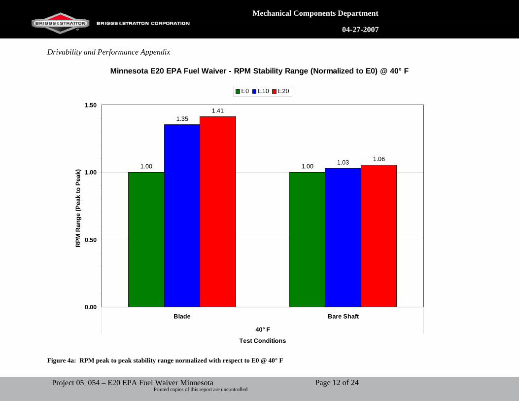
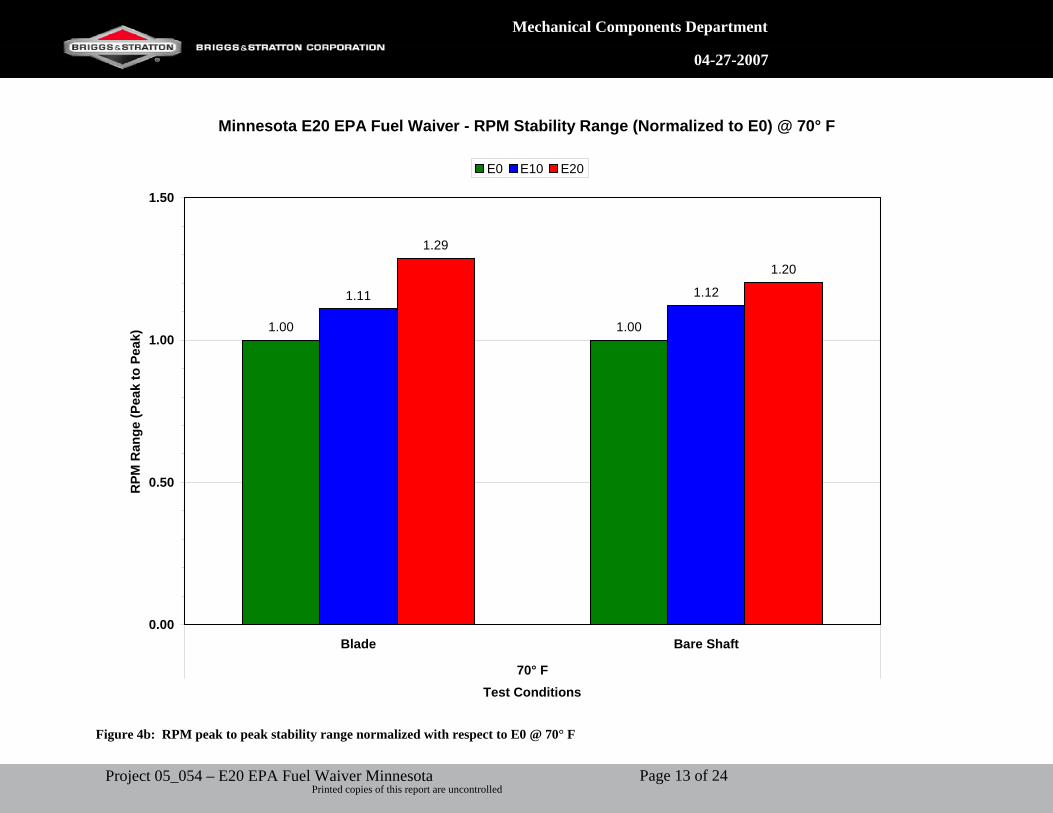
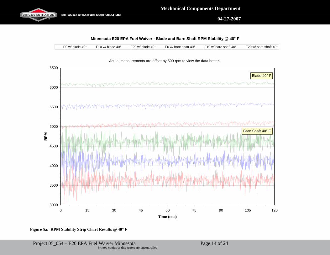
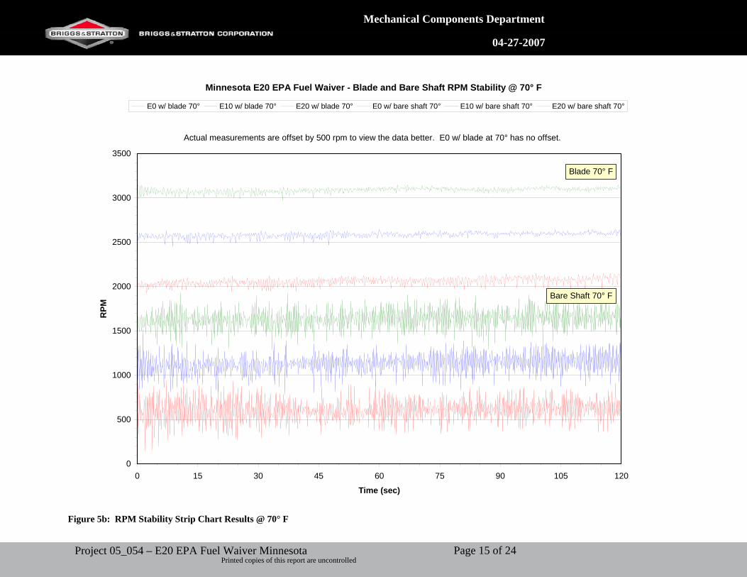
Drivability and Performance Stability - Strip Chart Testing As seen in Figures 4a,b, E20 increases the peak-to-peak rpm operating stability range considerably. A 29% increase over E0 was observed with E20 at 70° conditions compared to only an 11% increase using E10. The decrease in rpm stability using E20 is almost three times worse than the decrease in rpm stability using E10. Figures 5a,b show the strip chart readout for 120 seconds of steady state operation for 40° F and 70°F, respectively. At 40°F the cooler air creates a leaner operating condition than at the design temperature of 70° F due to the increase in air density. This, in combination with the enleanment from the ethanol containing fuels, decreases the rpm stability considerably over E0, 35% for E10 and 41% for E20. The further decrease in stability caused by the enleanment of E20 is masked by the enleanment caused by the cooler air. At these conditions the rpm operation range reaches a point where little to no decrease in stability is observed from the further enleanment. This is the reason for only a 6% increase from E10 to E20 at 40° F with a blade load. The 40° F bare shaft results emphasize the previous point. The decrease in stability caused by the reduced inertia results in little change in stability when using E10 and E20. Therefore, tests conducted at 70° F with a blade load most accurately represent the decrease in stability with the use of E20. The decrease in stability will have a negative impact on the quality of the product. The tight exhaust emission restrictions have pushed operating conditions to the lean limit. The further enleanment from E20 will cause harsh and annoying audible speed oscillations. Also, the rpm instability will cause generators to violate the SAE J1444 regulation and fail the requirements for Class A and Class B speed regulation. In addition to the above testing, stability problems have been observed with M10 7/16 venturi air vane governor. This testing was conducted using engine 10A902-1020-81-00022355. Two different nozzle suppliers were used in this testing. The new supplier has a slightly leaner main jet than the original supplier. The data shows a 15% decrease and a 41% decrease in stability with E20 with a normal calibration and slightly lean calibration respectively. CO was reduced by 51% and 62% for the normal calibration and slightly lean calibration respectively. This is a further example of the decreased performance caused by the further enleanment of the air/fuel ratio due to the use of E20 in an E0 engine.
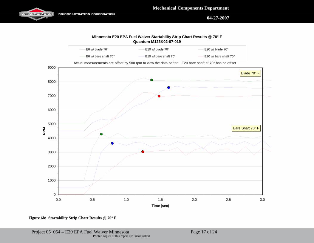
Starting - Strip Chart Testing Figures 6a,b show the starting strip chart results at 40° F and 70° F respectively. The colored dots on the graph represent approximately when the engine rpm’s reach a level speed. E20 typically takes longer to accelerate to a level speed than E10 and E0. The implication to the end-user of poor acceleration from E20 decreased ability of the engine to accept load. Once reaching a level speed E0 remains stabile while E10 and E20 continue to oscillate. Additional testing should be conducted to further determine if starting difficulty is observed with E20 at lower temperatures.
Page 4 of 24Project 05_054 – E20 EPA Fuel Waiver Minnesota Printed copies of this report are uncontrolled
Mechanical Components Department
04-27-2007
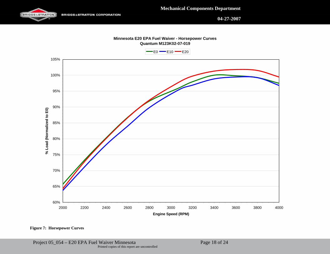
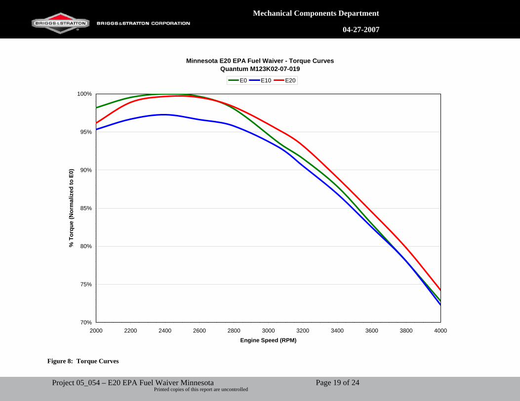
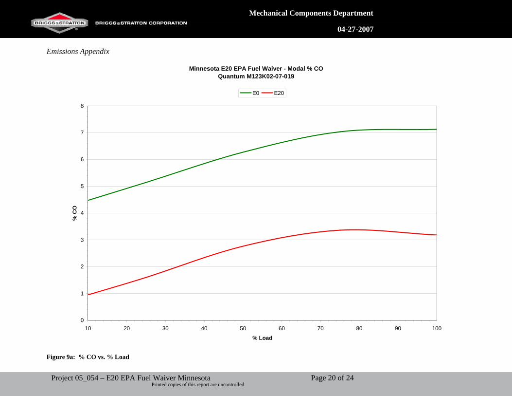
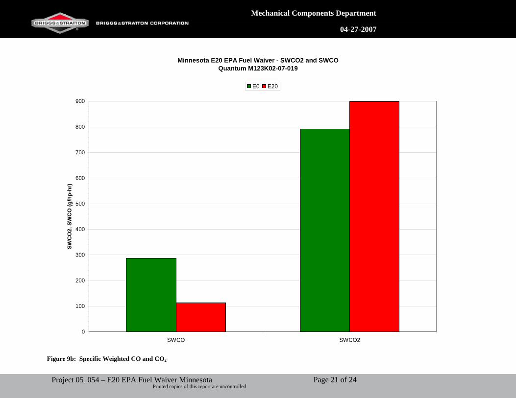
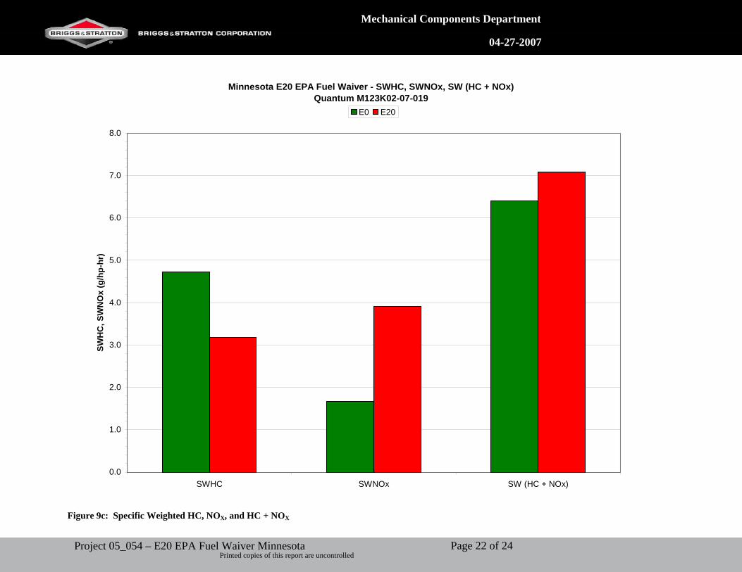
Horsepower and Torque Testing Figure 7 and Figure 8 are horsepower and torque curves, respectively, for each fuel type. A drop in horsepower and torque is observed when operating on E10. This is caused by the reduced energy density of the ethanol in the fuel. A negligible increase in peak horsepower of approximately 2 % is observed with the combustion of E20. Increased evaporative cooling of the intake charge from the extra ethanol provides an increase in power that compensates for the drop in energy density. Also, a negligible change in peak torque was observed. Emissions Exhaust Emissions Standard weighted emissions tests were conducted using a Quantum engine (125K02 – 0500E1 – 05072158). Figure 9a shows the % CO modal data for E0 and E20. Approximately a 3.5 % CO enleanment of E20 vs. E0 was seen at every loading condition. This reduction in CO pushes engine operation to the lean limit. This leads to poor performance for the end-user as previously discussed. Figure 9b shows the specific weighted CO and CO2 emissions. CO2 is not considered a pollutant, but is considered a greenhouse gas and leads to global warming. E20 increased CO2 emissions 107 g/hp-hr, which equates to a 14 % increase. Figure 9c shows the specific weighted HC, NOX, and HC + NOX emissions. Despite the reduction in HC with E20, NOX emissions increased 133%, and therefore resulted in an overall 10.5 % increase in combined HC + NOX emissions. NOX is a smog-forming agent that contributes to the production of acid rain. Table 1 shows the tabulated results from the emissions tests. The results show that a carburetor calibration would be required to maintain current emission levels obtained with E0 and California Phase II Certification fuel. An increase of 10.5 % in weighted HC + NOX was observed when running on E20. The use of E20 in existing engines would require tampering with an emissions control devise in order to maintain HC + NOX levels and thus violate the Federal Clean Air Act. Evaporative Emissions Due to the ethanol in the fuel, the evaporative emissions testing will be conducted at Automotive Testing Labs (ATL).
Page 5 of 24Project 05_054 – E20 EPA Fuel Waiver Minnesota Printed copies of this report are uncontrolled
Mechanical Components Department
04-27-2007
Appendices of Data Material Compatibility Appendix
Figure 1a: New and Dry fuel caps and seals prior to fuel submersion testing
Figure 1b: Fuel cap and seal assembly after a week’s submersion into E20. Notice the bulging of the seal due to the extreme swelling of the gasket seal.
Page 6 of 24Project 05_054 – E20 EPA Fuel Waiver Minnesota Printed copies of this report are uncontrolled
Mechanical Components Department
04-27-2007
Figure 1c: Fuel seal after a week’s submersion into E20. Notice the deformation of the gasket due to the extreme swelling.
Page 7 of 24Project 05_054 – E20 EPA Fuel Waiver Minnesota Printed copies of this report are uncontrolled
Mechanical Components Department
04-27-2007
Figure 2a: Cylinder head exhaust blow-by caused by high combustion temperatures.
Figure 2b: Hot exhaust valve with blow-by caused by high combustion temperatures.
Page 8 of 24Project 05_054 – E20 EPA Fuel Waiver Minnesota Printed copies of this report are uncontrolled
Mechanical Components Department
04-27-2007
Minnesota E20 EPA Fuel Waiver - Exhaust TemperaturesQuantum 123K02-0239E1-04061458
900
950
1000
1050
1100
1150
1200
2000 2200 2400 2600 2800 3000 3200 3400 3600 3800 4000
Engine Speed (RPM)
Tem
pera
ture
(°F)
E0 E10 E20
Figure 3a: Exhaust Temperature Curves
Page 9 of 24Project 05_054 – E20 EPA Fuel Waiver Minnesota Printed copies of this report are uncontrolled
Mechanical Components Department
04-27-2007
Minnesota E20 EPA Fuel Waiver - Spark Plug TemperaturesQuantum 123K02-0239E1-04061458
500
510
520
530
540
550
560
570
580
590
600
2000 2200 2400 2600 2800 3000 3200 3400 3600 3800 4000
Engine Speed (RPM)
Tem
pera
ture
(°F)
E0 E10 E20
Figure 3b: Spark Plug Temperature Curves
Page 10 of 24Project 05_054 – E20 EPA Fuel Waiver Minnesota Printed copies of this report are uncontrolled
Mechanical Components Department
04-27-2007
Minnesota E20 EPA Fuel Waiver - Oil TemperaturesQuantum 123K02-0239E1-04061458
250
275
300
325
350
2000 2200 2400 2600 2800 3000 3200 3400 3600 3800 4000
Engine Speed (RPM)
Tem
pera
ture
(°F)
E0 E10 E20
Figure 3c: Oil Temperature Curves
Page 11 of 24Project 05_054 – E20 EPA Fuel Waiver Minnesota Printed copies of this report are uncontrolled
Mechanical Components Department
04-27-2007
Drivability and Performance Appendix
Minnesota E20 EPA Fuel Waiver - RPM Stability Range (Normalized to E0) @ 40° F
1.00 1.00
1.35
1.03
1.41
1.06
0.00
0.50
1.00
1.50
Blade Bare Shaft
40° F
Test Conditions
RPM
Ran
ge (P
eak
to P
eak)
E0 E10 E20
Figure 4a: RPM peak to peak stability range normalized with respect to E0 @ 40° F
Page 12 of 24Project 05_054 – E20 EPA Fuel Waiver Minnesota Printed copies of this report are uncontrolled
Mechanical Components Department
04-27-2007
Minnesota E20 EPA Fuel Waiver - RPM Stability Range (Normalized to E0) @ 70° F
1.00 1.00
1.11 1.12
1.29
1.20
0.00
0.50
1.00
1.50
Blade Bare Shaft
70° FTest Conditions
RPM
Ran
ge (P
eak
to P
eak)
E0 E10 E20
Figure 4b: RPM peak to peak stability range normalized with respect to E0 @ 70° F
Page 13 of 24Project 05_054 – E20 EPA Fuel Waiver Minnesota Printed copies of this report are uncontrolled
Mechanical Components Department
04-27-2007
Minnesota E20 EPA Fuel Waiver - Blade and Bare Shaft RPM Stability @ 40° F
3000
3500
4000
4500
5000
5500
6000
6500
0 15 30 45 60 75 90 105 120
Time (sec)
RPM
E0 w/ blade 40° E10 w/ blade 40° E20 w/ blade 40° E0 w/ bare shaft 40° E10 w/ bare shaft 40° E20 w/ bare shaft 40°
Actual measurements are offset by 500 rpm to view the data better.
Blade 40° F
Bare Shaft 40° F
Figure 5a: RPM Stability Strip Chart Results @ 40° F
Page 14 of 24Project 05_054 – E20 EPA Fuel Waiver Minnesota Printed copies of this report are uncontrolled
Mechanical Components Department
04-27-2007
Minnesota E20 EPA Fuel Waiver - Blade and Bare Shaft RPM Stability @ 70° F
0
500
1000
1500
2000
2500
3000
3500
0 15 30 45 60 75 90 105 120
Time (sec)
RPM
E0 w/ blade 70° E10 w/ blade 70° E20 w/ blade 70° E0 w/ bare shaft 70° E10 w/ bare shaft 70° E20 w/ bare shaft 70°
Actual measurements are offset by 500 rpm to view the data better. E0 w/ blade at 70° has no offset.
Bare Shaft 70° F
Blade 70° F
Figure 5b: RPM Stability Strip Chart Results @ 70° F
Page 15 of 24Project 05_054 – E20 EPA Fuel Waiver Minnesota Printed copies of this report are uncontrolled

Mechanical Components Department
04-27-2007
Minnesota E20 EPA Fuel Waiver Startability Strip Chart Results @ 40° FQuantum M123K02-07-019
0
1000
2000
3000
4000
5000
6000
7000
8000
9000
0.0 0.5 1.0 1.5 2.0 2.5 3.0
Time (sec)
RPM
E0 w/ blade 40° E10 w/ blade 40° E20 w/ blade 40°
E0 w/ bare shaft 40° E10 w/ bare shaft 40° E20 w/ bare shaft 40°
Actual measurements are offset by 500 rpm to view the data better. E20 bare shaft at 40° has no offset.
Blade 40° F
Bare Shaft 40° F
Figure 6a: Startability Strip Chart Results @ 40°F
Page 16 of 24Project 05_054 – E20 EPA Fuel Waiver Minnesota Printed copies of this report are uncontrolled
Mechanical Components Department
04-27-2007
Minnesota E20 EPA Fuel Waiver Startability Strip Chart Results @ 70° FQuantum M123K02-07-019
0
1000
2000
3000
4000
5000
6000
7000
8000
9000
0.0 0.5 1.0 1.5 2.0 2.5 3.0
Time (sec)
RPM
E0 w/ blade 70° E10 w/ blade 70° E20 w/ blade 70°
E0 w/ bare shaft 70° E10 w/ bare shaft 70° E20 w/ bare shaft 70°
Actual measurements are offset by 500 rpm to view the data better. E20 bare shaft at 70° has no offset.
Blade 70° F
Bare Shaft 70° F
Figure 6b: Startability Strip Chart Results @ 70° F
Page 17 of 24Project 05_054 – E20 EPA Fuel Waiver Minnesota Printed copies of this report are uncontrolled
Mechanical Components Department
04-27-2007
Minnesota E20 EPA Fuel Waiver - Horsepower CurvesQuantum M123K02-07-019
60%
65%
70%
75%
80%
85%
90%
95%
100%
105%
2000 2200 2400 2600 2800 3000 3200 3400 3600 3800 4000
Engine Speed (RPM)
% L
oad
(Nor
mal
ized
to E
0)E0 E10 E20
Figure 7: Horsepower Curves
Page 18 of 24Project 05_054 – E20 EPA Fuel Waiver Minnesota Printed copies of this report are uncontrolled
Mechanical Components Department
04-27-2007
Minnesota E20 EPA Fuel Waiver - Torque CurvesQuantum M123K02-07-019
70%
75%
80%
85%
90%
95%
100%
2000 2200 2400 2600 2800 3000 3200 3400 3600 3800 4000
Engine Speed (RPM)
% T
orqu
e (N
orm
aliz
ed to
E0)
E0 E10 E20
Figure 8: Torque Curves
Page 19 of 24Project 05_054 – E20 EPA Fuel Waiver Minnesota Printed copies of this report are uncontrolled
Mechanical Components Department
04-27-2007
Emissions Appendix
Minnesota E20 EPA Fuel Waiver - Modal % COQuantum M123K02-07-019
0
1
2
3
4
5
6
7
8
10 20 30 40 50 60 70 80 90 100
% Load
% C
O
E0 E20
Figure 9a: % CO vs. % Load
Page 20 of 24Project 05_054 – E20 EPA Fuel Waiver Minnesota Printed copies of this report are uncontrolled
Mechanical Components Department
04-27-2007
Minnesota E20 EPA Fuel Waiver - SWCO2 and SWCOQuantum M123K02-07-019
0
100
200
300
400
500
600
700
800
900
SWCO SWCO2
SWC
O2,
SW
CO
(g/h
p-hr
)
E0 E20
Figure 9b: Specific Weighted CO and CO2
Page 21 of 24Project 05_054 – E20 EPA Fuel Waiver Minnesota Printed copies of this report are uncontrolled
Mechanical Components Department
04-27-2007
Minnesota E20 EPA Fuel Waiver - SWHC, SWNOx, SW (HC + NOx)Quantum M123K02-07-019
0.0
1.0
2.0
3.0
4.0
5.0
6.0
7.0
8.0
SWHC SWNOx SW (HC + NOx)
SWH
C, S
WN
Ox
(g/h
p-hr
)E0 E20
Figure 9c: Specific Weighted HC, NOX, and HC + NOX
Page 22 of 24Project 05_054 – E20 EPA Fuel Waiver Minnesota Printed copies of this report are uncontrolled
Mechanical Components Department
04-27-2007
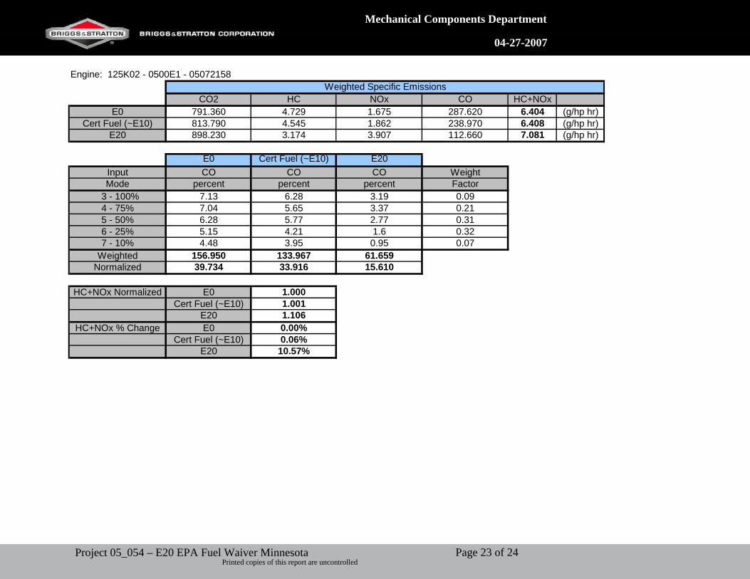
Engine: 125K02 - 0500E1 - 05072158
CO2 HC NOx CO HC+NOxE0 791.360 4.729 1.675 287.620 6.404 (g/hp hr)
Cert Fuel (~E10) 813.790 4.545 1.862 238.970 6.408 (g/hp hr)E20 898.230 3.174 3.907 112.660 7.081 (g/hp hr)
E0 Cert Fuel (~E10) E20Input CO CO CO WeightMode percent percent percent Factor
3 - 100% 7.13 6.28 3.19 0.094 - 75% 7.04 5.65 3.37 0.215 - 50% 6.28 5.77 2.77 0.316 - 25% 5.15 4.21 1.6 0.327 - 10% 4.48 3.95 0.95 0.07
Weighted 156.950 133.967 61.659Normalized 39.734 33.916 15.610
HC+NOx Normalized E0 1.000Cert Fuel (~E10) 1.001
E20 1.106HC+NOx % Change E0 0.00%
Cert Fuel (~E10) 0.06%E20 10.57%
Weighted Specific Emissions
Page 23 of 24Project 05_054 – E20 EPA Fuel Waiver Minnesota Printed copies of this report are uncontrolled
Mechanical Components Department
04-27-2007
CUSTOMER PO NO. SALES ORDER NO. MFG DATE: 12-2004 SHELF LIFE: UNDETERMINED
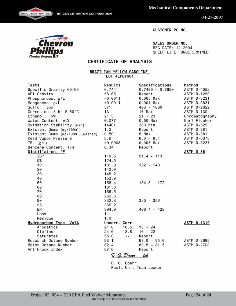
CERTIFICATE OF ANALYSIS
BRAZILIAN YELLOW GASOLINE LOT 4LPBYG01
Tests Results Specifications MethodSpecific Gravity 60/60 0.7441 0.7400 – 0.7650 ASTM D-4052 API Gravity 58.65 Report ASTM D-1250 Phosphorous, g/L <0.0011 0.005 Max ASTM D-3231 Manganese, g/L <0.0011 0.001 Max ASTM D-3831 Sulfur, ppm 571 400 - 1000 ASTM D-2622 Corrosion, 3 hr @ 50°C 1A 1B Max ASTM D-130 Ethanol, lv% 21.5 21 - 23 Chromatography Water Content, wt% 0.077 0.50 Max Karl Fischer Oxidation Stability (min) 1440+ 360 Min ASTM D-525 Existent Gums (mg/100ml) 1.2 Report ASTM D-381 Existent Gums (mg/100ml)(washed) 0.50 5 Max ASTM D-381 Reid Vapor Pressure 8.6 8.0 – 9.4 ASTM D-6378 TEL (g/L) <0.0008 0.005 Max ASTM D-3237 Benzene Content, lv% 0.34 Report Distillation, °F ASTM D-86 IBP 110.5 91.4 - 113 5% 124.5 10 131.9 122 - 140 20 142.9 30 145.2 40 153.9 50 158.4 154.5 - 172 60 161.6 70 166.5 80 262.6 90 332.8 320 - 356 95 365.2 EP 394.9 406.4 - 428 Loss 1.1 Residue 1.0 Hydrocarbon Type, Vol% Uncorr. Corr. ASTM D-1319 Aromatics 21.0 16.5 16 - 24 Olefins 24.0 18.8 16 - 22 Saturates 55.0 -- Report Research Octane Number 93.1 93.0 – 95.0 ASTM D-2699 Motor Octane Number 82.4 80.5 – 81.5 ASTM D-2700 Antiknock Index 87.8 Report
D. G. Doerr Fuels Unit Team Leader
Page 24 of 24Project 05_054 – E20 EPA Fuel Waiver Minnesota Printed copies of this report are uncontrolled

1
EXHIBIT D
2
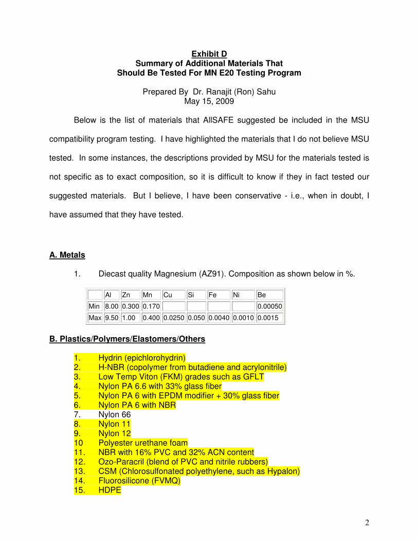
Exhibit D
Summary of Additional Materials That
Should Be Tested For MN E20 Testing Program
Prepared By Dr. Ranajit (Ron) Sahu
May 15, 2009
Below is the list of materials that AllSAFE suggested be included in the MSU
compatibility program testing. I have highlighted the materials that I do not believe MSU
tested. In some instances, the descriptions provided by MSU for the materials tested is
not specific as to exact composition, so it is difficult to know if they in fact tested our
suggested materials. But I believe, I have been conservative - i.e., when in doubt, I
have assumed that they have tested.
A. Metals
1. Diecast quality Magnesium (AZ91). Composition as shown below in %.
Al Zn Mn Cu Si Fe Ni Be
Min 8.00 0.300 0.170 0.00050
Max 9.50 1.00 0.400 0.0250 0.050 0.0040 0.0010 0.0015
B. Plastics/Polymers/Elastomers/Others
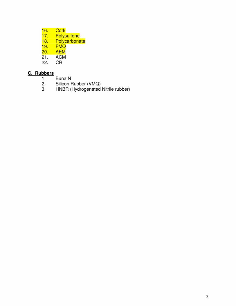
1. Hydrin (epichlorohydrin) 2. H-NBR (copolymer from butadiene and acrylonitrile) 3. Low Temp Viton (FKM) grades such as GFLT 4. Nylon PA 6.6 with 33% glass fiber 5. Nylon PA 6 with EPDM modifier + 30% glass fiber 6. Nylon PA 6 with NBR 7. Nylon 66 8. Nylon 11 9. Nylon 12 10 Polyester urethane foam 11. NBR with 16% PVC and 32% ACN content 12. Ozo-Paracril (blend of PVC and nitrile rubbers) 13. CSM (Chlorosulfonated polyethylene, such as Hypalon) 14. Fluorosilicone (FVMQ) 15. HDPE
3
16. Cork 17. Polysulfone 18. Polycarbonate 19. FMQ 20. AEM 21. ACM 22. CR
C. Rubbers
1. Buna N 2. Silicon Rubber (VMQ) 3. HNBR (Hydrogenated Nitrile rubber)

EXHIBIT E
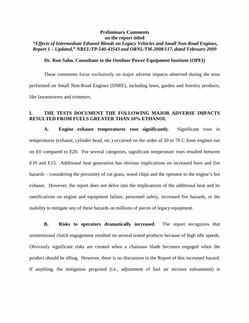
Preliminary Comments on the report titled
“ Effects of Intermediate Ethanol Blends on Legacy Vehicles and Small Non-Road Engines, Report 1 – Updated,” NREL/TP-540-43543 and ORNL/TM-2008/117, dated February 2009
Dr. Ron Sahu, Consultant to the Outdoor Power Equipment Institute (OPEI)
These comments focus exclusively on major adverse impacts observed during the tests
performed on Small Non-Road Engines (SNRE), including lawn, garden and forestry products,
like lawnmowers and trimmers.
I. THE TESTS DOCUMENT THE FOLLOWING MAJOR ADVERSE IMPACTS RESULTED FROM FUELS GREATER THAN 10% ETHANOL
A. Engine exhaust temperatures rose significantly. Significant rises in
temperatures (exhaust, cylinder head, etc.) occurred on the order of 20 to 70 C from engines run
on E0 compared to E20. For several categories, significant temperature rises resulted between
E10 and E15. Additional heat generation has obvious implications on increased burn and fire
hazards – considering the proximity of cut grass, wood chips and the operator to the engine’s hot
exhaust. However, the report does not delve into the implications of the additional heat and its
ramifications on engine and equipment failure, personnel safety, increased fire hazards, or the
inability to mitigate any of these hazards on millions of pieces of legacy equipment.
B. Risks to operators dramatically increased. The report recognizes that
unintentional clutch engagement resulted on several tested products because of high idle speeds.
Obviously significant risks are created when a chainsaw blade becomes engaged when the
product should be idling. However, there is no discussion in the Report of this increased hazard.
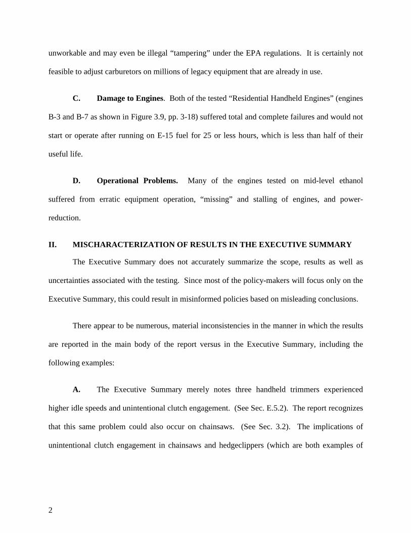
If anything, the mitigation proposed (i.e., adjustment of fuel air mixture enleanment) is
2
unworkable and may even be illegal “ tampering” under the EPA regulations. It is certainly not
feasible to adjust carburetors on millions of legacy equipment that are already in use.
C. Damage to Engines. Both of the tested “Residential Handheld Engines” (engines
B-3 and B-7 as shown in Figure 3.9, pp. 3-18) suffered total and complete failures and would not
start or operate after running on E-15 fuel for 25 or less hours, which is less than half of their
useful life.
D. Operational Problems. Many of the engines tested on mid-level ethanol
suffered from erratic equipment operation, “missing” and stalling of engines, and power-
reduction.
II. MISCHARACTERIZATION OF RESULTS IN THE EXECUTIVE SUMMARY
The Executive Summary does not accurately summarize the scope, results as well as
uncertainties associated with the testing. Since most of the policy-makers will focus only on the
Executive Summary, this could result in misinformed policies based on misleading conclusions.
There appear to be numerous, material inconsistencies in the manner in which the results
are reported in the main body of the report versus in the Executive Summary, including the
following examples:
A. The Executive Summary merely notes three handheld trimmers experienced
higher idle speeds and unintentional clutch engagement. (See Sec. E.5.2). The report recognizes
that this same problem could also occur on chainsaws. (See Sec. 3.2). The implications of
unintentional clutch engagement in chainsaws and hedgeclippers (which are both examples of
3
close-to-the-body, sharp-bladed equipment) are obvious and alarming; this substantial problem
should have been fully addressed in the Executive Summary.
B. With regards to materials compatibility, the Executive Summary incorrectly
concludes that “…no obvious materials compatibility issues were noted…” (see p. xix). In fact,
the report itself recognizes that materials incompatibility (such as swelling of the elastomeric
seat for the needle in the carburetor bowl) could be the cause of the engine stall for the Briggs
and Stratton generator observed in the pilot study (see pp. 3-15). The report also states that: 1)
“…various fuel-wetted materials in some small engines may not be compatible with all ethanol
blends…” (see p. 3-9); and 2) “ ..materials compatibility issues…were not specifically
characterized as part of the study…” (see p. 3-12).
C. Engines in the study experienced “unstable governor operation,” “missing” and
“stalling” when operating on E20 fuel, indicating unacceptable performance. (See Section
3.2.2). However, the Executive Summary omitted any discussion of these substantial problems.
D. Discussing emissions, the Executive Summary simply notes that HC emissions
“generally decreased” and that combined HC+NOx emissions “decreased in most instances.”
(See p. xix). However, the report notes that while HC emissions generally decreased, they also
increased in some engines. The net change in HC+NOx emissions ranged from -36% to +41%
as reported in Sec. 3.2.2. It is important to note that for new engines, the net change in HC+NOx
was often greatest in going from E0 to E10 and smaller in the other transitions (i.e., from E0 to
E15 or E0 to E20). (See Table 3.7). For example, the numerical average for all engines shows
that the HC+NOx reduction was -16.6% from E0 to E10; -13.5% from E0 to E15 and only -9.5%
from E0 to E20. Since small engines are already capable of E10 operation and that fuel is
4
already available, this data indicates that transitioning to E15 and E20 may actually increase
HC+NOx from E10. (As a side note, what is actually measured as HC in the study is unclear
since a FID was used for this purpose, uncorrected for any ethanol or aldehydes, as noted in the
report).
III. DEFICIENCIES IN THE TESTING PLAN AND SCOPE
A. No emissions testing pertaining to evaporative emissions was conducted. Thus,
all references to “emissions” means tail-pipe emissions from the engine. Evaporative emissions
are now regulated by EPA for small engines and equipment and covered by the EPA
“certification” program. Lack of evaporative emissions is a major omission.
B. The report does not contain any direct data on “materials compatibility” testing or
results – i.e., involving the various fuels tested and the materials that may be exposed to these
fuels and how they interact. Material compatibility is a significant concern with E15 and E20
fuels when used in small engines, leading not only to “operational issues” but also to durability,
emissions, and safety impacts.
C. The report notes that the following fuels were used: E0, as well as splash-blended
E10, E15, and E20. However, the report does not contain the actual ASTM specification of the
blended fuels, including all relevant properties such as distillation cut point temperatures, etc.
Table 2.2 of the report contains a few parameters of the blends. This is incomplete and a more
compete fuel specification should be provided. The executive summary concludes that “…the
different fuel characteristics of match-blended and splash-blended fuels were not expected to
have a significant impact on temperature” or on durability. (See p. xviii). However, there is not
any cited technical support for these statements. Similarly, there is no support for the
5
observation that “…emission results…are not expected to vary significantly…between splash-
blended and match-blended fuels.” Id.
D. As the report notes, neither cold-start, nor warm-up testing was done, although
these are two very common modes of operation for many categories of small engines.
Additional performance tests that impact “operational issues” which should have been tested
include: (i) acceleration; (ii) application performance; (iii) carburetor and breather icing; (iv) fuel
consumption; (v) governor stability; (vi) load pick up; and (vii) vapor lock. Individual categories
of small engines will likely have additional performance-related test requirements.
E. As the Executive Summary notes, the report presents “ initial results…focused on
identifying emissions or operational issues and measurement of several key engine
temperatures…” (See p. xviii). It is not clear what is meant by “operational issues” or what
quantitative surrogates and/or metrics were used to substitute for operational issues. It appears
that erratic operation, high idle, stalling, etc. were used as evidence of operational issues. While
these are undeniably evidence of operational issues, no testing appears to have been done on
various actual equipment operational modes (as discussed later) so the full extent of operational
issues has by no means been evaluated.
F. The report does not fully flesh out the issue and implications of irreversibility –
i.e., once exposed to E15 and/or E20, performance is not restored simply by reverting to E0. In
the case of the Poulan weedeater, it is noted that there were poor operations with E15 and E20
and that “normal operation could not be restored on E0.” (See Section 3.2.2). This is significant.
Actual users, when faced with operational problems with ethanol blended fuels, will, as common
6
sense dictates, revert to E0. What they will find is that doing so will not “unring the bell” since
the damage by the ethanol blends is not reversible simply by changing the fuel.
IV. UNREPRESENTATIVE AND LIMITED NUMBER OF TESTS CONDUCTED
A. The category of forestry, lawn and garden equipment includes a broad swath of
equipment and engine types. Yet, the category has not been defined in the report so that the
extent of test results presented can be judged in context. While noting that millions of products
with small engines are sold each year (actually tens of millions), and that EPA certifies on the
order of 900 engine emission families, the report does not cover the immense diversity of the
category including: 1) the various engine and equipment types used, 2) the fuel delivery
mechanisms, 3) the various sizes and functions of the equipment, 4) the constraints that the
equipment operate under (such as close proximity to operators, as an example), and 5) many
other characteristics. Engines in this product category utilize a wide variety of engine
architecture including both single and twin cylinders, two cycle and four cycle combustion,
ported and valve charge controlled, side valve and overhead valve orientations, with and without
exhaust after-treatment, governed load and product load controlled, etc. The report should
clearly qualify its findings are based on a tiny fraction of the diverse population of affected
products.
B. The types and numbers of engines and equipment tested are inadequate to be
representative of even the limited types of small engines that were the subject of testing. While
practical constraints such as time and money will always constrain the amount of testing that can
be done, the basis for choosing the engine and equipment – namely those found in “…popular,
high sales volume equipment…” appears not to have been followed. For example, of the six
pieces of equipment selected for the pilot study, four were generators. No chainsaws were
7
tested, even though the OPEI had directly requested that they be included – because of their
extreme operating conditions and sensitivity to mid-level ethanol. Also, it is explicable why only
one residential hand-held engine would be tested, even though these are likely to be very
sensitive to fuel changes. The report should provide the basis of selection rather than referencing
unspecified EPA sources. One of the constraints also seems to have been the available
laboratory equipment (i.e., lack of small engine dynamometers). This is clearly an inappropriate
basis for constraining equipment selection, especially if the goal is to obtain data on the entire
class of affected engines and products.
C. The report rightly notes the challenges associated with multi-cylinder engines –
although characterizing these as being “more sensitive” is too vague. (See p. 3-11). It is
unfortunate that while the study included one twin cylinder engine in the initial screening
process, there were no twin cylinder engines included in the more in depth portions of the testing
program. Particularly when the initial screening test clearly demonstrated significant influences
of higher ethanol blends. A significant portion of the Class 2 (>225 cc) non-handheld engines
produced each year are two cylinder engines. The omission of these engines in the expanded
program is puzzling. The detailed test program should include engines and equipment that
demonstrated any significant influence during the screening tests.
D. The limited number of tests conducted cannot provide assurances that the results
presented have any statistical significance, where appropriate. In fact, no attempt is made to
discuss results in terms of statistical significance. Nor are such issues discussed in support of the
design of the test matrix itself. For example, no pair-wise tests were run or results reported even
though those opportunities were available even with the limited equipment selection.
8
E. The manner in which the tests were run makes it difficult to separate the effects of
engines, fuels, and aging. For example, the full-life tests do not allow the ability to distinguish
between fuel-driven and engine-driven causes since only one engine was tested on each fuel. In
the pilot study, the effects of the fuel and aging are similarly hard to separate. These types of
issues could have been avoided with better test planning.
V. OTHER COMMENTS
A. The comments are preliminary because not all of the test data discussed in the
report are included. Specifically, backup test data for all tests conducted by the Dept. of Energy
(NREL and ORNL) and its contractors (TRC) still need to be provided.
B. The report notes that the test plan was developed with close consultation
involving, among others, “…US automobile companies, engine companies, and other
organizations…” It would be helpful to have details of all the companies and individuals
consulted in an Appendix to the report.
C. The report does not separately discuss the comments of the peer reviewer(s) and
what changes were made to the draft report as a result. While the Acknowledgements note that
the peer review panel was led by Joseph Colucci, the report does not contain a list of all peer
reviewers used, what portions of the report were peer reviewed by whom, and the necessary vitae
for the reviewers. This should be included.
DC01/SAHUD/360000.12
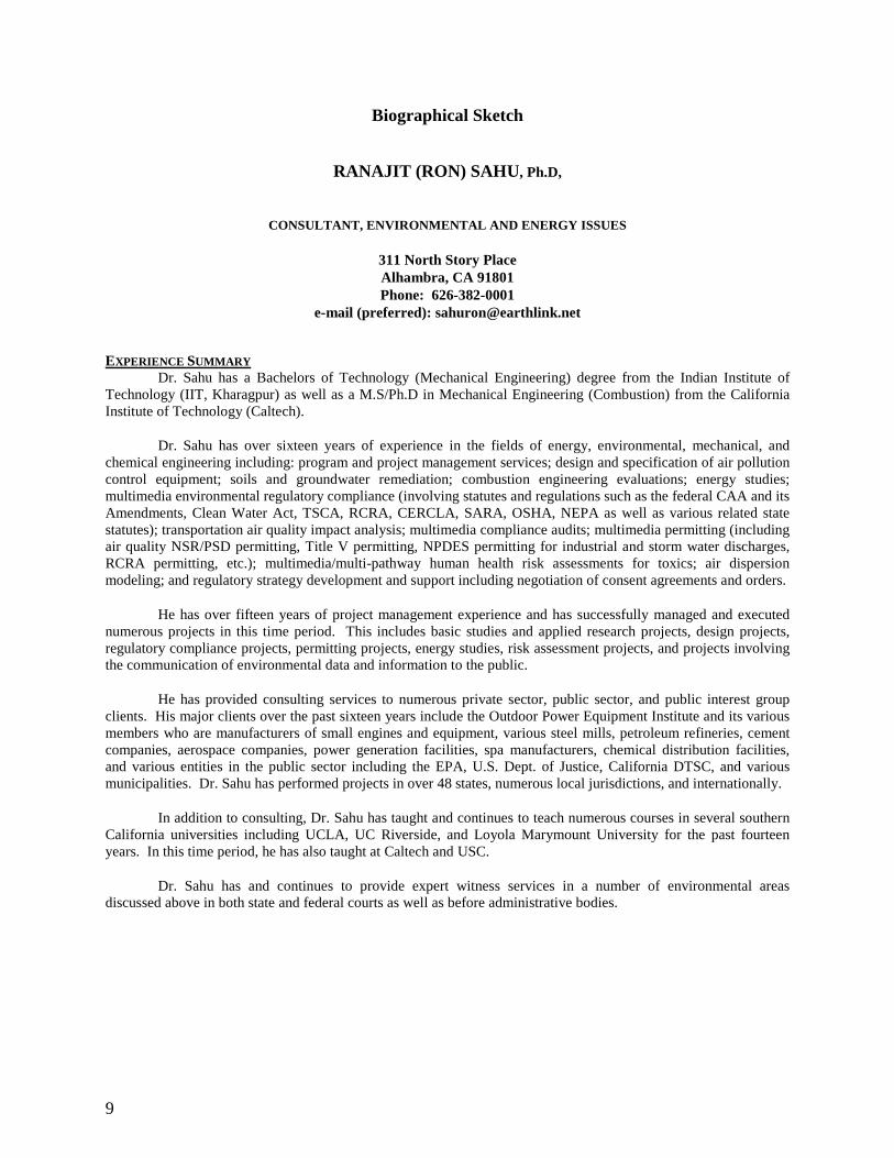
9
Biographical Sketch
RANAJIT (RON) SAHU, Ph.D,
CONSULTANT, ENVIRONMENTAL AND ENERGY ISSUES
311 North Story Place Alhambra, CA 91801 Phone: 626-382-0001
e-mail (preferred): [email protected]
EXPERIENCE SUMMARY Dr. Sahu has a Bachelors of Technology (Mechanical Engineering) degree from the Indian Institute of
Technology (IIT, Kharagpur) as well as a M.S/Ph.D in Mechanical Engineering (Combustion) from the California Institute of Technology (Caltech).
Dr. Sahu has over sixteen years of experience in the fields of energy, environmental, mechanical, and chemical engineering including: program and project management services; design and specification of air pollution control equipment; soils and groundwater remediation; combustion engineering evaluations; energy studies; multimedia environmental regulatory compliance (involving statutes and regulations such as the federal CAA and its Amendments, Clean Water Act, TSCA, RCRA, CERCLA, SARA, OSHA, NEPA as well as various related state statutes); transportation air quality impact analysis; multimedia compliance audits; multimedia permitting (including air quality NSR/PSD permitting, Title V permitting, NPDES permitting for industrial and storm water discharges, RCRA permitting, etc.); multimedia/multi-pathway human health risk assessments for toxics; air dispersion modeling; and regulatory strategy development and support including negotiation of consent agreements and orders.
He has over fifteen years of project management experience and has successfully managed and executed numerous projects in this time period. This includes basic studies and applied research projects, design projects, regulatory compliance projects, permitting projects, energy studies, risk assessment projects, and projects involving the communication of environmental data and information to the public.
He has provided consulting services to numerous private sector, public sector, and public interest group clients. His major clients over the past sixteen years include the Outdoor Power Equipment Institute and its various members who are manufacturers of small engines and equipment, various steel mills, petroleum refineries, cement companies, aerospace companies, power generation facilities, spa manufacturers, chemical distribution facilities, and various entities in the public sector including the EPA, U.S. Dept. of Justice, California DTSC, and various municipalities. Dr. Sahu has performed projects in over 48 states, numerous local jurisdictions, and internationally.
In addition to consulting, Dr. Sahu has taught and continues to teach numerous courses in several southern California universities including UCLA, UC Riverside, and Loyola Marymount University for the past fourteen years. In this time period, he has also taught at Caltech and USC.
Dr. Sahu has and continues to provide expert witness services in a number of environmental areas discussed above in both state and federal courts as well as before administrative bodies.

EXHIBIT F
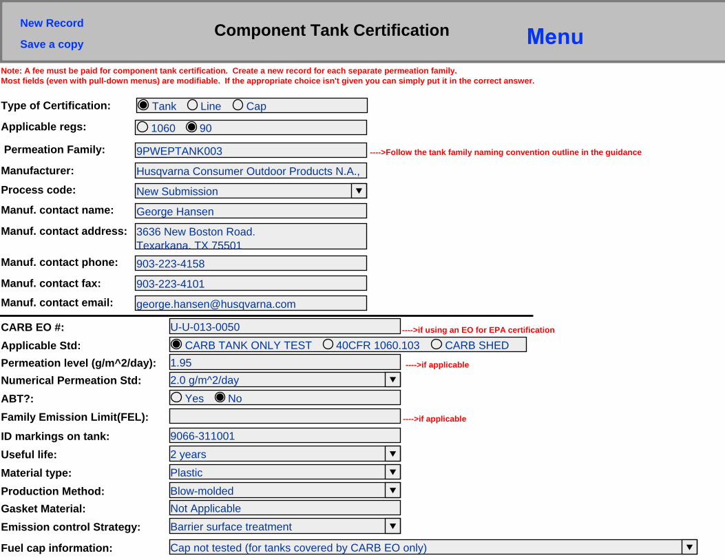
Component Tank Certification
9PWEPTANK003
Tank Line CapType of Certification:
Permeation Family: ---->Follow the tank family naming convention outline in the guidance
New Submission
Husqvarna Consumer Outdoor Products N.A.,Manufacturer:
Process code:
George HansenManuf. contact name:
903-223-4158
3636 New Boston Road.Texarkana, TX 75501
Manuf. contact address:
Manuf. contact phone:
903-223-4101Manuf. contact fax:
Manuf. contact email:
U-U-013-0050CARB EO #:
1.95Permeation level (g/m^2/day):2.0 g/m^2/dayNumerical Permeation Std:
---->if using an EO for EPA certification
Note: A fee must be paid for component tank certification. Create a new record for each separate permeation family.Most fields (even with pull-down menus) are modifiable. If the appropriate choice isn't given you can simply put it in the correct answer.
CARB TANK ONLY TEST 40CFR 1060.103 CARB SHEDApplicable Std:
9066-311001ID markings on tank:2 yearsUseful life:PlasticMaterial type:Blow-moldedProduction Method:Not ApplicableGasket Material:Barrier surface treatmentEmission control Strategy:
Yes NoABT?:Family Emission Limit(FEL): ---->if applicable
1060 90Applicable regs:
New Record
Cap not tested (for tanks covered by CARB EO only)Fuel cap information:
Save a copy
---->if applicable
CARB EO U-U-013-0050 is used for Fuel Tanks used on following engine families:9PWES.0354CJ9PWES.0404CK
u-u-013-0050.pdf
Comments:
Container Field 1:Files such as word documents, PDFs, and Excel documents can be placed in container fields. The CARB EO or a list of engine families which utilize this component, can be placed in the
Container Field 2:
---->Integratedthe engine fain the comme
Fuel cap FEL: ---->if applicable
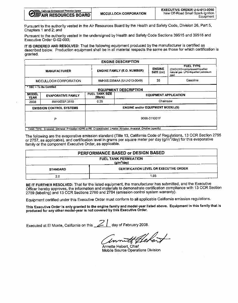

EXHIBIT G
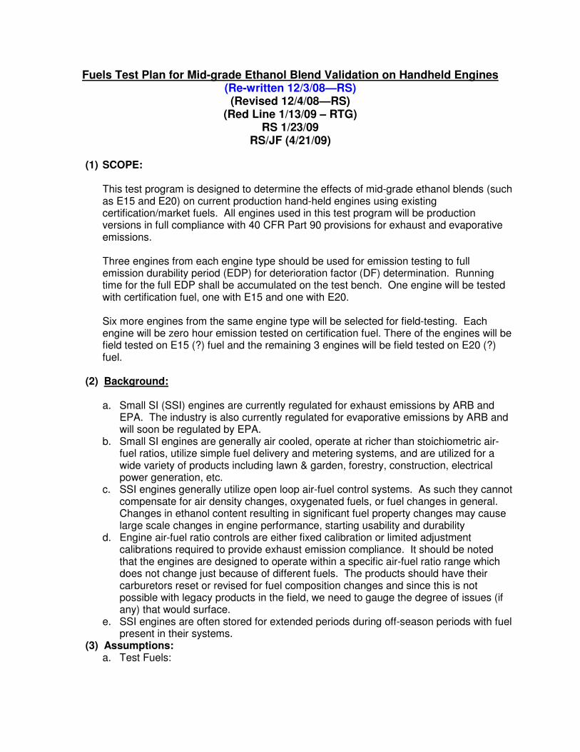
Fuels Test Plan for Mid-grade Ethanol Blend Validation on Handheld Engines
(Re-written 12/3/08—RS)
(Revised 12/4/08—RS)
(Red Line 1/13/09 – RTG)
RS 1/23/09
RS/JF (4/21/09)
(1) SCOPE:
This test program is designed to determine the effects of mid-grade ethanol blends (such as E15 and E20) on current production hand-held engines using existing certification/market fuels. All engines used in this test program will be production versions in full compliance with 40 CFR Part 90 provisions for exhaust and evaporative emissions.
Three engines from each engine type should be used for emission testing to full emission durability period (EDP) for deterioration factor (DF) determination. Running time for the full EDP shall be accumulated on the test bench. One engine will be tested with certification fuel, one with E15 and one with E20. Six more engines from the same engine type will be selected for field-testing. Each engine will be zero hour emission tested on certification fuel. There of the engines will be field tested on E15 (?) fuel and the remaining 3 engines will be field tested on E20 (?) fuel.
(2) Background:
a. Small SI (SSI) engines are currently regulated for exhaust emissions by ARB and
EPA. The industry is also currently regulated for evaporative emissions by ARB and will soon be regulated by EPA.
b. Small SI engines are generally air cooled, operate at richer than stoichiometric air-fuel ratios, utilize simple fuel delivery and metering systems, and are utilized for a wide variety of products including lawn & garden, forestry, construction, electrical power generation, etc.
c. SSI engines generally utilize open loop air-fuel control systems. As such they cannot compensate for air density changes, oxygenated fuels, or fuel changes in general. Changes in ethanol content resulting in significant fuel property changes may cause large scale changes in engine performance, starting usability and durability
d. Engine air-fuel ratio controls are either fixed calibration or limited adjustment calibrations required to provide exhaust emission compliance. It should be noted that the engines are designed to operate within a specific air-fuel ratio range which does not change just because of different fuels. The products should have their carburetors reset or revised for fuel composition changes and since this is not possible with legacy products in the field, we need to gauge the degree of issues (if any) that would surface.
e. SSI engines are often stored for extended periods during off-season periods with fuel present in their systems.
(3) Assumptions:
a. Test Fuels:
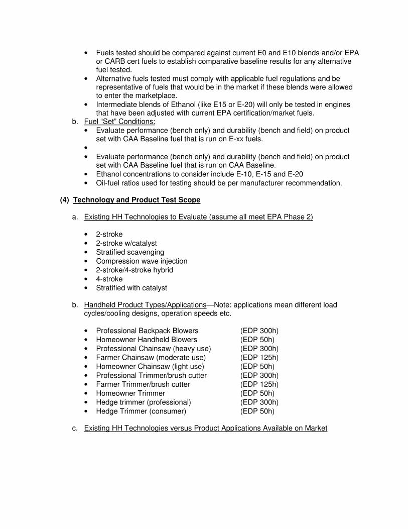
• Fuels tested should be compared against current E0 and E10 blends and/or EPA or CARB cert fuels to establish comparative baseline results for any alternative fuel tested.
• Alternative fuels tested must comply with applicable fuel regulations and be representative of fuels that would be in the market if these blends were allowed to enter the marketplace.
• Intermediate blends of Ethanol (like E15 or E-20) will only be tested in engines that have been adjusted with current EPA certification/market fuels.
b. Fuel “Set” Conditions:
• Evaluate performance (bench only) and durability (bench and field) on product set with CAA Baseline fuel that is run on E-xx fuels.
•
• Evaluate performance (bench only) and durability (bench and field) on product set with CAA Baseline fuel that is run on CAA Baseline.
• Ethanol concentrations to consider include E-10, E-15 and E-20
• Oil-fuel ratios used for testing should be per manufacturer recommendation.
(4) Technology and Product Test Scope
a. Existing HH Technologies to Evaluate (assume all meet EPA Phase 2)
• 2-stroke
• 2-stroke w/catalyst
• Stratified scavenging
• Compression wave injection
• 2-stroke/4-stroke hybrid
• 4-stroke
• Stratified with catalyst
b. Handheld Product Types/Applications—Note: applications mean different load cycles/cooling designs, operation speeds etc.
• Professional Backpack Blowers (EDP 300h)
• Homeowner Handheld Blowers (EDP 50h)
• Professional Chainsaw (heavy use) (EDP 300h)
• Farmer Chainsaw (moderate use) (EDP 125h)
• Homeowner Chainsaw (light use) (EDP 50h)
• Professional Trimmer/brush cutter (EDP 300h)
• Farmer Trimmer/brush cutter (EDP 125h)
• Homeowner Trimmer (EDP 50h)
• Hedge trimmer (professional) (EDP 300h)
• Hedge Trimmer (consumer) (EDP 50h)
c. Existing HH Technologies versus Product Applications Available on Market
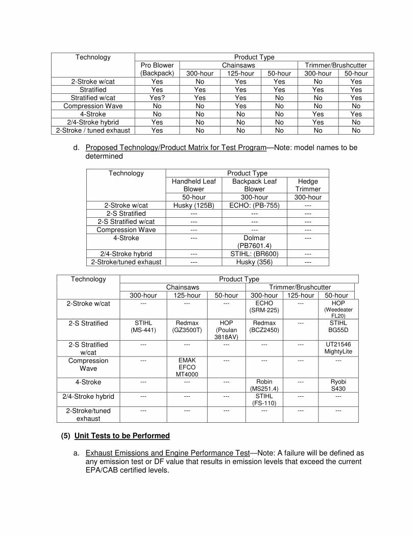
d. Proposed Technology/Product Matrix for Test Program—Note: model names to be
determined
Product Type
Handheld Leaf Blower
Backpack Leaf Blower
Hedge Trimmer
Technology
50-hour 300-hour 300-hour
2-Stroke w/cat Husky (125B) ECHO: (PB-755) ---
2-S Stratified --- --- ---
2-S Stratified w/cat --- --- ---
Compression Wave --- --- ---
4-Stroke --- Dolmar (PB7601.4)
---
2/4-Stroke hybrid --- STIHL: (BR600) ---
2-Stroke/tuned exhaust --- Husky (356) ---
Product Type
Chainsaws Trimmer/Brushcutter
Technology
300-hour 125-hour 50-hour 300-hour 125-hour 50-hour
2-Stroke w/cat --- --- --- ECHO (SRM-225)
--- HOP (Weedeater
FL20)
2-S Stratified STIHL (MS-441)
Redmax (GZ3500T)
HOP (Poulan 3818AV)
Redmax (BCZ2450)
--- STIHL BG55D
2-S Stratified w/cat
--- --- --- --- --- UT21546 MightyLite
Compression Wave
--- EMAK EFCO
MT4000
--- --- --- ---
4-Stroke --- --- --- Robin (MS251.4)
--- Ryobi S430
2/4-Stroke hybrid --- --- --- STIHL (FS-110)
--- ---
2-Stroke/tuned exhaust
--- --- --- --- --- ---
(5) Unit Tests to be Performed
a. Exhaust Emissions and Engine Performance Test—Note: A failure will be defined as
any emission test or DF value that results in emission levels that exceed the current EPA/CAB certified levels.
Product Type
Chainsaws Trimmer/Brushcutter
Technology
Pro Blower (Backpack) 300-hour 125-hour 50-hour 300-hour 50-hour
2-Stroke w/cat Yes No Yes Yes No Yes
Stratified Yes Yes Yes Yes Yes Yes
Stratified w/cat Yes? Yes Yes No No Yes
Compression Wave No No Yes No No No
4-Stroke No No No No Yes Yes
2/4-Stroke hybrid Yes No No No Yes No
2-Stroke / tuned exhaust Yes No No No No No
• With the exception of the test fuel all tests are conducted following the requirements of 40 CFR Part 90.
• All tests shall be run with the carburetor set to the manufacturer’s recommended setting
• Randomly select 3 engines for the engine type and tag each engine according to type of fuel to be used for testing; “1” for certification fuel testing, “2” for E15 fuel testing and “3” for E20 fuel testing.
• Standard engine/product set-up and break-in procedures must be used as defined by the manufacturer.
• Any operational and performance issues throughout the test shall be noted.
• Performance with E15 and E20 shall be compared to the baseline engine tested on certification fuel.
• Report the test information required by the EPA for certification (see sample EPA test data sheet in Appendix “B”) as well as a statistical comparison of the different fuels and their effects (if any).
b. Conduct the exhaust gas and surface temperature test using SAE J335. Report
results according to SAE J335—A failure is deemed to be results outside SAE limits for mulitposition products.
c. Starting/Acceleration/RPM Stability Performance Tests (data sheet in Appendix
“A”)—A failure should be defined as a unit that stalls, a unit that has an idle speed increase to unsafe limits, or a unit that will not start at cold temps.
• Fill product with test fuel and store in test ambient environment for 4-hours.
• Open fuel cap for 30-seconds and then re-install the fuel cap.
• Follow manufacturer recommended starting procedure. Record the number of fuel purges, choke on pulls, partial choke on pulls (if applicable) and choke off pulls. Record the throttle position during starting. Record the product’s specified clutch engagement speed.
• Immediately perform rpm, acceleration and rollout test following the sequence in the data sheet included in Appendix A.
• Record the humidity and ambient temperature at the beginning and end of each test on each unit.
• Repeat test three times on three production samples at each of the specified test ambients.
• Test ambient (+/-5 °F): I. Cold Ambient (-30 °F for saws and 25 °F for others) II. Hot ambient for all products (100-110 °F)
III. Normal (70 °F)
d. Durability/Deterioration Accumulation (bench and field Testing)—RS comment—need to mention field and bench test procedure and data sheets
• Bench Testing Procedure I. Three engines shall be used for this test. For each fuel type (Current cert
fuel, E-15 and E-20). All engines shall be adjusted using the baseline (current) EPA test fuel. Each product shall then be designated for use with one of the test fuels.
II. The engines shall be run-in (break-in) according to the manufacturers recommendation on the bench. The manufacturer’s standardized test fixturing shall be used. The break-in time shall be according to the manufacturer’s recommendations. The break-in shall be recorded using a data sheet similar to that in Appendix “D”.
III. The “zero hour” emission and performance test shall be conducted (see Section (4)a above. As an option, the emission/performance test may be run on each of the test fuels for each product.
IV. Durability time shall be accumulated for one half the product’s designated EDP on the units with each applicable test fuel using the manufacturer’s recommended bench test set-up. The time shall be accumulated using the appropriate CARB WOT-Idle cycle for emission test durability accumulation time. Maintenance on the engine may be performed during this time according to the manufacturer’s recommendations spelled out in the product Operator’s Manual. An incidence log shall be kept documenting the accumulated time.
V. The “mid-point” emission and performance test shall be conducted (see Section (4)a above. As an option, the emission/performance test may be run on each of the test fuels for each product. If maintenance is required, it shall be performed after the initial test. A second emission test may be performed after the maintenance and the average of these two tests used in the DF calculation below.
VI. Durability time shall be accumulated for the rest of the product’s designated EDP on the units with the assigned test fuel using the manufacturer’s recommended bench test set-up. The time shall be accumulated using the appropriate CARB WOT-Idle cycle for emission test durability accumulation time. Maintenance on the engine may be performed during this time according to the manufacturer’s recommendations spelled out in the product Operator’s Manual. An incidence log shall be kept documenting the accumulated time.
VII. The “ending” emission and performance test shall be conducted (see Section (4)a above. As an option, the emission/performance test may be run on each of the test fuels for each product. If maintenance is required, it shall be performed after the initial test. A second emission test may be performed after the maintenance and the average of these two tests used in the DF calculation below.
VIII. The deterioration value for emission shall be determined for each engine/fuel type tested following normally accepted CARB/EPA calculation procedures.
IX. The manufacturer of the product shall perform an engine teardown inspection for each engine. Specific documentation and reporting (including pass-fail criteria) shall include: i. Crankshaft assembly (bearings etc) ii. Cylinder/piston (varnish, finish, port clogging, deposits etc iii. Carburetor and other fuel system components iv. Other (per manufacturer)
• Field Test Procedure—Note: every effort should be made to accumulate field durability time in a manner consistent with real world conditions. This may be done using professional crews, homeowners or manufacturer crews. The users should be allowed to use the product without outside influence by the
manufacturer or other interested parties. This would include their normal usage and maintenance patterns. Instruction on the use and care of the product can be provided to the users by the manufacturer at the beginning of the program using only that information provided in the users manual.
I. Three products of the same engine type shall be selected for the test. Each
product shall be adjusted using the manufacturer’s current procedures and fuel. Each product shall then be designated for use with only one specific test fuel. The manufacturer may break-in the engine and run an emission/performance test prior to the field test program start. The manufacturer may run this test on all of the test fuels if they desire.
II. Product users shall be pre-selected and screened for their willingness to accumulate durability time on the product and complete a basic weekly log sheet (see Appendix “E)”. Each approved user shall be assigned a product, be provided with a sufficient amount of fuel (need to determine if all fuel is supplied at one time or if weekly/monthly increments are given). The user shall be instructed on safe use and care of the product per the user’s manual. The user shall be provided with any necessary safety gear, tools and oil for the test.
III. The manufacturer shall monitor the test product through the submission of weekly test log sheets. Once the product has reached its designated EDP, it shall be removed from test.
X. The “ending” emission and performance test shall be conducted (see Section (4) above. As an option, the emission/performance test may be run on each of the test fuels for each product. If maintenance is required, it shall be performed after the initial test. A second emission test may be performed after the maintenance and the average of these two tests used in the DF calculation below.
XI. The deterioration value for emission shall be determined for each engine/fuel type tested following normally accepted CARB/EPA calculation procedures.
XII. The manufacturer of the product shall perform an engine teardown inspection for each engine. Specific documentation and reporting (including pass-fail criteria) shall include: i. Crankshaft assembly (bearings etc) ii. Cylinder/piston (varnish, finish, port clogging, deposits etc iii. Carburetor and other fuel system components iv. Other (per manufacturer)
(6) Fuel System Component Tests to be Performed
a. Component tests (material compatibility)—Failure of components (in terms of
material physical properties) is to be determined.
Note: Test both short term and long-term exposure of fuel system materials with proposed ethanol blends to determine changes in physical properties (dimensional and functional). Short term defined as 30-day exposure and long term defined as 2-year exposure.
• Carburetors
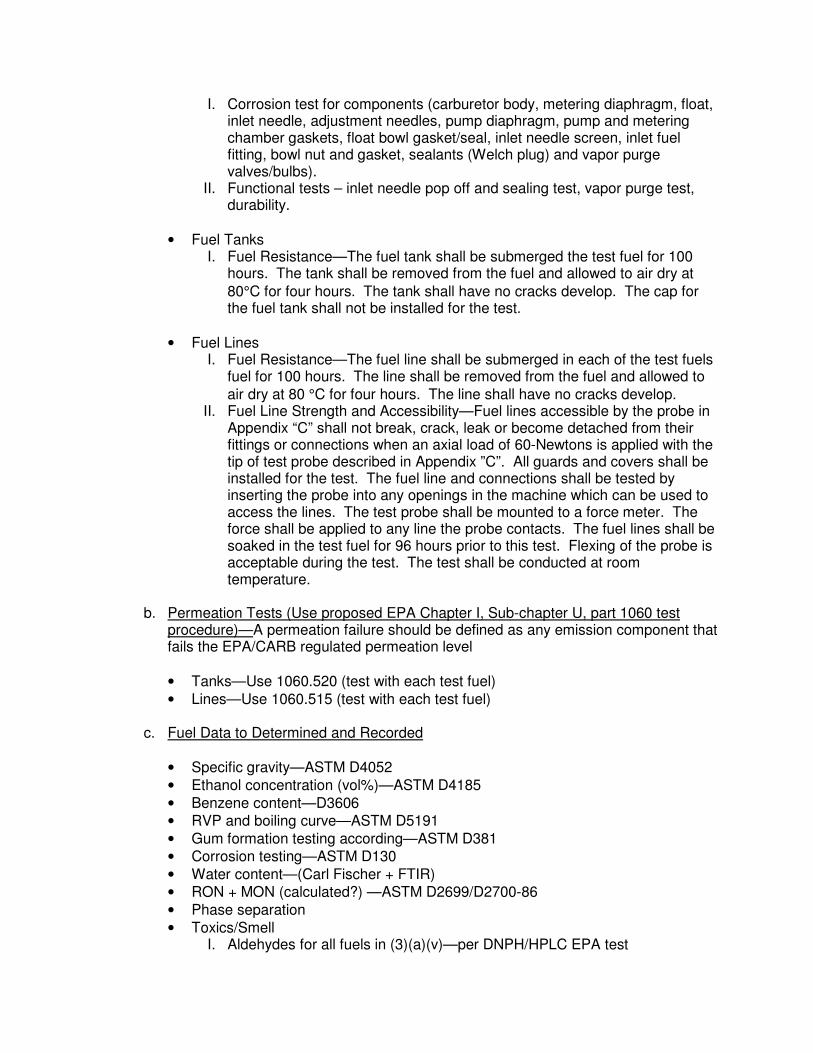
I. Corrosion test for components (carburetor body, metering diaphragm, float, inlet needle, adjustment needles, pump diaphragm, pump and metering chamber gaskets, float bowl gasket/seal, inlet needle screen, inlet fuel fitting, bowl nut and gasket, sealants (Welch plug) and vapor purge valves/bulbs).
II. Functional tests – inlet needle pop off and sealing test, vapor purge test, durability.
• Fuel Tanks I. Fuel Resistance—The fuel tank shall be submerged the test fuel for 100
hours. The tank shall be removed from the fuel and allowed to air dry at
80°C for four hours. The tank shall have no cracks develop. The cap for the fuel tank shall not be installed for the test.
• Fuel Lines I. Fuel Resistance—The fuel line shall be submerged in each of the test fuels
fuel for 100 hours. The line shall be removed from the fuel and allowed to
air dry at 80 °C for four hours. The line shall have no cracks develop. II. Fuel Line Strength and Accessibility—Fuel lines accessible by the probe in
Appendix “C” shall not break, crack, leak or become detached from their fittings or connections when an axial load of 60-Newtons is applied with the tip of test probe described in Appendix ”C”. All guards and covers shall be installed for the test. The fuel line and connections shall be tested by inserting the probe into any openings in the machine which can be used to access the lines. The test probe shall be mounted to a force meter. The force shall be applied to any line the probe contacts. The fuel lines shall be soaked in the test fuel for 96 hours prior to this test. Flexing of the probe is acceptable during the test. The test shall be conducted at room temperature.
b. Permeation Tests (Use proposed EPA Chapter I, Sub-chapter U, part 1060 test
procedure)—A permeation failure should be defined as any emission component that fails the EPA/CARB regulated permeation level
• Tanks—Use 1060.520 (test with each test fuel)
• Lines—Use 1060.515 (test with each test fuel)
c. Fuel Data to Determined and Recorded
• Specific gravity—ASTM D4052
• Ethanol concentration (vol%)—ASTM D4185
• Benzene content—D3606
• RVP and boiling curve—ASTM D5191
• Gum formation testing according—ASTM D381
• Corrosion testing—ASTM D130
• Water content—(Carl Fischer + FTIR)
• RON + MON (calculated?) —ASTM D2699/D2700-86
• Phase separation
• Toxics/Smell I. Aldehydes for all fuels in (3)(a)(v)—per DNPH/HPLC EPA test
II. Aromatic Substances (BTXE) —per gas chromatographic test
(7) Other Tests
a. Fuel Compatibility Tests with HH engines—See Pass-fail criteria below.
• Mixability of oil in fuel—Use SAE J1536 F/M Category 2. Results should be the same for each fuel tested.
• Storage compatibility—Test with fuel stored in product for 12 months including exposure to free water and a temperature range -20° F to 130° F. Failure is deemed if any proposed fuel presents results with higher corrosion or different fuel changes compared with existing cert/market fuels.
• Phase Separation (water)—phase separation of proposed fuels should be no greater than existing cert/market fuels.
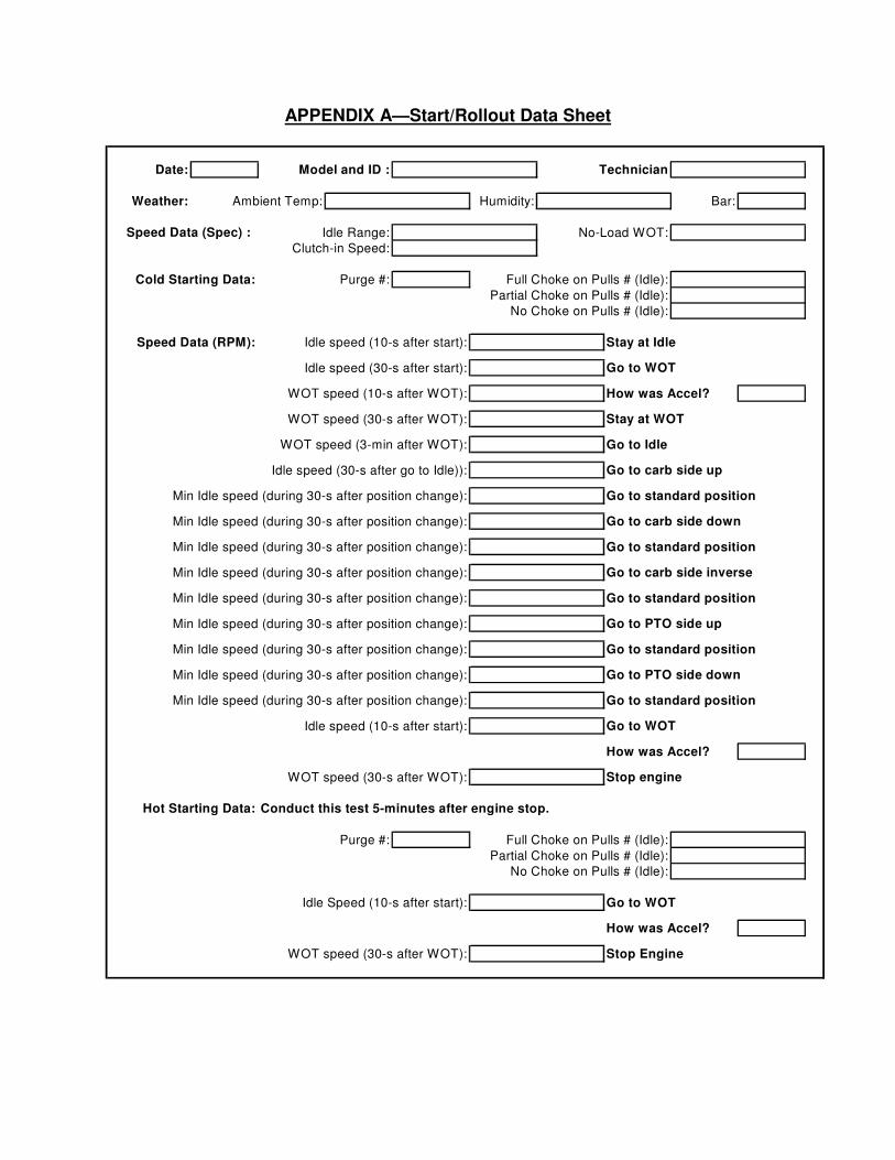
APPENDIX A—Start/Rollout Data Sheet
Date: Model and ID : Technician
Weather: Ambient Temp: Humidity: Bar:
Speed Data (Spec) : Idle Range: No-Load WOT:
Clutch-in Speed:
Cold Starting Data: Purge #: Full Choke on Pulls # (Idle):
Partial Choke on Pulls # (Idle):
No Choke on Pulls # (Idle):
Speed Data (RPM): Idle speed (10-s after start): Stay at Idle
Idle speed (30-s after start): Go to WOT
WOT speed (10-s after WOT): How was Accel?
WOT speed (30-s after WOT): Stay at WOT
WOT speed (3-min after WOT): Go to Idle
Idle speed (30-s after go to Idle)): Go to carb side up
Min Idle speed (during 30-s after position change): Go to standard position
Min Idle speed (during 30-s after position change): Go to carb side down
Min Idle speed (during 30-s after position change): Go to standard position
Min Idle speed (during 30-s after position change): Go to carb side inverse
Min Idle speed (during 30-s after position change): Go to standard position
Min Idle speed (during 30-s after position change): Go to PTO side up
Min Idle speed (during 30-s after position change): Go to standard position
Min Idle speed (during 30-s after position change): Go to PTO side down
Min Idle speed (during 30-s after position change): Go to standard position
Idle speed (10-s after start): Go to WOT
How was Accel?
WOT speed (30-s after WOT): Stop engine
Hot Starting Data: Conduct this test 5-minutes after engine stop.
Purge #: Full Choke on Pulls # (Idle):
Partial Choke on Pulls # (Idle):
No Choke on Pulls # (Idle):
Idle Speed (10-s after start): Go to WOT
How was Accel?
WOT speed (30-s after WOT): Stop Engine
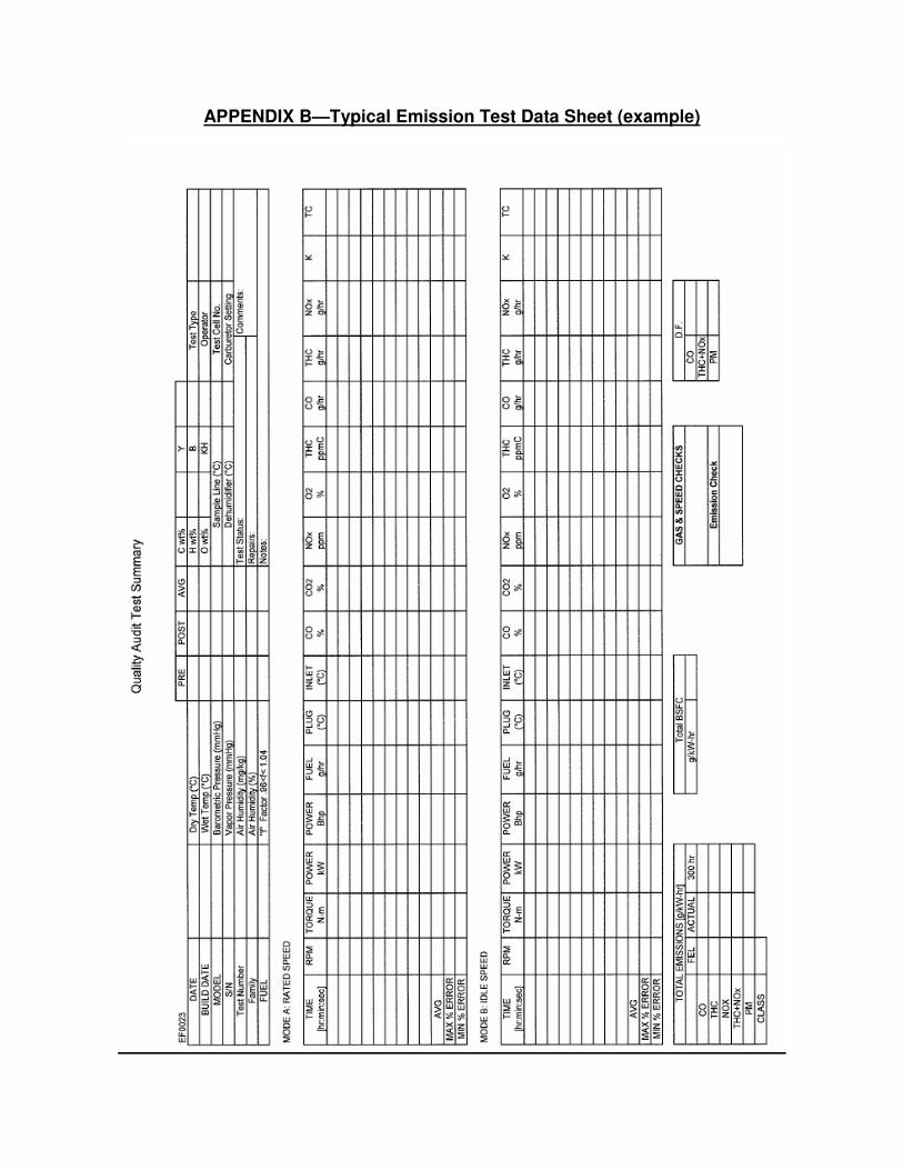
APPENDIX B—Typical Emission Test Data Sheet (example)
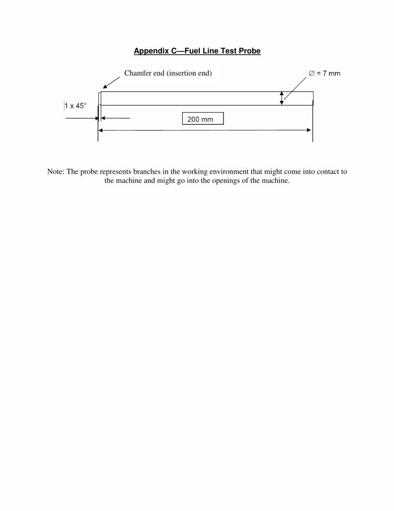
Appendix C—Fuel Line Test Probe
Note: The probe represents branches in the working environment that might come into contact to
the machine and might go into the openings of the machine.
Chamfer end (insertion end)
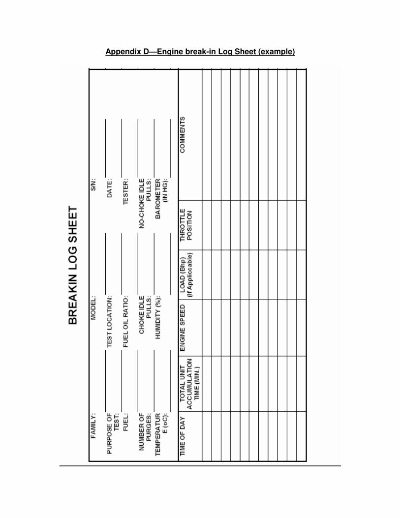
Appendix D—Engine break-in Log Sheet (example)
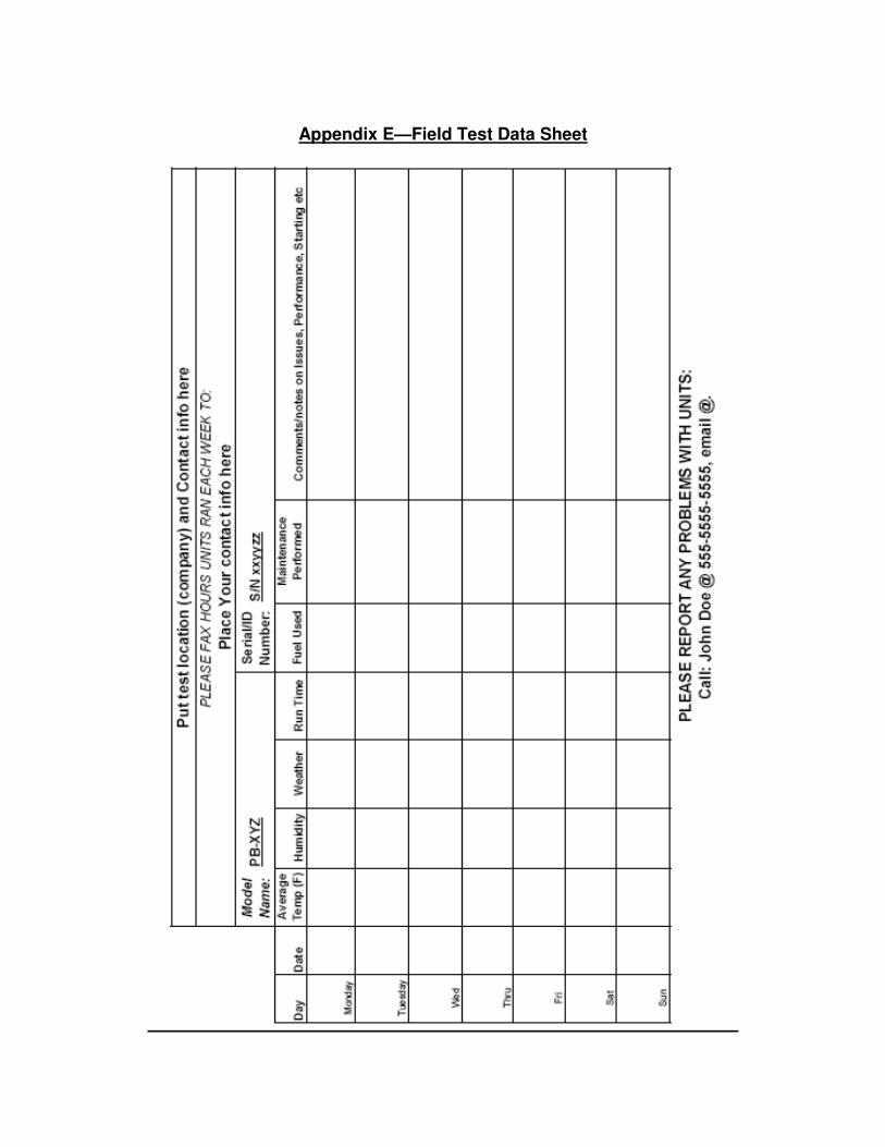
Appendix E—Field Test Data Sheet

EXHIBIT H
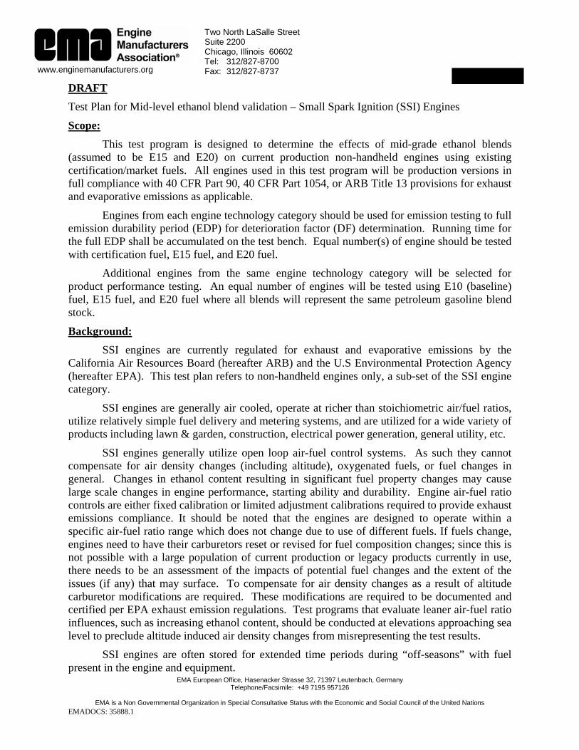
EMA European Office, Hasenacker Strasse 32, 71397 Leutenbach, Germany Telephone/Facsimile: +49 7195 957126
EMA is a Non Governmental Organization in Special Consultative Status with the Economic and Social Council of the United Nations
EMADOCS: 35888.1
Two North LaSalle Street Suite 2200 Chicago, Illinois 60602 Tel: 312/827-8700 Fax: 312/827-8737 www.enginemanufacturers.org Exhibit G
DRAFT Test Plan for Mid-level ethanol blend validation – Small Spark Ignition (SSI) Engines
Scope: This test program is designed to determine the effects of mid-grade ethanol blends
(assumed to be E15 and E20) on current production non-handheld engines using existing certification/market fuels. All engines used in this test program will be production versions in full compliance with 40 CFR Part 90, 40 CFR Part 1054, or ARB Title 13 provisions for exhaust and evaporative emissions as applicable.
Engines from each engine technology category should be used for emission testing to full emission durability period (EDP) for deterioration factor (DF) determination. Running time for the full EDP shall be accumulated on the test bench. Equal number(s) of engine should be tested with certification fuel, E15 fuel, and E20 fuel.
Additional engines from the same engine technology category will be selected for product performance testing. An equal number of engines will be tested using E10 (baseline) fuel, E15 fuel, and E20 fuel where all blends will represent the same petroleum gasoline blend stock.
Background: SSI engines are currently regulated for exhaust and evaporative emissions by the
California Air Resources Board (hereafter ARB) and the U.S Environmental Protection Agency (hereafter EPA). This test plan refers to non-handheld engines only, a sub-set of the SSI engine category.
SSI engines are generally air cooled, operate at richer than stoichiometric air/fuel ratios, utilize relatively simple fuel delivery and metering systems, and are utilized for a wide variety of products including lawn & garden, construction, electrical power generation, general utility, etc.
SSI engines generally utilize open loop air-fuel control systems. As such they cannot compensate for air density changes (including altitude), oxygenated fuels, or fuel changes in general. Changes in ethanol content resulting in significant fuel property changes may cause large scale changes in engine performance, starting ability and durability. Engine air-fuel ratio controls are either fixed calibration or limited adjustment calibrations required to provide exhaust emissions compliance. It should be noted that the engines are designed to operate within a specific air-fuel ratio range which does not change due to use of different fuels. If fuels change, engines need to have their carburetors reset or revised for fuel composition changes; since this is not possible with a large population of current production or legacy products currently in use, there needs to be an assessment of the impacts of potential fuel changes and the extent of the issues (if any) that may surface. To compensate for air density changes as a result of altitude carburetor modifications are required. These modifications are required to be documented and certified per EPA exhaust emission regulations. Test programs that evaluate leaner air-fuel ratio influences, such as increasing ethanol content, should be conducted at elevations approaching sea level to preclude altitude induced air density changes from misrepresenting the test results.
SSI engines are often stored for extended time periods during “off-seasons” with fuel present in the engine and equipment.
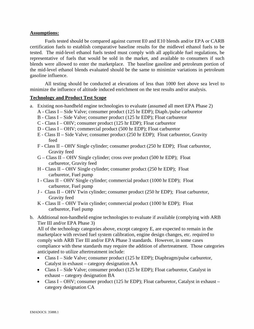
EMADOCS: 35888.1
Assumptions: Fuels tested should be compared against current E0 and E10 blends and/or EPA or CARB
certification fuels to establish comparative baseline results for the midlevel ethanol fuels to be tested. The mid-level ethanol fuels tested must comply with all applicable fuel regulations, be representative of fuels that would be sold in the market, and available to consumers if such blends were allowed to enter the marketplace. The baseline gasoline and petroleum portion of the mid-level ethanol blends evaluated should be the same to minimize variations in petroleum gasoline influence.
All testing should be conducted at elevations of less than 1000 feet above sea level to minimize the influence of altitude induced enrichment on the test results and/or analysis.
Technology and Product Test Scope a. Existing non-handheld engine technologies to evaluate (assumed all meet EPA Phase 2)
A - Class I – Side Valve; consumer product (125 hr EDP); Diaph./pulse carburetor B - Class I – Side Valve; consumer product (125 hr EDP); Float carburetor C - Class I – OHV; consumer product (125 hr EDP); Float carburetor D - Class I – OHV; commercial product (500 hr EDP); Float carburetor E - Class II – Side Valve; consumer product (250 hr EDP); Float carburetor, Gravity
feed F - Class II – OHV Single cylinder; consumer product (250 hr EDP); Float carburetor,
Gravity feed G – Class II – OHV Single cylinder; cross over product (500 hr EDP); Float
carburetor, Gravity feed H - Class II – OHV Single cylinder; consumer product (250 hr EDP); Float
carburetor, Fuel pump I - Class II – OHV Single cylinder; commercial product (1000 hr EDP); Float
carburetor, Fuel pump J - Class II – OHV Twin cylinder; consumer product (250 hr EDP); Float carburetor,
Gravity feed K - Class II – OHV Twin cylinder; commercial product (1000 hr EDP); Float
carburetor, Fuel pump
b. Additional non-handheld engine technologies to evaluate if available (complying with ARB Tier III and/or EPA Phase 3) All of the technology categories above, except category E, are expected to remain in the marketplace with revised fuel system calibration, engine design changes, etc. required to comply with ARB Tier III and/or EPA Phase 3 standards. However, in some cases compliance with these standards may require the addition of aftertreatment. Those categories anticipated to utilize aftertreatment include: • Class I – Side Valve; consumer product (125 hr EDP); Diaphragm/pulse carburetor,
Catalyst in exhaust – category designation AA • Class I – Side Valve; consumer product (125 hr EDP); Float carburetor, Catalyst in
exhaust – category designation BA • Class I – OHV; consumer product (125 hr EDP); Float carburetor, Catalyst in exhaust –
category designation CA
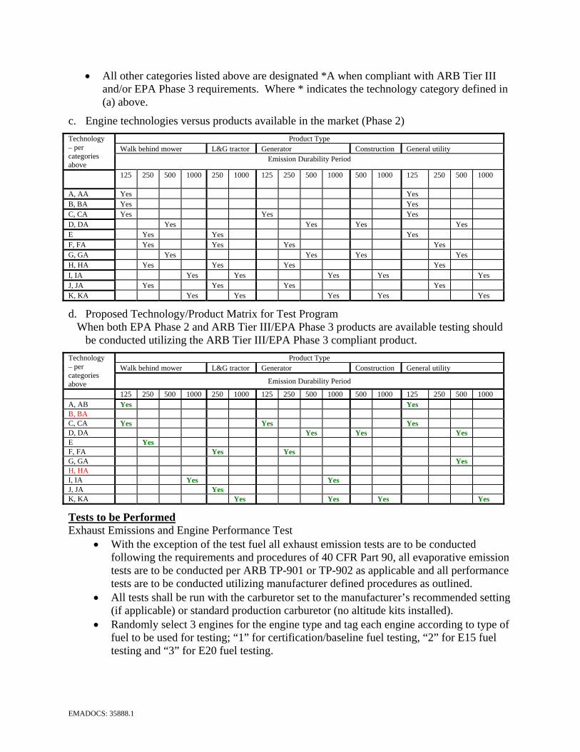
EMADOCS: 35888.1
• All other categories listed above are designated *A when compliant with ARB Tier III and/or EPA Phase 3 requirements. Where * indicates the technology category defined in (a) above.
c. Engine technologies versus products available in the market (Phase 2) Product Type
Walk behind mower L&G tractor Generator Construction General utility Technology – per categories above
Emission Durability Period
125
250 500 1000 250 1000 125 250 500 1000 500 1000 125 250 500 1000
A, AA Yes Yes B, BA Yes Yes C, CA Yes Yes Yes D, DA Yes Yes Yes Yes E Yes Yes Yes F, FA Yes Yes Yes Yes G, GA Yes Yes Yes Yes H, HA Yes Yes Yes Yes I, IA Yes Yes Yes Yes Yes J, JA Yes Yes Yes Yes K, KA Yes Yes Yes Yes Yes
d. Proposed Technology/Product Matrix for Test Program When both EPA Phase 2 and ARB Tier III/EPA Phase 3 products are available testing should
be conducted utilizing the ARB Tier III/EPA Phase 3 compliant product. Product Type
Walk behind mower L&G tractor Generator Construction General utility Technology – per categories above Emission Durability Period
125 250 500 1000 250 1000 125 250 500 1000 500 1000 125 250 500 1000 A, AB Yes Yes B, BA C, CA Yes Yes Yes D, DA Yes Yes Yes E Yes F, FA Yes Yes G, GA Yes H, HA I, IA Yes Yes J, JA Yes K, KA Yes Yes Yes Yes
Tests to be Performed Exhaust Emissions and Engine Performance Test
• With the exception of the test fuel all exhaust emission tests are to be conducted following the requirements and procedures of 40 CFR Part 90, all evaporative emission tests are to be conducted per ARB TP-901 or TP-902 as applicable and all performance tests are to be conducted utilizing manufacturer defined procedures as outlined.
• All tests shall be run with the carburetor set to the manufacturer’s recommended setting (if applicable) or standard production carburetor (no altitude kits installed).
• Randomly select 3 engines for the engine type and tag each engine according to type of fuel to be used for testing; “1” for certification/baseline fuel testing, “2” for E15 fuel testing and “3” for E20 fuel testing.
EMADOCS: 35888.1
• Standard engine/product set-up and break-in procedures must be used as defined by the manufacturer.
• Any operational and performance issues during and throughout the test period shall be reported.
• Test results with E15 and E20 fuels shall be compared to the baseline engine tested on emission certification test fuel or E10 baseline fuel as applicable.
• Exhaust emission report should include the test information required by the EPA for certification (see sample EPA test data sheet in Appendix A).
• Engine performance test information to include critical functionality as described.
Emissions Testing: Exhaust:
Failure is defined as any test result or deterioration factor adjusted test result that exceeds the applicable EPA/ARB standard level.
Exhaust emissions to be tested utilizing EPA Cycle A, B, or approved alternate as applicable. Exhaust emissions shall be evaluated when the engine is new (after break-in period), at the
mid point of the hour accumulation period, and after the full useful life hour accumulation period.
Monitor and report weighted brake specific fuel consumption for each emission test.
Evaporative Emission Testing: Failure is defined as any test result that exceeds the applicable EPA/ARB standard level. Evaporative emissions shall be tested per ARB diurnal or permeation testing as applicable
utilizing ARB test procedure TP901 or TP902 as applicable.
Performance Tests: Starting and Acceleration:
Failure is defined as the inability to start within 5 starting attempts (pulls if manual, 15 seconds cranking if electric) or inability to accelerate and maintain operating speed within a reasonable time period after starting (maybe temperature dependent).
Cold start performance to be evaluated at the following temperatures: Year round product: 23 to 27° C, ±2° C, and -18 to -22° C Summer only product: 23 to 27° C and ±2° C Winter only product: ±2° C and -26 to -30° C
Hot start performance to be evaluated at the following temperatures: Year round and summer product: 40 to 44° C Winter only product: 7 to 10° C
Hot restart performance to be evaluated at the hot start temperatures after operation for 1 hour or approximately 50% of fuel capacity, whichever is longer, followed by a shut down period of 5 minutes prior to the first restarting attempt.
Carburetor & Breather Icing Failure is defined as the inability to continue operation through one full fuel tank capacity,
refueling and continued operation for at least one half of fuel tank capacity. Operating conditions: temperature 2 to 5° C and ambient relative humidity of 97 to 100%
Governor Stability/Regulation and Load Pick-up Generators - Reference SAE Procedure for Evaluating Transient Response of Small Engine
Driven Generator Sets SAE J1444 for acceptance/failure criteria.
EMADOCS: 35888.1
Other categories – failure is defined by excessive speed loss under load (>500 rpm), instability of rpm (audible speed fluctuation, or ± 75 rpm), or inability to pick up 75% load when load clutching mechanism is engaged.
Vapor Lock – note that product applications are required for vapor lock testing due to interactions between the engine and the product.
Failure defined as the inability to continue operation through one full fuel tank capacity, refueling and continued operation for at least one half of fuel tank capacity.
Operating conditions: Year round and summer product: 40 to 44° C Winter only product: 7 to 10° C
Durability and fuel consumption Failure is defined as the inability to complete the prescribed aging period, excessive oil
consumption, or inability to produce a minimum of 90% of power available at either rated speed or peak torque speed when compared with baseline testing power levels, or unacceptable critical engine temperatures.
All engines shall be instrumented to allow monitoring of critical temperatures as prescribed by their respective manufacturers.
All engines shall be operated over a test cycle that represents either emission test cycle A or B as appropriate, without idle, where the test cycle is 2 hours in duration and repeated for the emission durability period. All engines shall be stopped ever 8 hours to check and replenish oil level. All engines shall be maintained per manufacturer defined maintenance intervals for lubricating oil, air filter, spark plug, etc.
All engines shall be monitored and crankcase oil consumption reported utilizing drain and weigh procedures for both additions and changes.
All engines shall have crankcase oil properties evaluated for wear metals and fuel components at each oil change.
All engines tested shall be inspected by their respective manufacturer after testing to evaluate internal engine conditions including compression, cylinder leak down, combustion chamber deposits, piston deposits and condition, bearing condition, cylinder bore condition, intake system deposits, exhaust system integrity, etc.
Fuel System Component Compatibility and Exposure Tests Failure is defined as changes in materials properties that result in unacceptable product
performance or increased safety risk. Test both short term (30 day exposure) and long term (2 year exposure) exposure of fuel
system materials with proposed ethanol blends to determine changes in physical properties (dimensional and functional).
Fuel utilized for testing shall have maximum content of water, acids, etc. allowed by ASTM finished fuel standards.
Short term testing to be conducted at 40-44° C Long term testing to be conducted over a temperature and relative humidity range of 15-44°
C and 50-100% respectfully. All ambient vents shall remain open to the atmosphere during the aging process. Fuel additions required to maintain a minimum of 10% fuel capacity shall be documents for both volume and chemistry of the fuel added.
Test fuel properties including oxidation stability, peroxide level, etc. shall be recorded at the beginning and end of the test.

EXHIBIT I
1
Mid Level Ethanol Blend
Experimental Framework – EPA
Staff Recommendations
Karl SimonEPA Office of Transportation and Air Quality
API Technology Committee MeetingChicago
6/4/08
2
Outline
• Introduction
– Blend Wall
– Waiver qualification
– Concerns about data submission & quality
• Experimental framework
– Fuel properties
– On Road
– Non Road
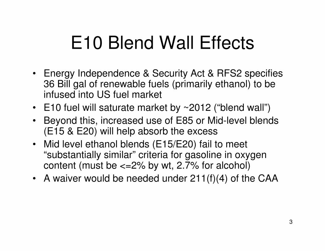
3
E10 Blend Wall Effects
• Energy Independence & Security Act & RFS2 specifies 36 Bill gal of renewable fuels (primarily ethanol) to be infused into US fuel market
• E10 fuel will saturate market by ~2012 (“blend wall”)
• Beyond this, increased use of E85 or Mid-level blends (E15 & E20) will help absorb the excess
• Mid level ethanol blends (E15/E20) fail to meet “substantially similar” criteria for gasoline in oxygen content (must be <=2% by wt, 2.7% for alcohol)
• A waiver would be needed under 211(f)(4) of the CAA
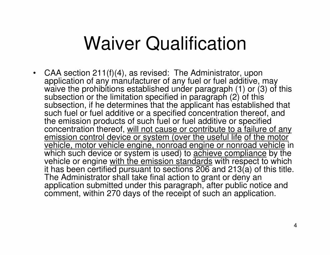
4
Waiver Qualification
• CAA section 211(f)(4), as revised: The Administrator, upon application of any manufacturer of any fuel or fuel additive, may waive the prohibitions established under paragraph (1) or (3) of this subsection or the limitation specified in paragraph (2) of this subsection, if he determines that the applicant has established that such fuel or fuel additive or a specified concentration thereof, and the emission products of such fuel or fuel additive or specifiedconcentration thereof, will not cause or contribute to a failure of any emission control device or system (over the useful life of the motor vehicle, motor vehicle engine, nonroad engine or nonroad vehicle in which such device or system is used) to achieve compliance by the vehicle or engine with the emission standards with respect to which it has been certified pursuant to sections 206 and 213(a) of this title. The Administrator shall take final action to grant or deny an application submitted under this paragraph, after public notice and comment, within 270 days of the receipt of such an application.
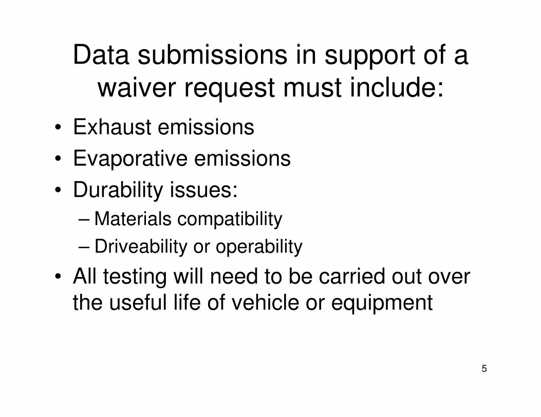
5
Data submissions in support of a
waiver request must include:
• Exhaust emissions
• Evaporative emissions
• Durability issues:
– Materials compatibility
– Driveability or operability
• All testing will need to be carried out over the useful life of vehicle or equipment
6
Experimental Framework
• The following is an experimental framework for an example waiver test program
• This framework provides suggestions and describes what a test program MAY look like
• Actual implemented test programs are expected to be similar, giving statistically meaningful and defensible results

7
On Road: What are the factors for
the test program?• Fuels
– What type, how many? (E0, E10, E15, E20)– Fuels should have “typical” properties
• Vehicles– Type (FFVs excluded)
– Model year, make, model– How many? Repeat tests?
• Tests– Exhaust/evap
– Test procedures• Cycle, Temperature conditions
– Aging/durability procedures
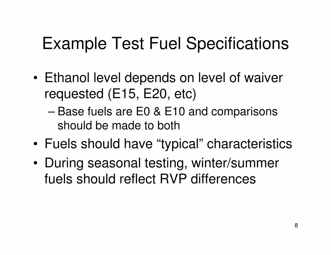
8
Example Test Fuel Specifications
• Ethanol level depends on level of waiver requested (E15, E20, etc)
– Base fuels are E0 & E10 and comparisons
should be made to both
• Fuels should have “typical” characteristics
• During seasonal testing, winter/summer fuels should reflect RVP differences
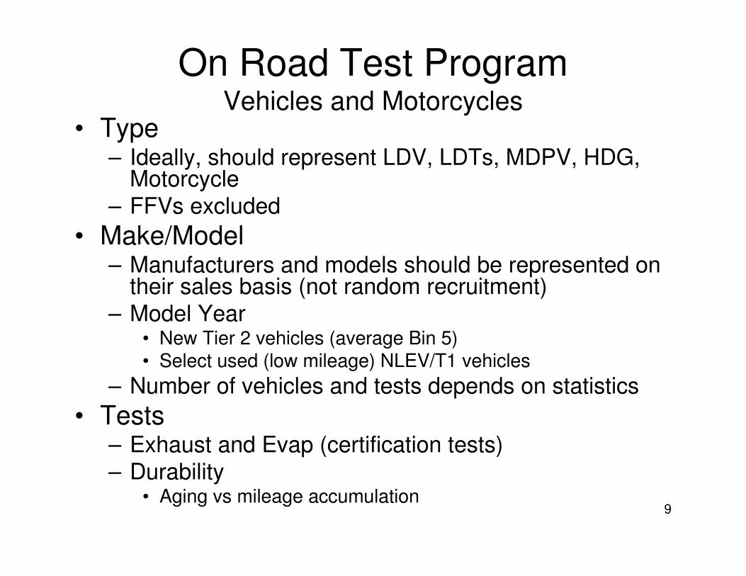
9
On Road Test ProgramVehicles and Motorcycles
• Type– Ideally, should represent LDV, LDTs, MDPV, HDG,
Motorcycle
– FFVs excluded
• Make/Model– Manufacturers and models should be represented on
their sales basis (not random recruitment)
– Model Year• New Tier 2 vehicles (average Bin 5)• Select used (low mileage) NLEV/T1 vehicles
– Number of vehicles and tests depends on statistics
• Tests– Exhaust and Evap (certification tests)
– Durability• Aging vs mileage accumulation
10
On Road Test ProgramVehicle Durability Example
• FUL mileage of 120k/150k on new blend– Emissions tests at defined mileage breakpoints
• E0, E10 and new blend fuel tested at each point– Exhaust & Evaporative emissions
– Mileage accumulation approaches (combination expected)• Traditional durability program (mileage accumulation dyno/track)
• “Real world” on road aging (e.g. OBD durability)– Seasonal and regional climate change exposure– On road environment (e.g. fuel sloshing, moisture, altitude, prolonged road grades)
• Statistically based sample size – New Tier 2 vehicles (average Bin 5)
– Select used (<=50k) interim non-Tier 2/NLEV/Tier 1 type vehicles
• Selection considerations:– High volume durability groups preferred
– Fleet make-up related to fuel timing (Tier 2, NLEV, Tier 1)• LDV/LLDT 10 yr FUL
• HLDT/MDPV 11 yr FUL
• Motorcycles may follow similar approach– 20k FUL
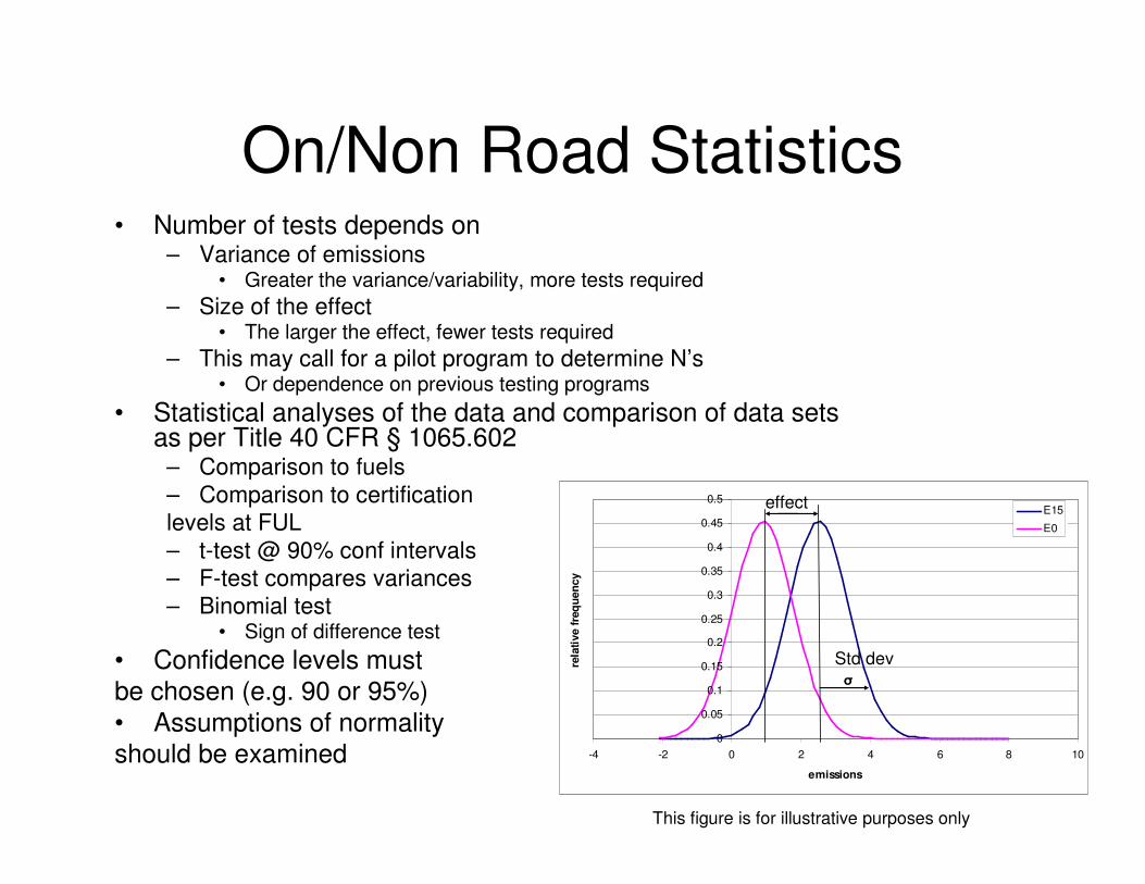
11
On/Non Road Statistics• Number of tests depends on
– Variance of emissions• Greater the variance/variability, more tests required
– Size of the effect• The larger the effect, fewer tests required
– This may call for a pilot program to determine N’s• Or dependence on previous testing programs
• Statistical analyses of the data and comparison of data sets as per Title 40 CFR § 1065.602
– Comparison to fuels
– Comparison to certification
levels at FUL
– t-test @ 90% conf intervals
– F-test compares variances
– Binomial test• Sign of difference test
• Confidence levels must
be chosen (e.g. 90 or 95%)
• Assumptions of normality
should be examined0
0.05
0.1
0.15
0.2
0.25
0.3
0.35
0.4
0.45
0.5
-4 -2 0 2 4 6 8 10
emissions
rela
tive f
req
uen
cy
E15
E0
σ
This figure is for illustrative purposes only
effect
Std dev
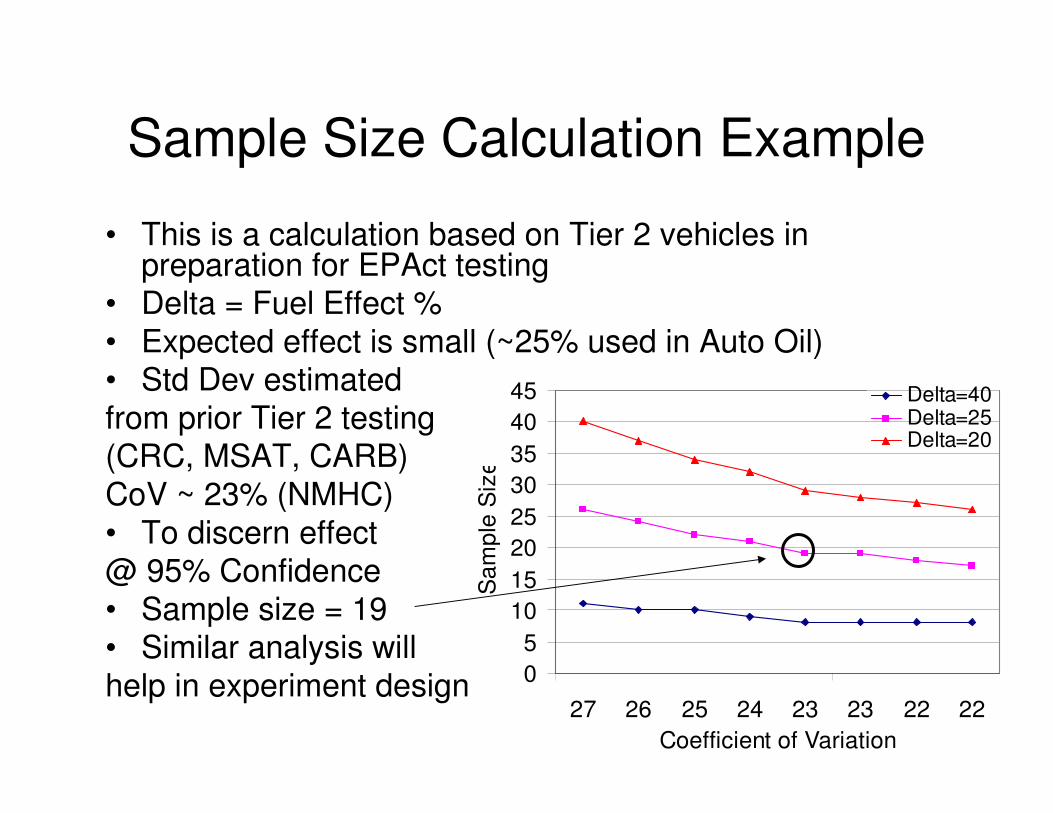
12
0
5
10
15
20
25
30
35
40
45
27 26 25 24 23 23 22 22
Coefficient of Variation
Sa
mp
le S
ize
Delta=40 Delta=25Delta=20
Sample Size Calculation Example
• This is a calculation based on Tier 2 vehicles in preparation for EPAct testing
• Delta = Fuel Effect %
• Expected effect is small (~25% used in Auto Oil)• Std Dev estimated
from prior Tier 2 testing (CRC, MSAT, CARB)
CoV ~ 23% (NMHC)
• To discern effect @ 95% Confidence
• Sample size = 19• Similar analysis will
help in experiment design
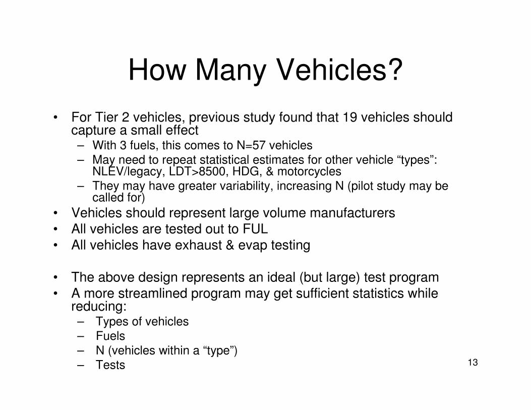
13
How Many Vehicles?
• For Tier 2 vehicles, previous study found that 19 vehicles should capture a small effect– With 3 fuels, this comes to N=57 vehicles
– May need to repeat statistical estimates for other vehicle “types”: NLEV/legacy, LDT>8500, HDG, & motorcycles
– They may have greater variability, increasing N (pilot study may be called for)
• Vehicles should represent large volume manufacturers • All vehicles are tested out to FUL• All vehicles have exhaust & evap testing
• The above design represents an ideal (but large) test program • A more streamlined program may get sufficient statistics while
reducing:– Types of vehicles
– Fuels
– N (vehicles within a “type”)
– Tests
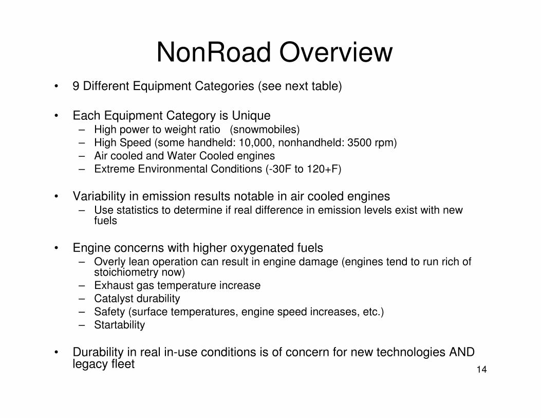
14
NonRoad Overview• 9 Different Equipment Categories (see next table)
• Each Equipment Category is Unique – High power to weight ratio (snowmobiles)
– High Speed (some handheld: 10,000, nonhandheld: 3500 rpm)
– Air cooled and Water Cooled engines
– Extreme Environmental Conditions (-30F to 120+F)
• Variability in emission results notable in air cooled engines– Use statistics to determine if real difference in emission levels exist with new
fuels
• Engine concerns with higher oxygenated fuels– Overly lean operation can result in engine damage (engines tend to run rich of
stoichiometry now)
– Exhaust gas temperature increase
– Catalyst durability
– Safety (surface temperatures, engine speed increases, etc.)
– Startability
• Durability in real in-use conditions is of concern for new technologies AND legacy fleet

15
HC: 4 / NOx: 69.8
2 str/4 str
*certified by equip mfr
10,000km or
1000 hours132006ATV
HC: 3/NOx: 102.2
2 stroke: air/water/DI
*certified by equip mfr
400 hours/
8000 km
132006Snowmobile
HC: -/ NOx: -0.07
4 stroke: carb/EFI
*certified by equip mfr
HC: 9 / NOx:32.04 stroke: carb/EFI/cat480202010
Marine Sterndrive/
Inboard
HC: 8 / NOx: 11.2
4 stroke automotive tech
(few gas/mostly LPG)
5000 hrs
(cert 2500)252004Large SI
13
10
25
6
3
6
2
2.5
1
Modeling
Average
Life (Yrs)
2006
1998
1998
1997
1997
First
Emission
Standards
250/500/1000
10,000km
350
350
125/250/500
50/300
Regulatory
Emission
Useful Life
(Hours)
HC: 5 / NOx: -2.4
2 str/4 str
*certified by equip mfrNR Motorcycle
HC: - / NOx: 70.54 stroke: carb/open EFI
HC: 6 / NOx: 90.82 stroke: carb/DI
Recmarine PWC
HC: - / NOx: 52.44 stroke: carb/DI/supercharge
HC: 1 / NOx: 47.12 stroke: carb/DI
Recmarine Outboard
4 stroke/cat (Residential)
4 stroke (Commercial)
HC: 2 / NOx: 285.4
4 stroke/cat (Residential)
4 stroke/cat (Commercial)
Small SI <19kW:
Nonhandheld
Class I engines
(ex: lawnmower/
Class II engines
(ex: lawn tractor)
HC: 7 / NOx: 832.9 2 strk
5.7 4 strk
2 & 4 stroke/cat (Residential)
2 & 4 stroke/cat (Commercial)
Small SI <19kW:
Handheld
(ex: trimmer)
HC/NOx
Exhaust
Rating
(1-10)
2008 Model
Population
(Millions)
Type
(certified by engine mfr
unless otherwise noted)
NONROAD
EQUIPMENT/
VEHICLE
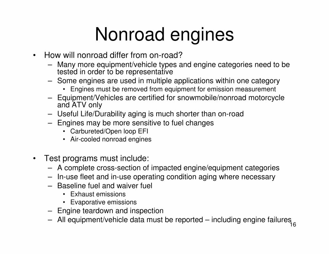
16
Nonroad engines• How will nonroad differ from on-road?
– Many more equipment/vehicle types and engine categories need to be tested in order to be representative
– Some engines are used in multiple applications within one category • Engines must be removed from equipment for emission measurement
– Equipment/Vehicles are certified for snowmobile/nonroad motorcycle and ATV only
– Useful Life/Durability aging is much shorter than on-road
– Engines may be more sensitive to fuel changes • Carbureted/Open loop EFI
• Air-cooled nonroad engines
• Test programs must include:– A complete cross-section of impacted engine/equipment categories
– In-use fleet and in-use operating condition aging where necessary
– Baseline fuel and waiver fuel• Exhaust emissions
• Evaporative emissions
– Engine teardown and inspection
– All equipment/vehicle data must be reported – including engine failures

17
Non Road Test Program Recruitment
• Obtain the Equipment for the Study
– Sufficient number of models to represent • major sales models, • variety of engine technologies, • hp range, speed range, • applications, markets, • etc.
– New Equipment/Vehicles• Range of engine tech may include catalyst, 2stroke, 4 stroke, carbureted, EFI• 2-3 equipment/vehicle per model per fuel (due to production variability)
– Legacy equipment/vehicles• With low/mid life mileage
– Range of technologies/manufacturers/applications, etc.
– Future technology engines for upcoming new emission regulations, if available
– Snowmobile, Nonroad motorcycles and ATV’s are certified by equipment manufacturer
• Consider equipment manufacturer differences
– Pilot study may be required to determine sample sizes to discern fuel effects but streamlining may be required due to sheer variety of equipment types

18
Non Road Emission & Durability Test Program
Example
• Exhaust Emission Testing per Engine/Vehicle– New: (at least 3 points) New, mid-life and end of durability cycle.
– Legacy: (at least 2 points) Received and end of aging.
– 3 emissions tests per test point on baseline and waiver fuel
• Perform statistical comparison to determine if there is a difference.
– Follow EPA regulatory test procedures for applicable equipment/vehicle
• Evaporative emissions tests– Follow EPA regulatory test procedures for applicable
equipment/vehicle
– Baseline and waiver fuel
– 2 points: New/Received and End of useful life for New and Legacy
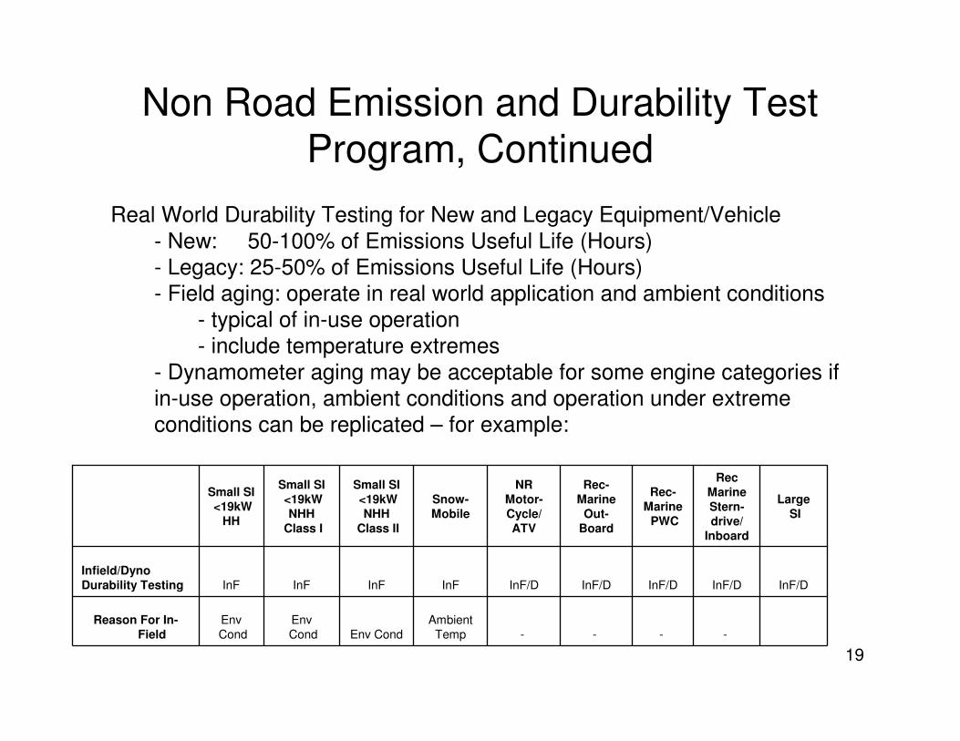
19
Non Road Emission and Durability Test Program, Continued
-
InF/D
Rec
Marine
Stern-
drive/
Inboard
InF/D
Large
SI
-
InF/D
NR
Motor-
Cycle/
ATV
--
Ambient
TempEnv Cond
Env
Cond
Env
Cond
Reason For In-
Field
InF/DInF/DInFInFInFInF
Infield/Dyno
Durability Testing
Rec-
Marine
PWC
Rec-
Marine
Out-
Board
Snow-
Mobile
Small SI
<19kW
NHH
Class II
Small SI
<19kW
NHH
Class I
Small SI
<19kW
HH
Real World Durability Testing for New and Legacy Equipment/Vehicle
- New: 50-100% of Emissions Useful Life (Hours)
- Legacy: 25-50% of Emissions Useful Life (Hours)
- Field aging: operate in real world application and ambient conditions
- typical of in-use operation
- include temperature extremes
- Dynamometer aging may be acceptable for some engine categories if
in-use operation, ambient conditions and operation under extreme
conditions can be replicated – for example:
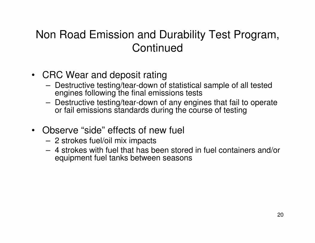
20
Non Road Emission and Durability Test Program,
Continued
• CRC Wear and deposit rating– Destructive testing/tear-down of statistical sample of all tested
engines following the final emissions tests– Destructive testing/tear-down of any engines that fail to operate
or fail emissions standards during the course of testing
• Observe “side” effects of new fuel– 2 strokes fuel/oil mix impacts– 4 strokes with fuel that has been stored in fuel containers and/or
equipment fuel tanks between seasons

EXHIBIT J
1
Vehicle Selection & Sample Size
Issues for Catalyst and Evap
Durability Testing
Nov 12, 2008

2
Waiver Qualification
• CAA section 211(f)(4), as revised: The Administrator, upon application of any manufacturer of any fuel or fuel additive, may waive the prohibitions established under paragraph (1) or (3) of this subsection or the limitation specified in paragraph (2) of this subsection, if he determines that the applicant has established that such fuel or fuel additive or a specified concentration thereof, and the emission products of such fuel or fuel additive or specifiedconcentration thereof, will not cause or contribute to a failure of any emission control device or system (over the useful life of the motor vehicle, motor vehicle engine, nonroad engine or nonroad vehicle in which such device or system is used) to achieve compliance by the vehicle or engine with the emission standards with respect to which it has been certified pursuant to sections 206 and 213(a) of this title. The Administrator shall take final action to grant or deny an application submitted under this paragraph, after public notice and comment, within 270 days of the receipt of such an application.
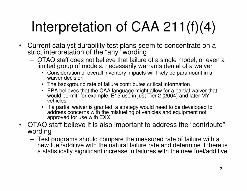
3
Interpretation of CAA 211(f)(4)• Current catalyst durability test plans seem to concentrate on a
strict interpretation of the “any” wording– OTAQ staff does not believe that failure of a single model, or even a
limited group of models, necessarily warrants denial of a waiver• Consideration of overall inventory impacts will likely be paramount in a
waiver decision• The background rate of failure contributes critical information• EPA believes that the CAA language might allow for a partial waiver that
would permit, for example, E15 use in just Tier 2 (2004) and later MY vehicles
• If a partial waiver is granted, a strategy would need to be developed to address concerns with the misfueling of vehicles and equipment not approved for use with EXX
• OTAQ staff believe it is also important to address the “contribute” wording– Test programs should compare the measured rate of failure with a
new fuel/additive with the natural failure rate and determine if there is a statistically significant increase in failures with the new fuel/additive
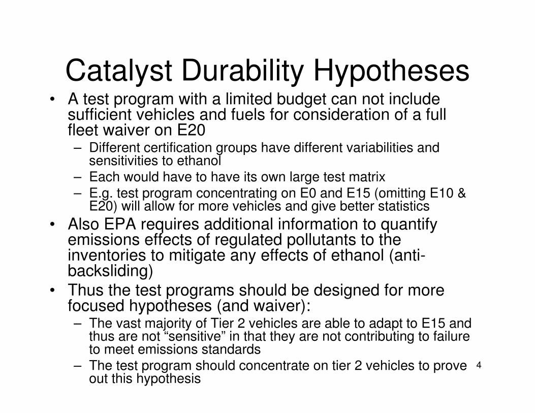
4
Catalyst Durability Hypotheses• A test program with a limited budget can not include
sufficient vehicles and fuels for consideration of a full fleet waiver on E20– Different certification groups have different variabilities and
sensitivities to ethanol– Each would have to have its own large test matrix– E.g. test program concentrating on E0 and E15 (omitting E10 &
E20) will allow for more vehicles and give better statistics
• Also EPA requires additional information to quantify emissions effects of regulated pollutants to the inventories to mitigate any effects of ethanol (anti-backsliding)
• Thus the test programs should be designed for more focused hypotheses (and waiver): – The vast majority of Tier 2 vehicles are able to adapt to E15 and
thus are not “sensitive” in that they are not contributing to failure to meet emissions standards
– The test program should concentrate on tier 2 vehicles to prove out this hypothesis
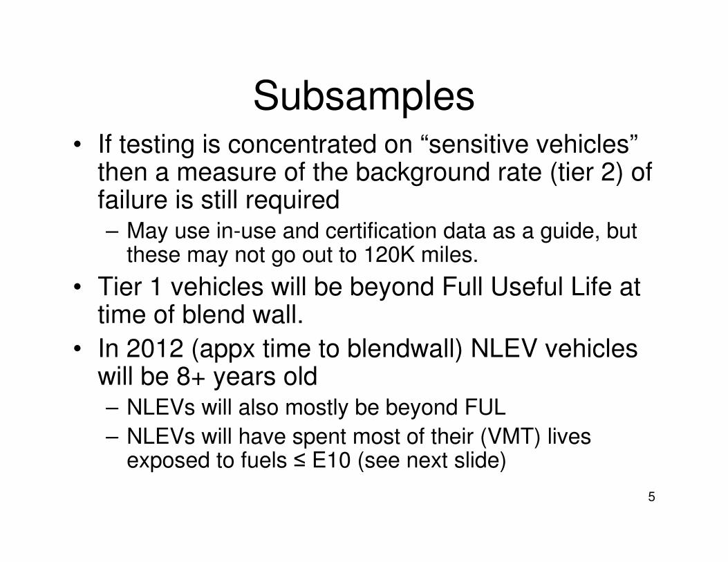
5
Subsamples• If testing is concentrated on “sensitive vehicles”
then a measure of the background rate (tier 2) of failure is still required– May use in-use and certification data as a guide, but
these may not go out to 120K miles.
• Tier 1 vehicles will be beyond Full Useful Life at time of blend wall.
• In 2012 (appx time to blendwall) NLEV vehicles will be 8+ years old– NLEVs will also mostly be beyond FUL
– NLEVs will have spent most of their (VMT) lives exposed to fuels ≤ E10 (see next slide)
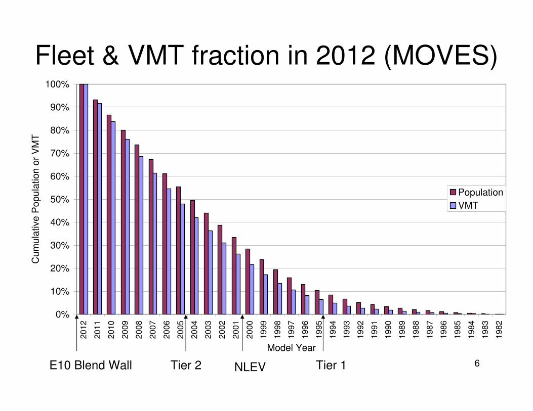
6
Fleet & VMT fraction in 2012 (MOVES)
0%
10%
20%
30%
40%
50%
60%
70%
80%
90%
100%2
012
20
11
20
10
20
09
20
08
20
07
20
06
20
05
20
04
20
03
20
02
20
01
20
00
19
99
19
98
19
97
19
96
19
95
19
94
19
93
19
92
19
91
19
90
19
89
19
88
19
87
19
86
19
85
19
84
19
83
19
82
Model Year
Cum
ula
tive
Pop
ula
tio
n o
r V
MT
Population
VMT
Tier 1NLEVTier 2E10 Blend Wall
7
Sample Size--Auto/Oil Procedures
• Taken from Auto/Oil Approach Found in L.J. Painter and Rutherford, J. A., “Statistical Design and Analysis Methods for the Auto/Oil Air Quality Research Program,” SAE Paper 920319, 1992.
• For Auto/Oil, sample size is the number of vehicles required to detect a statistically significant difference in emissions from different fuels
• Requires the following variance determinations:– Car x Fuel interaction (C x F)
– Repeat test variance
• Auto/Oil used GM data for estimates
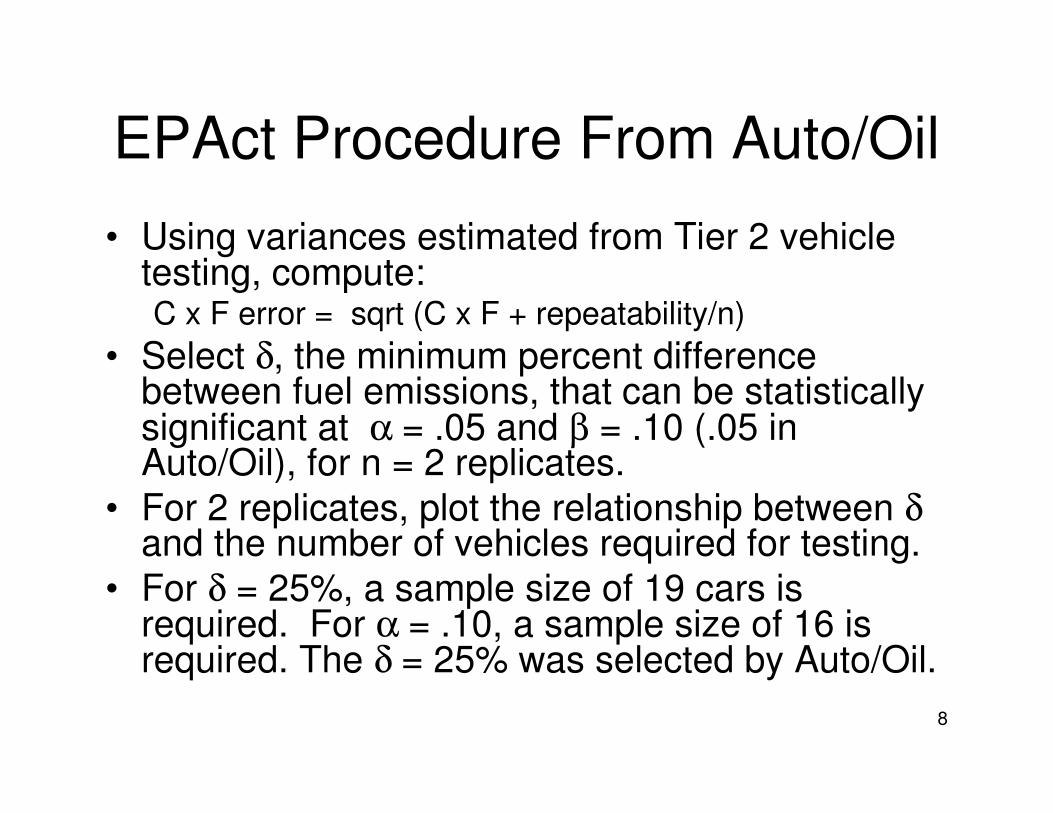
8
EPAct Procedure From Auto/Oil
• Using variances estimated from Tier 2 vehicle testing, compute:C x F error = sqrt (C x F + repeatability/n)
• Select δ, the minimum percent difference between fuel emissions, that can be statistically significant at α = .05 and β = .10 (.05 in Auto/Oil), for n = 2 replicates.
• For 2 replicates, plot the relationship between δand the number of vehicles required for testing.
• For δ = 25%, a sample size of 19 cars is required. For α = .10, a sample size of 16 is required. The δ = 25% was selected by Auto/Oil.
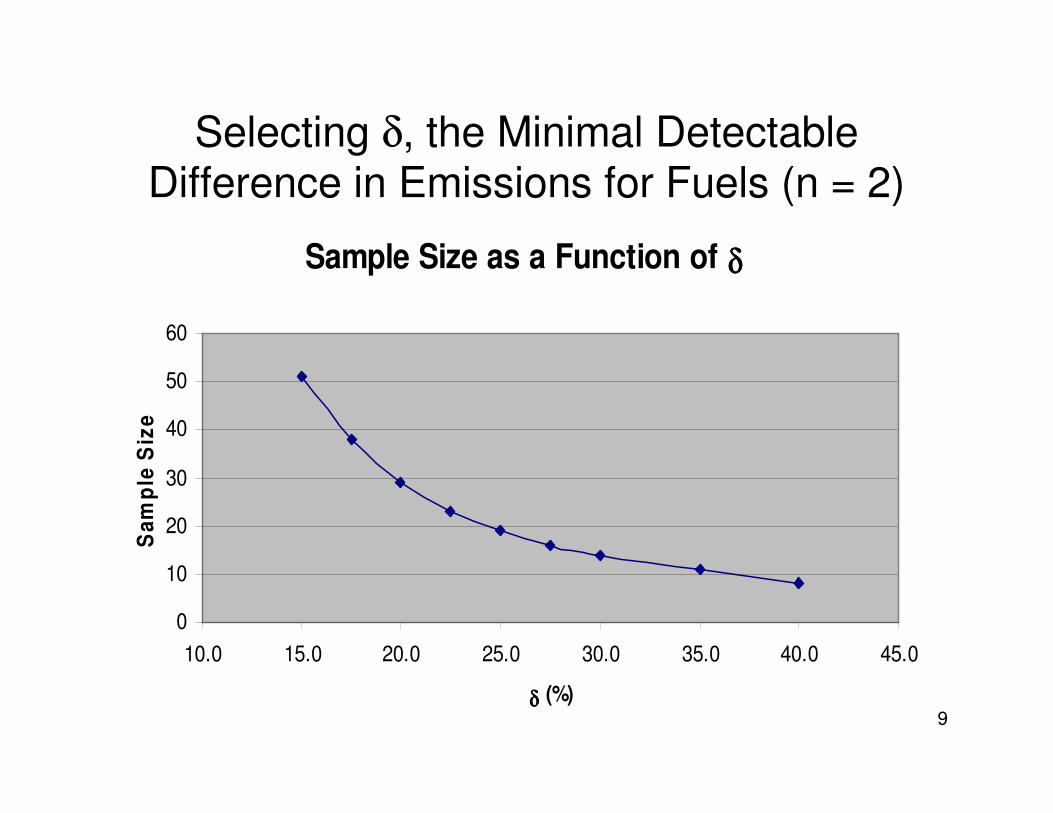
9
Selecting δ, the Minimal Detectable Difference in Emissions for Fuels (n = 2)
Sample Size as a Function of δ δ δ δ
0
10
20
30
40
50
60
10.0 15.0 20.0 25.0 30.0 35.0 40.0 45.0
δ δ δ δ (%)
Sa
mp
le S
ize
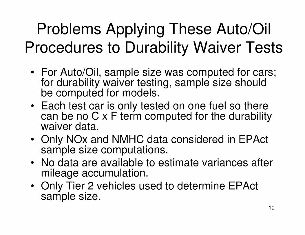
10
Problems Applying These Auto/Oil
Procedures to Durability Waiver Tests
• For Auto/Oil, sample size was computed for cars; for durability waiver testing, sample size should be computed for models.
• Each test car is only tested on one fuel so there can be no C x F term computed for the durability waiver data.
• Only NOx and NMHC data considered in EPActsample size computations.
• No data are available to estimate variances after mileage accumulation.
• Only Tier 2 vehicles used to determine EPActsample size.
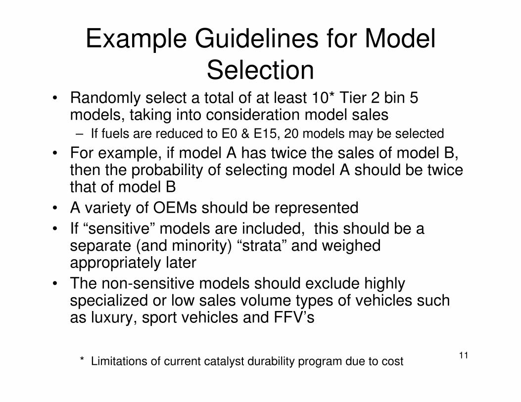
11
Example Guidelines for Model
Selection• Randomly select a total of at least 10* Tier 2 bin 5
models, taking into consideration model sales – If fuels are reduced to E0 & E15, 20 models may be selected
• For example, if model A has twice the sales of model B, then the probability of selecting model A should be twice that of model B
• A variety of OEMs should be represented
• If “sensitive” models are included, this should be a separate (and minority) “strata” and weighed appropriately later
• The non-sensitive models should exclude highly specialized or low sales volume types of vehicles such as luxury, sport vehicles and FFV’s
* Limitations of current catalyst durability program due to cost
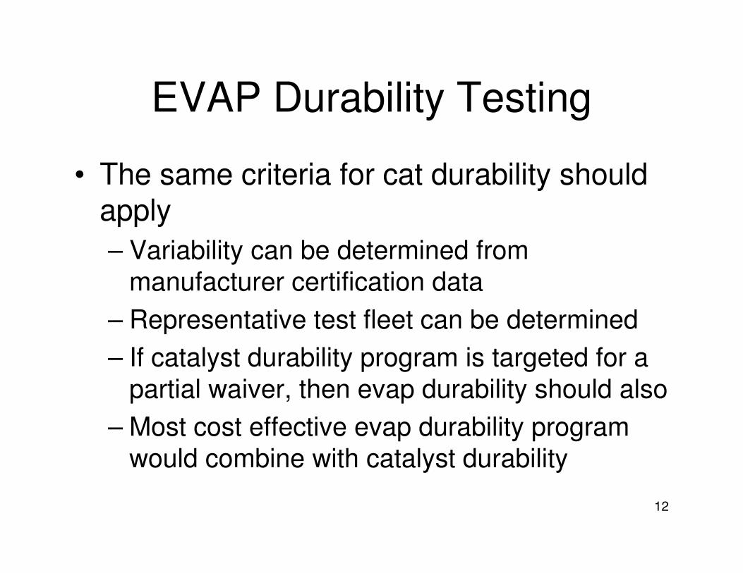
12
EVAP Durability Testing
• The same criteria for cat durability should apply
– Variability can be determined from
manufacturer certification data
– Representative test fleet can be determined
– If catalyst durability program is targeted for a
partial waiver, then evap durability should also
– Most cost effective evap durability program
would combine with catalyst durability
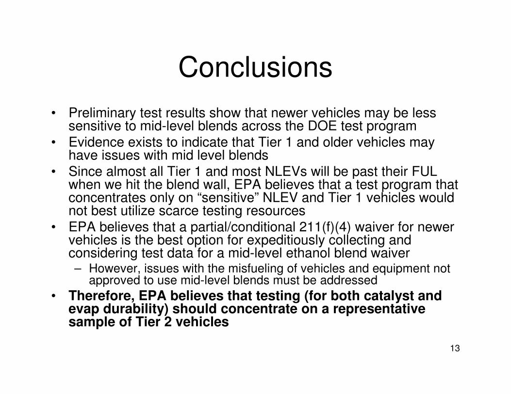
13
Conclusions
• Preliminary test results show that newer vehicles may be less sensitive to mid-level blends across the DOE test program
• Evidence exists to indicate that Tier 1 and older vehicles may have issues with mid level blends
• Since almost all Tier 1 and most NLEVs will be past their FUL when we hit the blend wall, EPA believes that a test program that concentrates only on “sensitive” NLEV and Tier 1 vehicles would not best utilize scarce testing resources
• EPA believes that a partial/conditional 211(f)(4) waiver for newer vehicles is the best option for expeditiously collecting and considering test data for a mid-level ethanol blend waiver– However, issues with the misfueling of vehicles and equipment not
approved to use mid-level blends must be addressed
• Therefore, EPA believes that testing (for both catalyst and
evap durability) should concentrate on a representative
sample of Tier 2 vehicles
DC01/GUERW/386592.1
EXHIBIT LIST IN
COMMENTS OF
ALLIANCE FOR A SAFE
ALTERNATIVE FUELS ENVIRONMENT (ALLSAFE)
AND
THE OUTDOOR POWER EQUIPMENT INSTITUTE (OPEI)
Notice of Receipt of a: ) Docket ID No.:
Clean Air Act Waiver Application ) EPA-HQ-OAR- 2009-0211
To Increase the Allowable Ethanol ) FRL–8894–5
Content of Gasoline to 15 Percent ) 74 Fed. Reg. 18228 (April 21, 2009)
EXHIBIT A Sahu Technical Study
EXHIBIT B Supplemental Statutory Appendix
EXHIBIT C Briggs Study on E20
EXHIBIT D Sahu Minn Compatibility Study
EXHIBIT E Sahu’s DOE Critique
EXHIBIT F Two Cert. Applications
EXHIBIT G OPEI Test Program
EXHIBIT H EMA Test Plan
EXHIBIT I Karl Simon Presentation