Embed Size (px)
Citation preview
14 RENR7458-09Disassembly and Assembly Section
i02228217
Exhaust Manifold - Removeand InstallSMCS Code: 1059-010
Removal Procedure
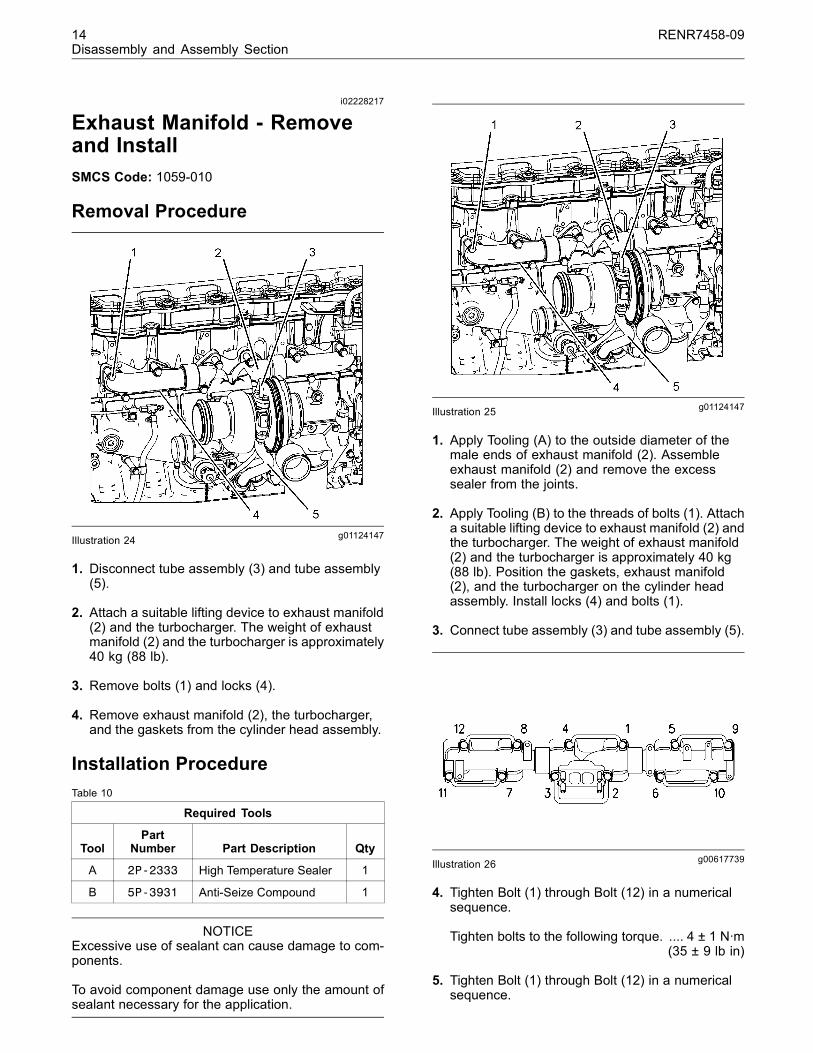
g01124147Illustration 24
1. Disconnect tube assembly (3) and tube assembly(5).
2. Attach a suitable lifting device to exhaust manifold(2) and the turbocharger. The weight of exhaustmanifold (2) and the turbocharger is approximately40 kg (88 lb).
3. Remove bolts (1) and locks (4).
4. Remove exhaust manifold (2), the turbocharger,and the gaskets from the cylinder head assembly.
Installation ProcedureTable 10
Required Tools
ToolPart
Number Part Description Qty
A 2P-2333 High Temperature Sealer 1
B 5P-3931 Anti-Seize Compound 1
NOTICEExcessive use of sealant can cause damage to com-ponents.
To avoid component damage use only the amount ofsealant necessary for the application.
g01124147Illustration 25
1. Apply Tooling (A) to the outside diameter of themale ends of exhaust manifold (2). Assembleexhaust manifold (2) and remove the excesssealer from the joints.
2. Apply Tooling (B) to the threads of bolts (1). Attacha suitable lifting device to exhaust manifold (2) andthe turbocharger. The weight of exhaust manifold(2) and the turbocharger is approximately 40 kg(88 lb). Position the gaskets, exhaust manifold(2), and the turbocharger on the cylinder headassembly. Install locks (4) and bolts (1).
3. Connect tube assembly (3) and tube assembly (5).
g00617739Illustration 26
4. Tighten Bolt (1) through Bolt (12) in a numericalsequence.
Tighten bolts to the following torque. .... 4 ± 1 N·m(35 ± 9 lb in)
5. Tighten Bolt (1) through Bolt (12) in a numericalsequence.
RENR7458-09 15Disassembly and Assembly Section
Tighten bolts to the following torque. .. 45 ± 5 N·m(33 ± 4 lb ft)
6. Bend the locking tab over the flat of each bolthead.
Note: Prior to starting or running the engine, allowthe sealant in the exhaust manifold joints to air dryfor 24 hours.
i02228257
Air Inlet Heater Solenoid -Remove and InstallSMCS Code: 1090-010-OD
Removal Procedure
Disconnect batteries before performance of anyservice work.
1. Disconnect the battery. Refer to Operation andMaintenance Manual, “Battery or Battery Cable- Disconnect”.
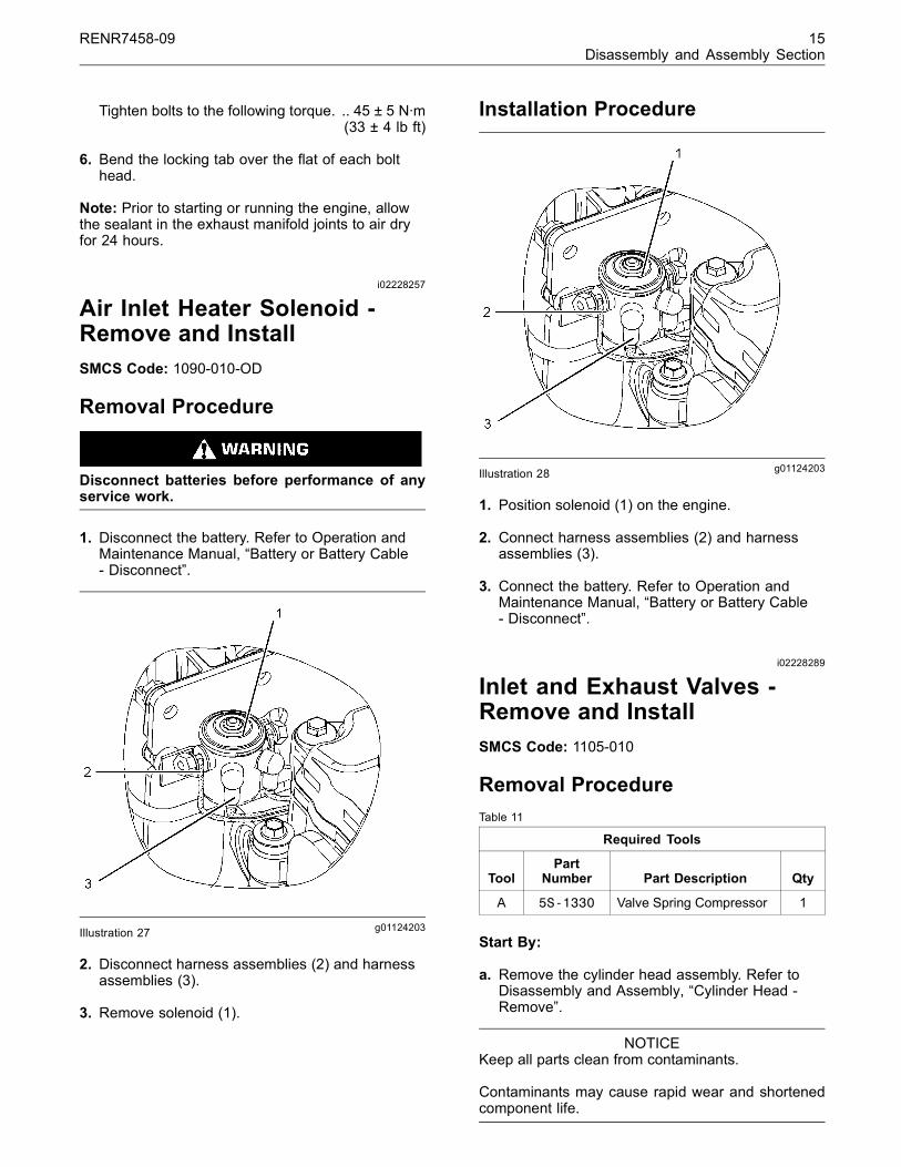
g01124203Illustration 27
2. Disconnect harness assemblies (2) and harnessassemblies (3).
3. Remove solenoid (1).
Installation Procedure
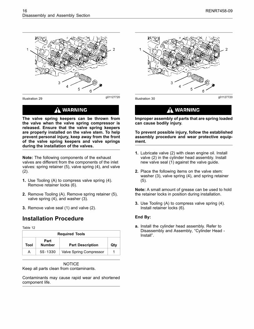
g01124203Illustration 28
1. Position solenoid (1) on the engine.
2. Connect harness assemblies (2) and harnessassemblies (3).
3. Connect the battery. Refer to Operation andMaintenance Manual, “Battery or Battery Cable- Disconnect”.
i02228289
Inlet and Exhaust Valves -Remove and InstallSMCS Code: 1105-010
Removal ProcedureTable 11
Required Tools
ToolPart
Number Part Description Qty
A 5S-1330 Valve Spring Compressor 1
Start By:
a. Remove the cylinder head assembly. Refer toDisassembly and Assembly, “Cylinder Head -Remove”.
NOTICEKeep all parts clean from contaminants.
Contaminants may cause rapid wear and shortenedcomponent life.
16 RENR7458-09Disassembly and Assembly Section
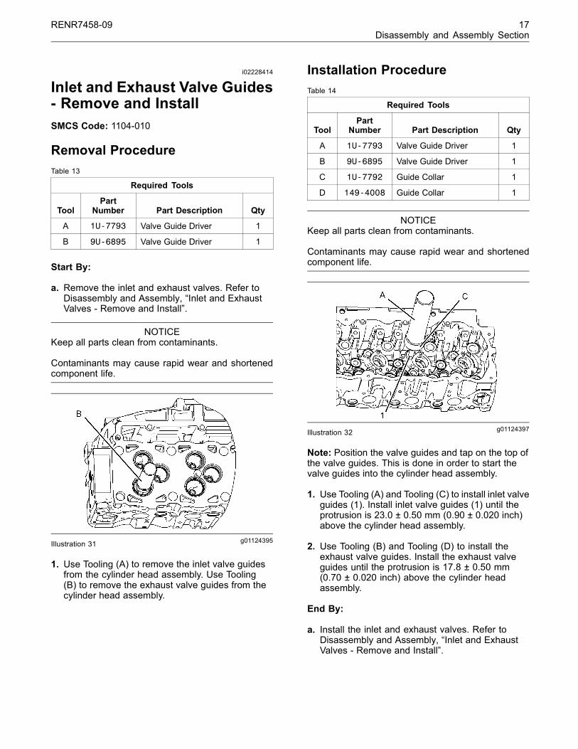
g01127720Illustration 29
The valve spring keepers can be thrown fromthe valve when the valve spring compressor isreleased. Ensure that the valve spring keepersare properly installed on the valve stem. To helpprevent personal injury, keep away from the frontof the valve spring keepers and valve springsduring the installation of the valves.
Note: The following components of the exhaustvalves are different from the components of the inletvalves: spring retainer (5), valve spring (4), and valve(2).
1. Use Tooling (A) to compress valve spring (4).Remove retainer locks (6).
2. Remove Tooling (A). Remove spring retainer (5),valve spring (4), and washer (3).
3. Remove valve seal (1) and valve (2).
Installation ProcedureTable 12
Required Tools
ToolPart
Number Part Description Qty
A 5S-1330 Valve Spring Compressor 1
NOTICEKeep all parts clean from contaminants.
Contaminants may cause rapid wear and shortenedcomponent life.
g01127720Illustration 30
Improper assembly of parts that are spring loadedcan cause bodily injury.
To prevent possible injury, follow the establishedassembly procedure and wear protective equip-ment.
1. Lubricate valve (2) with clean engine oil. Installvalve (2) in the cylinder head assembly. Installnew valve seal (1) against the valve guide.
2. Place the following items on the valve stem:washer (3), valve spring (4), and spring retainer(5).
Note: A small amount of grease can be used to holdthe retainer locks in position during installation.
3. Use Tooling (A) to compress valve spring (4).Install retainer locks (6).
End By:
a. Install the cylinder head assembly. Refer toDisassembly and Assembly, “Cylinder Head -Install”.
RENR7458-09 17Disassembly and Assembly Section
i02228414
Inlet and Exhaust Valve Guides- Remove and InstallSMCS Code: 1104-010
Removal ProcedureTable 13
Required Tools
ToolPart
Number Part Description Qty
A 1U-7793 Valve Guide Driver 1
B 9U-6895 Valve Guide Driver 1
Start By:
a. Remove the inlet and exhaust valves. Refer toDisassembly and Assembly, “Inlet and ExhaustValves - Remove and Install”.
NOTICEKeep all parts clean from contaminants.
Contaminants may cause rapid wear and shortenedcomponent life.
g01124395Illustration 31
1. Use Tooling (A) to remove the inlet valve guidesfrom the cylinder head assembly. Use Tooling(B) to remove the exhaust valve guides from thecylinder head assembly.
Installation ProcedureTable 14
Required Tools
ToolPart
Number Part Description Qty
A 1U-7793 Valve Guide Driver 1
B 9U-6895 Valve Guide Driver 1
C 1U-7792 Guide Collar 1
D 149-4008 Guide Collar 1
NOTICEKeep all parts clean from contaminants.
Contaminants may cause rapid wear and shortenedcomponent life.
g01124397Illustration 32
Note: Position the valve guides and tap on the top ofthe valve guides. This is done in order to start thevalve guides into the cylinder head assembly.
1. Use Tooling (A) and Tooling (C) to install inlet valveguides (1). Install inlet valve guides (1) until theprotrusion is 23.0 ± 0.50 mm (0.90 ± 0.020 inch)above the cylinder head assembly.
2. Use Tooling (B) and Tooling (D) to install theexhaust valve guides. Install the exhaust valveguides until the protrusion is 17.8 ± 0.50 mm(0.70 ± 0.020 inch) above the cylinder headassembly.
End By:
a. Install the inlet and exhaust valves. Refer toDisassembly and Assembly, “Inlet and ExhaustValves - Remove and Install”.

18 RENR7458-09Disassembly and Assembly Section
i02954230
Inlet and Exhaust Valve SeatInserts - Remove and InstallSMCS Code: 1103-010
Removal ProcedureTable 15
Required Tools
ToolPart
Number Part Description Qty
6V-4194 Valve Seat Extractor(2) 1
165-5647 Valve Seat Extractor(3) 1
6V-4804 Handle 1
6V-4192 Shaft 1
A(1)
6V-4199 Lifting Bracket 1(1) Part of the 166-7441 Valve Seat Extractor Tool Group(2) Use for removal of the exhaust valve seats(3) Use for removal of the inlet valve seats
Start By:
a. Remove the inlet and exhaust valves. Refer toDisassembly and Assembly, “Inlet and ExhaustValves - Remove and Install”.
NOTICEKeep all parts clean from contaminants.
Contaminants may cause rapid wear and shortenedcomponent life.
g01124436Illustration 33
1. Use Tooling (A) to remove valve seat inserts (1).
Installation ProcedureTable 16
Required Tools
ToolPart
Number Part Description Qty
149-6115 Installer 1B
133-9306 Valve Guide 1
NOTICEKeep all parts clean from contaminants.
Contaminants may cause rapid wear and shortenedcomponent life.
g01475612Illustration 34
1. Lower the temperature of new valve seat inserts(1).
2. Use Tooling (B) and a suitable press to install thenew valve seat inserts in the cylinder head.
Note: Do not machine the prefinished valve seatinserts in order to correct the valve stem projection.An excessive valve stem projection indicates that thevalve seat insert is not seated or material was notcleaned from the bottom of the counterbore.
End By:
a. Install the inlet valves and exhaust valves. Referto Disassembly and Assembly, “Inlet and ExhaustValves - Remove and Install”.
RENR7458-09 19Disassembly and Assembly Section
i02519791
Engine Oil Filter Base and OilCooler - RemoveSMCS Code: 1306-011; 1378-012
Removal ProcedureTable 17
Required Tools
ToolPart
Number Part Description Qty
A 185-3630 Strap Wrench Assembly 1
NOTICECare must be taken to ensure that fluids are containedduring performance of inspection, maintenance, test-ing, adjusting and repair of the product. Be prepared tocollect the fluid with suitable containers before open-ing any compartment or disassembling any compo-nent containing fluids.
Refer to Special Publication, NENG2500, “CaterpillarTools and Shop Products Guide” for tools and suppliessuitable to collect and contain fluids on Caterpillarproducts.
Dispose of all fluids according to local regulations andmandates.
1. Drain the coolant system. Refer to Operationand Maintenance Manual, “Refill Capacities andRecommendations”.
g01261004Illustration 35
2. Remove nuts (1). Remove bracket (2) and thehose assembly. Use Tooling (A) and remove oilfilter (3).
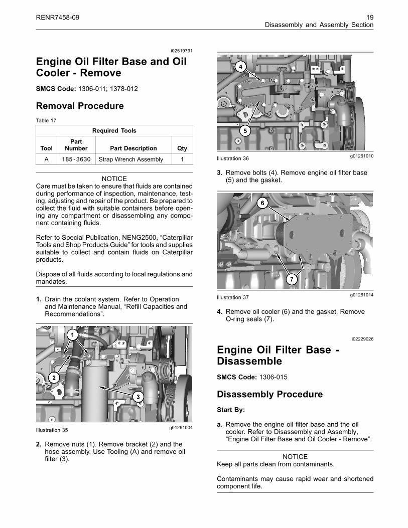
g01261010Illustration 36
3. Remove bolts (4). Remove engine oil filter base(5) and the gasket.
g01261014Illustration 37
4. Remove oil cooler (6) and the gasket. RemoveO-ring seals (7).
i02229026
Engine Oil Filter Base -DisassembleSMCS Code: 1306-015
Disassembly ProcedureStart By:
a. Remove the engine oil filter base and the oilcooler. Refer to Disassembly and Assembly,“Engine Oil Filter Base and Oil Cooler - Remove”.
NOTICEKeep all parts clean from contaminants.
Contaminants may cause rapid wear and shortenedcomponent life.
20 RENR7458-09Disassembly and Assembly Section
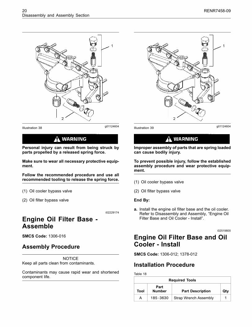
g01124604Illustration 38
Personal injury can result from being struck byparts propelled by a released spring force.
Make sure to wear all necessary protective equip-ment.
Follow the recommended procedure and use allrecommended tooling to release the spring force.
(1) Oil cooler bypass valve
(2) Oil filter bypass valve
i02229174
Engine Oil Filter Base -AssembleSMCS Code: 1306-016
Assembly Procedure
NOTICEKeep all parts clean from contaminants.
Contaminants may cause rapid wear and shortenedcomponent life.
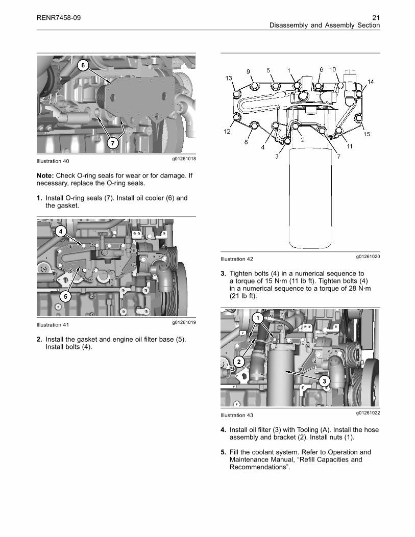
g01124604Illustration 39
Improper assembly of parts that are spring loadedcan cause bodily injury.
To prevent possible injury, follow the establishedassembly procedure and wear protective equip-ment.
(1) Oil cooler bypass valve
(2) Oil filter bypass valve
End By:
a. Install the engine oil filter base and the oil cooler.Refer to Disassembly and Assembly, “Engine OilFilter Base and Oil Cooler - Install”.
i02519800
Engine Oil Filter Base and OilCooler - InstallSMCS Code: 1306-012; 1378-012
Installation ProcedureTable 18
Required Tools
ToolPart
Number Part Description Qty
A 185-3630 Strap Wrench Assembly 1
RENR7458-09 21Disassembly and Assembly Section
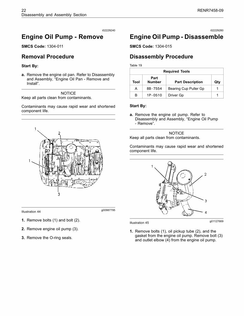
g01261018Illustration 40
Note: Check O-ring seals for wear or for damage. Ifnecessary, replace the O-ring seals.
1. Install O-ring seals (7). Install oil cooler (6) andthe gasket.
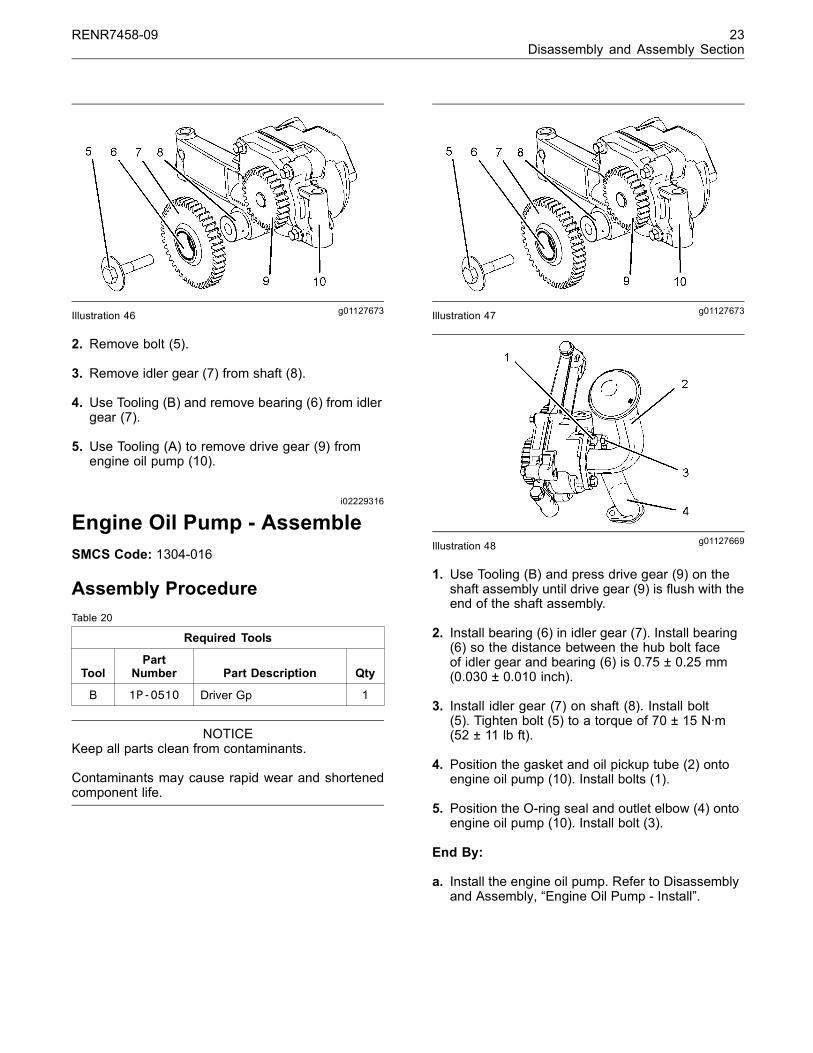
g01261019Illustration 41
2. Install the gasket and engine oil filter base (5).Install bolts (4).
g01261020Illustration 42
3. Tighten bolts (4) in a numerical sequence toa torque of 15 N·m (11 lb ft). Tighten bolts (4)in a numerical sequence to a torque of 28 N·m(21 lb ft).
g01261022Illustration 43
4. Install oil filter (3) with Tooling (A). Install the hoseassembly and bracket (2). Install nuts (1).
5. Fill the coolant system. Refer to Operation andMaintenance Manual, “Refill Capacities andRecommendations”.
22 RENR7458-09Disassembly and Assembly Section
i02229240
Engine Oil Pump - RemoveSMCS Code: 1304-011
Removal ProcedureStart By:
a. Remove the engine oil pan. Refer to Disassemblyand Assembly, “Engine Oil Pan - Remove andInstall”.
NOTICEKeep all parts clean from contaminants.
Contaminants may cause rapid wear and shortenedcomponent life.
g00987795Illustration 44
1. Remove bolts (1) and bolt (2).
2. Remove engine oil pump (3).
3. Remove the O-ring seals.
i02229280
Engine Oil Pump - DisassembleSMCS Code: 1304-015
Disassembly ProcedureTable 19
Required Tools
ToolPart
Number Part Description Qty
A 8B-7554 Bearing Cup Puller Gp 1
B 1P-0510 Driver Gp 1
Start By:
a. Remove the engine oil pump. Refer toDisassembly and Assembly, “Engine Oil Pump- Remove”.
NOTICEKeep all parts clean from contaminants.
Contaminants may cause rapid wear and shortenedcomponent life.
g01127669Illustration 45
1. Remove bolts (1), oil pickup tube (2), and thegasket from the engine oil pump. Remove bolt (3)and outlet elbow (4) from the engine oil pump.
RENR7458-09 23Disassembly and Assembly Section
g01127673Illustration 46
2. Remove bolt (5).
3. Remove idler gear (7) from shaft (8).
4. Use Tooling (B) and remove bearing (6) from idlergear (7).
5. Use Tooling (A) to remove drive gear (9) fromengine oil pump (10).
i02229316
Engine Oil Pump - AssembleSMCS Code: 1304-016
Assembly ProcedureTable 20
Required Tools
ToolPart
Number Part Description Qty
B 1P-0510 Driver Gp 1
NOTICEKeep all parts clean from contaminants.
Contaminants may cause rapid wear and shortenedcomponent life.
g01127673Illustration 47
g01127669Illustration 48
1. Use Tooling (B) and press drive gear (9) on theshaft assembly until drive gear (9) is flush with theend of the shaft assembly.
2. Install bearing (6) in idler gear (7). Install bearing(6) so the distance between the hub bolt faceof idler gear and bearing (6) is 0.75 ± 0.25 mm(0.030 ± 0.010 inch).
3. Install idler gear (7) on shaft (8). Install bolt(5). Tighten bolt (5) to a torque of 70 ± 15 N·m(52 ± 11 lb ft).
4. Position the gasket and oil pickup tube (2) ontoengine oil pump (10). Install bolts (1).
5. Position the O-ring seal and outlet elbow (4) ontoengine oil pump (10). Install bolt (3).
End By:
a. Install the engine oil pump. Refer to Disassemblyand Assembly, “Engine Oil Pump - Install”.
24 RENR7458-09Disassembly and Assembly Section
i02229347
Engine Oil Pump - InstallSMCS Code: 1304-012
Installation Procedure
NOTICEKeep all parts clean from contaminants.
Contaminants may cause rapid wear and shortenedcomponent life.
g00987795Illustration 49
1. Install the O-ring seals. Position engine oil pump(3) on the cylinder block.
2. Install bolts (1) and bolt (2).
End By:
a. Install the engine oil pan. Refer to Disassemblyand Assembly, “Engine Oil Pan - Remove andInstall”.
i02229479
Water Pump - RemoveSMCS Code: 1361-011
Removal ProcedureStart By:
a. Remove the alternator. Refer to Disassembly andAssembly, “Alternator - Remove and Install”.
NOTICEKeep all parts clean from contaminants.
Contaminants may cause rapid wear and shortenedcomponent life.
NOTICECare must be taken to ensure that fluids are containedduring performance of inspection, maintenance, test-ing, adjusting and repair of the product. Be prepared tocollect the fluid with suitable containers before open-ing any compartment or disassembling any compo-nent containing fluids.
Refer to Special Publication, NENG2500, “CaterpillarTools and Shop Products Guide” for tools and suppliessuitable to collect and contain fluids on Caterpillarproducts.
Dispose of all fluids according to local regulations andmandates.
1. Drain the coolant system. Refer to Operationand Maintenance Manual, “Refill Capacities andRecommendations”.
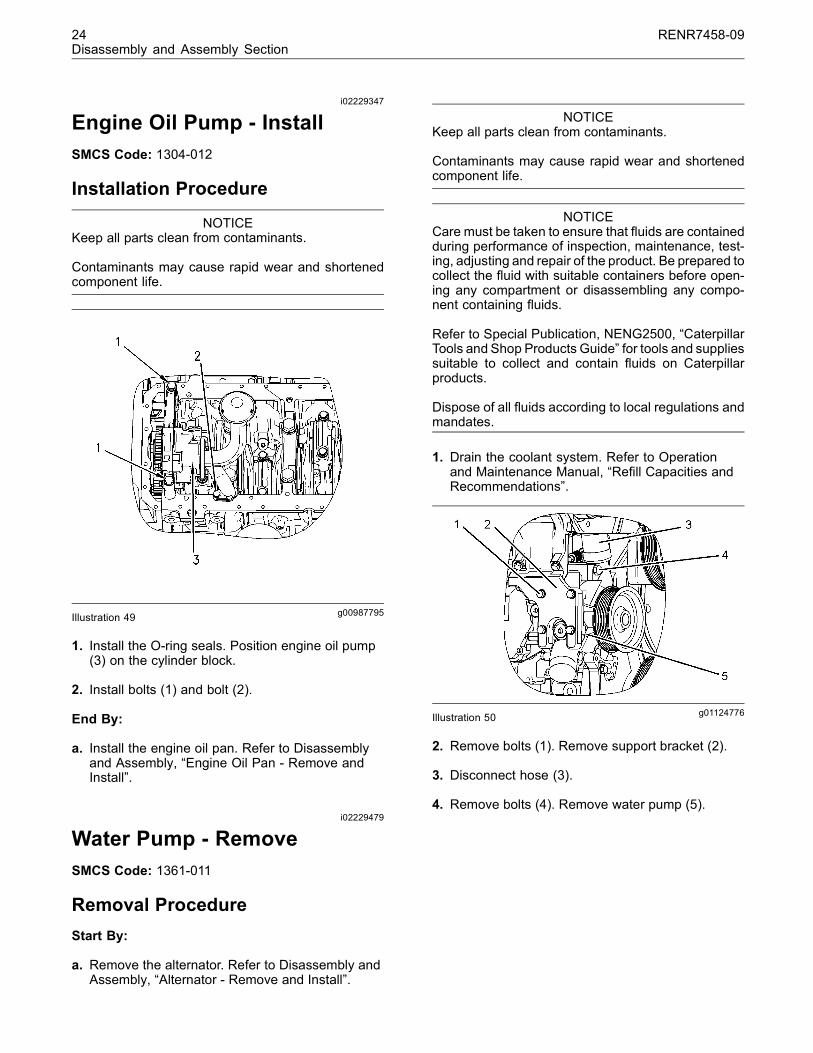
g01124776Illustration 50
2. Remove bolts (1). Remove support bracket (2).
3. Disconnect hose (3).
4. Remove bolts (4). Remove water pump (5).