Embed Size (px)
Citation preview

LO W I M PA C T D E V E LO P M E N T P L A N N I N G A N D D E S I G N FA C T S H E E T
DESIGN
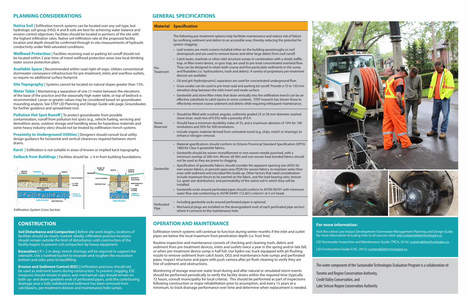
GEOMETRY AND SITE LAYOUTSystems should be located parallel with conventional storm sewers, typically below roads or landscape areas where they can be easily accessed for inspection, maintenance and repair by maintenance holes. Gravel trenches in which the perforated pipes are installed are typically rectangular excavations with a bottom width between 0.6 and 2.4 metres. The gravel trenches should have gentle slopes between 0.5 to 1%. Typically designed with an impervious drainage area to pervious facility footprint area ratio (I:P ratio) of between 15:1 to 20:1.
INLETSInlets may include plastic or concrete pipes from roof drains or catch basins, storm sewers, oil and grit separators (OGS) or outlet leader from an upstream best management practice (BMP).
PRE-TREATMENT It is important to prevent sediment, trash and debris from entering infiltration facilities because they could contribute to clogging and failure of the system. Exfiltration trench systems may be used to treat runoff from roofs, walkways, parking lots and roads with sedimentation or filtration pre-treatment.
STONE RESERVOIRDepth below the invert of the perforated pipe must meet both runoff storage and structural support requirements. See STEP LID Planning and Design Guide wiki page, Infiltration: Sizing and modelling, for guidance and spreadsheet tool for determining the reservoir depth and area required to store the design storm runoff volume. See Specifications for further details.
GEOTEXTILEStorage reservoirs should be lined on the sides and top with geotextile filter fabric to maintain separation from the native soil. Geotextile on the base is optional but may be prone to blinding and eventual clogging.
PERFORATED PIPEContinuously perforated, smooth interior HDPE or PVC drainage pipe, ≥200 mm interior diameter where possible to reduce risk of freezing and facilitate push camera inspection and cleaning with jet nozzle equipment. Dimension and configuration of perforations should not restrict flow of stormwater into the trench during the design storm event. See STEP LID Planning and Design Guide wiki page, Flow through perforated pipe, for guidance on estimating maximum flow rate through a perforated pipe.
CONVEYANCE AND OVERFLOWCollection and conveyance of runoff into the exfiltration trench system can be accomplished through conventional catch basins and non-perforated pipes leading from foundation drains and roof downspouts. Conveyance of road runoff may also occur through curb cuts and swales with regularly spaced catch basins or geotextile and stone filter inlets that drain captured runoff to the trench below. The gravel filled trench should be 75 to 150 mm deep above the perforated pipe. Trench plugs installed at regular intervals reduce downstream migration of granular material and enhance infiltration by preventing conveyance of water to the downstream end of the trench. Overflows from the granular filled trench back up into maintenance holes connected to conventional storm sewers. The overflow outlet storm sewer should be below the maximum frost penetration depth (i.e. frost line) to function year-round.
ACCESS STRUCTURESTypically maintenance holes provide access to perforated pipes for periodic inspection and jet nozzle cleaning. Maintenance holes may also be used for drainage time monitoring.
BMPAbility to meet stormwater criteria
Water balance Water quality Stream erosion control
Exfiltration Trench Systems Yes Yes Yes
Perforated Pipe System
Exfiltration Trench Systems Exfiltration Trench Systems (also known as perforated pipe systems, clean water collectors, or percolation drainage systems) are infiltration trenches integrated with conventional stormwater conveyance systems (i.e. catch basins, pipes and maintenance holes) and designed for both conveyance and infiltration functions. They are composed of perforated pipes, capped on down-gradient ends, installed in gently sloping gravel-filled trenches containing trench plugs and may be wrapped with geotextile filter fabric. They allow exfiltration of runoff into the gravel trench, and infiltration into the underlying native soil while it is being conveyed. Systems may include perforated catch basin and maintenance hole risers. Exfiltration trench systems can be used in conjunction with, or in place of conventional storm sewer pipes, where topography, water table depth and runoff quality conditions are suitable. They are recommended for treating runoff from roofs, walkways, parking lots and roads, with adequate pre-treatment.
Trench Construction
PLANNING CONSIDERATIONS
Native Soil | Exfiltration trench systems can be located over any soil type, but hydrologic soil group (HSG) A and B soils are best for achieving water balance and erosion control objectives. Facilities should be located in portions of the site with the highest infiltration rates. Native soil infiltration rate at the proposed facility location and depth should be confirmed through in-situ measurements of hydraulic conductivity under field saturated conditions.
Wellhead Protection | Facilities receiving road or parking lot runoff should not be located within 2 year time-of-travel wellhead protection areas (see local drinking water source protection plan).
Available Space | Recommended within road right-of-ways. Utilizes conventional stormwater conveyance infrastructure for pre-treatment, inlets and overflow outlets, so require no additional surface footprint.
Site Topography | Systems cannot be located on natural slopes greater than 15%.
Water Table | Maintaining a separation of one (1) metre between the elevations of the base of the practice and the seasonally high water table, or top of bedrock is recommended. Lesser or greater values may be considered based on groundwater mounding analysis. See STEP LID Planning and Design Guide wiki page, Groundwater, for further guidance and spreadsheet tool.
Pollution Hot Spot Runoff | To protect groundwater from possible contamination, runoff from pollution hot spots (e.g., vehicle fueling, servicing and demolition areas, outdoor storage and handling areas for hazardous materials and some heavy industry sites) should not be treated by exfiltration trench systems.
Proximity to Underground Utilities | Designers should consult local utility design guidance for horizontal and vertical clearances required between storm drains.
Karst | Exfiltration is not suitable in areas of known or implied karst topography.
Setback from Buildings | Facilities should be ≥ 4 m from building foundations.
CONSTRUCTION Soil Disturbance and Compaction | Before site work begins, locations of facilities should be clearly marked. Ideally, infiltration practice locations should remain outside the limit of disturbance until construction of the facility begins to prevent soil compaction by heavy equipment.
Excavation | If > 2 m deep, trench shorings will be required to support the sidewalls. Use a toothed bucket to excavate and roughen the excavation bottom and sides prior to backfilling.
Erosion and Sediment Control (ESC) | Infiltration practices should not be used as sediment basins during construction. To prevent clogging, ESC measures should remain in place, and mechanical caps should remain on both up- and down-gradient ends of perforated pipes, until the contributing drainage area is fully stabilized and sediment has been removed from catchbasins, pre-treatment devices and maintenance hole sumps.
Material Specification
Pre-Treatment
The following pre-treatment options help facilitate maintenance and reduce risk of failure by confining sediment and debris to an accessible area, thereby reducing the potential for system clogging:
• Leaf screens are mesh screens installed either on the building eavestroughs or roof downspouts and are used to remove leaves and other large debris from roof runoff.
• Catch basin, manhole or other inlet structure sumps in combination with a shield, baffle, trap, or filter insert device, or goss trap, are used to pre-treat concentrated overland flow. They can be designed to retain both coarse and fine particulate sediments in the sump, and floatables (i.e. hydrocarbons, trash and debris). A variety of proprietary pre-treatment devices are available.
• Oil and grit (hydrodynamic) separators are used for concentrated underground flow.
• Grass swales can be used to pre-treat road and parking lot runoff. Provide a 75 to 150 mm elevation drop between the inlet invert and swale surface.
• Geotextile and stone filter inlets that drain vertically into the exfiltration trench can be an effective substitute to catch basins in some contexts. STEP research has shown these to effectively remove coarse sediment and debris while requiring infrequent maintenance.
Stone Reservoir
• Should be filled with crushed, angular, uniformly graded 25 or 50 mm diameter washed stone (max. wash loss of 0.5%) with a porosity of 0.4.
• Should have a minimum durability index of 35, and a maximum abrasion of 10% for 100 revolutions and 50% for 500 revolutions.
• Include organic material derived from untreated wood (e.g. chips, mulch or shavings) to enhance nitrogen removal.
Geotextile
• Material specifications should conform to Ontario Provincial Standard Specification (OPSS) 1860 for Class II geotextile fabrics.
• Geotextile should be woven monofilament or non-woven needle punched, with a minimum overlap of 300 mm. Woven slit film and non-woven heat bonded fabrics should not be used as they are prone to clogging.
• Specification of geotextile fabrics should consider the apparent opening size (AOS) for non-woven fabrics, or percent open area (POA) for woven fabrics, to maintain water flow even with sediment and microbial film build-up. Other factors that need consideration include maximum forces to be exerted on the fabric, and the load bearing ratio, texture (i.e. grain size distribution), and permeability of the native soil in which they will be installed.
• Geotextile socks around perforated pipes should conform to ASTM D6707 with minimum water flow rate conforming to ASTM D4491 (12,263 L/min/m2 at 5 cm head).
Perforated Pipe
• Including geotextile socks around perforated pipes is optional. • Mechanical plugs are installed on the downgradient ends of each perforated pipe section
where it connects to the maintenance hole.
GENERAL SPECIFICATIONS
The water component of the Sustainable Technologies Evaluation Program is a collaboration of:
Toronto and Region Conservation Authority,Credit Valley Conservation, andLake Simcoe Region Conservation Authority
For more information:
Visit the online Low Impact Development Stormwater Management Planning and Design Guide for more information including links to all sources cited: wiki.sustainabletechnologies.ca.
LID Stormwater Inspection and Maintenance Guide (TRCA, 2016): sustainabletechnologies.ca.
LID Construction Guide (CVC, 2012): sustainabletechnologies.ca.
OPERATION AND MAINTENANCE Exfiltration trench systems will continue to function during winter months if the inlet and outlet pipes are below the local maximum frost penetration depth (i.e. frost line).
Routine inspection and maintenance consists of checking and cleaning trash, debris and sediment from pre-treatment devices, inlets and outlets twice a year in the spring and/or late fall, or when pre-treatment device sump is half full. Use hydro-vac truck equipped with jet flushing nozzle to remove sediment from catch basin, OGS and maintenance hole sumps and perforated pipes. Inspect structures and pipes with push camera after jet flush cleaning to verify they are free of sediment and obstructions.
Monitoring of storage reservoir water level during and after natural or simulated storm events should be performed periodically to verify the facility drains within the required time (typically 72 hours, consult municipality for local criteria). This should be performed as part of inspections following construction or major rehabilitation prior to assumption, and every 15 years at a minimum, to track drainage performance over time and determine when replacement is needed.
Exfiltration System Cross Section