Embed Size (px)
Citation preview
Int. J. Exergy, Vol. 32, No. 2, 2020 103
Copyright © 2020 Inderscience Enterprises Ltd.
Exergy analysis of district energy systems and comparison of their exergetic, energetic and environmental performance
Ehsan Ahmadian* School of Architecture and the Built Environment, University of Lincoln, Lincoln, LN6 7TS, UK Email: [email protected] *Corresponding author
Ralf-Roman Schmidt Center for Energy, Austrian Institute of Technology, Giefinggasse 6, 1210 Vienna, Austria Email: [email protected]
Abstract: This paper investigates the advantages of performing exergy analysis for thermodynamic systems consisting of a district heating network (DHN) by comparing the exergy performance with energetic and environmental performance of three case studies in Austria. Furthermore, the effect of influential parameters such as energy source type, conversion technology, supply/return temperature and reference temperature on exergy performance of the system was investigated. An initial literature review and analysis of the case studies showed that the most influential factor on exergy performance of a system was the type of energy source and its conversion technology. Although lowering the supply temperature of DHN can increase the exergy efficiency of the system, changing reference temperature did not show a clear relationship with exergy efficiency. Finally, no clear relationship between energy and exergy efficiencies of the system was discovered; nevertheless, the higher the exergy efficiency of a system the lower the direct CO2 emissions from it.
Keywords: exergy analysis; thermodynamic systems; exergy indicators; district heating network; DHN; energy efficiency; CO2 emissions.
Reference to this paper should be made as follows: Ahmadian, E. and Schmidt, R-R. (2020) ‘Exergy analysis of district energy systems and comparison of their exergetic, energetic and environmental performance’, Int. J. Exergy, Vol. 32, No. 2, pp.103–129.
Biographical notes: Ehsan Ahmadian is a PhD researcher at the University of Lincoln, UK. He is working on the topic of ‘energy and urban built form’ which is a collaborative project between the Engineering and Architecture Schools of the university. He is also an Associate Lecturer, who teaches the modules of Energy Policy and Hydro/Ocean Power Generation in undergraduate and postgraduate programs. He previously obtained his MSc in Mechanical Engineering from the Polytechnic University of Turin with
104 E. Ahmadian and R-R. Schmidt
experience of doing research in Austrian Institute of Technology as well as University of Liege focusing on exergy/energy analysis of thermodynamic systems and utilisation of renewable energy sources.
Ralf-Roman Schmidt is a Senior Research Engineer and working at the AIT, where he is responsible for the development and management of national and international projects in the field of district heating and integrated energy systems. His research priorities are decarbonisation strategies and sector coupling, digitisation and flexibility as well as low temperature district heating networks. He holds key positions in international networks (e.g., alternate member of the IEA DHC ExCo for Austria, operating agent of the IEA DHC Annex TS3 and Chair of the District Heating and Cooling and Thermal Energy Storage Technology Panel in the RHC-ETIP). After finishing his studies in process and mechanical engineering at the University of Bremen in 2005 (including a Visiting Researcher position at the University of Alberta), he received his PhD in the field of thermo-fluid dynamics in 2013.
1 Introduction
The energy demand for heating and cooling of buildings and communities is responsible for 30% of global energy consumption and today it is mainly provided by fossil fuels (IEA, 2019). Since fossil fuels are the main cause of greenhouse gas (GHG) emissions, they are responsible for nearly 40% of the total direct and indirect CO2 emissions (IEA, 2017a). Serious action is required to reduce the average energy use per capita by at least 10% using energy-efficient and low-carbon building technologies by 2025 (IEA, 2017b).
According to results of ECBCS Annex 49 (Torio and Schmidt, 2011), there is a great potential for exergy management of building energy systems, which emphasises the necessary basis for exergetic investigations. Exergy is defined as the maximum amount of work can be obtained from different forms of energy (Dincer and Rosen, 2007) that shows the quality of the energy form. Exergy analysis can identify a strategy to find the optimum design and operational structure of a system (Dobrovicescu et al., 2017) and since it takes into account irreversibility in the system, it helps the outcome of theoretical models to be closer to actual models (Gadalla et al., 2010). Therefore, exergy analysis can optimise energy systems by taking into account both quality and quantity of energy. Increasing exergy efficiency of these systems may decrease the consumption of energy that can result in a considerable reduction of environmental pollutions (specifically CO2 emission). It helps to match the exergy level of the source with the exergy level of demand. Energy needed for space heating (SH) and domestic hot water (DHW) applications in buildings is in low temperature, which means that it will contain a low amount of exergy. In an exergy efficient energy system, low quality sources (with low exergy content) should be used for these kinds of applications. Hence, it is crucial to examine the influence of different energy sources on the exergetic performance of building energy systems. Meanwhile, it is important to simultaneously consider the amount of CO2 emission from those energy sources to find a connection between exergy performance and environmental pollution of the system (Rosen, 2002). For example, energy sources such as fossil fuels contain a high amount of exergy and huge amounts of emissions at the same time, while solar energy, which is thermal radiation emitted at the
Exergy analysis of district energy systems and comparison 105
temperature of the sun (approximately 5,800 K), contains much energy and exergy without any direct CO2 emission, though the maximum exergy efficiency of a solar trigeneration system is less than 5% (Zhang et al., 2018).
This study analyses the exergy performance of the process of heat/electricity generation (e.g., power plant), transportation (DHN) and consumption (building), and investigates the advantages of performing exergy analysis for thermodynamic systems consisting of DHN. The work is a participation to the Annex 64 international research project called ‘lowEx communities – optimised performance of community energy supply systems with exergy principles’ developed by IEA-EBC. “The main objective of Annex 64 is to demonstrate the potential of low exergy thinking on a community level as energy and cost-efficient solution in achieving 100% renewable and GHG emission-free energy systems” (Schmidt, 2014). It is an international networking activity aiming to use exergy analysis to optimise urban and community energy systems by matching the exergy content of supply and demand side.
The aim of this study is to investigate the possible relationship between exergy performance of a system with energy and environmental performance, plus identifying the effect of influential parameters namely energy source type, conversion technology, supply/return temperature of DHN and reference temperature on the exergy performance of the system. Finally, a comparison between the performance of district heating (DH) and individual heating (IH) was made.
1.1 Literature overview
In this section, previous relevant studies are reviewed in order to discover the most popular exergy indicators and their application in exergy analysis of thermodynamic systems.
Looking at scientific books and papers about exergy, it was observed that although exergy is not a common indicator when planning or optimising DHN, it is possible to find plenty of different exergy indicators. Some of them are more common, while others have been used by only a few researchers. The most common exergy indicator was exergy efficiency which has been used by almost all researchers. The second popular indicator was exergy destruction which has a basic relationship with exergy efficiency through equation (2). Therefore, having either of these two indicators, the other one can be calculated. Indicators such as exergy rate (Ėx) (Oktay and Dincer, 2009) have occasionally been used. Although they were not usually the main indicators, they were used to obtain the value of most of the common above-mentioned indicators. Other indicators such as relative avoided irreversibility (RAI) (Ertesvag, 2007), exergetic improvement potential (IP) (Van Gool, 1997), specific exergy index (SExI) (Lee, 2001), exergy utilisation rate (Gong and Werner, 2015), exergetic factor (Hepbasli, 2008; Ozgener et al., 2007), total exergy loss reduced to total fuel exergy (Comakli et al., 2004) and energy grade function (R) (Dincer and Rosen, 2007; Hevert and Hevert, 1980) were either used or only mentioned by a few researchers.
Ossebaard et al. (1997) indicated that the exergy efficiency of a system consisting of a DHN and cogeneration power (CHP) plant was about 1.5 times higher than a system composed of CHP and an electric heat pump, but this efficiency is supposed to improve until the year 2030 due to improvement in conversion technologies and lowering the temperature in DHN. A case study analysis by Rosen and Dincer (2005) showed that DH
106 E. Ahmadian and R-R. Schmidt
had 74% exergy efficiency when it was considered as a separated system, while combination of DH with cogeneration plant decreased its exergy efficiency to 34%, and finally a combination of those two with user heating reached exergy efficiency of 31%. A massive amount of exergy was destroyed in a steam power plant mainly due to the combustion and heat transfer in the steam generator (Rosen and Tang, 2008). They concluded that both energy and exergy efficiencies of plant improve by decreasing either the stack-gas temperature or the fraction of excess air. Ertesvag (2007) performed a specific study using an indicator called RAI and concluded that for exergy efficiency values less than 34%, the separated heat and electricity generation plant was exergetically more efficient than CHP plants. The purpose of his study was assessing different indicators for evaluating CHP systems. Favrat et al. (2008) and Ossebaard et al. (1997) both showed that exergy efficiency of DH plant technology (CHP plant plus DHN) was higher than individual boilers. The important advantage of Favrat et al.’s study was comprehensive assessment of the process of heat production, transmission and consumption. They illustrated that exergy efficiency of power plant can sometimes be higher than the rest of the system in case of using hydropower.
Verda and Kona (2012) and Torío et al. (2010) showed lowering the supply temperature of DHN increases its exergy efficiency and consequently that of the whole system. Furthermore, reducing the return temperature of DHN also increases the exergy efficiency of the system. Torío et al. (2010) proved the stronger influence of supply temperature against return temperature, meaning that the change in supply temperature affects the exergy efficiency of the system more than the change in return temperature. Ertesvag (2007) showed that the exergy efficiency of low temperature DH (55/25°C) was about 60% higher than medium temperature DH (80/40°C) due to the lower supply temperature, while energy efficiency improvement was about 8%. Sun et al. (2012) compared a conventional DH system based on CHP with combined heat and power based on absorption cycle and discovered that the latter exhibited higher exergy efficiency due to recovering waste heat with absorption heat pump and decreasing the temperature of the return water. Comakli et al. (2004) analysed a system composed of a primary and secondary network. They changed the supply and return temperature of the primary network from 140° to 180°C and from 105° to 135°C, respectively, and found that exergy loss due to heat loss along with exergy loss in heat exchangers increased when increasing the temperature difference between supply and return water, but exergy loss due to supplied electrical energy to pumps decreased when increasing both supply and return temperature with different trends. Moreover, using an indicator called total exergy loss reduced to total fuel exergy showed that both a low supply temperature as well as a high return temperature leads to less fuel exergy loss percentage. This meant the smaller the temperature difference, the smaller the fuel exergy loss.
According to Favrat et al. (2008), by decreasing the building (radiators) supply/return temperature, exergy efficiency of room convertors as well as the whole system increased, exergy efficiency of the plant of building (substation heat exchanger) slightly decreased, and finally exergy efficiency of DHN did not change. Arslan et al. (2009) indicated that exergy efficiency of a geothermal district heating system (GDHS) reached its maximum by increasing the building heating circuit (radiators) up to the optimum value and then decreased. They concluded that the maximum exergy efficiency was achieved when the difference between building supply and return temperature was 10–15°C.
Exergy analysis of district energy systems and comparison 107
Verda and Kona (2012), Oktay et al. (2008) and Keçebas (2013) all showed that in a GDHS, exergy efficiency of DHN as well as the whole system increased by decreasing outdoor temperature, which was due to the increase of the exergy input potential. On the contrary, Li and Svendsen (2012) indicated that exergy efficiency increased from 8% to 36% for low temperature DH and from 11% to 47% for medium temperature DH by increasing ambient temperature from –9°C to 16°C. Ozgener and Ozgener (2009) showed that both energy and exergy efficiencies in a GDHS with supply/return DHN temperatures of 88/(38–42)°C was maximum when outdoor temperature was maximum and decreased to minimum level when outdoor temperature was minimum. Ünver and Kılıç (2017) demonstrated that decreasing environment temperature from 35°C to 5°C improves the exergy efficiency of a combined cycle power plant (about 5%), but this enhancement changes into reduction if the environment temperature decreases further.
Yabanova and Keçebas (2013) performed a specific analysis in a PID-based control strategy case (which controls flow rates in the system) and a manual case and discovered that exergy efficiency in the controlled case was maintained around the maximum values (with an average efficiency of 29.0%), while the manual operation gave increase and decrease (with an average efficiency of 28.57%). They concluded that exergy analysis is a useful mean for achieving optimum operating condition since analysis of exergy flows of the system can identify the inefficient parts.
Although in purely thermal systems the exergy efficiency cannot be higher than energy efficiency (because there are internal irreversibilities due to thermal gradients), it is sometimes possible to have a system with greater exergy efficiency compared to its energy efficiency (Oktay et al., 2008; Ozgener and Ozgener, 2009; Ozgener et al., 2007). For instance, in the case of electricity production from geothermal energy, the energy efficiency is the ratio of electricity produced and the energy extracted from the ground. But considering exergy efficiency, the product is the same as before (since electricity contains 100% exergy) while the resource is lower (since exergy of geothermal energy is lower than its energy); therefore, the exergy efficiency becomes higher because of a lower denominator.
In general, the exergy efficiency of a CHP plant is not more than 50% in best case, while this value is even less for thermal plants. Passing through the power plant, considerable amount of exergy is destroyed owing to low exergy efficiency of the power plant (the highest exergy destruction happens in energy conversion technology). The DHN destroys less exergy compared to power plants since the only exergy loss is due to heat loss from the piping insulation. Considering DHN as a control volume, the main transferred exergy across the boundaries is due to heat transfer. Furthermore, there is not big temperature difference between input and output of DHN and the main exergy destruction happens in the substation heat exchanger (if it is included in control volume). This means the exergy efficiency of a DHN is higher than a power plant, the order of magnitude being about 70% (Rosen and Dincer, 2005). Exergy destruction in a building occurs in radiators, which is more than in a DHN although it is still less than power plants. Its main exergy destruction is due to temperature difference between hot water obtaining from the substation and room temperature. Moreover, if DHN substations are included in control volumes, a high amount of exergy is destroyed because in these heat exchangers hot water from the DHN with a temperature of about 120°C (higher exergy content) changes to approximately 80°C water (lower exergy content).
108 E. Ahmadian and R-R. Schmidt
2 Methodology
To satisfy the goal of this study, three DH systems as case studies in Austria are analysed using a MATLAB tool. Consequently, a summary of results from the literature overview was compared with the results of the case study analysis in order to demonstrate the validity of the analysis and make a final conclusion.
2.1 Case study analysis
According to an Austrian national project called NextGenerationHeat (NGH) (Energieforschung, 2012), comprehensive research was developed on four case studies in Austria. The aim of this project was static and dynamic analysis of these DHN to see the effect of low supply temperature for DHW and SH of buildings.
In this study, the exergetic, energetic and environmental assessment of three of those case studies was performed to understand the advantages of exergy analysis and find its possible relationship with energetic and environmental indicators. In this way, varieties of scenarios were defined with reference to the local consumption and production of heat. The input data were prepared by local stakeholders. A MATLAB tool was prepared to perform this analysis. In practice, DHN are normally fed by waste heat of a CHP that produces electricity and heat at the same time, though other energy sources might be used such as industrial waste heat, solar thermal, geothermal energy or heat pumps. Calli et al. (2019) compared biomass-powered system with solar-powered system and concluded that the former case has higher energy efficiency. According to this tool, a variety of energy sources and conversion technologies1 could be utilised which were chosen according to availability. The tool was programmed such that two methods of DH (using DHN to heat all the buildings) and IH (using individual boiler or heat pump for each building) were possible.
As seen in Table 1, conversion technologies numbered 1 to 9 could be used for either DHN or directly into the buildings, while numbers 10 to 14 could be utilised only in the case of using DHN. The energy sources mentioned in Table 1 could feed either DHN or directly into the buildings. One focus of the investigation was the use of the return line of an existing DHN for supplying heat (i.e., cascaded use of heat) (Köfinger et al., 2016). Here, some share of the flow in the return line is extracted and fed into the heating systems/substations of suitable buildings using a separate pipe. The heating system in the building extracts the heat from the return line flow and thus cools it down. The cooled heat flow is then fed back and mixed into the return line downstream of the extraction point and thus reduces the temperature of the overall return line.
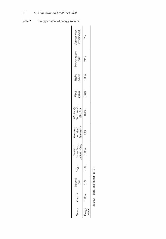
The amount of exergy content of energy sources was obtained directly or calculated from the information shown in Table 2.
The subsystems were selected based on the idea presented in the paper by Favrat et al. (2008), while the power plant was excluded from the system. Hence, the whole system was divided to three subsystems plus the energy source that shows the amount of energy and exergy enter into the system:
Exergy analysis of district energy systems and comparison 109
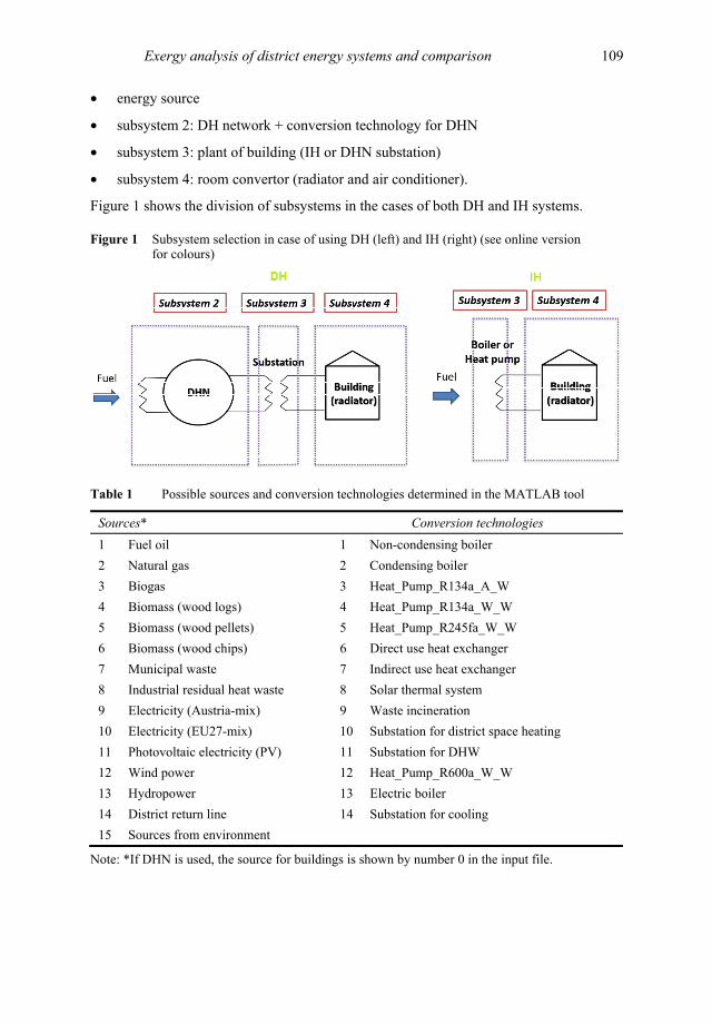
• energy source
• subsystem 2: DH network + conversion technology for DHN
• subsystem 3: plant of building (IH or DHN substation)
• subsystem 4: room convertor (radiator and air conditioner).
Figure 1 shows the division of subsystems in the cases of both DH and IH systems.
Figure 1 Subsystem selection in case of using DH (left) and IH (right) (see online version for colours)
Table 1 Possible sources and conversion technologies determined in the MATLAB tool
Sources* Conversion technologies 1 Fuel oil 1 Non-condensing boiler 2 Natural gas 2 Condensing boiler 3 Biogas 3 Heat_Pump_R134a_A_W 4 Biomass (wood logs) 4 Heat_Pump_R134a_W_W 5 Biomass (wood pellets) 5 Heat_Pump_R245fa_W_W 6 Biomass (wood chips) 6 Direct use heat exchanger 7 Municipal waste 7 Indirect use heat exchanger 8 Industrial residual heat waste 8 Solar thermal system 9 Electricity (Austria-mix) 9 Waste incineration 10 Electricity (EU27-mix) 10 Substation for district space heating 11 Photovoltaic electricity (PV) 11 Substation for DHW 12 Wind power 12 Heat_Pump_R600a_W_W 13 Hydropower 13 Electric boiler 14 District return line 14 Substation for cooling 15 Sources from environment
Note: *If DHN is used, the source for buildings is shown by number 0 in the input file.
110 E. Ahmadian and R-R. Schmidt
Table 2 Exergy content of energy sources
Sour
ce
Fuel
oil
Natu
ral
gas
Biog
as
Biom
ass
(woo
d lo
gs,
pelle
ts, c
hips
)
Indu
stri
al
resi
dual
he
at w
aste
Elec
tric
ity
(Aus
tria
-mix
, EU
, PV)
Win
d po
wer
H
ydro
po
wer
D
istr
ict r
etur
n lin
e So
urce
s fro
m
envi
ronm
ent
Exer
gy
cont
ent
100%
91
%
91%
10
0%
27%
10
0%
100%
10
0%
21%
0%
Sour
ce:
Bore
l and
Fav
rat (
2010
)
Exergy analysis of district energy systems and comparison 111
Technical data of each case study was collected in an Excel file as input to the MATLAB tool. Data was obtained with the help of the stakeholders in each case study. It included information about conversion technologies, load percentages, energy sources, exergy content of sources, primary energy factors, share of renewables, CO2 emission, building data, supply/return temperature of DHN and the buildings. To finalise the input data, the scenarios were defined by choosing different combinations of these parameters. Some scenarios had already been defined according to existing conversion technologies/sources in the local area, while other scenarios were theoretically defined based on information obtained from the literature review to understand the effect of important parameters (i.e., supply/return temperature of DHN and reference temperature) on the performance of these thermodynamic systems. Terehovics et al. (2017) used ‘exergy factor’ to investigate the effect of those two parameters on the exergy performance of a DHN in Latvia. From the results of the literature review, ‘exergy efficiency’ was considered as the selected indicator for exergy analysis of the case studies.
Exergy can be transferred across the boundaries of the system. Passing through each subsystem in Figure 1, there is exergy loss (Exloss) and destruction (Exdest) that decrease the exergy efficiency of the system (Bejan et al., 1996). The input exergy into the system is equal to the amount of exergy contains in the energy source (fuel). The accumulation of exergy loss and destruction in a system resulted from the difference between input (Exin) and output (Exout) exergy of the system [equation (1)].
dest loss in outEx Ex Ex Ex+ = − (1)
Hence, the exergy efficiency of system (η) is calculated through equation (2).
1out dest loss
in in
Ex Ex ExηEx Ex
+= = − (2)
Equations (1) and (2) can be applied to each subsystem separately in order to obtain exergy loss/destruction in each stage of the process. Since the subsystems are situated in series one after the other and input of each subsystem is the output of the previous one, the exergy efficiency of the whole system is obtained by simple multiplication through equation (3).
1 2 3systemη η η η= (3)
Applied equation for exergy assessment in the tool is equation (4), which calculates exergy flow of each subsystem by taking the energy flow values and multiplying them to Carnot factor.
1 ambientflow flow
flow
TEx EnT
= −
(4)
It calculates exergy flow in all subsystems, and consequently the exergy efficiency of each subsystem is calculated using equation (2).
Energy losses in DHN are calculated through equation (5) considering supply/return network temperatures, the average outdoor temperature, as well as the total length of piping (Lsupply).
112 E. Ahmadian and R-R. Schmidt
22
sup retloss supply out
T TQ L UA T
+ = −
(5)
U is heat transfer coefficient and A is heat transfer surface.
2.1.1 Graz DHN This case study, using the return line of the existing DHN from the city of Graz, prepared the DHW and SH of five buildings where DHW supply/return temperatures were 65/40°C for four of the buildings and 65/35°C for one building, and SH supply/return temperatures were 53/32.5°C for four buildings and 56.3/36.5°C for the fifth building. The length of the pipelines was 350 m. Four scenarios were defined for this case study where the reference temperature (environmental temperature) was considered to be 5°C for all cases.
• Scenario 1 is a DHN with supply/return temperature of 120/60°C using natural gas by non-condensing boiler.
• Scenario 2 is IH using electricity (Austria-mix) by heat pump (R134a_W_W).
• Scenario 3 is IH using natural gas by condensing boiler.
• Scenario 4 is a DHN with supply/return temperature of 60/40°C using district return line by indirect use heat exchanger.
In the IH scenarios the pipe length of the DHN was considered zero and the supply/return temperature of DHN was excluded from the calculation.
2.1.2 Güssing DHN Situated in the city of Güssing, it prepared DHW and SH for 237 buildings with DHW supply/return temperatures of 45/35°C for all buildings; while SH supply/return temperatures were 35/25°C for 233 buildings, 40/25°C for three buildings and 45/25°C for one building. The length of the pipeline of the DHN was 11,495 m. Three scenarios were defined for this case study where the reference temperature was considered 5°C for all cases.
• Scenario 1 is a DHN with supply/return temperature of 90/60°C using biomass (wood chips) by non-condensing boiler.
• Scenario 2 is IH using electricity (Austria-mix) by heat pump (R134a_W_W).
• Scenario 3 is a DHN with supply/return temperature of 49/29°C using industrial residual heat waste by indirect use heat exchanger.
The idea of the last scenario was adapted from Torio and Schmidt, (2010) that illustrated the exergy efficiency improvement in low temperature DH using waste-heat as energy source.
Exergy analysis of district energy systems and comparison 113
2.1.3 Wörgl DHN Situated in the city of Wörgl, a section of the DHN prepared SH2 for six buildings, where the SH supply/return temperatures were 42/22°C for three buildings, 40/20°C for two buildings and 55/35°C for one building. The length of pipelines was 813 m. Four scenarios were defined for this case study where the reference temperature was considered 5°C for all cases. In one scenario, IH was considered to be compared to the cases where DH was utilised.
• Scenario 1 is IH using fuel oil for one building and natural gas for others by non-condensing boiler.
• Scenario 2 is a DHN with supply/return temperature of 85/55°C using 80% industrial residual waste heat by indirect use heat exchanger, 10% electricity (Austria-mix) by heat pump (R134a_W_W) and 10% biomass (wood chips) by non-condensing boiler.
• Scenario 3 is a DHN with supply/return temperature of 50/30°C using district return line by indirect use heat exchanger.
• Scenario 4 is a DHN with supply/return temperature of 50/30°C using electricity (Austria-mix) by heat pump (R134a_W_W).
As operating load impacts the exergy efficiency of system (Tontu et al., 2018), average load for conversion technologies was 80% in all case studies in order to make a decent comparison between different scenarios.
3 Results and discussion
The results of energy, exergy and environmental assessment contains both graphical and numerical expression of indicators. It includes the values of energy/exergy flows of each subsystem as well as energy/exergy efficiencies and CO2 emissions of the whole system.
3.1 Exergy and energy performance of the system and their possible relationship
Figures 2–4 show the compact form of the results of the Graz, Güssing and Wörgl case studies containing energy/exergy flows (on yearly basis) for each subsystem plus the energy/exergy efficiencies of the whole system. The vertical axis shows the energy and exergy existing in the system. Proceeding from the abscissa and passing through any of the subsystems a thermodynamic process occurs that causes energy loss and exergy destruction, resulting in a decrease in energy/exergy content of the whole system. The first column shows the amount of energy and exergy of the source where, depending on the form of the energy, the exergy content is different. Subsystem 2 (i.e., DHN) was missed in any graph related to IH scenario.
114 E. Ahmadian and R-R. Schmidt
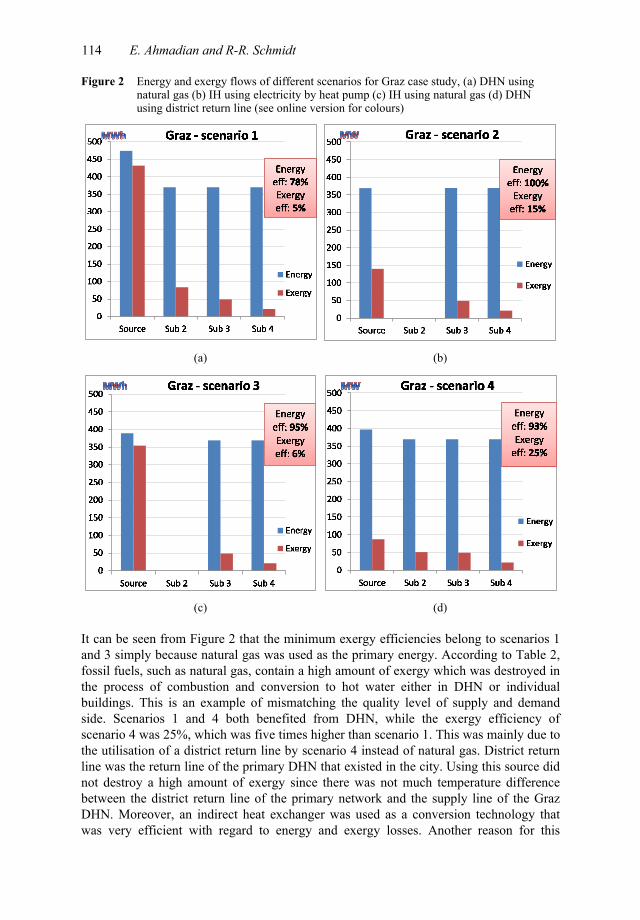
Figure 2 Energy and exergy flows of different scenarios for Graz case study, (a) DHN using natural gas (b) IH using electricity by heat pump (c) IH using natural gas (d) DHN using district return line (see online version for colours)
(a) (b)
(c) (d)
It can be seen from Figure 2 that the minimum exergy efficiencies belong to scenarios 1 and 3 simply because natural gas was used as the primary energy. According to Table 2, fossil fuels, such as natural gas, contain a high amount of exergy which was destroyed in the process of combustion and conversion to hot water either in DHN or individual buildings. This is an example of mismatching the quality level of supply and demand side. Scenarios 1 and 4 both benefited from DHN, while the exergy efficiency of scenario 4 was 25%, which was five times higher than scenario 1. This was mainly due to the utilisation of a district return line by scenario 4 instead of natural gas. District return line was the return line of the primary DHN that existed in the city. Using this source did not destroy a high amount of exergy since there was not much temperature difference between the district return line of the primary network and the supply line of the Graz DHN. Moreover, an indirect heat exchanger was used as a conversion technology that was very efficient with regard to energy and exergy losses. Another reason for this
Exergy analysis of district energy systems and comparison 115
exergy efficiency difference was the supply/return temperature of DHN which was lower in the case of scenario 4 leading to better exergy efficiency since less exergy was destroyed in the transmission of heat from the DHN to building in substations. Comparing scenarios 2 and 3 which were both individually heated buildings shows that utilising a heat pump instead of a boiler can considerably improve exergy efficiency of the system. It was due to obtaining heat from the environment by means of a heat pump and, since inputting heat from the environment has zero exergy (dead state condition), no high amount of exergy enters the system to be destroyed, although electricity entering the heat pump had 100% exergy. Hence, the combination of electricity and heat from the environment can improve exergy performance of a system compared to using only electricity or natural gas both of which contain almost 100% exergy.
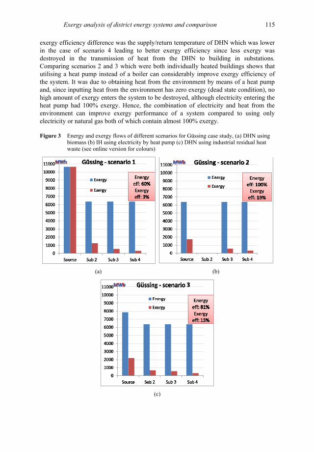
Figure 3 Energy and exergy flows of different scenarios for Güssing case study, (a) DHN using biomass (b) IH using electricity by heat pump (c) DHN using industrial residual heat waste (see online version for colours)
(a) (b)
(c)
116 E. Ahmadian and R-R. Schmidt
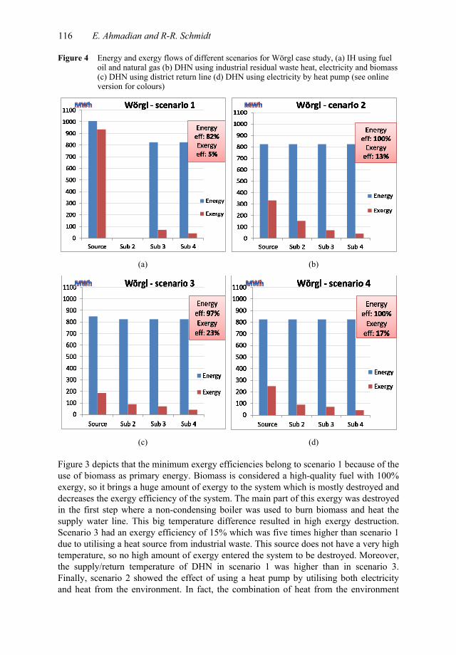
Figure 4 Energy and exergy flows of different scenarios for Wörgl case study, (a) IH using fuel oil and natural gas (b) DHN using industrial residual waste heat, electricity and biomass (c) DHN using district return line (d) DHN using electricity by heat pump (see online version for colours)
(a) (b)
(c) (d)
Figure 3 depicts that the minimum exergy efficiencies belong to scenario 1 because of the use of biomass as primary energy. Biomass is considered a high-quality fuel with 100% exergy, so it brings a huge amount of exergy to the system which is mostly destroyed and decreases the exergy efficiency of the system. The main part of this exergy was destroyed in the first step where a non-condensing boiler was used to burn biomass and heat the supply water line. This big temperature difference resulted in high exergy destruction. Scenario 3 had an exergy efficiency of 15% which was five times higher than scenario 1 due to utilising a heat source from industrial waste. This source does not have a very high temperature, so no high amount of exergy entered the system to be destroyed. Moreover, the supply/return temperature of DHN in scenario 1 was higher than in scenario 3. Finally, scenario 2 showed the effect of using a heat pump by utilising both electricity and heat from the environment. In fact, the combination of heat from the environment
Exergy analysis of district energy systems and comparison 117
(with zero exergy) and electricity (with 100% exergy) improved the exergy efficiency of system.
Figure 4 shows that the minimum exergy efficiency belongs to scenario 1 which was an IH. Again, there was high exergy destruction due to the use of fossil fuels. The other three scenarios had DHN in their process. Scenario 3 was the most exergy efficient scenario since it benefited from the district return line as a source, which contained small amount of exergy. Hence, less exergy was destroyed in this system compared to the others. Moreover, the low DHN supply/return temperature of scenario 3 was another advantage over scenario 2. Scenario 4, as mentioned, used electricity along with heat from the environment which improved the exergy efficiency. Scenario 2 benefited from three different sources. In addition to electricity (heat pump), it utilised heat from industrial waste (heat exchanger), which improved exergy efficiency, although using biomass (boiler) decreased the exergy efficiency. The higher DHN supply/return temperature of scenario 2 compared to scenario 4 could be one of the main reasons for obtaining lower exergy efficiency in scenario 2.
Regarding the energy efficiency, it was observed that the main energy losses occurred in the first step, which was ‘conversion technology plus DHN’ or ‘individual conversion technology’. In the case of DH, passing from the energy source to the output of DHN (subsystem 2), energy losses reduced the energy efficiency, while subsystem 3 (substation of DHN) was a heat exchanger with a very high energy efficiency (2 or 3% loss), hence, its efficiency was assumed to be 100% [Rosen and Dincer (2005) obtained energy efficiency of DHN very close to 100%]. In the case of IH (subsystem 2 excluded) passing from energy source to the output of subsystem 3, if it was a boiler, energy efficiency decreased, while if it was a heat pump, the energy loss was around 2% which was neglected in this tool. As can be seen in Figure 4, the energy efficiency of the system in scenarios 2 and 4 were 100%, which is not a realistic result because there surely are some losses in conversion technology and DHN. The reason is the presence of a heat pump in the system. In order to evaluate the total efficiency of a system, the effect of efficiency of each subsystem had to be considered. But the performance of a heat pump was evaluated using its coefficient of performance (COP), instead of efficiency, which is a value higher than one. Since the tool was programmed in such a way as to calculate the energy/exergy flows from demand side to supply side by adding the effect of the efficiency of each subsystem, when the effect of heat pump efficiency was applied, the COP of heat pump was taken into account (the value around 2 or 3). As a result, the value of the system’s total efficiency increased to an unrealistic value.
Energy efficiency in subsystem four (building) in all cases was shown at 100% because firstly, the energy efficiency of SH in the building was assumed to be 100% since the whole building was considered as control volume and any losses from the pipes was inside the control volume which was utilised for heating the building. Secondly, the amount of energy loss in the preparation of DHW depended on the method of preparation and connection of DHW system to the main system. DHW preparation system was composed of either a storage tank or simply uses direct preparation. In the former case, even the position of the storage tank in the system affected the efficiency. All mentioned factors can change energy losses of DHW system from 3% to 40%, and since there was no precise information about this part of the case studies and in addition, all DHW demands and losses were much less than SH demands and losses of buildings, the energy efficiency of building was assumed to be 100%.
118 E. Ahmadian and R-R. Schmidt
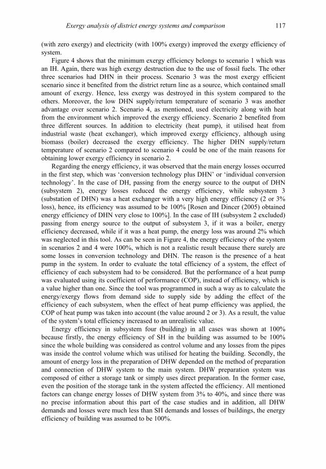
In order to understand the possible relationship between energy efficiency of a system and its exergy efficiency, the results of energy and exergy assessment of case studies was gathered into the scatter graph of Figure 5(a). No specific trend between energy efficiencies and exergy efficiencies of the case studies could be observed. Although there was a rising trend for the Güssing case study, it seems no rule was behind it and it occurred by chance. This could be a reasonable conclusion simply because exergy performance of a system strongly depends on reference temperature while it has a slight effect on the energetic performance of the system. Another factor that proves this unclear trend between energy and exergy efficiency is the type of energy source used for the system, because for a constant amount of energy demand, the amount of exergy entering the system is totally dependent on the type of energy source. Finally, some component in the system (e.g., heat exchanger) operates with very high energy efficiency (̴98%) while it has high exergy destruction (low exergy efficiency) due to temperature reduction.
Figure 5 (a) Relationship between exergy and energy efficiencies in NGH case studies (b) Trend of exergy efficiency with respect to quality of energy source based on case studies (see online version for colours)
(a) (b)
3.2 Relationship of exergy efficiency with exergy content of source
The main conclusion from the case studies proves the undeniable effect of the form of energy source (and its conversion technology) on the exergy efficiency of a system disregarding whether it was DH or IH. To clarify this effect, the analyses of exergy efficiencies versus the values of exergy content of energy sources of the case studies are gathered in a scatter graph (Table 2) used for each scenario and the results are shown in Figure 5(b). It is clear that the higher the exergy content of source, the lower the exergy efficiency of the system. Indeed, using high exergy content sources (like fossil fuels or biomass) caused huge exergy destruction in the first step. Consequently, the exergy efficiency of the whole system in the case of both individual and DH was around 3 to 6%. Utilising district return line considerably improved the exergy efficiency as the highest exergy efficiency belonged to Graz DHN with 25% efficiency, while utilising a heat pump improved exergy efficiency of both DH and IH systems up to around 15 to 19%.
Exergy analysis of district energy systems and comparison 119
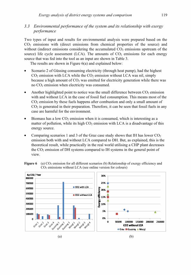
3.3 Environmental performance of the system and its relationship with exergy performance
Two types of input and results for environmental analysis were prepared based on the CO2 emissions with (direct emissions from chemical properties of the source) and without (indirect emissions considering the accumulated CO2 emissions upstream of the source) life cycle assessment (LCA). The amounts of CO2 emissions for each energy source that was fed into the tool as an input are shown in Table 3.
The results are shown in Figure 6(a) and explained below:
• Scenario 2 of Güssing consuming electricity (through heat pump), had the highest CO2 emission with LCA while the CO2 emission without LCA was nil, simply because a high amount of CO2 was emitted for electricity generation while there was no CO2 emission when electricity was consumed.
• Another highlighted point to notice was the small difference between CO2 emission with and without LCA in the case of fossil fuel consumption. This means most of the CO2 emission by these fuels happens after combustion and only a small amount of CO2 is generated in their preparation. Therefore, it can be seen that fossil fuels in any case are harmful for the environment.
• Biomass has a low CO2 emission when it is consumed, which is interesting as a matter of pollution, while its high CO2 emission with LCA is a disadvantage of this energy source.
• Comparing scenarios 1 and 3 of the Graz case study shows that IH has lower CO2 emission both with and without LCA compared to DH. But, as explained, this is the theoretical result, while practically in the real world utilising a CHP plant decreases the CO2 emission of DH systems compared to IH systems in the general point of view.
Figure 6 (a) CO2 emission for all different scenarios (b) Relationship of exergy efficiency and CO2 emissions without LCA (see online version for colours)
(a) (b)
120 E. Ahmadian and R-R. Schmidt
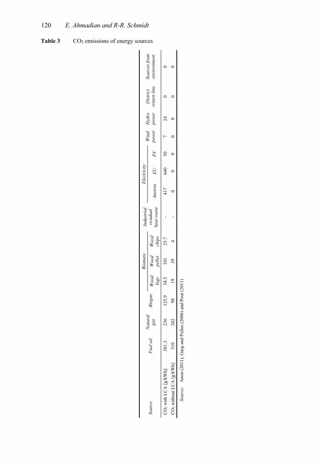
Table 3 CO2 emissions of energy sources
Sour
ce
Fuel
oil
Nat
ural
ga
s Bi
ogas
Bi
omas
s In
dustr
ial
resid
ual
heat
was
te
Elec
tric
ity
Win
d po
wer
H
ydro
po
wer
D
istr
ict
retu
rn li
ne
Sour
ces f
rom
en
viro
nmen
t W
ood
logs
W
ood
pelle
t W
ood
chip
s Au
stri
a EU
PV
CO2 w
ith L
CA [g
/kW
h]
381.
3 23
6 12
5.9
34.5
10
1 25
.7
- 41
7 64
0 50
7
24
0 0
CO2 w
ithou
t LCA
[g/k
Wh]
31
0 20
2 98
19
39
4
- 0
0 0
0 0
0 0
Sour
ce:
Ano
n (2
011)
, Gar
g an
d Pu
lles (
2006
) and
Pou
t (20
11)
Exergy analysis of district energy systems and comparison 121
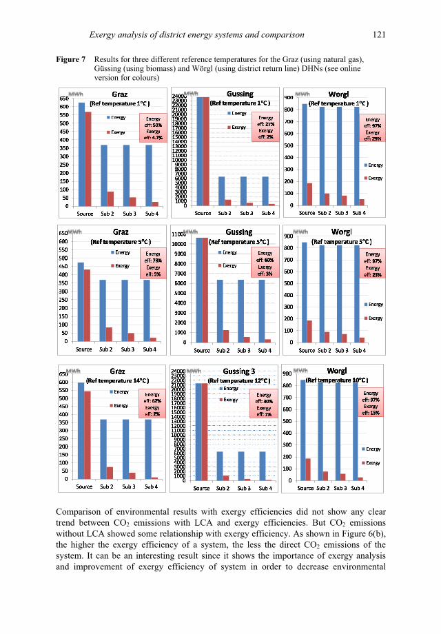
Figure 7 Results for three different reference temperatures for the Graz (using natural gas), Güssing (using biomass) and Wörgl (using district return line) DHNs (see online version for colours)
Comparison of environmental results with exergy efficiencies did not show any clear trend between CO2 emissions with LCA and exergy efficiencies. But CO2 emissions without LCA showed some relationship with exergy efficiency. As shown in Figure 6(b), the higher the exergy efficiency of a system, the less the direct CO2 emissions of the system. It can be an interesting result since it shows the importance of exergy analysis and improvement of exergy efficiency of system in order to decrease environmental
122 E. Ahmadian and R-R. Schmidt
pollution. All the points that stay on the vertical axis are the scenarios which used energy sources with zero CO2 emissions without LCA, such as district return line or heat pump. But the other four points, showing CO2 emissions, are the scenarios utilising energy sources such as fossil fuels or biomass.
3.4 Analysing the effect of influential parameters on the exergy efficiency of a system
In order to clarify the effects of supply/return temperature of DHN as well as reference temperature on the exergetic performance of a system and making a comparison between DH and IH, new scenarios were defined. These scenarios were theoretical and not practically applicable to the existing case studies.
3.4.1 Effect of reference temperature The presence of the environment temperature in equation (4) shows dependency of exergy analysis of the ambient temperature, which is usually considered as a reference temperature. To identify its effect on the exergy performance of a system, one scenario from each case study was selected. In order to specifically analyse the effect of the reference temperature, all parameters were kept constant and the only variable was the reference temperature. In the Graz case study, scenario 1 was selected and its reference temperature changed three times as 1°C, 5°C and 14°C. In the Güssing case study, scenario 1 was selected and its reference temperature changed three times as 1°C, 5°C and 12°C. In the Wörgl case study scenario 3 was selected and its reference temperature changed three times as 1°C, 5°C and 10°C. The results are shown in Figure 7 depicting that in the Graz and Güssing cases, both energy and exergy efficiencies increased to maximum at reference temperature of 5°C then decreased by increasing the reference temperature. Although apparently it can be concluded that to work at maximum efficiency the optimum reference temperature of 5°C should be chosen, the analysis in the Wörgl case study depicted the descending trend of exergy efficiency when the reference temperature increased, while the energy efficiency stayed constant in this case. As a result, no explicit trend of efficiency with respect to the reference temperature could be found.
3.4.2 Effect of supply/return temperature of DHN The concept of fourth generation district heating (4GDH) was developed by Lund et al. (2014). It is associated with low temperature DH that makes DHN compatible with use of renewable energy sources and reuse of industrial waste heat (Gong and Werner, 2015). To show the effect of the supply/return temperature of DHN on the results of analysis, new scenarios were defined by keeping all parameters constant except the supply/return temperature of the network. In Graz, two different supply/return temperatures of 140/80°C and 120/60°C were considered while all the other input data (e.g., conversion technology, energy source, reference temperature) were the same as scenario 1. In Wörgl, two different supply/return temperatures of 80/55°C and 50/30°C were considered while all the other input data were the same as scenario 3. The results of these four scenarios from two case studies were compacted in Figure 8. This illustrates that both energy and exergy efficiencies in the case studies improved by decreasing the supply/return
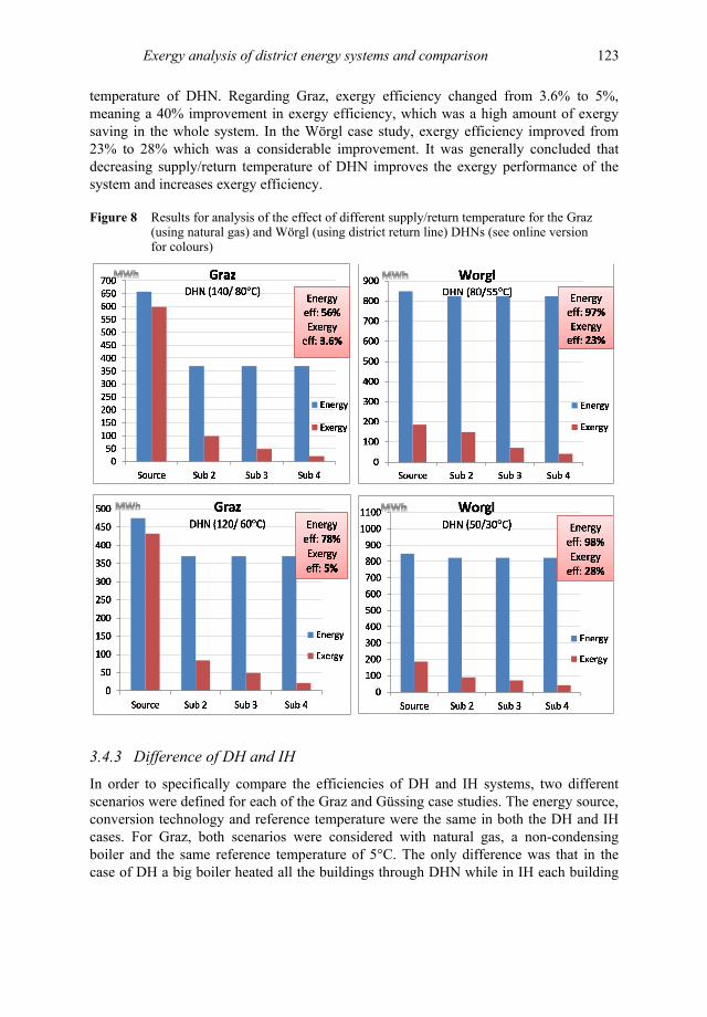
Exergy analysis of district energy systems and comparison 123
temperature of DHN. Regarding Graz, exergy efficiency changed from 3.6% to 5%, meaning a 40% improvement in exergy efficiency, which was a high amount of exergy saving in the whole system. In the Wörgl case study, exergy efficiency improved from 23% to 28% which was a considerable improvement. It was generally concluded that decreasing supply/return temperature of DHN improves the exergy performance of the system and increases exergy efficiency.
Figure 8 Results for analysis of the effect of different supply/return temperature for the Graz (using natural gas) and Wörgl (using district return line) DHNs (see online version for colours)
3.4.3 Difference of DH and IH In order to specifically compare the efficiencies of DH and IH systems, two different scenarios were defined for each of the Graz and Güssing case studies. The energy source, conversion technology and reference temperature were the same in both the DH and IH cases. For Graz, both scenarios were considered with natural gas, a non-condensing boiler and the same reference temperature of 5°C. The only difference was that in the case of DH a big boiler heated all the buildings through DHN while in IH each building
124 E. Ahmadian and R-R. Schmidt
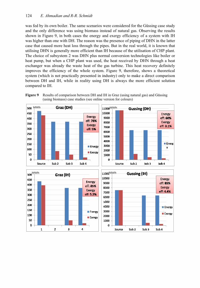
was fed by its own boiler. The same scenarios were considered for the Güssing case study and the only difference was using biomass instead of natural gas. Observing the results shown in Figure 9, in both cases the energy and exergy efficiency of a system with IH was higher than one with DH. The reason was the presence of piping of DHN in the latter case that caused more heat loss through the pipes. But in the real world, it is known that utilising DHN is generally more efficient than IH because of the utilisation of CHP plant. The choice of subsystem 2 was DHN plus normal conversion technologies like boiler or heat pump, but when a CHP plant was used, the heat received by DHN through a heat exchanger was already the waste heat of the gas turbine. This heat recovery definitely improves the efficiency of the whole system. Figure 9, therefore, shows a theoretical system (which is not practically presented in industry) only to make a direct comparison between DH and IH, while in reality using DH is always the more efficient solution compared to IH.
Figure 9 Results of comparison between DH and IH in Graz (using natural gas) and Güssing (using biomass) case studies (see online version for colours)
Exergy analysis of district energy systems and comparison 125
3.5 Comparison with other studies
The results obtained in this study are compared to the outcome of similar studies in the literature as following:
The highest exergy destruction occurs in conversion technology which could be a power plant, boiler, heat pump etc. Hence, the most effective factor on exergy performance of system was the type of energy source. This was approved according the data obtained from the literature (Rosen and Dincer, 2005; Rosen and Tang, 2008) even if it is a solar power plant (Saxena and Reddy, 2018). The higher the exergy content of source, the lower the exergy efficiency of the system. It was recommended by De Campos et al. (2019) to burn low-grade fuels in combustion process of power plant. The results from case study analysis demonstrated the exergy efficiency improvement due to employing a heat pump in the system, which was confirmed by the researches done by Dillon et al. (2019) and Sun et al. (2012). No specific correlation between exergy efficiency of the system and its reference temperature could be found. The overview of various studies in the literature illustrated the same fact (Keçebas, 2013; Li and Svendsen, 2012; Ünver and Kılıç, 2017). The results of case study analysis illustrated that lower temperature of DHN improve exergy performance of the system that is in line with the conclusion from other studies (Ertesvag, 2007; Torío et al., 2010; Verda and Kona, 2012). Moreover, according to Comakli et al. (2004), low supply temperature as well as high return temperature lead to a lower percentage of fuel exergy loss, which meant higher exergy efficiency is achieved by lowering the difference between supply and return temperature. According to Favrat et al. (2008) and Ossebaard et al. (1997), exergy efficiency of DH plant technology (DHN plus CHP plant) was higher than an individual boiler, while the results from the case study analysis showed that IH systems generally had slightly higher exergy efficiency than DH systems. That is because of the extra heat losses from DHN pipelines, though the main exergy destructions happen in the boiler (Tontu et al., 2018) that exists in both cases. In this specific case, the results shown in the literature were more acceptable since those systems benefited from a CHP plant while in this study, in the theoretical scenarios CHP plant was excluded from the system.
4 Conclusions
The conclusions from the analysis of three DHNs in Austria using simulation tool, in addition to the comprehensive literature overview, are summarised below:
• The most popular exergy indicator in the literature was exergy efficiency, although some other indicators were used by a few researchers.
• In general, the closer the exergy level of supply is to demand the less exergy destruction happens. Hence, in order to decrease exergy destruction of heating systems, low exergy level sources should be used due to low exergy level of demand side. As a consequence, the concept of low temperature heating was proposed since the lower the temperature of the source the less is its exergy content. In three case studies from the NGH project, the exergy efficiency of a system using high quality energy sources in case of both individual and DH was around 3% to 6%, while an
126 E. Ahmadian and R-R. Schmidt
example in the literature showed a system composed of cogeneration plant, DH and user heating had an exergy efficiency of 31%. This improvement in exergy efficiency of the latter case is due to utilisation of CHP plant which produces electricity and recovers the waste heat of the plant as the energy source for DHN.
• Utilising a heat pump improved exergy efficiency of both district and IH system. According to the analysis of the case studies, heat pump increased exergy efficiency of system up to around 15% to 19%, and the energy efficiency of the system up to 100% (neglecting 2 or 3% losses); moreover, using district return line considerably improved the exergy efficiency to its highest value.
• The effect of reference temperature on exergy efficiency was not clear since in some cases efficiency increased by increasing outdoor temperature while in other cases it decreased.
• Lowering supply and/or return temperatures increased the exergy efficiency of DHN and consequently the whole system. According to the literature, the lower the difference between supply and return temperature, the higher exergy efficiency.
• The results of the environmental analysis of the case studies depicted that the higher the exergy efficiency of a system, the less direct CO2 emissions there are, while there was no relationship between exergy efficiency and indirect CO2 emission. An important conclusion from exergetic and environmental assessment was that using energy sources such as fossil fuels is neither exergetically efficient nor advantageous against environmental pollution.
Acknowledgements
The authors would like to thank Professor Pietro Asinari and Vittorio Verda from Polytechnic University of Turin for their continues support and advices in the framework of this project.
References Anon (2011) Österreichisches Institut für Bautechnik, OIB-Richtlinie, p.6 [online] http://www.oib.
or.at/RL6_061011.pdf (accessed October 2014). Arslan, O. et al. (2009) Exergoeconomic evaluation on the optimum heating circuit system of
Simav geothermal district heating system’, Energy and Buildings, Vol. 41, No. 12, pp.1325–1333.
Bejan, A., Tsatsaronis, G. and Moran, M. (1996) Thermal Design and Optimization, Wiley, s.l. Borel, L. and Favrat, D. (2010) Thermodynamics and Energy Systems Analysis – from Energy to
Exergy, EPFL Press, s.l. Calli, O., Colpan, C.O. and Gunerhan, H. (2019) ‘Energy, exergy and thermoeconomic analyses of
biomass and solar powered organic Rankine cycles’, International Journal of Exergy, Vol. 29, No. 2–4, pp.172–192.
Comakli, K., Yuksel, B. and Comakli, O. (2004) ‘Evaluation of energy and exergy losses in district heating network’, Applied Thermal Engineering, Vol. 24, No. 7, pp.1009–1017.
Exergy analysis of district energy systems and comparison 127
De Campos, G.B., Bringhenti, C. and Tomita, J.T. (2019) ‘Exergy-based parallel between steam- and combined-cycle power plant configurations burning blast furnace gas’, International Journal of Exergy, Vol. 29, No. 1, pp.89–108.
Dillon, H.E., Dzombak, R. and Antonopoulos, C. (2019) ‘Exergy analysis of heating options for buildings in the Pacific Northwest’, International Journal of Exergy, Vol. 30, No. 3, pp.275–293.
Dincer, I. and Rosen, M. (2007) Exergy, Energy, Environment and Sustainable Development, Elsevier, s.l.
Dobrovicescu, A., Grosu, L. and Queiros-Condé, D. (2017) ‘Optimisation of a small solar organic Rankine cycle based on the exergetic analysis’, International Journal of Exergy, Vol. 22, No. 1, pp.1–28.
Energieforschung (2012) Forschung Für Unsere Zukunft [online] https://www.energieforschung.at/ projekte/259/niedertemperaturfernwaerme-am-beispiel-unterschiedlicher-regionen-oesterreichs-mit-niedriger-waermebedarfsdichte (accessed September 2014).
Ertesvag, I.S. (2007) ‘Exergetic comparison of efficiency indicators for combined heat and power (CHP)’, Energy, Vol. 32, No. 11, pp.2038–2050.
Favrat, D., Marechel, F. and Epelly, O. (2008) ‘The challenge of introducing an exergy indicator in a local law on exergy’, Energy, Vol. 33, No. 2, pp.130–136.
Gadalla, M., Ratlamwala, T. and Dincer, I. (2010) ‘Energy and exergy analyses of an integrated fuel cell and absorption cooling system’, International Journal of Exergy, Vol. 7, No. 6, pp.731–754.
Garg, A. and Pulles, T. (2006) IPCC Guidelines for National Greenhouse Gas Inventories, p.23 [online] http://www.ipcc.ch/meetings/session25/doc4a4b/vol2.pdf (accessed October 2014).
Gong, M. and Werner, S. (2015) ‘Exergy analysis of network temperature levels in Swedish and Danish district heating systems’, Renewable Energy, Vol. 84, pp.106–113.
Hepbasli, A. (2008) ‘A key review on exergetic analysis and assessment of renewable energy resources for a sustainable future’, Renewable and Sustainable Energy Reviews, Vol. 12, No. 3, pp.593–661.
Hevert, H. and Hevert, S. (1980) ‘Second law analysis: an alternative indicator of system efficiency’, Energy, Vol. 5, Nos. 8–9, pp.865–873.
IEA (2017a) Buildings, International Energy Agency [online] https://www.iea.org/buildings/ (accessed January 2018).
IEA (2017b) Tracking Progress: Buildings, International Energy Agency [online] https://www.iea. org/etp/tracking2017/buildings/ (accessed January 2018).
IEA (2019) Energy Efficiency: Buildings, Agency International Energy [online] https://www. iea.org/topics/energyefficiency/buildings/ (accessed July 2019).
Keçebas, A. (2013) ‘Effect of reference state on the exergoeconomic evaluation of geothermal district heating systems’, Renewable and Sustainable Energy Reviews, Vol. 25, pp.462–469.
Köfinger, M., Basciotti, D. and Schmidt, R.R. (2016) Reduction of Return Temperatures in Urban District Heating Systems by the Implementation of Energy-Cascades, s.n, Seoul.
Lee, K. (2001) ‘Classification of geothermal resources by exergy’, Geothermics, Vol. 30, No. 4, pp.431–442.
Li, H. and Svendsen, S. (2012) ‘Energy and exergy analysis of low temperature district heating network’, Energy, Vol. 45, No. 1, pp.237–246.
Lund, H. et al. (2014) ‘4th generation district heating (4GDH): integrating smart thermal grids into future sustainable energy systems’, Energy, Vol. 68, pp.1–11.
Oktay, Z. and Dincer, I. (2009) ‘Exergoeconomic analysis of the Gonen geothermal district heating system for buildings’, Energy and Buildings, Volume 41, Issue 2, Pages 154-163.
Oktay, Z., Coskun, C. and Dincer, I. (2008) ‘Energetic and exergetic performance investigation of the Bigadic geothermal district heating system in Turkey’, Energy and Buildings, Vol. 40, No. 5, pp.702–709.
128 E. Ahmadian and R-R. Schmidt
Ossebaard, M., Van Wijk, A. and Van Wees, M. (1997) ‘Heat supply in the Netherlands: a systems analysis of costs, exergy efficiency, CO2 and NOx emissions’, Energy, Vol. 22, No. 11, pp.1087–1098.
Ozgener, L. and Ozgener, O. (2009) ‘Monitoring of energy exergy efficiencies and exergoeconomic parameters of geothermal district heating systems (GDHSs)’, Applied Energy, Vol. 86, No. 9, pp.1704–1711.
Ozgener, L., Hepbasli, A. and Dincer, I. (2007) ‘A key review on performance improvement aspects of geothermal district heating systems and applications’, Renewable and Sustainable Energy Reviews, Vol. 11, No. 8, pp.1675–1697.
Pout, C. (2011) Proposed Carbon Emission Factors and Primary Energy Factors for SAP 2012, p.13, s.n., s.l.
Rosen, M. and Dincer, I. (2005) ‘Efficiency analysis of a cogeneration and district energy system’, Applied Thermal Engineering, Vol. 25, No. 1, pp.147–159.
Rosen, M.A. (2002) ‘Can exergy help us understand and address environmental concerns?’, Exergy, An International Journal, Vol. 2, No. 4, pp.214–217.
Rosen, M.A. and Tang, R. (2008) ‘Improving steam power plant efficiency through exergy analysis: effects of altering excess combustion air and stack-gas temperature’, International Journal of Exergy, Vol. 5, No. 1, pp.31–51.
Saxena, P. and Reddy, K. (2018) ‘Energy-exergy-economic (E3) analysis of stand-alone solar thermal cogeneration power plant’, International Journal of Exergy, Vol. 25, No. 3, pp.224–251.
Schmidt, D. (2014) EBC ANNEX 64 LowEx Communities: Optimised Performance of Community Energy Supply Systems with Exergy Principles, Fraunhofer-Institute for Building Physics, Kassel.
Sun, F., Fu, L., Zhang, S. and Sun, J. (2012) ‘New waste heat district heating system with combined heat and power based on absorption heat exchange cycle in China’, Applied Thermal Engineering, Vol. 37, pp.136–144.
Terehovics, E., Veidenbergs, I. and Blumberga, D. (2017) ‘Exergy analysis for district heating network’, Energy Procedia, Vol. 113, pp.189–193.
Tontu, M., Bilgili, M. and Sahin, B. (2018) ‘Performance analysis of an industrial steam power plant with varying loads’, International Journal of Exergy, Vol. 27, No. 2, pp.231–250.
Torio, H. and Schmidt, D. (2010) ‘Development of system concepts for improving the performance of a waste heat district heating network with exergy analysis’, Energy and Buildings, Vol. 42, No. 10, pp.1601–1609.
Torio, H. and Schmidt, D. (2011) Annex 49: Low Exergy Systems for High-Performance Buildings and Communities, Fraunhofer Verlag, Stuttgart.
Torío, H., Schmidt, D. and Lück, K. (2010) Exergy Analysis for Improving the Operation of a Waste Heat District Heating Network for Domestic Hot Water and Space Heating Applications, Fraunhofer, Antalya.
Ünver, Ü. and Kılıç, M. (2017) ‘Influence of environmental temperature on exergetic parameters of a combined cycle power plant’, International Journal of Exergy, Vol. 22, No. 1, pp.73–88.
Van Gool, W. (1997) Energy Policy: Fairly Tales and Factualities, s.n., Dordrecht. Verda, V. and Kona, A. (2012) ‘Thermoeconomics as a tool for the design and analysis of energy
savings initiatives in buildings connected to district heating network’, International Journal of Thermodynamics, Vol. 15, No. 4, pp.221–229.
Yabanova, I. and Keçebas, A. (2013) ‘Development of ANN model for geothermal district heating system and a novel PID-based control strategy’, Applied Thermal Engineering, Vol. 51, Nos. 1–2, pp.908–916.
Zhang, H., Lei, B., Yu, T. and Zhao, Z. (2018) ‘Exergy analysis of two kinds of solar-driven cogeneration systems in Lhasa, Tibet, China’, International Journal of Photoenergy, Vol. 2018.

Exergy analysis of district energy systems and comparison 129
Notes 1 System elements capable of converting certain types of energy carriers to usable form of
energy. 2 DHW of buildings is prepared by electric boilers, not considered in this study.