Embed Size (px)
Citation preview
at SciVerse ScienceDirect
Energy 62 (2013) 46e61
Contents lists available
Energy
journal homepage: www.elsevier .com/locate/energy
Exergetic analysis of the integrated first- and second-generationethanol production from sugarcane
Reynaldo Palacios-Bereche a,*, Klever Joao Mosqueira-Salazar b, Marcelo Modesto a,Adriano V. Ensinas a, Silvia A. Nebra a,c, Luis M. Serra d, Miguel-Angel Lozano d
aCentre of Engineering, Modelling and Social Sciences, Federal University of ABC (CECS/UFABC), Avenida dos Estados 5001, Santo André,SP 09210-580, BrazilbMechanical Engineering School, University of Campinas, Cidade Universitária “Zeferino Vaz”, P.O. Box 6122, 13083-970 Campinas, SP, Brazilc Interdisciplinary Centre of Energy Planning, University of Campinas (NIPE/UNICAMP), Cidade Universitária “Zeferino Vaz”, Rua Cora Coralina 330,P.O. Box 6166, Campinas, SP, BrazildDepartamento de Ingeniería Mecánica, Universidad de Zaragoza, C/ Maria de Luna 3, 50018 Zaragoza, Spain
a r t i c l e i n f o
Article history:Received 30 November 2012Received in revised form13 April 2013Accepted 10 May 2013Available online 15 June 2013
Keywords:ExergyExergetic costSugarcaneEthanolEnzymatic hydrolysis
* Corresponding author. Tel.: þ55 11 49968215.E-mail addresses: [email protected]
gmail.com (R. Palacios-Bereche), [email protected]@ufabc.edu.br (M. Modesto),(A.V. Ensinas), [email protected] (S.A. Nebra),[email protected] (M.-A. Lozano).
0360-5442/$ e see front matter � 2013 Elsevier Ltd.http://dx.doi.org/10.1016/j.energy.2013.05.010
a b s t r a c t
This study carried out an exergetic analysis of a proposed ethanol production scheme in which a newprocess e enzymatic hydrolysis of sugarcane bagasse e is integrated into the conventional process.Seven cases were evaluated, among them a conventional ethanol production plant without hydrolysis, aconventional plant combined with hydrolysis and hydrolysate concentration by evaporation, and aconventional plant combined with hydrolysis and hydrolysate concentration by the membrane system.Process simulations were performed to evaluate mass and energy balances, adopting the pre-treatmentof sugarcane bagasse by steam explosion, and including an integrated cogeneration system. It wasassumed that sugarcane trash and lignin cake, a hydrolysis residue, are available as supplementary fuel.The exergies of streams involved in the process were calculated, along with their exergetic cost. For theconventional process, in which ethanol and surplus electricity are the major products, a second-lawefficiency of 28% was found. In the integrated process, with biogas as an additional product, a higherperformance in resources management was achieved, with values in the range of 35e37%.
� 2013 Elsevier Ltd. All rights reserved.
1. Introduction
The sugarcane industry is one of the most important economicsectors in Brazil, a position reached in large measure due to a highefficiency and competitiveness in the first-generation ethanolproduction process [1]. Nevertheless, the efficiency index and en-ergy balance can still be improved if a second-generation process,such as enzymatic hydrolysis of sugarcane bagasse and trash, isintegrated into the conventional process. However, from an energypoint of view, the introduction of bagasse hydrolysis can be a realchallenge, because bagasse, the raw material in the new process, isa fuel in the current one.
There are several studies in the literature evaluating the incor-poration of bagasse hydrolysis into current distilleries. CGEE
u.br, reynaldopalaciosbe@com (K.J. Mosqueira-Salazar),[email protected]@unizar.es (L.M. Serra),
All rights reserved.
(Center for Strategic Studies and Management in Science) [2] pro-duced a prospective study evaluating the ethanol production in-crease by means of an enzymatic hydrolysis process in projectedscenarios for the years 2015 and 2025. Dias et al. [3] studied theincorporation of the organosolv hydrolysis process with dilutedacid into the current ethanol production process. Dias et al. [4] alsostudied the incorporation of the ethanol production by enzymatichydrolysis into the conventional process adopting different pre-treatments and producing biogas from pentose liquor. Walter andEnsinas [5] concluded a preliminary analysis of two technologicalroutes for biofuel production from cellulosic materials (based onhydrolysis, and on gasification combined with the FischereTropschconversion processes). Macrelli et al. [6] carried out a techno-economic evaluation of ethanol production by enzymatic hydroly-sis taking into account the production of biogas from pentose liquorand its use in boilers as fuel. Furlan et al. [7] carried out themodelling and simulation of the integrated first- and second-generation ethanol production process including the optimizationof bagasse use.
However, the efficiency of an integrated process should beevaluated in terms of its sustainability and use of energy resources.
Nomenclature
ai activityEc exergetic cost (kW)E exergy (kW)Di exergy destruction (kW)e specific exergy (kJ/kg)ePH physical specific exergy of a stream (kJ/kg)eCH chemical specific exergy of a stream (kJ/kg)F fuel exergy (kW)FPU filter paper unith enthalpy (kJ/kg)
IU International unitk unitary exergetic costLi exergy losses (kW)M molar massP product exergy (kW)s entropy (kJ/kg-K)T temperature (�C)yi molar fractionWTS Water Treatment Systemε exergetic efficiency~ε0i chemical standard exergy of a pure component (kJ/kg)
Table 1Components used in simulation.
Database components
Silicon dioxide Calcium hydroxideWater Calcium phosphateSucrose AmmoniaGlucose Sulphuric acidPotassium oxide GlycerolAconitic acid Acetic acidPotassium chloride Succinic acidCarbon dioxide Isoamyl alcoholCarbon monoxide EthanolNitrogen XyloseOxygen Sulfur dioxideHydrogen Sulfurous acidNitrogen oxide FurfuralPhosphoric acid HydroxymethilfurfuralCreated components
Cellulose YeastHemicellulose Cellulase enzymeLignin
R. Palacios-Bereche et al. / Energy 62 (2013) 46e61 47
In this context, according to Ojeda et al. [8], exergy analysis servesas a unified and effective tool to evaluate global process efficiency,since it is a thermodynamic analysis technique based on the SecondLaw of Thermodynamics, capable of locating thermodynamic lossesand identifying their causes and their impact on the natural envi-ronment. There are several studies in the literature applying exergyanalysis to the ethanol production process by enzymatic hydrolysis[8e11], but none of them includes the concept of exergetic costanalysis.
Thus, the aim of this study is to carry out an exergetic analysisand an exergetic cost analysis of the ethanol production process byenzymatic hydrolysis of sugarcane bagasse integrated into theconventional process. Previous studies have shown that glucosehydrolysate, produced in the hydrolysis process, has a very lowglucose content, the actual figure depending on the solids contentin the hydrolysis reactors. For this reason, three levels of solidscontent in the hydrolysis reactor were simulated e 5%, 8%, and 10%e in order to evaluate the impact on the process energy con-sumption. Furthermore, an alternative method based on mem-branes is proposed to concentrate the glucose liquor. Sincepressure-driven membrane processes such as RO (reverseosmosis) and NF (nanofiltration) have the capability of removingwater from aqueous solutions without phase change, membranesystems consume less energy than other separation techniques[12,13].
In exergetic analysis, techniques are developed with the aim ofidentifying and evaluating thermodynamic inefficiencies in termsof exergy destruction and loss. Calculation of the exergetic cost ofthe process streams and products completes the analysis [14]. Onthis basis, changes can be made to pieces of equipment and/orprocesses in order to improve efficiency.
The novelty of this work lies in the exergy and exergetic costanalysis performed by means of the Theory of Exergetic Costapplied to the overall process. Moreover, the unitary exergetic costdisaggregation provided by the Exergetic Cost Formation methodgives a complete view of the impacts of each subsystem on the finalproduct cost. This type of analysis allows an overall evaluationtaking into account the utilities (i.e. steam and electricity) and theprocess itself. It is a very useful methodology when several prod-ucts (electricity, ethanol, biogas) are obtained from a single rawmaterial (sugarcane). Furthermore, these analyses provide anevaluation, from the point of view of the Second Law of Thermo-dynamics, of the advantages and disadvantages of membranes as aseparation technique, and their impact on the exergetic costs ofethanol and electricity.
2. Ethanol production process simulation
Several cases were evaluated in this study based on simulationsdeveloped in Refs. [15,16]. The simulations were modelled in Aspen
Plus�, based on data collected from the literature, as well as actualdata for the conventional process, and experimental data for thesecond-generation process.
2.1. Modelling and simulation
The model selected for property calculations depended on theoperation. In the cogeneration system, for combustion gases thechosen method was the RKS-BM, which uses the RedlicheKwongeSoave equation of state with the Boston Mathias function; thismodel is suitable for combustion calculations. For steams in thecogeneration system, the Steam Tables method of the Aspen Plussoftware was used.
For the sucroseewater solution (sugarcane juice), the UNIQUAC(UNIversal QUAsiChemical) model was selected, with the binaryparameters of Starzak andMathlouthi [17]. This model was deemedthe most appropriate to represent the boiling point elevation.However, for enthalpy calculation, there were significant errors incomparison to equations from the literature based on experimentaldata (Kadlec et al.’s equation). For this reason, a subroutine waswritten in Fortran for the enthalpy calculation of juice according tothe equations from the literature [16]. Finally, for ethanol mixturesin the distillation and dehydration steps, the UNIQUAC-RK modelwas selected.
Table 1 shows the components adopted in this study. Some ofthese are not found in the Aspen Plus� database; theywere created,and their properties inserted into the software according to datafrom the literature [16,18]. The sugarcane composition adopted forthis study is shown in Table 2. Cellulose, hemicellulose and lignin
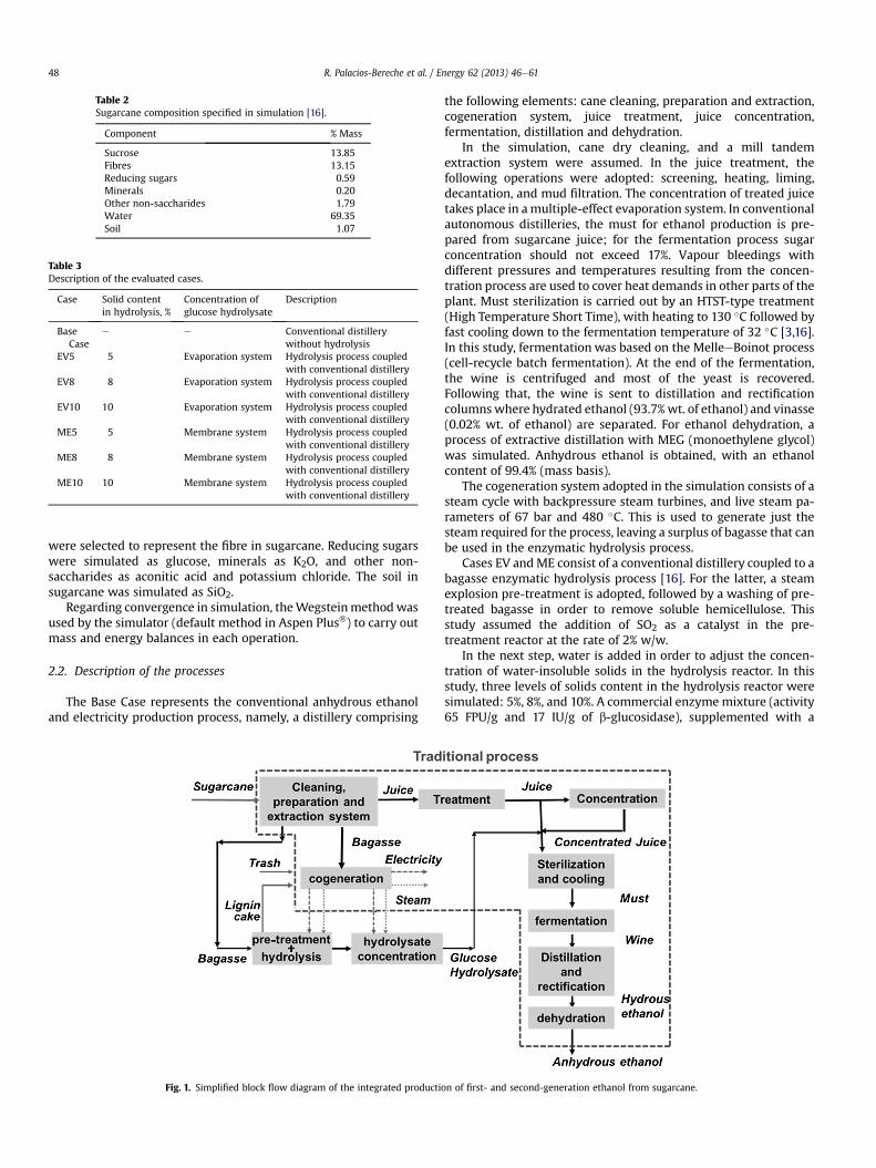
Table 2Sugarcane composition specified in simulation [16].
Component % Mass
Sucrose 13.85Fibres 13.15Reducing sugars 0.59Minerals 0.20Other non-saccharides 1.79Water 69.35Soil 1.07
Table 3Description of the evaluated cases.
Case Solid contentin hydrolysis, %
Concentration ofglucose hydrolysate
Description
BaseCase
e e Conventional distillerywithout hydrolysis
EV5 5 Evaporation system Hydrolysis process coupledwith conventional distillery
EV8 8 Evaporation system Hydrolysis process coupledwith conventional distillery
EV10 10 Evaporation system Hydrolysis process coupledwith conventional distillery
ME5 5 Membrane system Hydrolysis process coupledwith conventional distillery
ME8 8 Membrane system Hydrolysis process coupledwith conventional distillery
ME10 10 Membrane system Hydrolysis process coupledwith conventional distillery
R. Palacios-Bereche et al. / Energy 62 (2013) 46e6148
were selected to represent the fibre in sugarcane. Reducing sugarswere simulated as glucose, minerals as K2O, and other non-saccharides as aconitic acid and potassium chloride. The soil insugarcane was simulated as SiO2.
Regarding convergence in simulation, theWegsteinmethodwasused by the simulator (default method in Aspen Plus�) to carry outmass and energy balances in each operation.
2.2. Description of the processes
The Base Case represents the conventional anhydrous ethanoland electricity production process, namely, a distillery comprising
Fig. 1. Simplified block flow diagram of the integrated producti
the following elements: cane cleaning, preparation and extraction,cogeneration system, juice treatment, juice concentration,fermentation, distillation and dehydration.
In the simulation, cane dry cleaning, and a mill tandemextraction system were assumed. In the juice treatment, thefollowing operations were adopted: screening, heating, liming,decantation, and mud filtration. The concentration of treated juicetakes place in amultiple-effect evaporation system. In conventionalautonomous distilleries, the must for ethanol production is pre-pared from sugarcane juice; for the fermentation process sugarconcentration should not exceed 17%. Vapour bleedings withdifferent pressures and temperatures resulting from the concen-tration process are used to cover heat demands in other parts of theplant. Must sterilization is carried out by an HTST-type treatment(High Temperature Short Time), with heating to 130 �C followed byfast cooling down to the fermentation temperature of 32 �C [3,16].In this study, fermentation was based on the MelleeBoinot process(cell-recycle batch fermentation). At the end of the fermentation,the wine is centrifuged and most of the yeast is recovered.Following that, the wine is sent to distillation and rectificationcolumnswhere hydrated ethanol (93.7%wt. of ethanol) and vinasse(0.02% wt. of ethanol) are separated. For ethanol dehydration, aprocess of extractive distillation with MEG (monoethylene glycol)was simulated. Anhydrous ethanol is obtained, with an ethanolcontent of 99.4% (mass basis).
The cogeneration system adopted in the simulation consists of asteam cycle with backpressure steam turbines, and live steam pa-rameters of 67 bar and 480 �C. This is used to generate just thesteam required for the process, leaving a surplus of bagasse that canbe used in the enzymatic hydrolysis process.
Cases EV andME consist of a conventional distillery coupled to abagasse enzymatic hydrolysis process [16]. For the latter, a steamexplosion pre-treatment is adopted, followed by a washing of pre-treated bagasse in order to remove soluble hemicellulose. Thisstudy assumed the addition of SO2 as a catalyst in the pre-treatment reactor at the rate of 2% w/w.
In the next step, water is added in order to adjust the concen-tration of water-insoluble solids in the hydrolysis reactor. In thisstudy, three levels of solids content in the hydrolysis reactor weresimulated: 5%, 8%, and 10%. A commercial enzymemixture (activity65 FPU/g and 17 IU/g of b-glucosidase), supplemented with a
on of first- and second-generation ethanol from sugarcane.
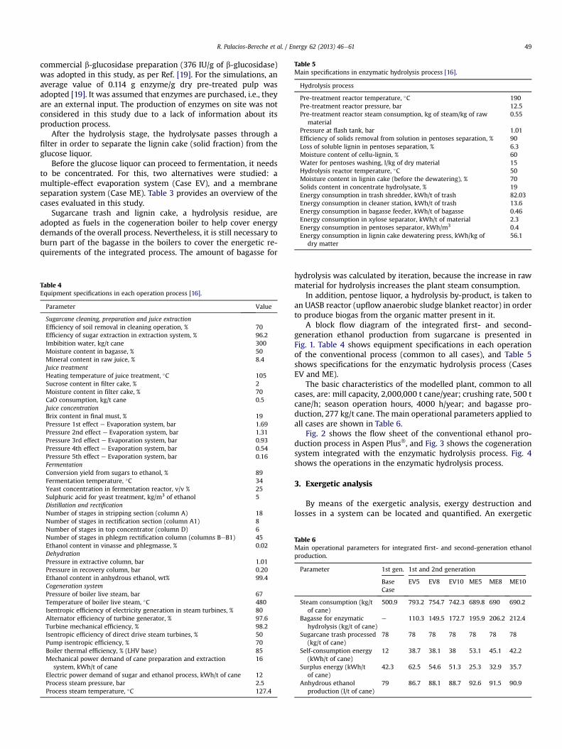
Table 5Main specifications in enzymatic hydrolysis process [16].
Hydrolysis process
Pre-treatment reactor temperature, �C 190Pre-treatment reactor pressure, bar 12.5Pre-treatment reactor steam consumption, kg of steam/kg of raw
material0.55
Pressure at flash tank, bar 1.01Efficiency of solids removal from solution in pentoses separation, % 90Loss of soluble lignin in pentoses separation, % 6.3Moisture content of cellu-lignin, % 60Water for pentoses washing, l/kg of dry material 15Hydrolysis reactor temperature, �C 50Moisture content in lignin cake (before the dewatering), % 70Solids content in concentrate hydrolysate, % 19Energy consumption in trash shredder, kWh/t of trash 82.03Energy consumption in cleaner station, kWh/t of trash 13.6Energy consumption in bagasse feeder, kWh/t of bagasse 0.46Energy consumption in xylose separator, kWh/t of material 2.3Energy consumption in pentoses separator, kWh/m3 0.4Energy consumption in lignin cake dewatering press, kWh/kg of
dry matter56.1
R. Palacios-Bereche et al. / Energy 62 (2013) 46e61 49
commercial b-glucosidase preparation (376 IU/g of b-glucosidase)was adopted in this study, as per Ref. [19]. For the simulations, anaverage value of 0.114 g enzyme/g dry pre-treated pulp wasadopted [19]. It was assumed that enzymes are purchased, i.e., theyare an external input. The production of enzymes on site was notconsidered in this study due to a lack of information about itsproduction process.
After the hydrolysis stage, the hydrolysate passes through afilter in order to separate the lignin cake (solid fraction) from theglucose liquor.
Before the glucose liquor can proceed to fermentation, it needsto be concentrated. For this, two alternatives were studied: amultiple-effect evaporation system (Case EV), and a membraneseparation system (Case ME). Table 3 provides an overview of thecases evaluated in this study.
Sugarcane trash and lignin cake, a hydrolysis residue, areadopted as fuels in the cogeneration boiler to help cover energydemands of the overall process. Nevertheless, it is still necessary toburn part of the bagasse in the boilers to cover the energetic re-quirements of the integrated process. The amount of bagasse for
Table 4Equipment specifications in each operation process [16].
Parameter Value
Sugarcane cleaning, preparation and juice extractionEfficiency of soil removal in cleaning operation, % 70Efficiency of sugar extraction in extraction system, % 96.2Imbibition water, kg/t cane 300Moisture content in bagasse, % 50Mineral content in raw juice, % 8.4Juice treatmentHeating temperature of juice treatment, �C 105Sucrose content in filter cake, % 2Moisture content in filter cake, % 70CaO consumption, kg/t cane 0.5Juice concentrationBrix content in final must, % 19Pressure 1st effect e Evaporation system, bar 1.69Pressure 2nd effect e Evaporation system, bar 1.31Pressure 3rd effect e Evaporation system, bar 0.93Pressure 4th effect e Evaporation system, bar 0.54Pressure 5th effect e Evaporation system, bar 0.16FermentationConversion yield from sugars to ethanol, % 89Fermentation temperature, �C 34Yeast concentration in fermentation reactor, v/v % 25Sulphuric acid for yeast treatment, kg/m3 of ethanol 5Distillation and rectificationNumber of stages in stripping section (column A) 18Number of stages in rectification section (column A1) 8Number of stages in top concentrator (column D) 6Number of stages in phlegm rectification column (columns BeB1) 45Ethanol content in vinasse and phlegmasse, % 0.02DehydrationPressure in extractive column, bar 1.01Pressure in recovery column, bar 0.20Ethanol content in anhydrous ethanol, wt% 99.4Cogeneration systemPressure of boiler live steam, bar 67Temperature of boiler live steam, �C 480Isentropic efficiency of electricity generation in steam turbines, % 80Alternator efficiency of turbine generator, % 97.6Turbine mechanical efficiency, % 98.2Isentropic efficiency of direct drive steam turbines, % 50Pump isentropic efficiency, % 70Boiler thermal efficiency, % (LHV base) 85Mechanical power demand of cane preparation and extraction
system, kWh/t of cane16
Electric power demand of sugar and ethanol process, kWh/t of cane 12Process steam pressure, bar 2.5Process steam temperature, �C 127.4
hydrolysis was calculated by iteration, because the increase in rawmaterial for hydrolysis increases the plant steam consumption.
In addition, pentose liquor, a hydrolysis by-product, is taken toan UASB reactor (upflow anaerobic sludge blanket reactor) in orderto produce biogas from the organic matter present in it.
A block flow diagram of the integrated first- and second-generation ethanol production from sugarcane is presented inFig. 1. Table 4 shows equipment specifications in each operationof the conventional process (common to all cases), and Table 5shows specifications for the enzymatic hydrolysis process (CasesEV and ME).
The basic characteristics of the modelled plant, common to allcases, are: mill capacity, 2,000,000 t cane/year; crushing rate, 500 tcane/h; season operation hours, 4000 h/year; and bagasse pro-duction, 277 kg/t cane. The main operational parameters applied toall cases are shown in Table 6.
Fig. 2 shows the flow sheet of the conventional ethanol pro-duction process in Aspen Plus�, and Fig. 3 shows the cogenerationsystem integrated with the enzymatic hydrolysis process. Fig. 4shows the operations in the enzymatic hydrolysis process.
3. Exergetic analysis
By means of the exergetic analysis, exergy destruction andlosses in a system can be located and quantified. An exergetic
Table 6Main operational parameters for integrated first- and second-generation ethanolproduction.
Parameter 1st gen. 1st and 2nd generation
BaseCase
EV5 EV8 EV10 ME5 ME8 ME10
Steam consumption (kg/tof cane)
500.9 793.2 754.7 742.3 689.8 690 690.2
Bagasse for enzymatichydrolysis (kg/t of cane)
e 110.3 149.5 172.7 195.9 206.2 212.4
Sugarcane trash processed(kg/t of cane)
78 78 78 78 78 78 78
Self-consumption energy(kWh/t of cane)
12 38.7 38.1 38 53.1 45.1 42.2
Surplus energy (kWh/tof cane)
42.3 62.5 54.6 51.3 25.3 32.9 35.7
Anhydrous ethanolproduction (l/t of cane)
79 86.7 88.1 88.7 92.6 91.5 90.9
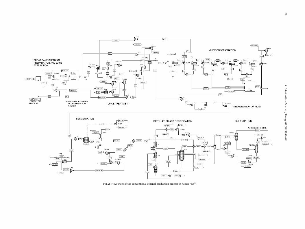
Fig. 2. Flow sheet of the conventional ethanol production process in Aspen Plus�.
R.Palacios-Berecheet
al./Energy
62(2013)
46e61
50
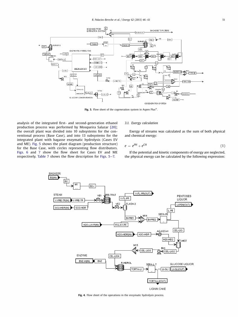
Fig. 3. Flow sheet of the cogeneration system in Aspen Plus�.
R. Palacios-Bereche et al. / Energy 62 (2013) 46e61 51
analysis of the integrated first- and second-generation ethanolproduction process was performed by Mosqueira Salazar [20];the overall plant was divided into 10 subsystems for the con-ventional process (Base Case), and into 13 subsystems for theintegrated plant with bagasse enzymatic hydrolysis (Cases EVand ME). Fig. 5 shows the plant diagram (production structure)for the Base Case, with circles representing flow distributors.Figs. 6 and 7 show the flow sheet for Cases EV and MErespectively. Table 7 shows the flow description for Figs. 5e7.
Fig. 4. Flow sheet of the operations in
3.1. Exergy calculation
Exergy of streams was calculated as the sum of both physicaland chemical exergy:
e ¼ ePH þ eCH (1)
If the potential and kinetic components of exergy are neglected,the physical exergy can be calculated by the following expression:
the enzymatic hydrolysis process.
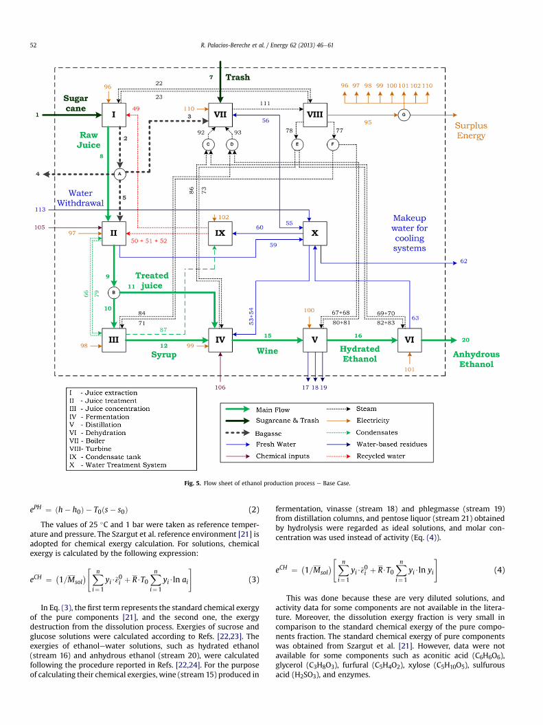
Fig. 5. Flow sheet of ethanol production process e Base Case.
R. Palacios-Bereche et al. / Energy 62 (2013) 46e6152
ePH ¼ ðh� h0Þ � T0ðs� s0Þ (2)
The values of 25 �C and 1 bar were taken as reference temper-ature and pressure. The Szargut et al. reference environment [21] isadopted for chemical exergy calculation. For solutions, chemicalexergy is calculated by the following expression:
eCH ¼ �1=Msol
�"Xni¼1
yi$~ε0i þ R$T0
Xni¼1
yi$ln ai
#(3)
In Eq. (3), the first term represents the standard chemical exergyof the pure components [21], and the second one, the exergydestruction from the dissolution process. Exergies of sucrose andglucose solutions were calculated according to Refs. [22,23]. Theexergies of ethanolewater solutions, such as hydrated ethanol(stream 16) and anhydrous ethanol (stream 20), were calculatedfollowing the procedure reported in Refs. [22,24]. For the purposeof calculating their chemical exergies, wine (stream 15) produced in
fermentation, vinasse (stream 18) and phlegmasse (stream 19)from distillation columns, and pentose liquor (stream 21) obtainedby hydrolysis were regarded as ideal solutions, and molar con-centration was used instead of activity (Eq. (4)).
eCH ¼ �1=Msol
�"Xni¼1
yi$~ε0i þ R$T0
Xni¼1
yi$ln yi
#(4)
This was done because these are very diluted solutions, andactivity data for some components are not available in the litera-ture. Moreover, the dissolution exergy fraction is very small incomparison to the standard chemical exergy of the pure compo-nents fraction. The standard chemical exergy of pure componentswas obtained from Szargut et al. [21]. However, data were notavailable for some components such as aconitic acid (C6H6O6),glycerol (C3H8O3), furfural (C5H4O2), xylose (C5H10O5), sulfurousacid (H2SO3), and enzymes.
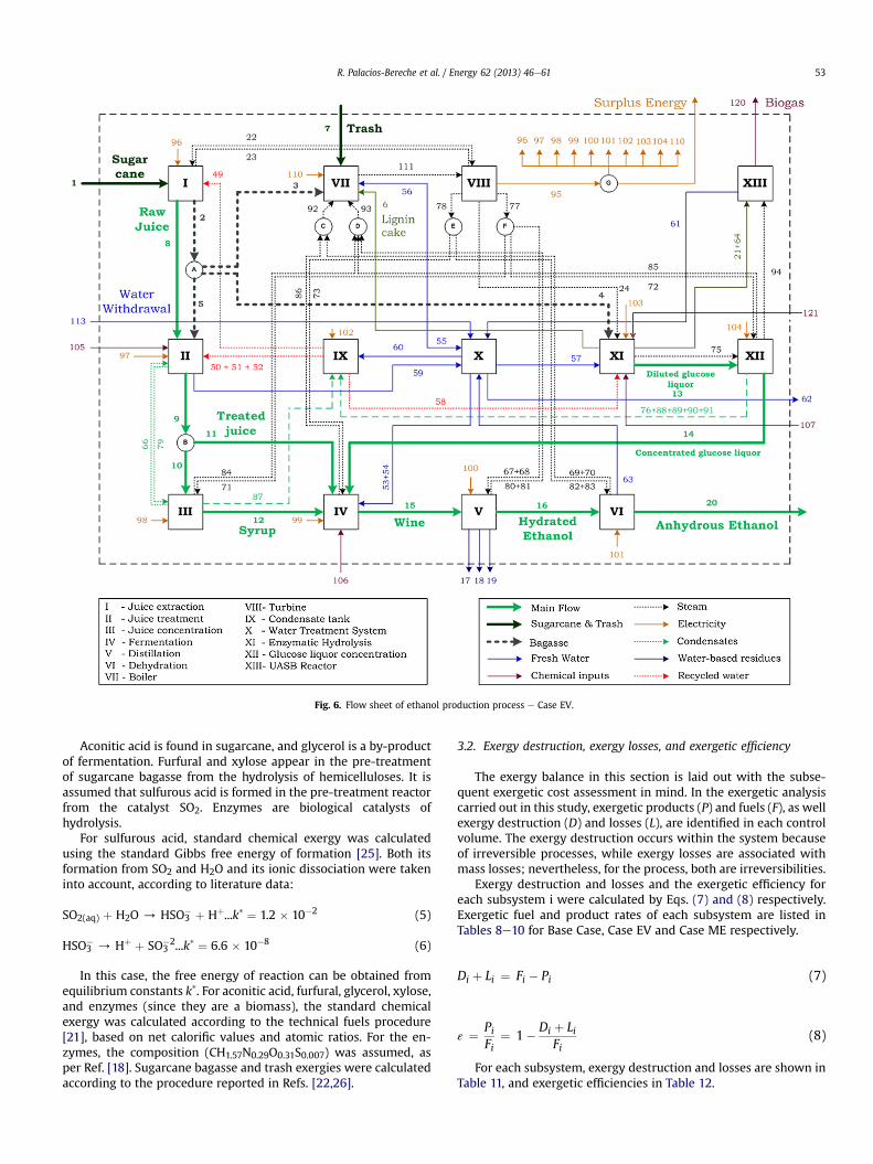
Fig. 6. Flow sheet of ethanol production process e Case EV.
R. Palacios-Bereche et al. / Energy 62 (2013) 46e61 53
Aconitic acid is found in sugarcane, and glycerol is a by-productof fermentation. Furfural and xylose appear in the pre-treatmentof sugarcane bagasse from the hydrolysis of hemicelluloses. It isassumed that sulfurous acid is formed in the pre-treatment reactorfrom the catalyst SO2. Enzymes are biological catalysts ofhydrolysis.
For sulfurous acid, standard chemical exergy was calculatedusing the standard Gibbs free energy of formation [25]. Both itsformation from SO2 and H2O and its ionic dissociation were takeninto account, according to literature data:
SO2(aq) þ H2O / HSO3� þ Hþ...k* ¼ 1.2 � 10�2 (5)
HSO3� / Hþ þ SO3
�2...k* ¼ 6.6 � 10�8 (6)
In this case, the free energy of reaction can be obtained fromequilibrium constants k*. For aconitic acid, furfural, glycerol, xylose,and enzymes (since they are a biomass), the standard chemicalexergy was calculated according to the technical fuels procedure[21], based on net calorific values and atomic ratios. For the en-zymes, the composition (CH1.57N0.29O0.31S0.007) was assumed, asper Ref. [18]. Sugarcane bagasse and trash exergies were calculatedaccording to the procedure reported in Refs. [22,26].
3.2. Exergy destruction, exergy losses, and exergetic efficiency
The exergy balance in this section is laid out with the subse-quent exergetic cost assessment in mind. In the exergetic analysiscarried out in this study, exergetic products (P) and fuels (F), as wellexergy destruction (D) and losses (L), are identified in each controlvolume. The exergy destruction occurs within the system becauseof irreversible processes, while exergy losses are associated withmass losses; nevertheless, for the process, both are irreversibilities.
Exergy destruction and losses and the exergetic efficiency foreach subsystem i were calculated by Eqs. (7) and (8) respectively.Exergetic fuel and product rates of each subsystem are listed inTables 8e10 for Base Case, Case EV and Case ME respectively.
Di þ Li ¼ Fi � Pi (7)
ε ¼ PiFi
¼ 1� Di þ LiFi
(8)
For each subsystem, exergy destruction and losses are shown inTable 11, and exergetic efficiencies in Table 12.
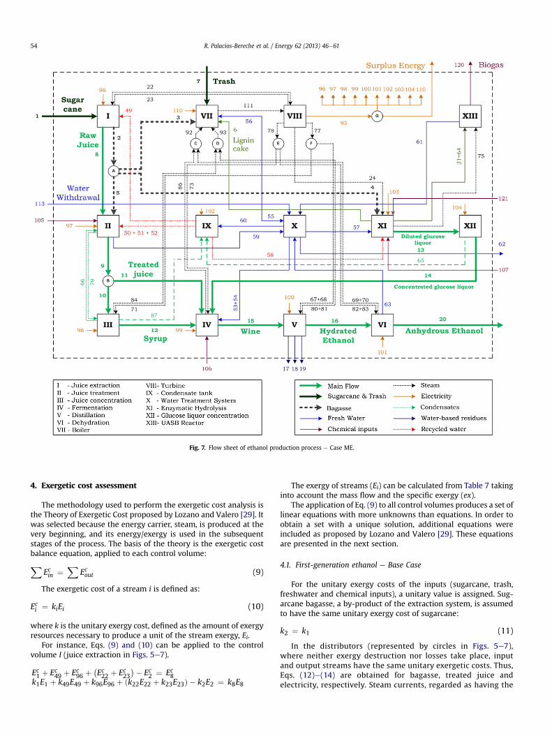
Fig. 7. Flow sheet of ethanol production process e Case ME.
R. Palacios-Bereche et al. / Energy 62 (2013) 46e6154
4. Exergetic cost assessment
The methodology used to perform the exergetic cost analysis isthe Theory of Exergetic Cost proposed by Lozano and Valero [29]. Itwas selected because the energy carrier, steam, is produced at thevery beginning, and its energy/exergy is used in the subsequentstages of the process. The basis of the theory is the exergetic costbalance equation, applied to each control volume:X
Ecin ¼X
Ecout (9)
The exergetic cost of a stream i is defined as:
Eci ¼ kiEi (10)
where k is the unitary exergy cost, defined as the amount of exergyresources necessary to produce a unit of the stream exergy, Ei.
For instance, Eqs. (9) and (10) can be applied to the controlvolume I (juice extraction in Figs. 5e7).
Ec1 þ Ec49 þ Ec96 þ�Ec22 þ Ec23
�� Ec2 ¼ Ec8k1E1 þ k49E49 þ k96E96 þ ðk22E22 þ k23E23Þ � k2E2 ¼ k8E8
The exergy of streams (Ei) can be calculated from Table 7 takinginto account the mass flow and the specific exergy (ex).
The application of Eq. (9) to all control volumes produces a set oflinear equations with more unknowns than equations. In order toobtain a set with a unique solution, additional equations wereincluded as proposed by Lozano and Valero [29]. These equationsare presented in the next section.
4.1. First-generation ethanol e Base Case
For the unitary exergy costs of the inputs (sugarcane, trash,freshwater and chemical inputs), a unitary value is assigned. Sug-arcane bagasse, a by-product of the extraction system, is assumedto have the same unitary exergy cost of sugarcane:
k2 ¼ k1 (11)
In the distributors (represented by circles in Figs. 5e7),where neither exergy destruction nor losses take place, inputand output streams have the same unitary exergetic costs. Thus,Eqs. (12)e(14) are obtained for bagasse, treated juice andelectricity, respectively. Steam currents, regarded as having the
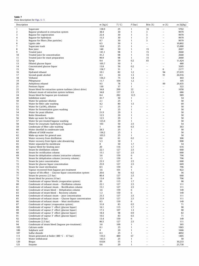
Table 7Flow description for Figs. 5e7.
Description m (kg/s) T (�C) P (bar) Brix (%) w (%) ex (kJ/kg)
1 Sugarcane 138.9 25 1 16 e 57622 Bagasse produced in extraction system 38.4 30 1 3 e 99793 Bagasse for cogeneration 22.4 30 1 3 e 99794 Bagasse for hydrolysis 15.3 30 1 3 e 99795 Bagasse for filters (fine particles) 0.7 30 1 3 e 99796 Lignin cake 6.5 50 1 e e 10,8027 Sugarcane trash 10.8 25 1 e e 15,8808 Raw juice 140 30 1 15 e 26979 Treated juice 141.1 98 1 15 e 266010 Treated juice for concentration 41.2 98 1 15 e 266011 Treated juice for must preparation 99.9 98 1 15 e 266012 Syrup 9.4 59 0.2 65 e 11,42413 Diluted glucose liquor 105.7 50 1 e e 48014 Concentrated glucose liquor 13.8 56 0.2 e e 326515 Wine 158.7 31 1 e 6 217716 Hydrated ethanol 10.1 82 1.2 e 94 27,63517 Second-grade alcohol 0.3 34 1.3 e 91 26,91618 Vinhasse 136.3 75 1.4 e e 44319 Phlegmasse 11.7 104 1.2 e e 10520 Anhydrous ethanol 9.5 78 1 e 99 29,43521 Pentoses liquor 130 37 1 e e 32222 Steam bleed for extraction system turbines (direct drive) 34.8 290 22 e e 105823 Exhaust steam of extraction system turbines 34.8 157 2.5 e e 68624 Steam bleed for bagasse pre-treatment 8.4 282 12.5 e e 98949 Imbibition water 41.7 50 1 e e 5450 Water for polymer dilution 2.1 25 1 e e 5051 Water for filter cake washing 4.2 80 1.5 e e 6952 Water for Ca(OH)2 dilution 1.1 25 1 e e 5053 Water for fermentation gases washing 4 25 1 e e 5054 Water for yeast dilution 21.9 29 1 e e 5055 Boiler blowdown 12.5 29 1 e e 5056 Make-up water for boiler 12.5 29 1 e e 5057 Water for pre-treated bagasse washing 123.4 29 1 e e 5058 Water for enzymatic hydrolysis of bagasse 103 50 2.5 e e 5459 Condensate of filter cake washing 1 69 0.3 e e 36360 Water shortfall in condensate tank 28.3 25 1 e e 5061 Effluent of UASB reactor 136.2 25 1 e e 5062 Make-up water for general uses 103.5 25 1 e e 5063 Water recovery from distillation 0.6 61 0.2 e e 30664 Water recovery from lignin cake dewatering 5.3 50 1 e e 90865 Water separated by membrane 0 50 1.7 e e 5466 Vapour bleed for heating juice 20 116 1.7 e e 61667 Steam for distillation column 22.1 127 2.5 e e 66868 Steam for rectification column 15.1 127 2.5 e e 66869 Steam for dehydration column (extractive column) 3.6 159 6 e e 79670 Steam for dehydration column (recovery column) 1.3 159 6 e e 79671 Steam for juice concentration 23.3 127 2.5 e e 66872 Steam for glucose liquor concentration 25.9 127 2.5 e e 66973 Steam for must sterilization 8.5 159 6 e e 79675 Vapour recovered from bagasse pre-treatment 3.6 101 1 e e 82276 Vapour of 5th effect e Glucose liquor concentration system 20.6 56 0.2 e e 5677 Steam for process (2.5 bar) 86.4 127 2.5 e e 66878 Steam bleed for process (6 bar) 13.4 159 6 e e 79679 Condensate of vapour bleeds (evaporation system) 20 115 1.7 e e 9880 Condensate of exhaust steam e Distillation column 22.1 127 2.5 e e 11181 Condensate of exhaust steam e Rectification column 15.1 127 2.5 e e 11182 Condensate of steam bleed e Dehydration column 3.6 159 6 e e 14983 Condensate of steam bleed e Recovery column 1.3 159 6 e e 14984 Condensate of exhaust steam e Juice concentration 23.3 127 2.5 e e 11185 Condensate of exhaust steam e Glucose liquor concentration 25.9 127 2.5 e e 11186 Condensate of exhaust steam e Must sterilization 8.5 159 6 e e 14987 Condensate of vapour (evaporation system) 31.8 83 0.5 e e 7188 Condensate of vapour 1� effect (glucose liquor) 16.1 115 1.7 e e 9889 Condensate of vapour 2� effect (glucose liquor) 17.3 107 1.3 e e 9090 Condensate of vapour 3� effect (glucose liquor) 18.4 98 0.9 e e 8291 Condensate of vapour 3� effect (glucose liquor) 19.5 83 0.5 e e 7192 Condensate (6 bar) 13.4 159 6 e e 14993 Condensate (2.5 bar) 86.5 127 2.5 e e 11194 Condensate of steam bleed (bagasse pre-treatment) 3.6 100 1 e e 365105 Calcium oxide 0.1 25 1 e e 1965106 Sulphuric acid 0 29 1 e e 1666107 Sulfur dioxide 0.3 25 1 e e 4892111 Steam generated at boiler (480 �C e 67 bar) 110.3 480 67 e e 1405113 Water withdrawal 143.3 25 1 e e 50120 Biogas 0.924 55 1 e e 30,233121 Enzyme 0.6 29 1 e e 23,730
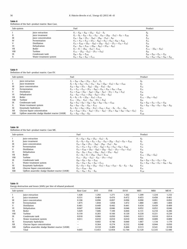
Table 8Definition of the fueleproduct matrix: Base Case.
Sub-system Fuel Product
I Juice extraction E1 þ E49 þ E96 þ (E22 � E23) � E2 E8II Juice treatment E5 þ E8 þ E50 þ E51 þ E52 � E59 þ (E66 � E79) þ E97 þ E105 E9III Juice concentration E10 þ E98 þ (E71 � E84) � (E66 � E79) � E87 E12IV Fermentation E11 þ E12 þ E14 þ (E73 � E86) þ E53 þ E54 þ E99 þ E106 E15V Distillation E15 þ E100 þ (E67 � E80) þ (E68 � E81) � (E17 þ E18 þ E19) E16VI Dehydration E16 � E63 þ E101 þ (E69 � E82) þ (E70 � E83) E20VII Boiler E3 þ E7 þ (E56 � E55) þ E110 E111 � (E92 þ E93)VIII Turbine E111 � (E22 � E23) � (E77 þ E78) E95IX Condensate tank E60 þ E87 þ E102 E49 þ E50 þ E51 þ E52X Water treatment system E55 þ E59 þ E63 þ E113 E53 þ E54 þ E56 þ E60 þ E62
Table 9Definition of the fueleproduct matrix: Case EV.
Sub-system Fuel Product
I Juice extraction E1 þ E49 þ E96 þ (E22 � E23) � E2 E8II Juice treatment E5 þ E8 þ E50 þ E51 þ E52 � E59 þ (E66 � E79) þ E97 þ E105 E9III Juice concentration E10 þ E98 þ (E71 � E84) � (E66 � E79) � E87 E12IV Fermentation E11 þ E12 þ E14 þ (E73 � E86) þ E53 þ E54 þ E99 þ E106 E15V Distillation E15 þ E100 þ (E67 � E80) þ (E68 � E81) � (E17 þ E18 þ E19) E16VI Dehydration E16 � E63 þ E101 þ (E69 � E82) þ (E70 � E83) E20VII Boiler E3 þ E6 þ E7 þ (E56 � E55) þ E110 E111 � (E92 þ E93)VIII Turbine E111 � (E22 � E23) � E24 � (E77 þ E78) E95IX Condensate tank E60 þ E76 þ E87 þ E88 þ E89 þ E90 þ E91 þ E102 E49 þ E50 þ E51 þ E52 þ E58X Water treatment system E55 þ E59 þ E61 þ E63 þ E113 E53 þ E54 þ E56 þ E57 þ E60 þ E62XI Enzymatic hydrolysis E4 þ E57 þ E58 þ (E24 � E75) þ E103 þ E107 � E6 � E21 � E64 E13XII Glucose liquor concentration E13 þ E104 þ (E75 � E94) þ (E72 � E85) � (E76 þ E88 þ E89 þ E90 þ E91) E14XIII Upflow anaerobic sludge blanket reactor (UASB) E21 þ E64 þ E94 � E61 E120
Table 10Definition of the fueleproduct matrix: Case ME.
Sub-system Fuel Product
I Juice extraction E1 þ E49 þ E96 þ (E22 � E23) � E2 E8II Juice treatment E5 þ E8 þ E50 þ E51 þ E52 � E59 þ (E66 � E79) þ E97 þ E105 E9III Juice concentration E10 þ E98 þ (E71 � E84) � (E66 � E79) � E87 E12IV Fermentation E11 þ E12 þ E14 þ (E73 � E86) þ E53 þ E54 þ E99 þ E106 E15V Distillation E15 þ E100 þ (E67 � E80) þ (E68 � E81) � (E17 þ E18 þ E19) E16VI Dehydration E16 � E63 þ E101 þ (E69 � E82) þ (E70 � E83) E20VII Boiler E3 þ E6 þ E7 þ (E56 � E55) þ E110 E111 � (E92 þ E93)VIII Turbine E111 � (E22 � E23) � E24 � (E77 þ E78) E95IX Condensate tank E60 þ E65 þ E87 þ E102 E49 þ E50 þ E51 þ E52 þ E58X Water treatment system E55 þ E59 þ E61 þ E63 þ E113 E53 þ E54 þ E56 þ E57 þ E60 þ E62XI Enzymatic hydrolysis E4 þ E57 þ E58 þ (E24 � E75) þ E103 þ E107 � E6 � E21 � E64 E13XII Glucose liquor concentration E13 þ E104 � E65 E14XIII Upflow anaerobic sludge blanket reactor (UASB) E21 þ E64 þ E75 � E61 E120
Table 11Exergy destruction and losses (kWh) per liter of ethanol produced.
Sub-system Base Case EV5 EV8 EV10 ME5 ME8 ME10
I Juice extraction 1.428 1.292 1.271 1.262 1.209 1.224 1.232II Juice treatment 0.531 0.484 0.476 0.472 0.453 0.458 0.461III Juice concentration 0.106 0.098 0.097 0.096 0.090 0.091 0.092IV Fermentation 1.875 1.844 1.858 1.872 1.880 1.885 1.884V Distillation 0.461 0.449 0.442 0.441 0.434 0.439 0.409VI Dehydration 0.047 0.046 0.046 0.046 0.052 0.052 0.046VII Boiler 5.029 7.606 7.109 6.844 6.131 6.218 6.286VIII Turbine 0.159 0.283 0.166 0.120 0.220 0.221 0.220IX Condensate tank 0.018 0.066 0.050 0.043 0.013 0.018 0.014X Water treatment system 0.011 0.010 0.010 0.010 0.009 0.009 0.009XI Enzymatic hydrolysis e 0.602 0.746 0.840 1.067 1.134 1.179XII Glucose liquor concentration e 0.364 0.274 0.232 0.048 0.044 0.050XIII Upflow anaerobic sludge blanket reactor (UASB) e 0.310 0.409 0.466 0.513 0.541 0.558
Total 9.665 13.453 12.954 12.744 12.120 12.335 12.440
R. Palacios-Bereche et al. / Energy 62 (2013) 46e6156
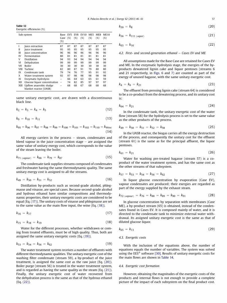
Table 12Exergetic efficiencies (%).
Sub-system BaseCase(%)
EV5(%)
EV8(%)
EV10(%)
ME5(%)
ME8(%)
ME10(%)
I Juice extraction 87 87 87 87 87 87 87II Juice treatment 95 95 95 95 95 95 95III Juice concentration 96 96 96 96 96 96 96IV Fermentation 80 81 81 81 81 81 81V Distillation 94 93 94 94 94 94 94VI Dehydration 99 99 99 99 99 99 99VII Boiler 30 30 30 30 30 30 30VIII Turbine 82 80 87 91 79 80 80IX Condensate tank 79 74 76 77 95 91 92X Water treatment system 92 97 98 98 98 98 98XI Enzymatic hydrolysis e 66 64 63 65 61 59XII Glucose liquor concentration e 74 82 85 97 97 97XIII Upflow anaerobic sludge
blanket reactor (UASB)e 68 68 67 68 68 68
R. Palacios-Bereche et al. / Energy 62 (2013) 46e61 57
same unitary exergetic cost, are drawn with a discontinuousblack line.
k2 ¼ k3 ¼ k4 ¼ k5 (12)
k9 ¼ k10 ¼ k11 (13)
k95 ¼ k96 ¼ k97 ¼ k98 ¼ k99 ¼ k100 ¼ k101 ¼ k102 ¼ k110 ¼ kWexc
(14)
All energy carriers in the process e steam, condensates andbleed vapour in the juice concentration stage e are assigned thesame value of unitary exergy cost, which corresponds to the valueof the steam leaving the boiler.
k71 ðvapourÞ ¼ k66 ¼ k79 ¼ k87 (15)
The condensate tank supplies streams composed of condensatesand freshwater having the same thermodynamic quality. The sameunitary exergy cost is assigned to all the streams.
k49 ¼ k50 ¼ k51 ¼ k52 (16)
Distillation by-products such as second-grade alcohol, phleg-masse and vinasse, are special cases. Because second-grade alcoholand hydrous ethanol have similar compositions and thermody-namic properties, their unitary exergetic costs are considered to beequal (Eq. (17)). The unitary costs of vinasse and phlegmasse are setto the same value as the main flow input, the wine (Eq. (18)).
k16 ¼ k17 (17)
k15 ¼ k18 ¼ k19 (18)
Water for the different processes, whether withdrawn or com-ing from treated effluents, must be of high quality. Thus, both areassigned the same unitary exergetic costs (Eq. (19)).
k53 ¼ k54 ¼ k56 ¼ k62 (19)
The water treatment system receives a number of effluents withdifferent thermodynamic qualities. The unitary exergetic cost of thewashing filter condensate (stream 59), a by-product of the juicetreatment, is assigned the same cost as the raw juice (Eq. (20)).Boiler purge (stream 56) is treated in the water treatment system,and is regarded as having the same quality as the steam (Eq. (21)).Finally, the unitary exergetic cost of water recovered fromthe dehydration process is the same as that of the hydrous ethanol(Eq. (22)).
k59 ¼ k8 (20)
k56 ¼ k111 ðvaporÞ (21)
k63 ¼ k16 (22)
4.2. First- and second-generation ethanol e Cases EV and ME
All assumptionsmade for the Base Case are retained for Cases EVand ME. In the enzymatic hydrolysis stage, the exergies of the by-products dewatered lignin cake and liquor pentoses (streams 6and 21 respectively, in Figs. 6 and 7) are counted as part of theexergy of unused bagasse, with the same unitary exergetic cost.
k4 ¼ k6 ¼ k21 (23)
The effluent from pressing lignin cake (stream 64) is consideredto be a co-product from the dewatering process, and its unitary costis:
k64 ¼ k21 (24)
In the condensate tank, the unitary exergetic cost of the waterflow (stream 58) for the hydrolysis process is set to the same valueas the other products of the process.
k49 ¼ k50 ¼ k51 ¼ k52 ¼ k58 (25)
In the UASB reactor, the biogas carries all the exergy destructionof the process, and consequently the unitary cost for the effluent(stream 61) is the same as for the principal affluent, the liquorpentoses.
k61 ¼ k21 (26)
Water for washing pre-treated bagasse (stream 57) is a co-product of the water treatment system, and has the same cost asthe other streams of that subsystem.
k57 ¼ k53 ¼ k54 ¼ k56 ¼ k62 (27)
In liquor glucose concentration by evaporation (Case EV),vapour condensates are produced; their exergies are regarded aspart of the exergy supplied by the exhaust steam.
k72 ðvapourÞ ¼ k76 ¼ k88 ¼ k89 ¼ k90 ¼ k91 (28)
In glucose concentration by separation with membranes (CaseME), a by-product stream (65) is obtained, instead of the conden-sates found in Cases EV. It is composed mainly of water, and it isdirected to the condensate tank to minimize external water with-drawal. Its assigned unitary exergetic cost is the same as that ofdiluted glucose liquor.
k65 ¼ k13 (29)
4.3. Exergetic costs
With the inclusion of the equations above, the number ofequations equals the number of variables. The system was solvedusing the EES� software [30]. Results of unitary exergetic costs forthe main flows are shown in Table 14.
4.4. Exergetic cost formation
However, obtaining the magnitudes of the exergetic costs of theproducts and internal flows is not enough to provide a completepicture of the impact of each subsystem on the final product cost.
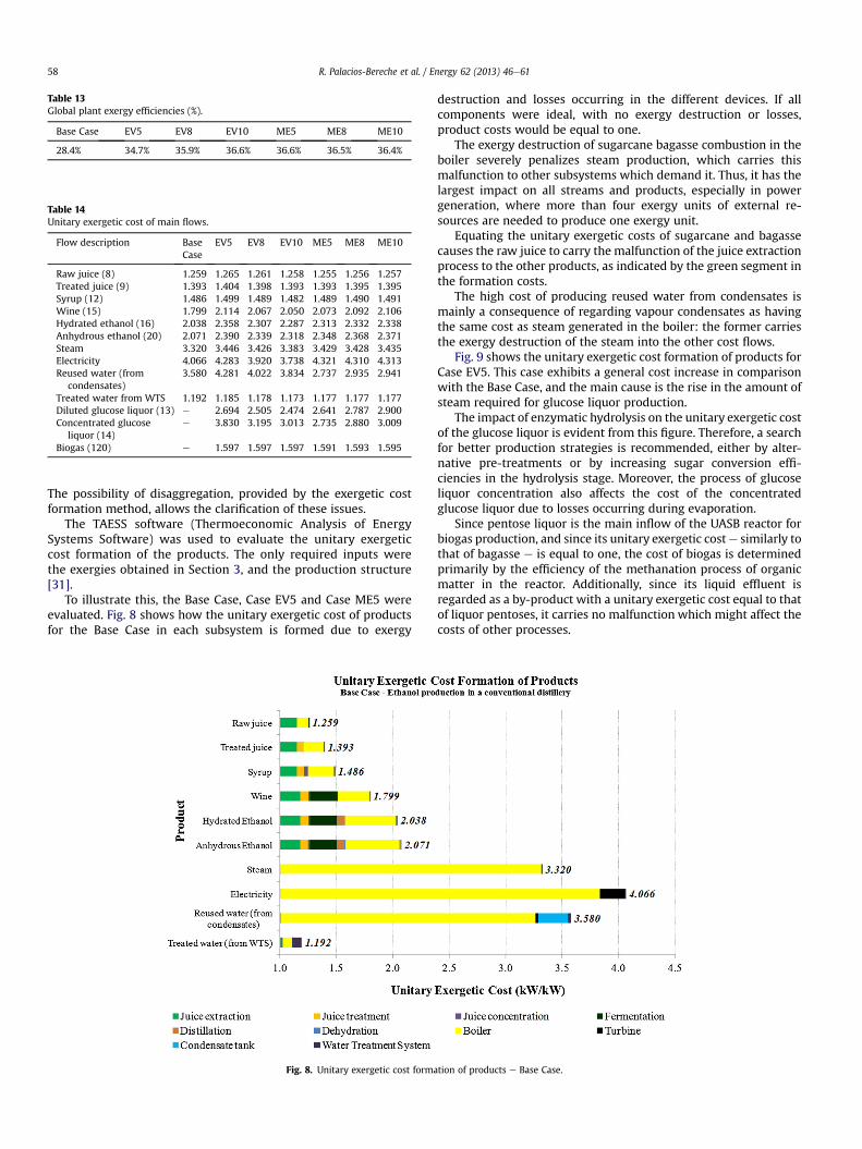
Table 13Global plant exergy efficiencies (%).
Base Case EV5 EV8 EV10 ME5 ME8 ME10
28.4% 34.7% 35.9% 36.6% 36.6% 36.5% 36.4%
Table 14Unitary exergetic cost of main flows.
Flow description BaseCase
EV5 EV8 EV10 ME5 ME8 ME10
Raw juice (8) 1.259 1.265 1.261 1.258 1.255 1.256 1.257Treated juice (9) 1.393 1.404 1.398 1.393 1.393 1.395 1.395Syrup (12) 1.486 1.499 1.489 1.482 1.489 1.490 1.491Wine (15) 1.799 2.114 2.067 2.050 2.073 2.092 2.106Hydrated ethanol (16) 2.038 2.358 2.307 2.287 2.313 2.332 2.338Anhydrous ethanol (20) 2.071 2.390 2.339 2.318 2.348 2.368 2.371Steam 3.320 3.446 3.426 3.383 3.429 3.428 3.435Electricity 4.066 4.283 3.920 3.738 4.321 4.310 4.313Reused water (from
condensates)3.580 4.281 4.022 3.834 2.737 2.935 2.941
Treated water from WTS 1.192 1.185 1.178 1.173 1.177 1.177 1.177Diluted glucose liquor (13) e 2.694 2.505 2.474 2.641 2.787 2.900Concentrated glucose
liquor (14)e 3.830 3.195 3.013 2.735 2.880 3.009
Biogas (120) e 1.597 1.597 1.597 1.591 1.593 1.595
R. Palacios-Bereche et al. / Energy 62 (2013) 46e6158
The possibility of disaggregation, provided by the exergetic costformation method, allows the clarification of these issues.
The TAESS software (Thermoeconomic Analysis of EnergySystems Software) was used to evaluate the unitary exergeticcost formation of the products. The only required inputs werethe exergies obtained in Section 3, and the production structure[31].
To illustrate this, the Base Case, Case EV5 and Case ME5 wereevaluated. Fig. 8 shows how the unitary exergetic cost of productsfor the Base Case in each subsystem is formed due to exergy
Fig. 8. Unitary exergetic cost forma
destruction and losses occurring in the different devices. If allcomponents were ideal, with no exergy destruction or losses,product costs would be equal to one.
The exergy destruction of sugarcane bagasse combustion in theboiler severely penalizes steam production, which carries thismalfunction to other subsystems which demand it. Thus, it has thelargest impact on all streams and products, especially in powergeneration, where more than four exergy units of external re-sources are needed to produce one exergy unit.
Equating the unitary exergetic costs of sugarcane and bagassecauses the raw juice to carry the malfunction of the juice extractionprocess to the other products, as indicated by the green segment inthe formation costs.
The high cost of producing reused water from condensates ismainly a consequence of regarding vapour condensates as havingthe same cost as steam generated in the boiler: the former carriesthe exergy destruction of the steam into the other cost flows.
Fig. 9 shows the unitary exergetic cost formation of products forCase EV5. This case exhibits a general cost increase in comparisonwith the Base Case, and the main cause is the rise in the amount ofsteam required for glucose liquor production.
The impact of enzymatic hydrolysis on the unitary exergetic costof the glucose liquor is evident from this figure. Therefore, a searchfor better production strategies is recommended, either by alter-native pre-treatments or by increasing sugar conversion effi-ciencies in the hydrolysis stage. Moreover, the process of glucoseliquor concentration also affects the cost of the concentratedglucose liquor due to losses occurring during evaporation.
Since pentose liquor is the main inflow of the UASB reactor forbiogas production, and since its unitary exergetic coste similarly tothat of bagasse e is equal to one, the cost of biogas is determinedprimarily by the efficiency of the methanation process of organicmatter in the reactor. Additionally, since its liquid effluent isregarded as a by-product with a unitary exergetic cost equal to thatof liquor pentoses, it carries no malfunction which might affect thecosts of other processes.
tion of products e Base Case.
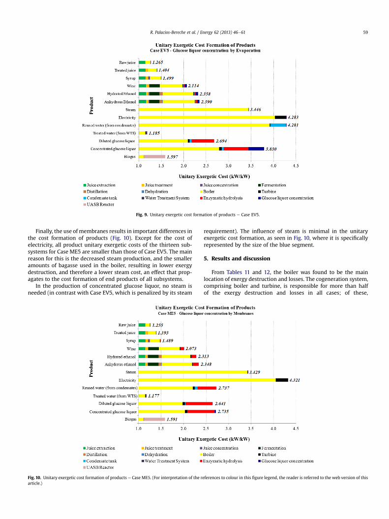
Fig. 9. Unitary exergetic cost formation of products e Case EV5.
R. Palacios-Bereche et al. / Energy 62 (2013) 46e61 59
Finally, the use of membranes results in important differences inthe cost formation of products (Fig. 10). Except for the cost ofelectricity, all product unitary exergetic costs of the thirteen sub-systems for Case ME5 are smaller than those of Case EV5. The mainreason for this is the decreased steam production, and the smalleramounts of bagasse used in the boiler, resulting in lower exergydestruction, and therefore a lower steam cost, an effect that prop-agates to the cost formation of end products of all subsystems.
In the production of concentrated glucose liquor, no steam isneeded (in contrast with Case EV5, which is penalized by its steam
Fig. 10. Unitary exergetic cost formation of products e Case ME5. (For interpretation of the rarticle.)
requirement). The influence of steam is minimal in the unitaryexergetic cost formation, as seen in Fig. 10, where it is specificallyrepresented by the size of the blue segment.
5. Results and discussion
From Tables 11 and 12, the boiler was found to be the mainlocation of exergy destruction and losses. The cogeneration system,comprising boiler and turbine, is responsible for more than halfof the exergy destruction and losses in all cases; of these,
eferences to colour in this figure legend, the reader is referred to the web version of this
R. Palacios-Bereche et al. / Energy 62 (2013) 46e6160
approximately 96% occur in the boiler, making the malfunction ofthe combustion process the main source of exergy destruction.Higher exergy destruction in the boiler occurs for Case EV, due togreater volumes of steam required for the glucose liquor concen-tration stage. The subsystemwith the second highest exergy loss isthe fermentation process; its inefficiency is caused mainly by thebiochemical reactions in the vats, and by heat dissipation due to theexothermic nature of the reactions. Measures to increase fermen-tation efficiency include better vat temperature control and theadoption of extractive fermentation [27,28]. Despite having aslightly better exergetic performance than the fermentation, juiceextraction also destroys large amounts of exergy. This is mainlyrelated to the loss of sucrose, and the high power consumption incane preparation and milling equipment driven by low efficiencysteam turbines. Possible paths to reduce those losses could be theuse of diffusers to increase sugar recovery, and the replacement ofsteam turbines by electric motors. The exergy destruction andlosses caused by the introduction of the enzymatic hydrolysis ofbagasse represent a significant fraction of the total when the en-zymes exergy is included in the calculation. Combined, enzymatichydrolysis and glucose liquor concentration represent approxi-mately 7e10% of the total. The higher exergy destruction and lossesin enzymatic hydrolysis found in cases ME are due to the highenzyme consumption and the increased amount of bagasse to behydrolyzed, which, if not burned in the boiler to produce excesssteam, is directed to hydrolysis to increase ethanol production.Moreover, the low efficiency of the hydrolysis process is associatedto the pre-treatment of bagasse and the reactions occurring in thereactors, where sugar recovery by enzymatic attack is not complete.As seen in Table 12, the exergetic efficiency of enzymatic hydrolysisis one of the lowest, varying from 59% to 66%. Possible improve-ments should be contemplated, such as the use of other bagassepre-treatment routes, as well as measures to increase the efficiencyof the hydrolysis process. Superior performances in resourcemanagement for the overall plant were achieved in the integratedprocess, as shown in Table 13, because it offers a third majorproduct e biogas e in addition to ethanol and surplus electricityproduced by the conventional process.
These results can be compared with others in the literature.Ojeda et al. [8] studied ethanol production by enzymatic hydrolysisof sugarcane bagasse (without integration with the conventionalprocess). These authors adopted an acid-catalyzed steam explosionpre-treatment, pentose fermentation, SSF (simultaneous sacchari-fication and fermentation) for cellulose, distillation and rectifica-tion, and molecular sieves for anhydrous ethanol production. Thereported exergetic efficiencies were 87.5% for pre-treatment, 65%for pentose fermentation, 48% for SSF and 68.2% for purification(distillation and dehydration). Velazquez Arredondo et al. [11] alsoperformed an exergetic evaluation of liquid biofuels using differentraw materials. For flower stalks of banana brunch, these authorsreported exergetic efficiencies of 20.3% and 75.3% for the stages ofenzymatic hydrolysis and fermentation respectively.
Regarding exergetic costs, the main indication provided byTable 14 is that integrating bagasse enzymatic hydrolysis into aconventional plant leads to increases from 12% to 15% in the unitaryexergetic cost of anhydrous ethanol when compared with the BaseCase. The highest increase was observed in Case EV5 (15.5%); it isassociated to the larger amounts of steam necessary for glucoseliquor concentration. The second highest increase was observed inCase ME10 (14.5%); it is linked to the larger amounts of bagasse forhydrolysis and enzymes used in this case. The lowest increase wasthat of Case EV10 (12%).
These results are primarily a consequence of exergy destructionand losses associated with enzymatic hydrolysis and the glucoseliquor concentration process, which are carried into the next
process via the glucose liquor. Furthermore, the increase in theunitary exergetic costs of steam and electricity is related to the riseof mass flows of steam generated in the boiler to meet the thermalneeds of the plant. The increased thermal needs result from theconcentration of the diluted glucose liquor, and from the distilla-tion and dehydration columns, since there is an increase in theamount of anhydrous ethanol produced.
6. Conclusions
This study conducted an assessment of the exergy and exergeticcost associated with the ethanol production process from sugar-cane biomass, including the route of bagasse enzymatic hydrolysis.
Exergy destruction and losses caused by the introduction ofbagasse enzymatic hydrolysis represent a significant portion e
between 7 and 10% e of the total exergy destruction and losses ofthe process as a whole.
Regarding the calculation of exergetic efficiencies, whereas inthe conventional process anhydrous ethanol and electricity surplusare adopted as the major products, in the process including hy-drolysis, biogas is regarded as an additional product. Results showthat in spite of the increase in the exergetic cost of the mainproducts, the global exergetic efficiency (i.e., for the system as awhole) is higher for the integrated plant in comparison with theconventional plant, reaching 36.6% in the Best Case, compared to28.4% for the Base Case.
Unitary exergetic costs of the final products are higher for casesintegrating first- and second-generation ethanol production. Forinstance, anhydrous ethanol had increases of 12% and 14.5% for thecases of glucose concentration by a multiple-effect evaporationsystem (Case EV10) and a membrane separation system (CaseME10), respectively, in comparison with the conventional process(Base Case). These higher values of exergetic cost are not surprisingin view of the increased complexity of the production process.
Considering the process as a whole, it was found that theintroduction of the second-generation production process broughtabout an increase of production and a higher global exergeticefficiency.
Acknowledgments
The authors wish to thank CNPq (Processes 556212/2010-0 andPQ 304820/2009-1) for the master and researcher fellowships,FAPESP for the post-PhD fellowship (Process 2011/05718-1), andFINEP (Contract FINEP e FUNCAMP No. 01/06/004700) for thefinancial support.
References
[1] Ensinas AV, Nebra SA, Lozano MA, Serra LM. Analysis of process steam de-mand reduction and electricity generation in sugar and ethanol productionfrom sugarcane. Energy Convers Manage 2007;48:2978e87.
[2] CGEE e Center for Strategic Studies and Management in Science. Bioetanolcombustível: uma oportunidade para o Brasil. Brasília: CGEE; 2009.
[3] Dias MOS, Ensinas AV, Nebra SA, Maciel Filho R, Rossell CEV. Production ofbioethanol and other bio-based materials from sugarcane bagasse: integrationto conventional bioethanol production process. Chem Eng Res Des 2009;87:1206e16.
[4] Dias MOS, Cunha MP, Maciel Filho R, Bonomi A, Jesus CDF, Rossell CEV.Simulation of integrated first and second generation bioethanol productionfrom sugarcane: comparison between different biomass pre-treatmentmethods. J Ind Microbiol Biotechnol 2011;38:955e66.
[5] Walter A, Ensinas AV. Combined production of second-generation biofuelsand electricity from sugar-cane residues. Energy 2010;35:874e9.
[6] Macrelli S, Mogensen J, Zacchi G. Techno-economic evaluation of 2nd gener-ation bioethanol production from sugar cane bagasse and leaves integratedwith the sugar-based ethanol process. Biotechnol Biofuels 2012:5e22.
[7] Furlan FF, Costa CBB, Fonseca GC, Soares RP, Secchi AR, Cruz AJG, et al.Assessing the production of first and second generation bioethanol from
R. Palacios-Bereche et al. / Energy 62 (2013) 46e61 61
sugarcane through the integration of global optimization and process detailedmodeling. Comput Chem Eng 2012;43:1e9.
[8] Ojeda K, Sánchez E, Kafarov V. Sustainable ethanol production from ligno-cellulosic biomass e application of exergy analysis. Energy 2011;36:2119e28.
[9] Ojeda K, Sánchez E, El-Halwagi M, Kafarov V. Exergy analysis and processintegration of bioethanol production from acid pre-treated biomass: com-parison of SHF, SSF and SSCF pathways. Chem Eng J 2011;176e177:195e201.
[10] Ojeda K, Kafarov V. Exergy analysis of enzymatic hydrolysis reactors fortransformation of lignocellulosic biomass to bioethanol. Chem Eng J2009;154:390e5.
[11] Velásquez-Arredondo HI, De Oliveira Junior S, Benjumea P. Exergy efficiencyanalysis of chemical and biochemical stages involved in liquid biofuels pro-duction processes. Energy 2012;41:138e45.
[12] Gul S, Harasek M. Energy savings in sugar manufacturing with the imple-mentation of a new membrane process. In: Proceedings of 14th conference onprocess integration, modelling and optimisation for energy saving andpollution reduction. Florence, Italy, 2011.
[13] Madaeni SS, Zereshki S. Energy consumption for sugar manufacturing. Part I:evaporation versus reverse osmosis. Energy ConversManage 2010;51:1270e6.
[14] Bejan A, Tsatsaronis G, Moran M. Thermal design and optimization. 1st ed.United States: John Wiley &Sons Inc.; 1996.
[15] Palacios-Bereche R. Modeling and energetic integration of the ethanol pro-duction from sugarcane biomass. Doctoral thesis. São Paulo, Brazil: Mechan-ical Engineering School, University of Campinas; 2011 [in Portuguese].
[16] Palacios-Bereche R, Ensinas AV, Nebra SA. Energy consumption in ethanolproduction by enzymatic hydrolysis e the integration with the conventionalprocess using Pinch Analysis. Chem Eng Trans 2011;24:1189e94.
[17] Starzak M, Mathlouthi M. Temperature dependence of water activity inaqueous solutions of sucrose. Food Chem 2006;96:346e70.
[18] Wooley RJ, Putsche V. Development of an ASPEN PLUS physical propertydatabase for biofuels components. Available in: www.p2pays.org/ref/22/21210.pdf; 1996 [accessed 12.11.07].
[19] Carrasco C, Baudel HM, Sendelius J, Modig T, Roslander C, Galbe M, et al. SO2-catalyzed steam pretreatment and fermentation of enzymatically hydrolyzedsugarcane bagasse. Enzyme Microbiol Technol 2010;46:64e73.
[20] Mosqueira Salazar JK. Water use and exergetic analysis in the integratedproduction of first and second generation ethanol from sugarcane. Master
thesis. São Paulo, Brazil: Mechanical Engineering School, University of Cam-pinas; 2012 [in Portuguese].
[21] Szargut J, Morris DR, Steward FR. Exergy analysis of thermal, chemical, andmetallurgical processes. New York: Hemisphere Publishing Corporation;1988.
[22] Ensinas AV, Nebra SA. Exergy analysis as a tool for sugar and ethanol process.In: Pélissier G, Calvet A, editors. Handbook of exergy, hydrogen energy andhydropower research. New York: Ed. Nova Science Publishers Inc.; 2009.p. 125e60.
[23] Nebra SA, Fernández-Parra MI. The exergy of sucrose e water solutions:proposal of a calculation method. In: . Proceedings of ECOS 2005 d 18th in-ternational conference on efficiency, cost, optimization, simulation andenvironmental impact of energy systems 20e22 June 2005;vol. 1. p. 385e92.Trondheim, Norway.
[24] Modesto M, Nebra SA, Zemp RJ. A proposal to calculate the exergy of non idealmixtures ethanolewater using properties of excess. In: Proceedings of 14thEuropean biomass conference and exhibition. Biomass for energy, industryand climate protection, Paris, France, 17e21 October 2005. p. 1924e1927.
[25] Mahan B, Myers R. University chemistry. United States: Addison-WesleyPublishing; 1965.
[26] Sosa-Arnao JH, Nebra SA, Exergy of sugar cane bagasse. In: Proceedings of14th European biomass conference and exhibition. Biomass for energy, in-dustry and climate protection, Paris, France, 17e21 October 2005.
[27] Junqueira TL, Dias MOS, Maciel Filho R, Wolf-Maciel MR, Rossell CEV,Atala DIP. Proposition of alternative configurations of the distillation columnsfor bioethanol production using vacuum extractive fermentation process.Chem Eng Trans 2009;17:1627e32.
[28] Dias MOS, Junqueira TL, Jesus CDF, Rossell CEV, Maciel Filho R, Bonomi A.Improving bioethanol production e comparison between extractive and lowtemperature fermentation. Appl Energy 2012;98:548e55.
[29] Lozano MA, Valero A. Theory of the exergetic cost. Energy 1993;18:939e60.[30] EES e Engineering Equation Solver. Educational version, F-chart 2011.[31] Torres C, Valero A, Perez E. Guidelines to developing software for thermoe-
conomic analysis of energy systems, part I: the thermoeconomic model. In:Proceedings of ECOS 2007-20th International conference on efficiency, cost,optimization, simulation and environmental impact of energy systems. Padua,Italy, June 25e28, 2007, p. 435e442.