Embed Size (px)
Citation preview
Microcontroller System Development About PICmicro Chips
Student Manual
FACET by Lab-Volt 43
EXERCISE 4: 16F877A Architecture
EXERCISE OBJECTIVE
When you have completed this exercise, you will be able to use the 16F877A PICmicro chip in
various experiments and demonstrations.
EXERCISE DISCUSSION
INTRODUCTION
As you will be using the 16F877A in these tutorials it is important that you understand a little
more about what it does and how to use it. In this section you will see which pins on the
16F877A are available and which connectors on the Multiprogrammer they use. Note that you
should refer to Exercise 2: Inputs and Outputs, Procedure to understand how the connections are
made to the D-type connectors on the Multiprogrammer.
At this point in a traditional programming course you would be introduced in some detail to the
various internal circuit blocks of the PICmicro device. You would need this information to write
code for the PICmicro in C or assembly code. However Flowcode takes care of the details of
PICmicro architecture for you so we will not cover this subject here.
However you will need to have an understanding of the input and output connections of the
PICmicro and the amount of memory available to you. These topics are covered in this section.
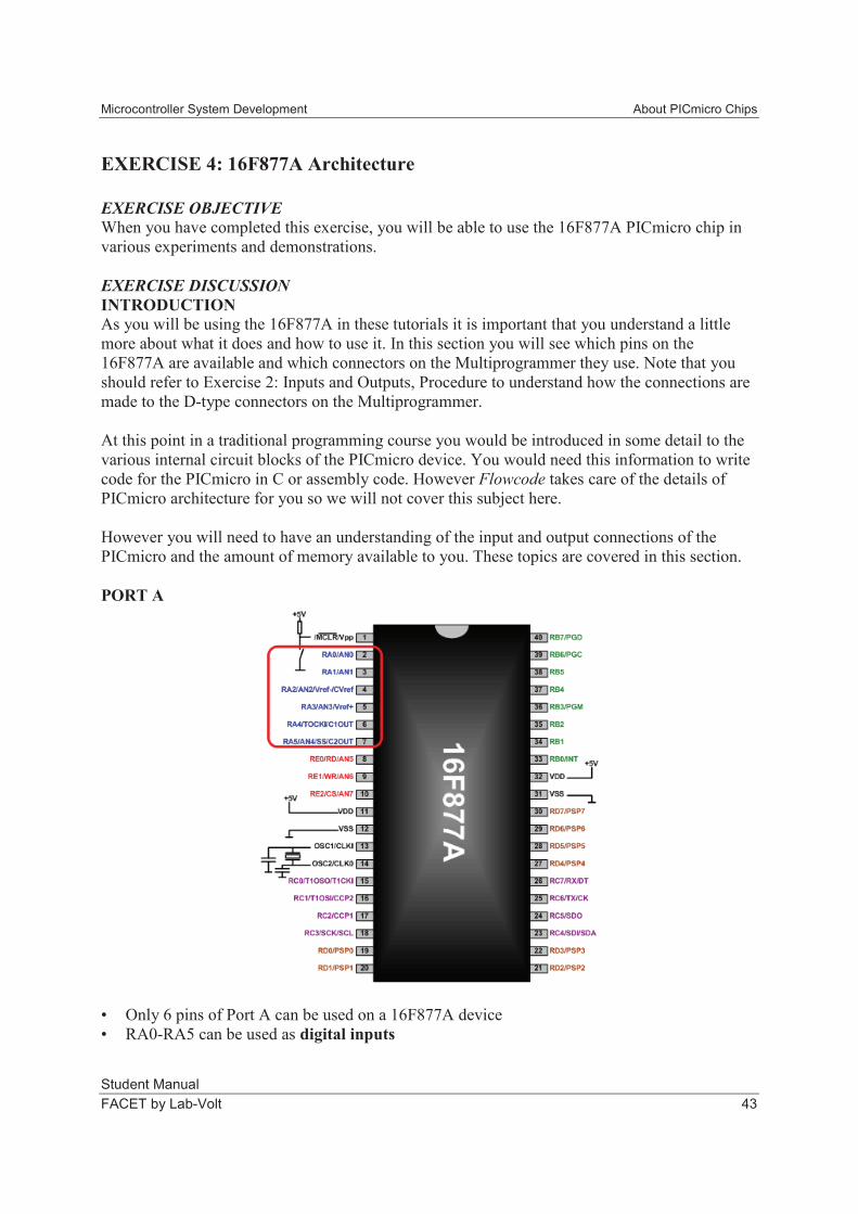
PORT A
• Only 6 pins of Port A can be used on a 16F877A device
• RA0-RA5 can be used as digital inputs
About PICmicro Chips Microcontroller System Development
Student Manual
44 FACET by Lab-Volt
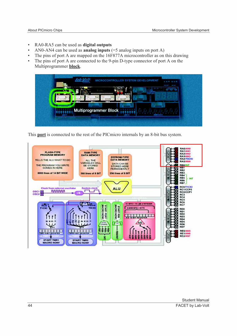
• RA0-RA5 can be used as digital outputs
• AN0-AN4 can be used as analog inputs (=5 analog inputs on port A)
• The pins of port A are mapped on the 16F877A microcontroller as on this drawing
• The pins of port A are connected to the 9-pin D-type connector of port A on the
Multiprogrammer block.
This port is connected to the rest of the PICmicro internals by an 8-bit bus system.
Microcontroller System Development About PICmicro Chips
Student Manual
FACET by Lab-Volt 45
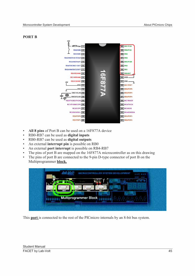
PORT B
• All 8 pins of Port B can be used on a 16F877A device
• RB0-RB7 can be used as digital inputs
• RB0-RB7 can be used as digital outputs
• An external interrupt pin is possible on RB0
• An external port interrupt is possible on RB4-RB7
• The pins of port B are mapped on the 16F877A microcontroller as on this drawing
• The pins of port B are connected to the 9-pin D-type connector of port B on the
Multiprogrammer block.
This port is connected to the rest of the PICmicro internals by an 8-bit bus system.
About PICmicro Chips Microcontroller System Development
Student Manual
46 FACET by Lab-Volt
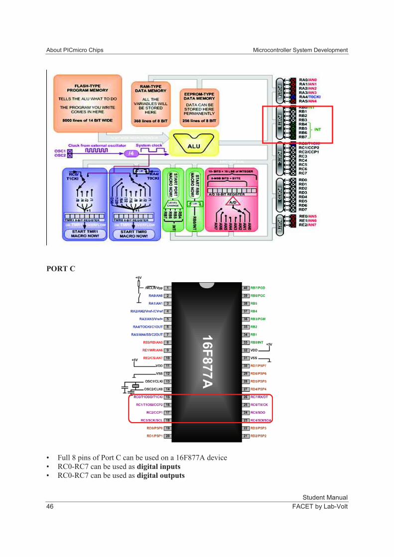
PORT C
• Full 8 pins of Port C can be used on a 16F877A device
• RC0-RC7 can be used as digital inputs
• RC0-RC7 can be used as digital outputs
Microcontroller System Development About PICmicro Chips
Student Manual
FACET by Lab-Volt 47
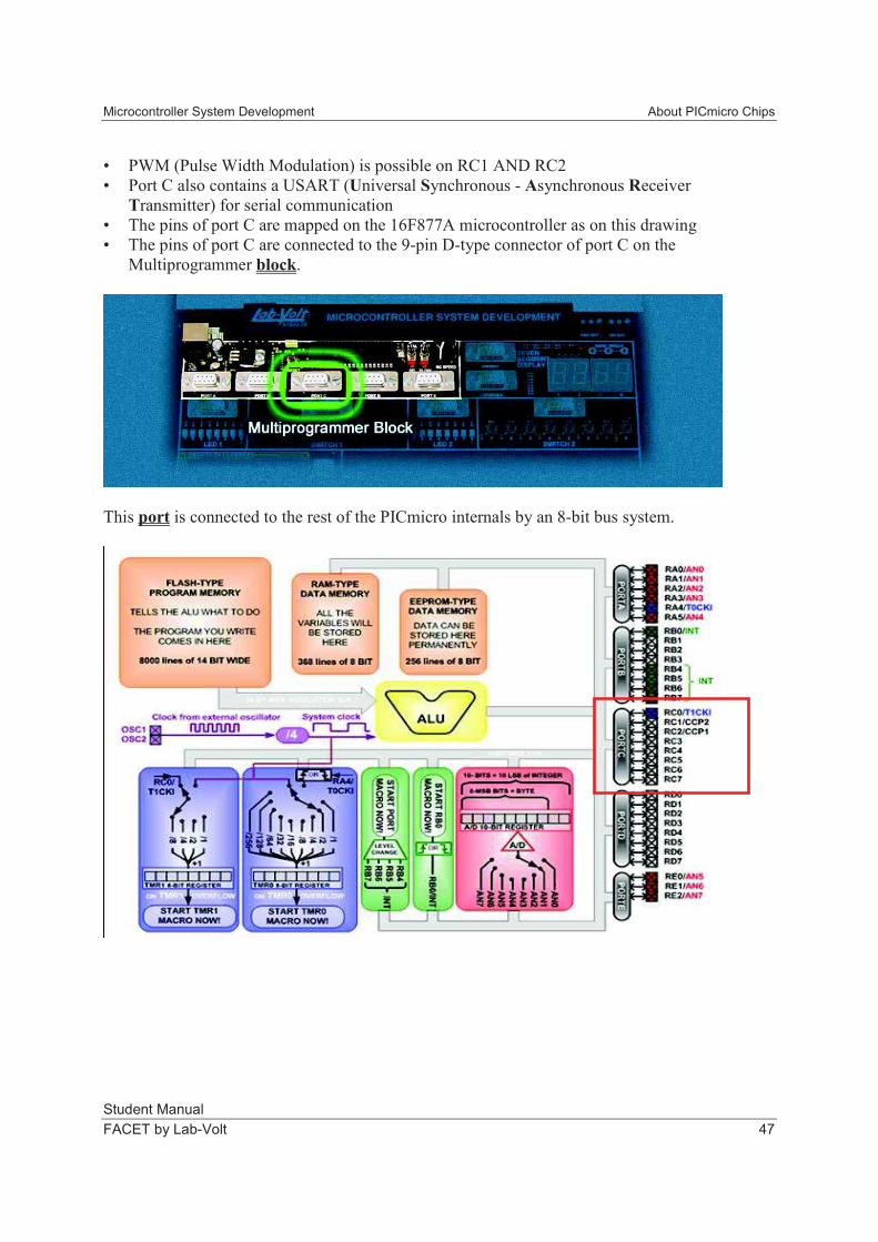
• PWM (Pulse Width Modulation) is possible on RC1 AND RC2
• Port C also contains a USART (Universal Synchronous - Asynchronous Receiver
Transmitter) for serial communication
• The pins of port C are mapped on the 16F877A microcontroller as on this drawing
• The pins of port C are connected to the 9-pin D-type connector of port C on the
Multiprogrammer block.
This port is connected to the rest of the PICmicro internals by an 8-bit bus system.
About PICmicro Chips Microcontroller System Development
Student Manual
48 FACET by Lab-Volt
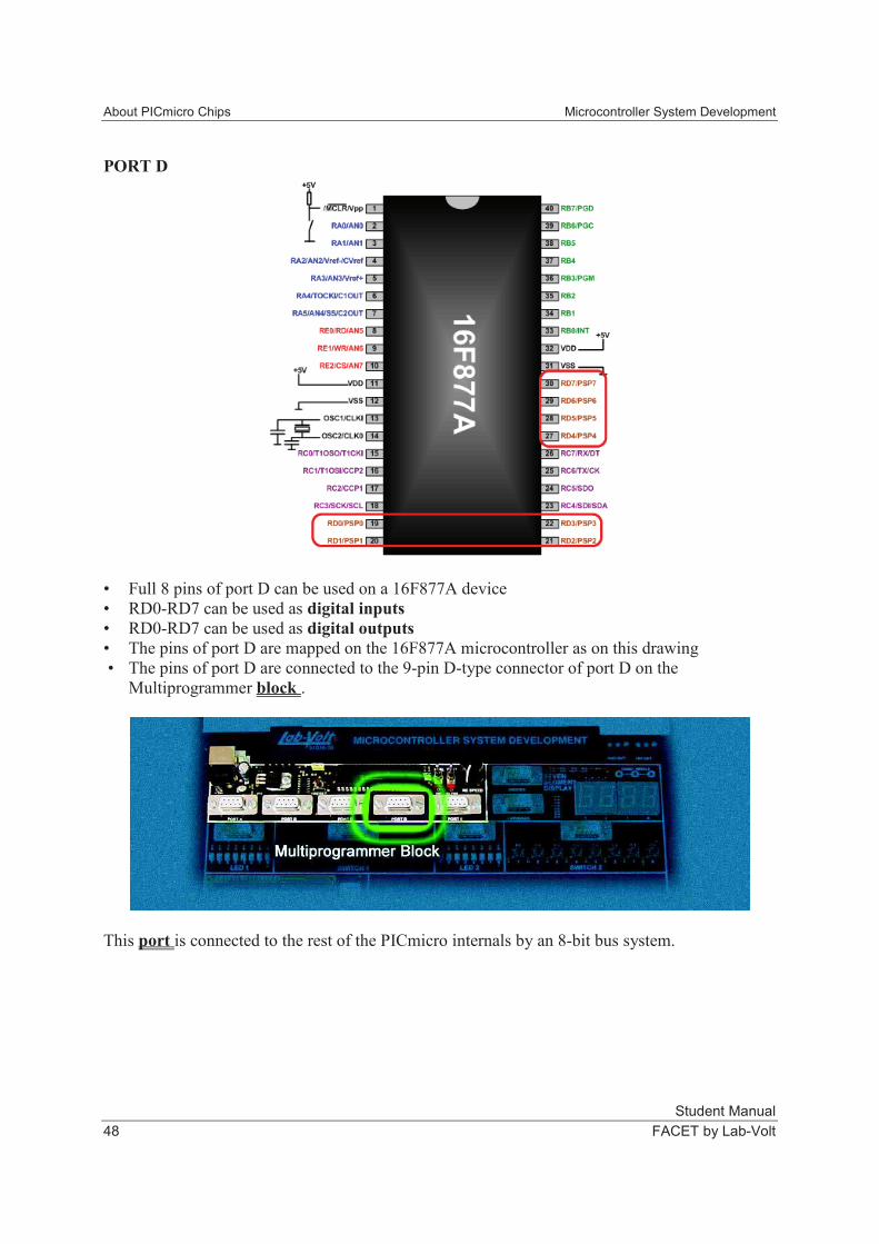
PORT D
• Full 8 pins of port D can be used on a 16F877A device
• RD0-RD7 can be used as digital inputs
• RD0-RD7 can be used as digital outputs
• The pins of port D are mapped on the 16F877A microcontroller as on this drawing
• The pins of port D are connected to the 9-pin D-type connector of port D on the
Multiprogrammer block .
This port is connected to the rest of the PICmicro internals by an 8-bit bus system.
Microcontroller System Development About PICmicro Chips
Student Manual
FACET by Lab-Volt 49
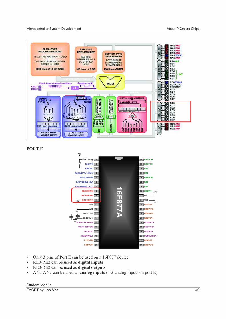
PORT E
• Only 3 pins of Port E can be used on a 16F877 device
• RE0-RE2 can be used as digital inputs
• RE0-RE2 can be used as digital outputs
• AN5-AN7 can be used as analog inputs (= 3 analog inputs on port E)

About PICmicro Chips Microcontroller System Development
Student Manual
50 FACET by Lab-Volt
• The pins of port E are mapped on the 16F877A microcontroller as on this drawing
• The pins of port E are connected to the 9-pin D-type connector of port E on the
Multiprogrammer block.
This port is connected to the rest of the PICmicro internals by an 8-bit bus system.
Flash or EPROM
• EPROM (sometimes referred to as 'Flash') memory is the memory where the program you
write is stored.
• The program you write is 'compiled' by your computer to binary code and then downloaded
into the Flash memory of the PICmicro
• Flash memory is also used in your memory stick or MP3 player. You can read from, and
write to it and it remembers everything, even after a power cut.
• The program lines Flowcode generates tell the PICmicro what to do and when to do it.
• The Flash memory of the 16F877A can store up to 8000 program commands.
Microcontroller System Development About PICmicro Chips
Student Manual
FACET by Lab-Volt 51
RAM
• RAM is the memory where the 'variables' (values in your program that alter as your program
runs) you declare are stored.
• Data from inputs, outputs, analog inputs, calculations etc. is typically stored in variables
inside Flowcode.
• This memory is of the RAM-type. It's erased every time the power gets cut or a reset occurs.
• The RAM of the 16F877A can store up to 368 bytes of data.
EEPROM
• EEPROM is the memory where the variables can be permanently stored.
• This memory is of the PROM-type. It is preserved every time the power gets cut or a reset
occurs.
• The EEPROM of the 16F877A can store up to 256 bytes of data.
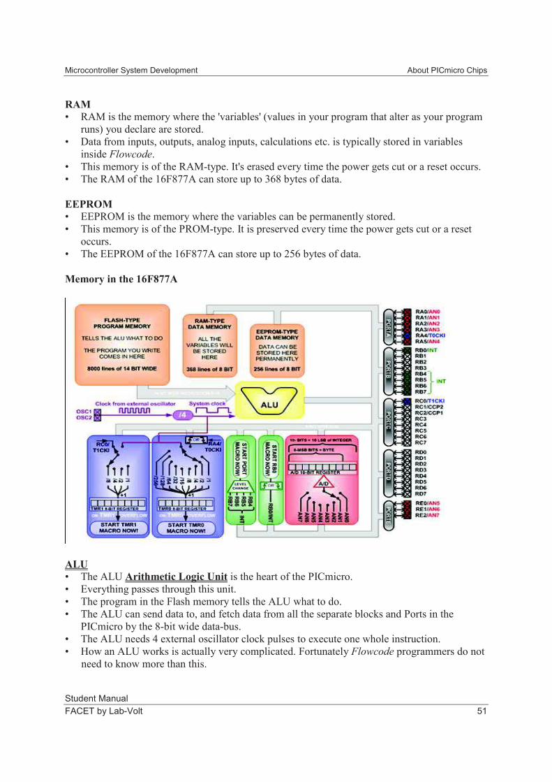
Memory in the 16F877A
ALU
• The ALU Arithmetic Logic Unit is the heart of the PICmicro.
• Everything passes through this unit.
• The program in the Flash memory tells the ALU what to do.
• The ALU can send data to, and fetch data from all the separate blocks and Ports in the
PICmicro by the 8-bit wide data-bus.
• The ALU needs 4 external oscillator clock pulses to execute one whole instruction.
• How an ALU works is actually very complicated. Fortunately Flowcode programmers do not
need to know more than this.
About PICmicro Chips Microcontroller System Development
Student Manual
52 FACET by Lab-Volt
TIMER 1
• This timer interrupt is used to provide the PICmicro with exact timing information.
• It is clocked by the system clock or by an external clock on RC0.
• This system clock runs exactly 4 times slower than the external oscillator clock.
• Either the external clock or the system clock can be divided by 1, 2, 4 or 8 by configuring the
Prescaler of TMR1 in Flowcode.
• This divided clock triggers the TMR1 to increment the TMR1 register.
• This TMR1 register is an 8-bit register and will have an overflow when it reaches 256.
• On the exact moment when this overflow occurs, TMR1 generates an interrupt and the
TMR1 register is set back to 0.
• This TMR1 Interrupt will stop the main program immediately and start up the TMR1 Macro.
• After the TMR1 Macro is finished, the main program continues on from where it had left off.
Example:
External clock oscillator = XTAL : 19,660,800Hz
System Clock = /4 : 4,915,200 Hz
Set prescaler to 8 = /8 : 614,400 Hz
Overflow when TMR1 = 256 = /256 : 2400 Hz
Conclusion: In this situation, TMR1 will interrupt the main program and execute the TMR1
Macro 2400 times per second.
TIMER 0
• This timer interrupt is used to provide the PICmicro with exact timing information.
• It is clocked by the system clock or by an external clock on RA4.
• This system clock runs exactly 4 times slower than the external oscillator clock.
• Either the external clock or the system clock can be divided by 1, 2, 4 or 8, 16, 32, 64, 128,
or by 256 by configuring the Prescaler of TMR0 in Flowcode.
• This divided clock triggers TMR0 to increment the TMR0 register.
• This TMR0 register is an 8-bit register and will have an overflow when it reaches 256.
• On the exact moment when this overflow occurs, TMR0 generates an interrupt and the
TMR0 register is set back to 0.
• This TMR0 Interrupt will stop the main program immediately and start up the TMR0 Macro.
• After the TMR0 Macro is finished, the main program continues on from where it had left off.
Example:
External clock oscillator = XTAL : 19.660.800Hz
System Clock = /4 : 4.915.200 Hz
Set prescaler to 256 = /256 : 19200 Hz
Overflow when TMR0 = 256 = /256 : 75 Hz
Conclusion: In this situation, TMR0 will interrupt the main program and execute the TMR0
macro 75 times per second.
Microcontroller System Development About PICmicro Chips
Student Manual
FACET by Lab-Volt 53
RBO External Interrupt
• A logic level change on RB0 can be configured to generate an interrupt.
• It can be configured in Flowcode to react to a rising or to a falling edge on RB0.
• When it is set to react to a rising edge and a rising edge occurs at RB0 then:
This will immediately stop the main program
The RB0 related macro is executed
After this RBO macro is executed, the main program continues on from where it had left
off.
This will happen every time a rising edge is detected at pin RB0.
PORTB External Interrupt
• A logic level change on either RB4 or RB5 or RB6 or RB7 can be configured to generate one
and the same single interrupt.
• It can not be configured to react to a rising or to a falling edge. It is triggered by both rising
and falling edges.
• When it is configured in Flowcode and a level change occurs on either of these 4 input pins
of Port B:
This will immediately stop the main program
The PORTB related macro is executed
After this PORTB macro is executed, the main program continues on from where it had
left off.
This will happen every time a level change is detected on one of the 4 MSB's of PORTB.
A/D Conversion
• This 16F877A PICmicro Microcontroller has 8 pins that have an extra A/D function.
• This PICmicro controller has only one single 10-bit A/D converter.
• This implies that these 8 analog inputs can't all be read at the same time.
• A built in analog switch is the answer to this problem.
• In Flowcode you can select which of the 8 analog inputs you want to sample.
• After this 'sample' instruction, the analog switch is set to the correct input and this analog
input is converted to a 10-bit binary value.
• In Flowcode, you can select to only use the 8 MSB's of this 10-bit value by using the
'ReadAsByte' instruction, or you can select to use the full 10 bits by selecting the 'ReadAsInt'
instruction. The 10 bits will fill up the 10 LSB's of the selected 16-bit integer variable.
• After this, you can select another analog input that needs to be read.
Busses:
• A PICmicro is a typical Harvard-type Microcontroller.
• This means that there is a separate bus for Instructions and one for Data.
• The data bus is 8-bit wide and connects every block and port together.
• The instruction bus is 14 bit wide and transports 14 bit long instructions from the program
memory to the ALU.

About PICmicro Chips Microcontroller System Development
Student Manual
54 FACET by Lab-Volt
EXERCISE QUESTIONS
The various ports are connected to the rest of the PICmicro internals by a(n) _______ system.
a. 32-bit bus system
b. 16-bit bus system
c. 8-bit bus system
A Harvard-type microcontroller uses
a. the same bus for both instructions and data.
b. one bus for instructions and a separate bus for data.
c. an ACLU data-bus.
Microcontroller System Development About PICmicro Chips
Student Manual
FACET by Lab-Volt 55
EXERCISE PROCEDURE
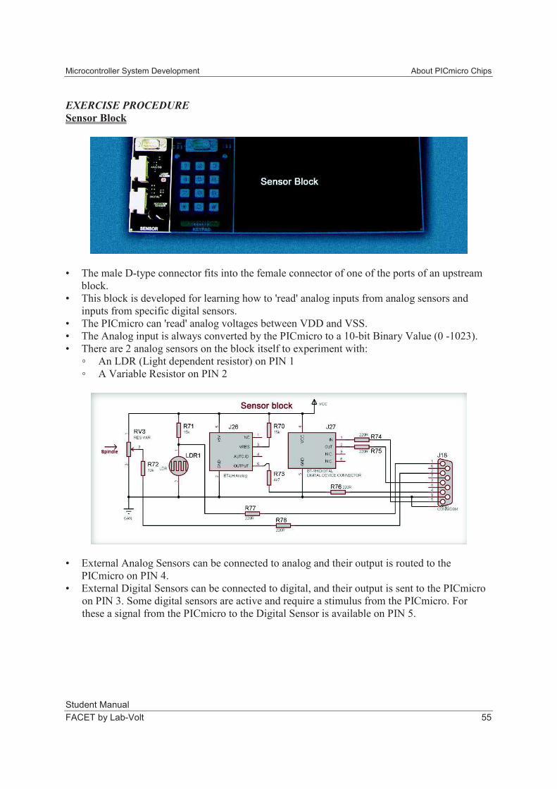
Sensor Block
• The male D-type connector fits into the female connector of one of the ports of an upstream
block.
• This block is developed for learning how to 'read' analog inputs from analog sensors and
inputs from specific digital sensors.
• The PICmicro can 'read' analog voltages between VDD and VSS.
• The Analog input is always converted by the PICmicro to a 10-bit Binary Value (0 -1023).
• There are 2 analog sensors on the block itself to experiment with:
An LDR (Light dependent resistor) on PIN 1
A Variable Resistor on PIN 2
• External Analog Sensors can be connected to analog and their output is routed to the
PICmicro on PIN 4.
• External Digital Sensors can be connected to digital, and their output is sent to the PICmicro
on PIN 3. Some digital sensors are active and require a stimulus from the PICmicro. For
these a signal from the PICmicro to the Digital Sensor is available on PIN 5.
About PICmicro Chips Microcontroller System Development
Student Manual
56 FACET by Lab-Volt
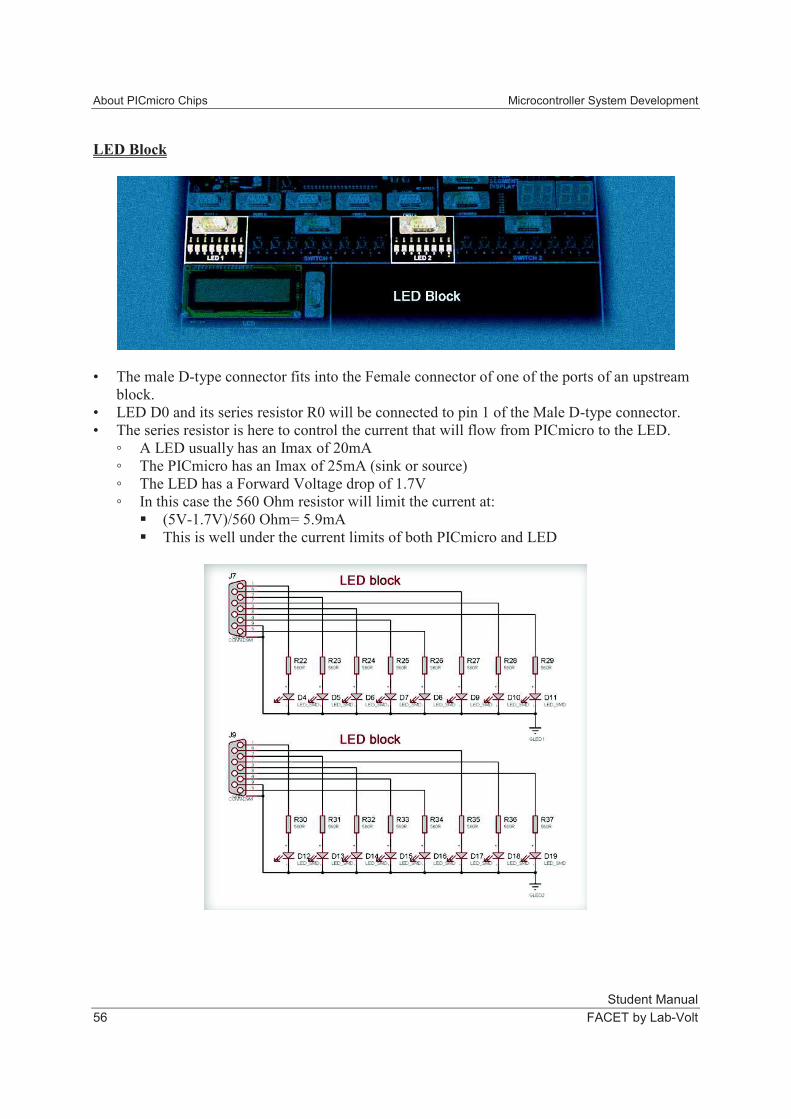
LED Block
• The male D-type connector fits into the Female connector of one of the ports of an upstream
block.
• LED D0 and its series resistor R0 will be connected to pin 1 of the Male D-type connector.
• The series resistor is here to control the current that will flow from PICmicro to the LED.
A LED usually has an Imax of 20mA
The PICmicro has an Imax of 25mA (sink or source)
The LED has a Forward Voltage drop of 1.7V
In this case the 560 Ohm resistor will limit the current at:
(5V-1.7V)/560 Ohm= 5.9mA
This is well under the current limits of both PICmicro and LED
Microcontroller System Development About PICmicro Chips
Student Manual
FACET by Lab-Volt 57
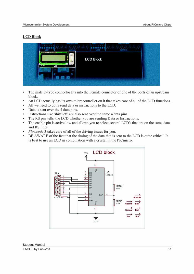
LCD Block
• The male D-type connector fits into the Female connector of one of the ports of an upstream
block.
• An LCD actually has its own microcontroller on it that takes care of all of the LCD functions.
• All we need to do is send data or instructions to the LCD.
• Data is sent over the 4 data pins.
• Instructions like 'shift left' are also sent over the same 4 data pins.
• The RS pin 'tells' the LCD whether you are sending Data or Instructions.
• The enable pin is active low and allows you to select several LCD's that are on the same data
and RS lines.
• Flowcode 3 takes care of all of the driving issues for you.
• BE AWARE of the fact that the timing of the data that is sent to the LCD is quite critical. It
is best to use an LCD in combination with a crystal in the PICmicro.
About PICmicro Chips Microcontroller System Development
Student Manual
58 FACET by Lab-Volt
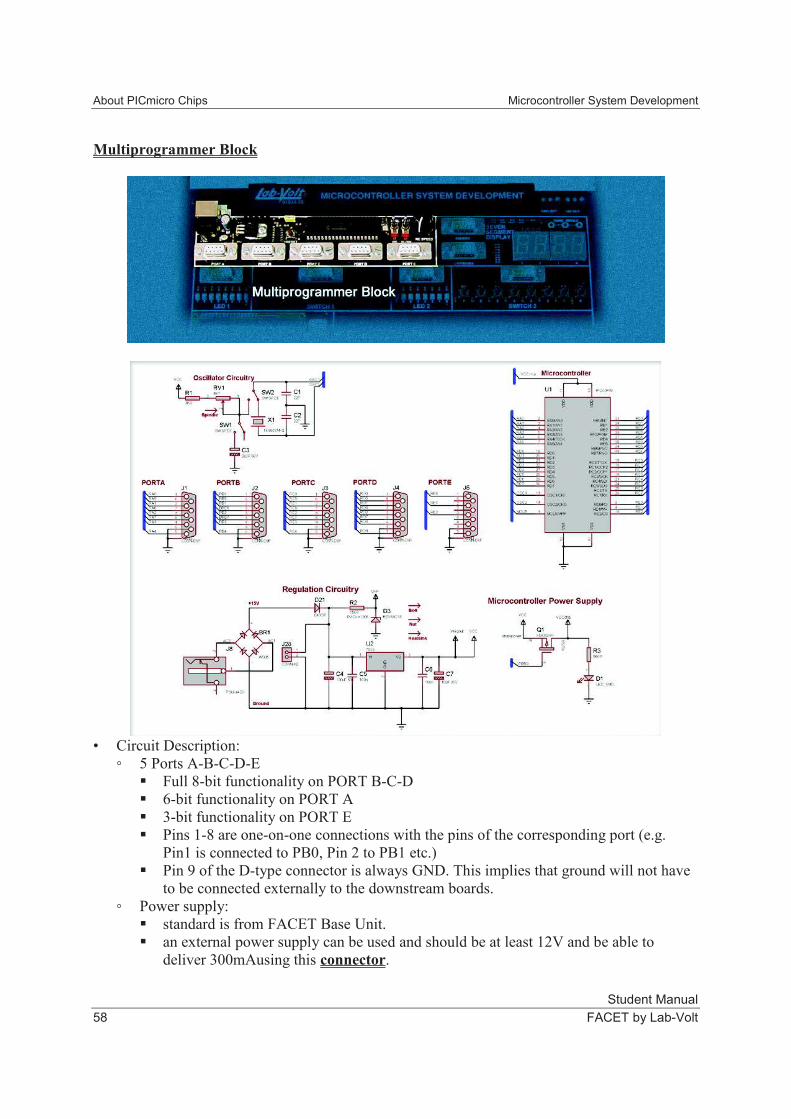
Multiprogrammer Block
• Circuit Description:
5 Ports A-B-C-D-E
Full 8-bit functionality on PORT B-C-D
6-bit functionality on PORT A
3-bit functionality on PORT E
Pins 1-8 are one-on-one connections with the pins of the corresponding port (e.g.
Pin1 is connected to PB0, Pin 2 to PB1 etc.)
Pin 9 of the D-type connector is always GND. This implies that ground will not have
to be connected externally to the downstream boards.
Power supply:
standard is from FACET Base Unit.
an external power supply can be used and should be at least 12V and be able to
deliver 300mAusing this connector.
Microcontroller System Development About PICmicro Chips
Student Manual
FACET by Lab-Volt 59
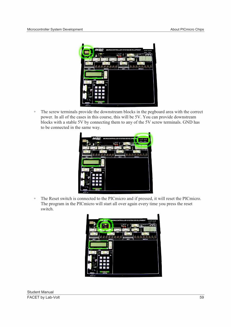
The screw terminals provide the downstream blocks in the pegboard area with the correct
power. In all of the cases in this course, this will be 5V. You can provide downstream
blocks with a stable 5V by connecting them to any of the 5V screw terminals. GND has
to be connected in the same way.
The Reset switch is connected to the PICmicro and if pressed, it will reset the PICmicro.
The program in the PICmicro will start all over again every time you press the reset
switch.
About PICmicro Chips Microcontroller System Development
Student Manual
60 FACET by Lab-Volt
Clocking
Every 4 clock-pulses, the PICmicro executes one single instruction. This implies that
the external clock source that provides the PICmicro with these pulses actually
determines the speed of the execution of the program.
A single instruction is NOT the same as one Flowcode symbol. A Flowcode program
is compiled into C and then into Assembly. One line of Assembly code is called 'a
single instruction.'
Some Flowcode symbols are compiled into only a few assembly lines while others
could easily be compiled into 50 or more assembly lines. You will have to look at the
compiled assembly code to know the exact timing.
XTAL-MODE
For very fast operation: up to 20MHz
In this course we will use a 19,660,800Hz Crystal.
19,660,800 / 1024 = 19200
(19,660,800 / 1024) / 256 = 75
Settings on the Multiprogrammer Block:
Put Toggle switch in XTAL position.
Settings in Flowcode 3:
CHIP...CONFIGURE Select 'XTAL'
RC-MODE
For lower Frequencies - RC is not as stable as Crystal mode
RC SLOW : 10Hz to 25Hz (Can be Changed by RV1)
RC FAST : 600kHz to 1200kHz (Can be Changed by RV1)
Settings on the Multiprogrammer Block:
Put Toggle switch in RC position.
Another Toggle switch is used to select SLOW or FAST.
Settings in Flowcode 3:
CHIP...CONFIGURE Select 'RC'
Microcontroller System Development About PICmicro Chips
Student Manual
FACET by Lab-Volt 61
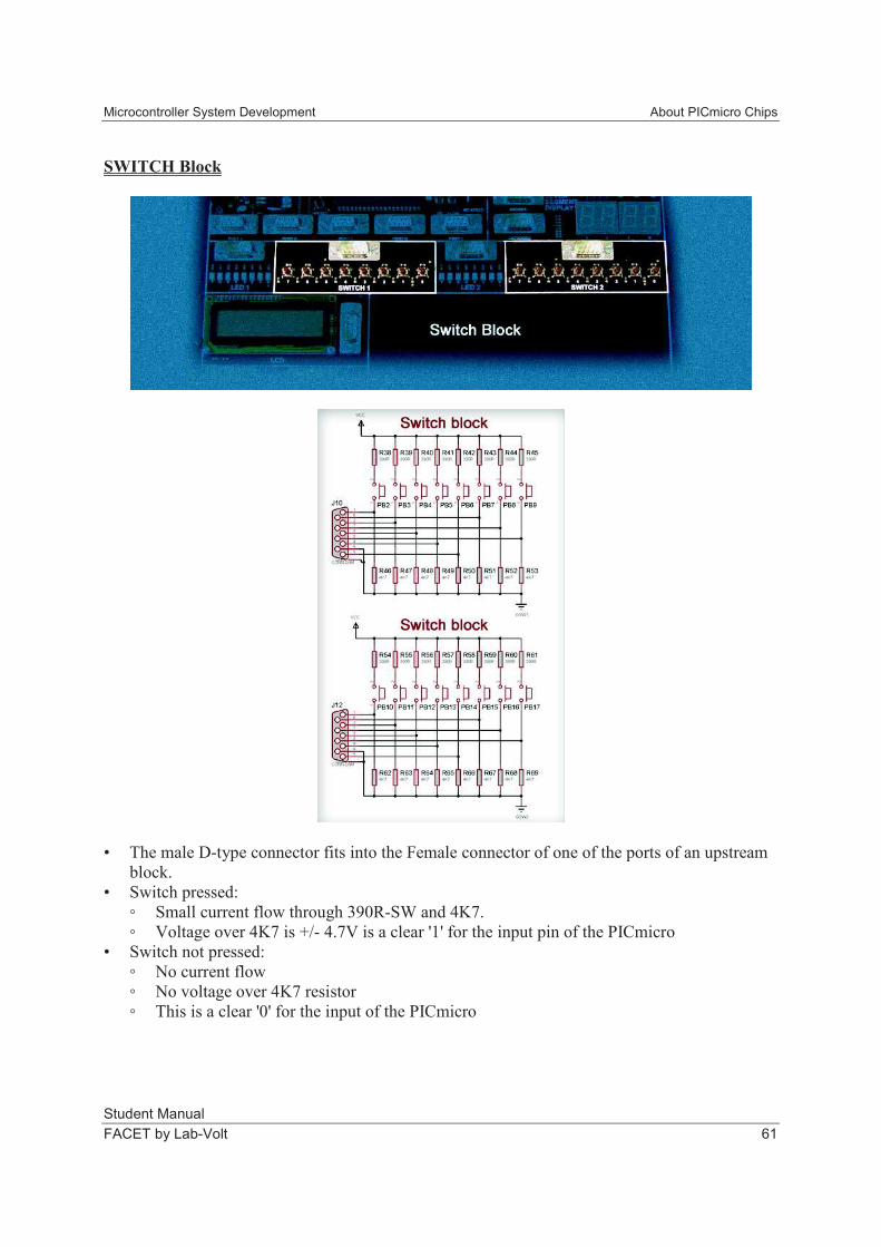
SWITCH Block
• The male D-type connector fits into the Female connector of one of the ports of an upstream
block.
• Switch pressed:
Small current flow through 390R-SW and 4K7.
Voltage over 4K7 is +/- 4.7V is a clear '1' for the input pin of the PICmicro
• Switch not pressed:
No current flow
No voltage over 4K7 resistor
This is a clear '0' for the input of the PICmicro
About PICmicro Chips Microcontroller System Development
Student Manual
62 FACET by Lab-Volt
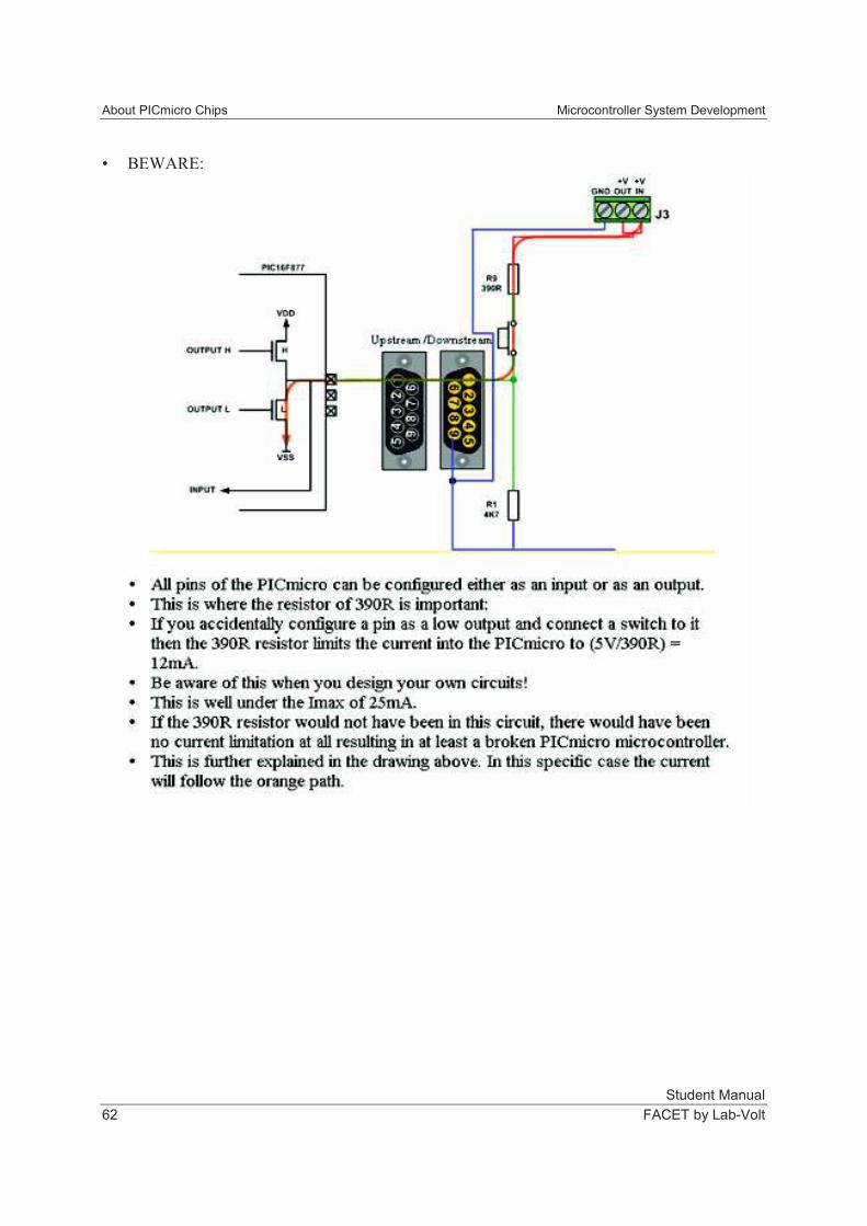
• BEWARE:
Microcontroller System Development About PICmicro Chips
Student Manual
FACET by Lab-Volt 63
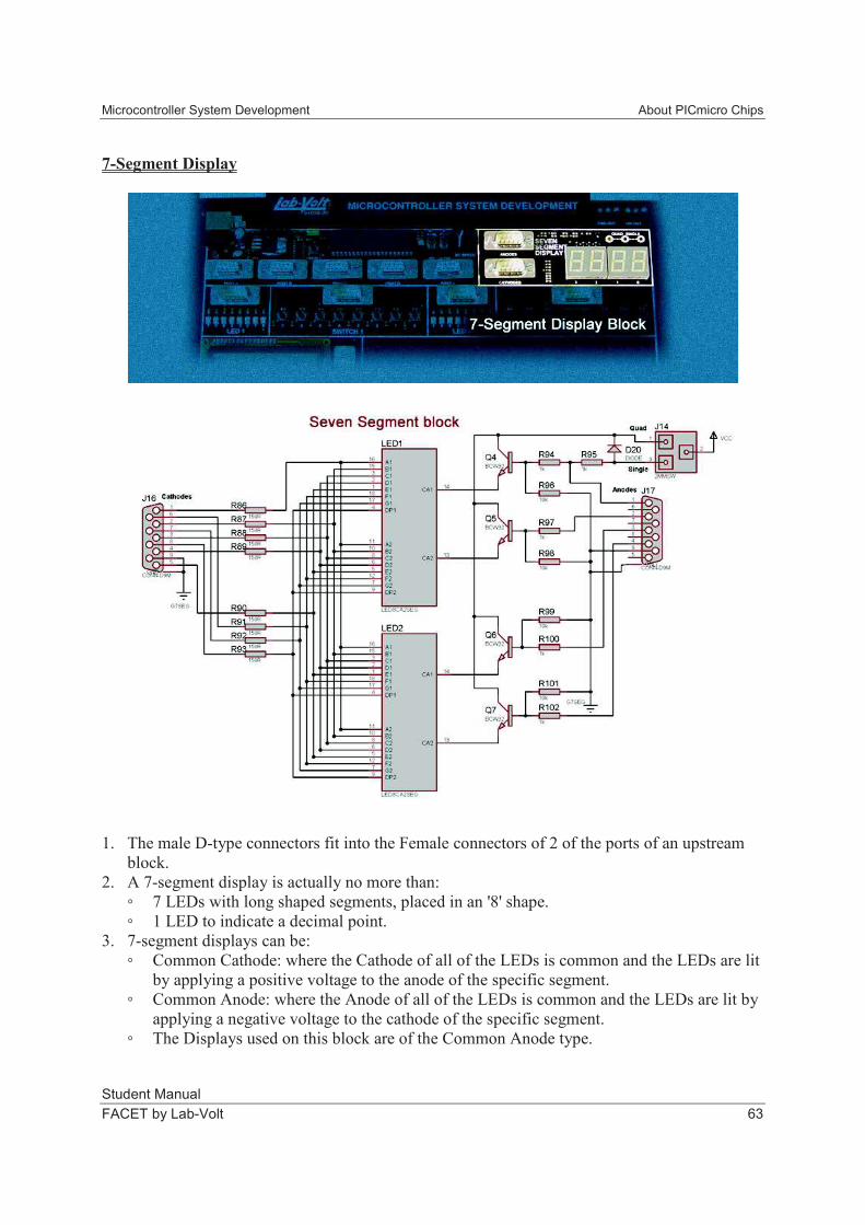
7-Segment Display
1. The male D-type connectors fit into the Female connectors of 2 of the ports of an upstream
block.
2. A 7-segment display is actually no more than:
7 LEDs with long shaped segments, placed in an '8' shape.
1 LED to indicate a decimal point.
3. 7-segment displays can be:
Common Cathode: where the Cathode of all of the LEDs is common and the LEDs are lit
by applying a positive voltage to the anode of the specific segment.
Common Anode: where the Anode of all of the LEDs is common and the LEDs are lit by
applying a negative voltage to the cathode of the specific segment.
The Displays used on this block are of the Common Anode type.
About PICmicro Chips Microcontroller System Development
Student Manual
64 FACET by Lab-Volt
4. The tricky bit is that we do not have enough pins to drive all these LEDs (8 x 4 = 32 separate
LEDs) by our controller. We will solve this by:
Using the speed of the PICmicro.
By driving pin 1-2-3 or 4 of the anodes connector we determine which of the four 7-
segment displays is active to receive data.
Data is sent to the active display by the 8 data pins on the cathodes connector.
LEDs will emit light for a short time after they have been turned off.
So the trick is that you alternately activate each of the four 7 segment displays in turn, by
making the appropriate anode high, and then send the data to each display by making the
appropriate cathodes low.
5. If you only need a single display, then this can be activated permanently by putting a two-
post connector in the single location above the displays. This way only the cathode connector
is used to drive the left display and no multiplexing is necessary.
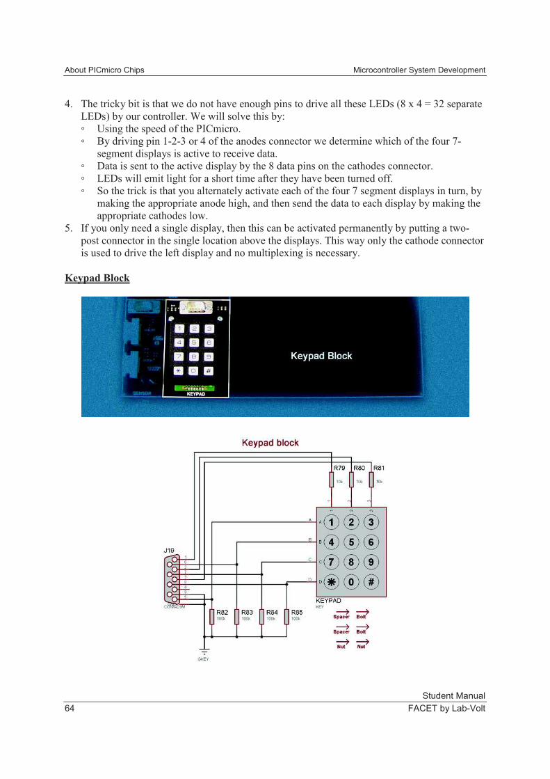
Keypad Block
Microcontroller System Development About PICmicro Chips
Student Manual
FACET by Lab-Volt 65
6. This Keypad input block provides you with 12 input buttons on an 8-bit port.
• This is done by alternately making the column lines high and then scanning the 4 row input
lines.
• If one of the row inputs reads as high, you know which button was pushed.
• This is called a 'multiplexed input'.
• Flowcode provides the programmer with a hardware macro that takes care of this all.
• The keypad is best connected to port B because this port has a Port interrupt on the lines
RB4-RB7, exactly the same lines as the row connections.
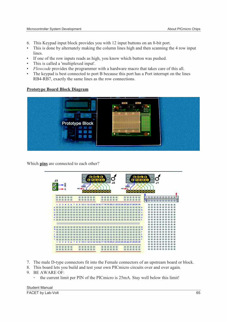
Prototype Board Block Diagram
Which pins are connected to each other?
7. The male D-type connectors fit into the Female connectors of an upstream board or block.
8. This board lets you build and test your own PICmicro circuits over and over again.
9. BE AWARE OF:
the current limit per PIN of the PICmicro is 25mA. Stay well below this limit!
About PICmicro Chips Microcontroller System Development
Student Manual
66 FACET by Lab-Volt
Connecting input devices on pins that are configured as outputs (see switch block)
The total current limit of the PICmicro (all of the pins) is 200mA.
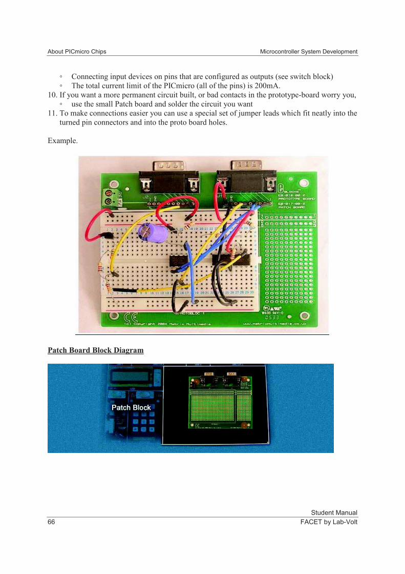
10. If you want a more permanent circuit built, or bad contacts in the prototype-board worry you,
use the small Patch board and solder the circuit you want
11. To make connections easier you can use a special set of jumper leads which fit neatly into the
turned pin connectors and into the proto board holes.
Example.
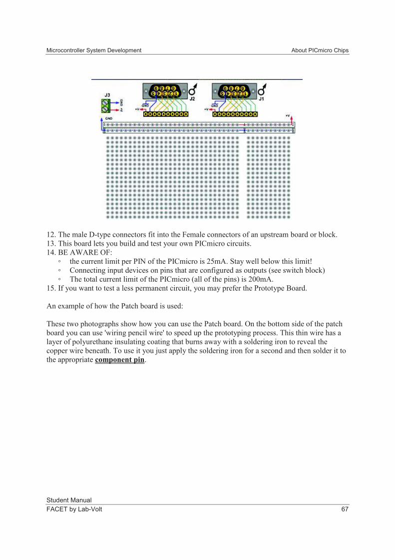
Patch Board Block Diagram
Microcontroller System Development About PICmicro Chips
Student Manual
FACET by Lab-Volt 67
12. The male D-type connectors fit into the Female connectors of an upstream board or block.
13. This board lets you build and test your own PICmicro circuits.
14. BE AWARE OF:
the current limit per PIN of the PICmicro is 25mA. Stay well below this limit!
Connecting input devices on pins that are configured as outputs (see switch block)
The total current limit of the PICmicro (all of the pins) is 200mA.
15. If you want to test a less permanent circuit, you may prefer the Prototype Board.
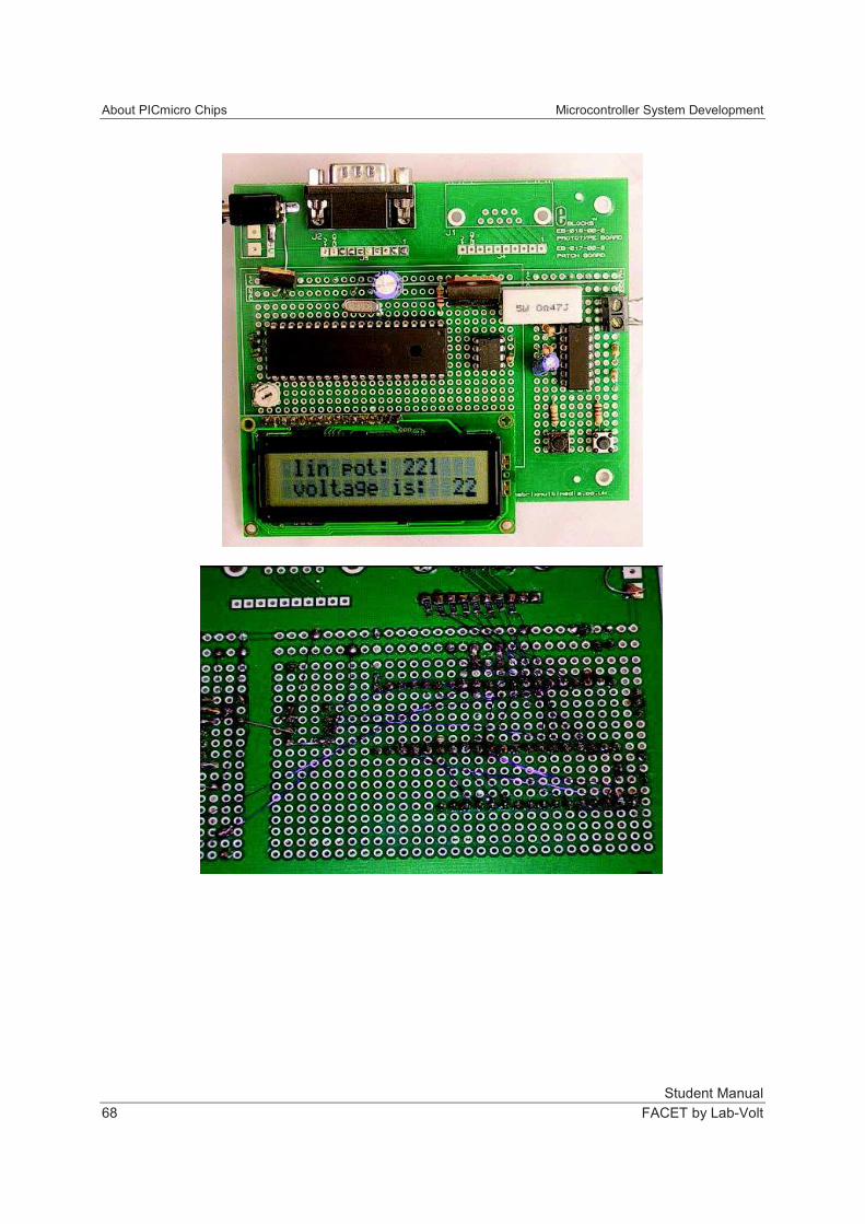
An example of how the Patch board is used:
These two photographs show how you can use the Patch board. On the bottom side of the patch
board you can use 'wiring pencil wire' to speed up the prototyping process. This thin wire has a
layer of polyurethane insulating coating that burns away with a soldering iron to reveal the
copper wire beneath. To use it you just apply the soldering iron for a second and then solder it to
the appropriate component pin.
About PICmicro Chips Microcontroller System Development
Student Manual
68 FACET by Lab-Volt
Microcontroller System Development About PICmicro Chips
Student Manual
FACET by Lab-Volt 69
REVIEW QUESTIONS
1. The Sensor Block has two ___________ sensors to experiment with - a Light Dependent
resistor (LDR) and a Variable Resistor.
a. digital
b. analog
c. digital to analog
2. Every time you press the reset switch on the PICmicro it will start the program at the
previous step.
a. True
b. False
EXERCISE CONCLUSION
• Each pin on the PICmicro chip has specific characteristics, availability for digital or analog
data and connection to the entire system.
• The PICmicro chip uses EPROM, RAM, and EEProm memory.
• The ALU (Arithmetic Logic Unit) is at the heart of the PICmicro - everything passes through
it.
• The timer interrupt provides the PICmicro with exact timing and PORT B enables external
interrupt of activities.
• This model of the PICmicro chip also has an A/D Converter.
REVIEW QUESTIONS
1. The pins at each port on the PICmicro chip have the same capabilities.
a. True
b. False
2. The program you write for the PICmicro is stored in the EPROM or Flash memory of the
chip.
a. True
b. False
3. The ALU can:
a. send data.
b. fetch data.
c. send or fetch data.
d. compile the program.
4. The PICmicro controller has a 10-bit A/D converter that permits:
a. reading of one input at a time.
b. reading of multiple inputs at one time.
c. reading of 16-bit information only.
d. The A/D converter is not capable of reading anything.

About PICmicro Chips Microcontroller System Development
Student Manual
70 FACET by Lab-Volt
5. The PICmicro is a(n):
a. Columbia-type controller.
b. Intel-type controller.
c. HP-type controller.
d. Harvard-type controller.
CMS AVAILABLE
FAULTS AVAILABLE