Embed Size (px)
Citation preview

Exercise 3-11 Determine the Thevenin-equivalent circuit at terminals (a,b) in Fig. E3-11.
Solution:
(1) Open-circuit voltage
We apply node voltage method to determine open-circuit voltage:
V1
2−4+
V1−V2
3= 0,
V2−V1
3+3+
V2
5= 0.
Solution gives: V2 =−3.5 V.Hence,
VTh = Voc =−3.5 V.
(2) Short-circuit current
Fawwaz T. Ulaby and Michel M. Maharbiz, Circuits c© 2013 National Technology Press

Because of the short circuit,V2 = 0.
Hence at node V1:
V1
2−4+
V1
3= 0
V1
(12
+13
)= 4
V1 =245
V
I1 =V1
3=
245×3
=85
A,
Isc = I1−3 =85−3 =−7
5=−1.4 A
RTh =VTh
Isc=−3.5−1.4
= 2.5 Ω.
Thevenin equivalent:
Fawwaz T. Ulaby and Michel M. Maharbiz, Circuits c© 2013 National Technology Press

Exercise 3-12 Find the Thevenin equivalent of the circuit to the left of terminals (a,b) in Fig. E3-12, andthen determine the current I.
Figure E3-12
Solution: Since the circuit has no dependent sources, we will apply multiple steps of source transformation tosimplify the circuit.
Fawwaz T. Ulaby and Michel M. Maharbiz, Circuits c© 2013 National Technology Press

Across (a,b),
VTh = Voc =10×312+3
= 2 V
RTh = 3 ‖ 12+0.6
=3×123+12
+0.6 = 3 Ω
Hence,
I =2
3+1= 0.5 A.
Fawwaz T. Ulaby and Michel M. Maharbiz, Circuits c© 2013 National Technology Press

Exercise 3-13 Find the Norton equivalent at terminals (a,b) of the circuit in Fig. E3-13.
Figure E3-13
Solution: Thevenin voltage
At node 1:I = 2 A.
Hence,VTh = Voc = 10I−3×3I = I = 2 V.
Next, we determine the short-circuit current:
Fawwaz T. Ulaby and Michel M. Maharbiz, Circuits c© 2013 National Technology Press

At node V1:
−2−3I +V1
10+
V1
3= 0.
Also,
I =V1
10.
Hence,
−2−3I + I +103
I = 0,
which gives
I = 1.5 A,
I1 = 2+3I− I = 2+2I = 5 A,
Isc = 5−3I = 5−4.5 = 0.5 A.
RTh =VTh
Isc=
20.5
= 4 Ω.
Norton circuit is:
Fawwaz T. Ulaby and Michel M. Maharbiz, Circuits c© 2013 National Technology Press

Exercise 3-14 The bridge circuit of Fig. E3-14 is connected to a load RL between terminals (a,b). ChooseRL such that maximum power is delivered to RL. If R = 3 Ω, how much power is delivered to RL?
Figure E3-14
Solution: We need to remove RL and then determine the Thevenin equivalent circuit at terminals (a,b).Open-circuit voltage:
The two branches are balanced (contain same total resistance of 3R). Hence, identical currents will flow, namely
I1 = I2 =243R
=8R
.
Voc = Va−Vb = 2RI1−RI2 = RI1 = R8R
= 8 V.
To find RTh, we replace the source with a short circuit:
Fawwaz T. Ulaby and Michel M. Maharbiz, Circuits c© 2013 National Technology Press
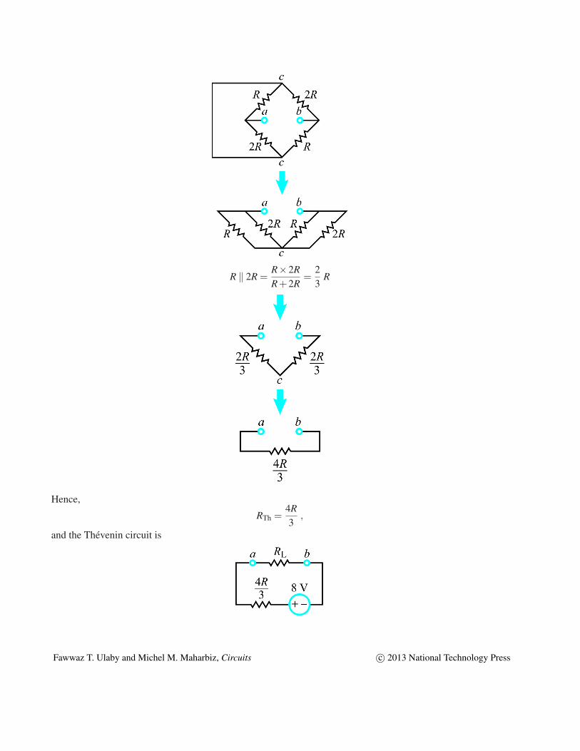
R ‖ 2R =R×2RR+2R
=23
R
Hence,
RTh =4R3
,
and the Thevenin circuit is
Fawwaz T. Ulaby and Michel M. Maharbiz, Circuits c© 2013 National Technology Press

For maximum power transfer with R = 3 Ω, RL should be
RL =4R3
=4×3
3= 4 Ω,
and
Pmax =υ2
s
4RL=
82
4×4= 4 W.
Fawwaz T. Ulaby and Michel M. Maharbiz, Circuits c© 2013 National Technology Press

Exercise 4-7 Express υo in terms of υ1, υ2 and υ3 for the circuit in Fig. E4-7.
Figure E4-7
Solution: Starting from the output of the second stage and moving backwards towards the inputs,
υo =(−10×103
5×10³
)[(− 3×10³
0.5×10³
)υ1 +
(−3×10³
103
)υ2 +
(−3×10³
2×10³
)υ3
]= 12υ1 +6υ2 +3υ3.
Fawwaz T. Ulaby and Michel M. Maharbiz, Circuits c© 2013 National Technology Press

Problem 4.10 In the circuit of Fig. P4.10, a bridge circuit is connected at the inputside of an inverting op-amp circuit.
(a) Obtain the Thevenin equivalent at terminals(a,b) for the bridge circuit.
(b) Use the result in (a) to obtain an expression forG = υo/υs.
(c) EvaluateG for R1 = R4 = 100Ω, R2 = R3 = 101Ω, andRf = 100 kΩ.
υo
υs
R2
b
a
Rf
R1
R4R3
+
_
+_
Figure P4.10: Circuit for Problem 4.10.
Solution: (a) The Thevenin equivalent circuit at(a,b):
vs
R2
b
a
R1
R4R3
+_
i1
i2
+
_
voc
υs+ i1(R1 +R2) = 0
ori1 =
−υs
R1 +R2.
Also,−υs+ i2(R3 +R4) = 0
andi2 =
υs
R3 +R4.
υTh = υoc = i1R2 + i2R4
=−υsR2
R1 +R2+
υsR4
R3 +R4=
[R4(R1 +R2)−R2(R3 +R4)]υs
(R1 +R2)(R3 +R4). (1)
Suppressingυs (by replacing it with a short circuit) leads to
RTh = (R1 ‖ R2)+(R3 ‖ R4)
=R1R2
R1 +R2+
R3R4
R3 +R4=
R1R2(R3 +R4)+R3R4(R1 +R2)
(R1 +R2)(R3 +R4).
(b) For the new circuit:
All rights reserved. Do not reproduce or distribute.c©2013 National Technology and Science Press

vo
vTh
Rf
RTh
+
_
+
_
υo = −Rf
RThυTh (inverting amplifier) (3)
Inserting Eqs. (1) and (2) into (3) leads to
G =υo
υs=
−Rf [R4(R1 +R2)−R2(R3 +R4)]
R1R2(R3 +R4)+R3R4(R1 +R2)
(c) For R1 = R4 = 100Ω, R2 = R3 = 101Ω, andRf = 105 Ω,
G =−105[100(100+101)−101(100+101)]
100×101(100+101)+100×101(100+101)
= 4.9505≃ 5.
All rights reserved. Do not reproduce or distribute.c©2013 National Technology and Science Press

Problem 4.11 Determine the output voltage for the circuit in Fig. P4.11 and specifythe linear range forυs, given thatVcc = 15 V andV0 = 0.
Figure P4.11: Circuit for Problem 4.11.
vo
vsV0
100 kΩ
200 kΩ
2 kΩ
Vcc = 15 V+
+_
_
R1 R2
Inverting Amp
υ1
+R3
R4
υ2
_
Solution: The given circuit is the same as the difference amplifier circuit of Table4-3, with:
R2 = 200 kΩ, R1 = 2 kΩ, R3 = 100 kΩ,
R4 = ∞, υ1 = υs, υ2 = V0 = 0.
Applying the difference amplifier equation given by Eq. (4.41),
υo =
(
R4
R3 +R4
)(
R1 +R2
R1
)
υ2−
(
R2
R1
)
υ1
= −
(
200×103
2×10³
)
υs = −100υs.
Since|(υo)max| = 15 V, the linear range ofυs is
|υs| ≤15100
= 150 mV,
or−150 mV≤ υs ≤ 150 mV.
All rights reserved. Do not reproduce or distribute.c©2013 National Technology and Science Press

Problem 4.23 For the circuit in Fig. P4.23, obtain an expression for voltage gainG = υo/υs.
+
_ 6 kΩ
10 kΩ
4 kΩ
υs
+_
υ0
5 kΩ
Figure P4.23: Circuit for Problem 4.23.
Solution: By voltage division,
υp = υs6
4+6= 0.6υs.
υn = υp = 0.6υs.
υn−υs
10k+
υn−υo
5k= 0.
Simplification leads toυo = 0.4υs.
Hence,
G =υ0
υs= 0.4.
All rights reserved. Do not reproduce or distribute.c©2013 National Technology and Science Press

Problem 4.24 Find the value of υo in the circuit in Fig. P4.24.
+_
υ0
2 A
5 V
2 kΩ
6 kΩ
6 kΩ
+
_
4 kΩ
Figure P4.24: Circuit for Problem 4.24.
Solution: Converting the input current source into a voltage source leads to
+_
υoυnυ1
4 V
5 V
2 kΩ
6 kΩ
6 kΩ
+
_
4 kΩ
+
_
Fig. P4.24(a)
Apply nodal analysis:
υp = υn = 5 V.
@ υn :υn −υ1
6 kΩ+
υn −υo
6 kΩ= 0,
@ υ1 :υ1 −42 kΩ
+υ1 −υo
4 kΩ+
υ1 −υn
6 kΩ= 0.
Simplify:
16k
(υ1 +υo) =10
6 kΩ,
(
12k
+1
4k+
16k
)
υ1 −14k
υo =17
6000,
[ 16k
16k
1112k − 1
4k
][
υ1
υo
]
=
[106k
176k
]
,
[
υ1
υo
]
=
[327
387
]
.
υo = 5.429 V.
All rights reserved. Do not reproduce or distribute. c©2013 National Technology and Science Press
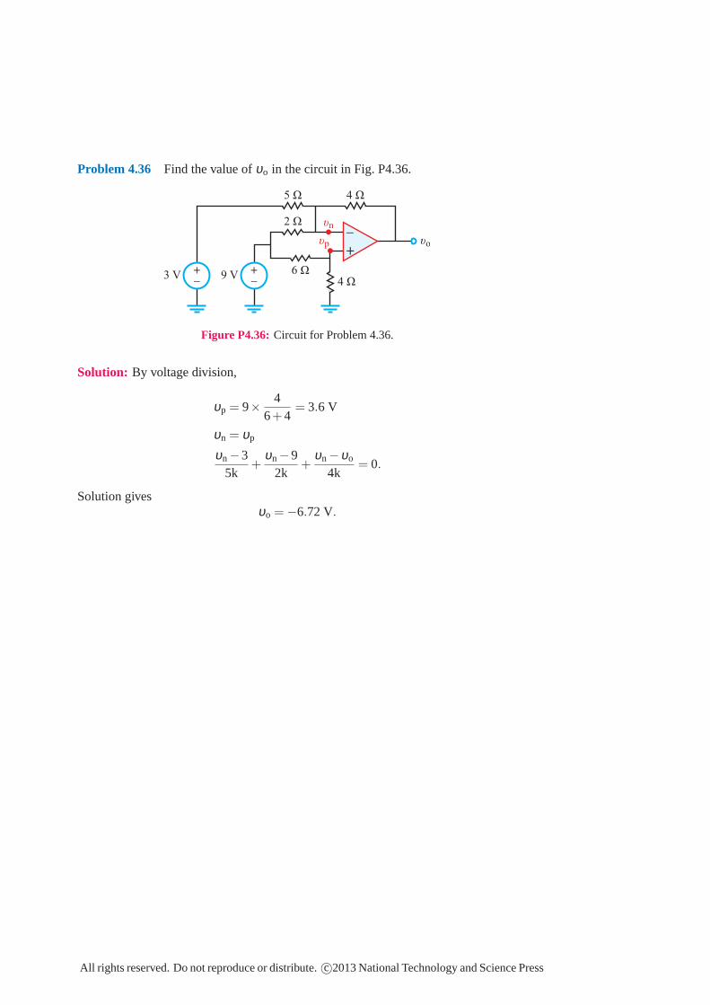
Problem 4.36 Find the value of υo in the circuit in Fig. P4.36.
4 Ω
6 Ω
2 Ω υn
+_
υo
5 Ω 4 Ω
+
_
+
_ 9 V3 V
υp
Figure P4.36: Circuit for Problem 4.36.
Solution: By voltage division,
υp = 9×4
6+4= 3.6 V
υn = υp
υn −35k
+υn −9
2k+
υn −υo
4k= 0.
Solution givesυo = −6.72 V.
All rights reserved. Do not reproduce or distribute. c©2013 National Technology and Science Press

Problem 4.38 Determine υo and the power dissipated in RL in the circuit ofFig. P4.38.
2 Ω
7 Ω
3 Ω4 V
2 V
+_
4 Ω 2 Ω
5 Ω
+
_
+_
υo
RL
3 Ω
Req
υaυp
υn
Figure P4.38: Circuit for Problem 4.38.
Solution: By voltage division,
υp = 4×3k
2k+3k=
125
= 2.4 V
υn −27k
+υn −υa
5k= 0
υn = υp = 2.4 V.
Solution givesυa = 2.686 V.
The 2-kΩ and 4-kΩ output resistors are equivalent to a single resistor
Req =2×42+4
k =86
kΩ.
By voltage division,
υo = υaReq
3k+Req
=2.686×
(
86 k
)
3k+ 86 k
= 0.826 V.
PRL =υ2
o
RL=
(0.826)2
2k= 0.34 mW.
All rights reserved. Do not reproduce or distribute. c©2013 National Technology and Science Press

Problem 4.52 Find the value ofυo in the circuit in Fig. P4.52.
+
_
υo+_
9 V 5 V 8 kΩ
3 kΩ
4 kΩ
3 kΩ
6 kΩ
+
_
+_
8 kΩυn2
υa
υn1
υp2
υp1
i1
i2
i3
Figure P4.52: Circuit for Problem 4.52.
Solution: For the first stage:
υp1= 0 υn1 = 0,
υn1 −98k
+υn1 −υa
6k+
υn1 −υo
3k= 0,
which simplifies to8υo +4υa +27= 0. (1)
For the second stage:
υp2=
5×83+8
=4011
V,
υn2 = υp2=
4011
V.
Sincein2 = 0, υa = υn2 = 4011 V.
Hence,
υ0 =−27−4υa
8
=18
(
−27−4×4011
)
= −5.19 V.
All rights reserved. Do not reproduce or distribute.c©2013 National Technology and Science Press

Exercise 5-9 Determine Ceq and Veq(0) at terminals (a,b) for the circuit in Fig. E5-9, given thatC1 = 6 µF, C2 = 4 µF and C3 = 8 µF, and the initial voltages on the three capacitors are υ1(0) = 5 V andυ2(0) = υ3(0) = 10 V.
Figure E5-9
Solution:
Ceq =C1(C2 ‖C3)C1 +C2 +C3
=C1(C2 +C3)C1 +C2 +C3
=6×10⁻⁶(4×10⁻⁶ +8×10⁻⁶)
(6+4+8)×10−6 = 4 µF,
Veq(0) = υ1(0)+υ2(0) = 5+10 = 15 V.
Fawwaz T. Ulaby and Michel M. Maharbiz, Circuits c© 2013 National Technology Press

Problem 5.19 For the circuit in Fig. P5.19, findCeq at terminals(a,b). Assume allinitial voltages to be zero.
Solution:
a
b
c
d
5 F 3 F 5 F
5 F3 F
6 F 6 F
a
b
5 F
6 F ( )13
+13
16
+65
= F
−1
a
b
5 F
a
b
6 + = F 65
365
Ceq=5× 36
5
5+ 365
=18061
= 2.95 F
Figure P5.19
All rights reserved. Do not reproduce or distribute.c©2013 National Technology and Science Press

Problem 5.20 Find Ceq at terminals (c,d) in the circuit of Fig. P5.19.
Solution:
a
b
c
d
5 F 3 F 5 F
5 F3 F
6 F 6 F
c
d
5 F
5 F
6 F
c
d
5 F
5 F
c
d
( )13
+13
16
+65
= F
−1
( )15
15
536
+ + = 1.86 F
−1
6 + = F 65
365
Figure P5.20
All rights reserved. Do not reproduce or distribute. c©2013 National Technology and Science Press

Exercise 5-13 Determine Leq at terminals (a,b) in the circuit of Fig. E5-13.
Figure E5-13
Solution:
Leq = 2 mH+(6 mH ‖ 12 mH)
=(
2+6×126+12
)mH
= 6 mH.
Fawwaz T. Ulaby and Michel M. Maharbiz, Circuits c© 2013 National Technology Press

Problem 5.30 All elements in Fig. P5.30 are 10-mH inductors. Determine Leq.
Solution:
L
L
L L L
L
L
L
L
L 2L2LLeq
Leq
L
L
LLeq
Leq Leq = 2.5L = 25 mH
( )1
L
L
2
1
2L
1
2L+ + =
−1
Figure P5.30
All rights reserved. Do not reproduce or distribute. c©2013 National Technology and Science Press