Embed Size (px)
Citation preview

LAB ONE– IntroductionIn this lab you will get familiar with the simulation environment, GNS3, and other software packages such as VirtualBox, IPterm, etc., that all form part of the complete lab environment. You will need to download all the appropriate software on your computer/laptop (PCs, Macs) to work on the labs.
PART1. GNS3 Installation & SettingsIn this first part of the lab, you will learn how to install and configure GNS3 VM, the network simulator software that will run on a Virtual Machine.
Exercise 1(A). Installation and InitiationSystem Requirements
• Windows 7 or higher with an Internet connection• Mac OS X 10.9 or above with an Internet connection
Note: Click on choices as shown in red rectangles .
1. Download VirtualBox for your platform (Windows, Mac OS X):
https://www.virtualbox.org/wiki/Downloads.
Follow the installation instructions as given on the website (use default settings).
2. Upon successful installation, you should see the following screen. Close the window.
Figure 1.1

3. Download GNS3 (sample download window view shown below):
https://www.gns3.com/software 1
Figure 1.2
4. Install the downloaded GNS3 software. Note:• For Windows, when prompted for “Choose Components”, please uncheck
“SolarWinds Response Time Viewer” as shown highlighted in Figure 1.3 below.
Figure 1.3
1 Login required to download. Create your own personal account.

Figure 1.4
5. Finish the installation process2.
Figure 1.5
6. The GNS3 simulator will open automatically if Start GNS3 is checked (see Figure 1.5 above).
2 When done with this lab, download the "GNS3 Getting Started Guide" for future reference. This lab walks you through a simplified installation process.

7. You will see the following Setup Wizard screen (Figure 1.6). Click "Next".
Figure 1.6
8. Click “Next” in the following screen as shown in Figure 1.7 below.
Figure 1.7
9. Installation in progress, wait till DONE.

Figure 1.8
10. Installation done. Click “Next”.
Figure 1.9
11. Check “VirtualBox” as shown in Figure 1.10. You will see a screen pop up as shown in Figure 1.11. Click “OK”. Then you will see another screen with an error message as shown in Figure 1.12. Click “OK”.

Figure 1.10
Figure 1.11
Figure 1.12

12. Click the link “download it here” as shown in Figure 1.13. Your web browser will automatically download the GSN3 VM file “GNS3.VM.VirtualBox.2.x.x.zip”.
Figure 1.13
13. NOTE: Do not close the setup wizard screen Figure 1.13. You will come back to this screen after installation of GNS3 VM on VirtualBox.
14. Go to your default Downloads folder on your computer and extract the “GNS3 VM.ova” file from the downloaded GNS3 VM file “GNS3.VM.VirtualBox.2.0.3.zip” as shown in Figure 1.14
Figure 1.14

15. After you have extracted the ".ova" file, open VirtualBox (recall you installed it in the first step of this lab) and click on File menu and select “Import Appliance” as shown in FIgure 1.15.
Figure 1.15
16. Select the “GNS3 VM.ova” file that you just downloaded and extracted. The example below shows the file in a sample (on a Windows computer) Downloads folder. Click “Next”.
Figure 1.16

17. Click “Import”. Wait for the process to be completed.
Figure 1.17
18. You should see the following screen once import is completed.
Figure 1.18
19. Click "Settings" Icon as shown in Figure 1.19.

Figure 1.19
20. Select "Network" and expand "Advanced" as shown below.
Figure 1.20
21. Choose Allow All under “Promiscuous Mode” as shown in Figure 1.21. Click "OK".

Figure 1.21
22. Return to the GNS3 Setup wizard window that you left earlier (Figure 1.13) and click “Refresh”.
Figure 1.22
23. You should see the VM name field as shown in the red box. Click "Next".

Figure 1.23
24. Setup wizard will appear as shown Figure 1.24 and GNS VM will start "running" on Virtual Box as shown in 1.25.
Figure 1.24

Figure 1.25
25. You can now click "Finish" on the Setup Wizard screen.
Figure 1.26

26. Click "Cancel" in New appliance template screen.
Figure 1.27
27. Click "Cancel" in Project screen.
Figure 1.28

28. You should see the following GNS3 screen. Ignore the error messages that appear on the Console window.
Figure 1.29
29. When they stop, Quit GNS3.

Exercise 1(B). Importing Cisco Router IOS image into GNS31. First you will need to download the Cisco IOS image “c3640-a3js-mz.124-19b.bin’’ from
the UCI-ICS masterhit network drive (network_lab directory, cisco folder). To do that you have to map the “UCI-ICS masterhit network drive” to your desktop. Click Windows or Mac for instructions. A UCI VPN 3 client will be necessary to access the UCI masterhit network drive from a non UCI campus location. Once you are on "network_lab", go to forlder "cisco" and copy the Cisco IOS image mentioned above (only one in folder) to your computer.
Windows: \\masterhit.ics.uci.edu\network_lab Mac: smb://masterhit.ics.uci.edu/network_lab
2. Open GNS3 on your computer. You should see a screen as shown in Figure 1.30.
Figure 1.30
3. Go to:
Windows: Edit -> Preferences Mac: GNS3 -> Preferences
3 If you don't have the VPN client, click UCI-VPN to download. You need to login with your UCI ID and password to activate the VPN.

4. In the left-hand pane, click on the arrow next to “Dynamips”, then click on the sub-menu “IOS routers” and click “New” as shown in Figure 1.31.
Figure 1.31 Creating router template
5. Then click on "Browse" to select the Cisco IOS image on your computer “c3640-ik9o3s-mz124-13.bin’’. Click “Next”.
6. Edit “Name” as c3640, select the "Platform" as c3600 and "Chassis" as 3640 as shown in Figure 1.32 below.
Figure 1.32 Cisco router selection
7. Click "Next" and check to see if memory size is set to 128MiB, if not, set it to that size. Please note that the memory size setting is strict, i.e., not optional. Setting memory to

more than 128MiB can cause a problem when you are running large network configurations with several routers.
8. Click "Next" to get to screen for "Network adapters" selection as shown in Figure 1.33 below. Choose NM-1FE-TX from the dropdown menu for slot 0 through slot 3.
Figure 1.33 Cisco router’s WIC module setup
9. Click “Next”. Find the Idle PC value by clicking on Idle-PC finder. Click “Finish.”
10. After finishing the setup, you should see the following screen as shown in Figure 1.34 below. Click "Apply", then click "OK".
Figure 1.34 Cisco router preferences

11. In the GNS3 console window that appears (shown below in Figure 1.35), click on the “folder icon” in upper left hand corner or choose “New blank project” from “File” menu4.
Figure 1.35 GNS3 startup screen
12. Click on "Browse All Devices" icon, (5th icon on the left-hand side shown in red rectangle)), to browse all possible network devices. Select c3640 and drag it to the empty space (project pane) to the right of the devices window as shown in Figure 1.36.
Figure 1.36 How to add a router to the GNS3 "Project" pane
13. Right-click on R1 and choose "Start".
4 For Mac users, the “create new project window” appears automatically after step 10.

14. Right click on R1 again and select “Auto Idle-PC”. The system will choose the best value. It is recommended that you do this every time you add a router to a project. It is also recommended that you do this when starting a saved project too.
15. Check CPU load of your system5. If > 50%, repeat step 14 for each router and recheck. If it does not drop, quit GNS3. Restart GNS3 and repeat steps 11 - 15 if creating a new project, or repeat steps 13-15 on a saved project after starting each router.
16. Right-click on R1 and choose "Console". Console window will open. You maybe prompted in console window to press "Return" key to get the prompt line.
17. You have finished the first step in running GNS3. Congratulations!!!!
18. Stop all running devices by clicking the “Stop All Nodes” button (red square button on upper tool bar).
19. Quit GNS3.
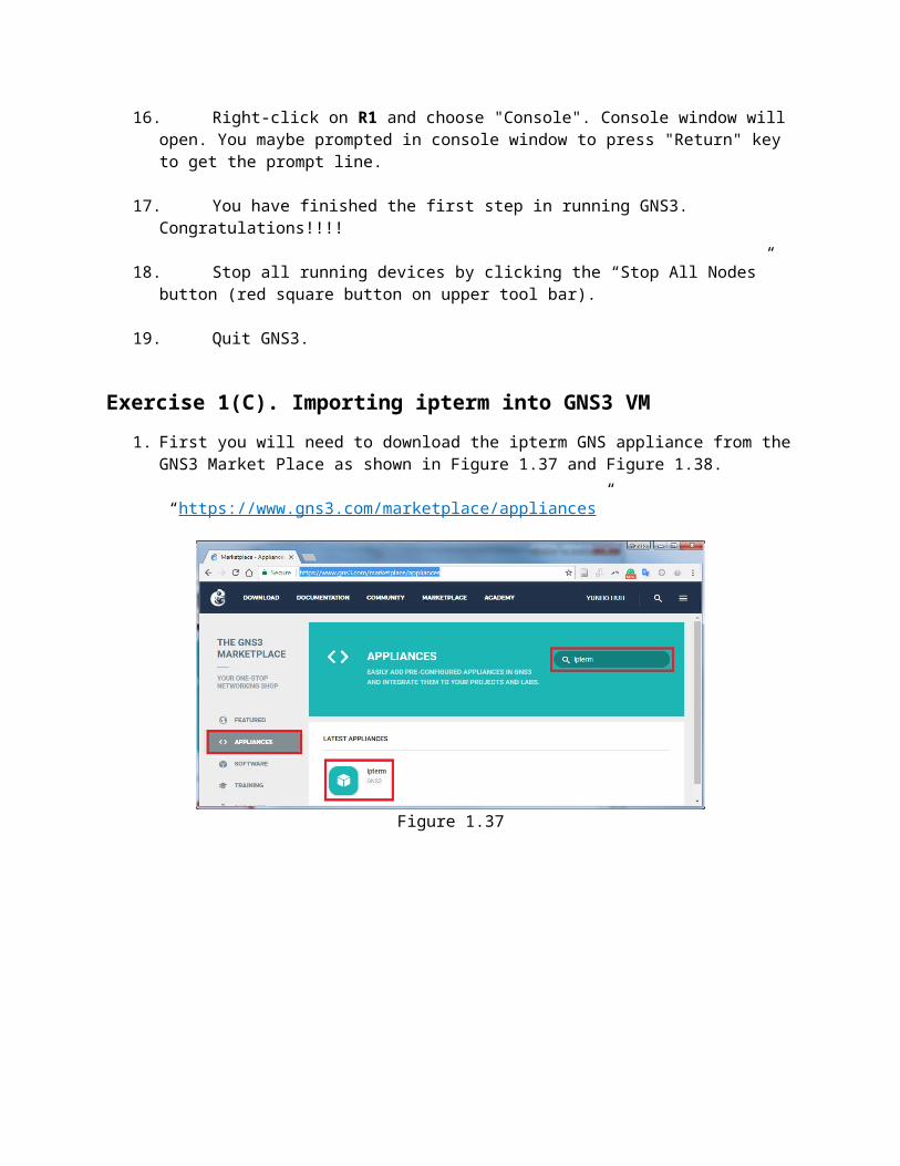
Exercise 1(C). Importing ipterm into GNS3 VM1. First you will need to download the ipterm GNS appliance from the GNS3 Market Place
as shown in Figure 1.37 and Figure 1.38.
“https://www.gns3.com/marketplace/appliances”
Figure 1.37
5 Check with Task Manager for Windows, or Activity Monitor for MacOS the cpu % value being used by process “dynamips”.

Figure 1.38
2. Open File menu and select Import appliance as shown in Figure 1.39.
Figure 1.39
3. Select the downloaded impterm.gns3a file and click Open.
4. The following screens will appear. Click Next all the way through Figure 1.42 and click Finish as shown in Figure 1.43. Then you will see the message box shown in Figure 1.44. Click OK.

Figure 1.40
Figure 1.41

Figure 1.42
Figure 1.43
Figure 1.44
5. When completed and select “Browse all devices” icon on the left side menu, then you will see the ipterm in the All device list.
Figure 1.45
6. Rename ipterm to PC as follows and remove “-“ from Default name format.
Figure 1.46

Figure 1.47
Figure 1.48

7. You will see the following screens. Click OK.
Figure 1.49.
Figure 1.50

8. Create a new project.
Figure 1.51
9. Give your project a name for example “pcsetup” shown in Figure 1.52 and Click OK.
Figure 1.52
10. Expand Browse End Devices and drag and drop PC icon to project window as shown in Figure 1.53. Note: GNS3 automatically numbers all devices.

Figure 1.53
11. Start PC-1 as shown below in Figure 1.54. Console screen will scroll with the ipterm setup progress as shown in Figure 1.55.
Figure 1.54

Figure 1.55
12. PC setup is now complete. Stop all devices by clicking on large red button. Quit GNS3

PART2. Testing the software set upIn this part we will set up a very simple network configuration to test the installed software components and to make sure all your PCs and GNS3 are working well together.
Exercise 2(A). Initiation of devices
1. Open GNS3.
2. Start a new project as explained in Exercise 1(C), step 8. Drag two instances of PC to create PC1 and PC2 in the project pane to start a network simulation as shown in Figure 2.1.
Figure 2.1 PC1 and PC2 in a GNS3 project
3. In GNS3, click on the "Add a link" tab (the 6th icon down on the left-hand side). Note that the 6th icon will change to an icon with an “X” mark (as shown in Figure 2.2 below). Click on PC1 and select eth0 as shown in Figure 2.2. Then repeat the process for PC2. You can press "esc" on your keyboard, or click the 6thicon, to exit the add a link feature.

Figure 2.2 How to link two PCs
4. Please note that the color of the dots indicates the status of the devices in GNS3. The red dots indicate that the PCs are not currently active. Now you are ready to test the simulation. Click the "Start/Resume all devices" button (large green arrow) as shown in Figure 2.3.
Figure 2.3 Two connected PCs with an active link

5. Click “Console connect all nodes” button to open console windows for each running device in the project panel as shown in Figure 2.4.
Figure 2.4

Exercise 2(B). Assigning and manipulating IP addresses
Figure 2.5
To assign an IP address A.B.C.D/xx to interface interface on a Linux device use the ifconfig command as shown below in the terminal window.
1. Assign an IP address on each of PC1 and PC2 with the following command:
a) For PC1: PC1% ifconfig eth0 10.0.1.1/24
b) For PC2: PC2% ifconfig eth0 10.0.1.2/24
Figure 2.6
ifconfig interface A.B.C.D/xxWhere interface indicates the output port, e.g., eth0, A.B.C.D indicates the IP address, e.g., 10.0.1.4, and /xx indicates the length of the subnet mask, e.g. /24 (255.255.255.0).

2. To check if you have configured the IP address correctly on each PC, type in the terminal window for each PC:
PC1% ifconfigPC2% ifconfig
3. You should see the following output on their terminal windows
Figure 2.7 ifconfig output
Exercise 2(C). Using the command PingOne of the most basic, but also most effective tools to debug IP networks is the ping command. The ping command tests whether another host or router on the Internet is reachable. The ping command sends an ICMP Echo Request datagram to an interface and expects an ICMP Echo Replay datagram in return. A few ping usage scenarios are listed below.
ISSUING PING COMMANDSWhen using ping on the Linux PCs, we recommend to always send at least
two ICMP Echo Request packets. We have observed that the first ICMP Echo Request may often be dropped due to the ARP protocol.
COMMON USES OF THE PING COMMANDping IPaddress
Issues a ping command for the host with the given IP address. The system will issue one ICMP Echo Request packet with a size of 56 bytes every second. The command is stopped by pressing Ctrl-C.
ping IPaddress –c <num>The command stops after sending a number, num, of ICMP Echo Requests.
ping IPaddress –s <num>The number of data bytes in the ICMP Echo Request is set to num

1. From PC1, send five ping messages (using the -c option) to PC2. On PC1, this is done by typing
PC1% ping 10.0.1.2 –c 5
2. From PC2, send five ping messages to PC1.
PC2% ping 10.0.1.1 –c 5
3. If you did everything correctly, you should see the ping response messages as shown in Figure 2.8.
Figure 2.8 Terminal output for ping commands
4. Stop the PCs (red button) and quit GNS3.